Westell A9081XXYY-07 Spread Spectrum Transmitter User Manual 5645 rev 1
Westell Inc Spread Spectrum Transmitter 5645 rev 1
Westell >
Users Manual

030-300479 Rev. A
Draft 1 – 10/17/05
Copyright © 2005 Westell, Inc. 030-300479 Rev. A
ULTRALINE IIB (MODEL 816030)
USER GUIDE

030-300479 Rev. A
Draft 1 – 10/17/05
030-300479 Rev. A 2 October 2005
User Guide UltraLine II (Model A90-816030)
TABLE OF CONTENTS
1. PRODUCT DESCRIPTION..................................................................................................................................4
2. SAFETY INSTRUCTIONS ..................................................................................................................................4
3. REGULATORY INFORMATION .......................................................................................................................5
3.1 FCC Compliance Note................................................................................................................................5
3.2 Canada Certification Notice .......................................................................................................................6
4. NETWORKING REQUIREMENTS ....................................................................................................................7
5. HARDWARE FEATURES...................................................................................................................................8
5.1 LED Indicators ...........................................................................................................................................8
5.2 Rear Panel Components..............................................................................................................................9
5.3 Connector Descriptions ..............................................................................................................................9
5.4 Pin-out Descriptions .................................................................................................................................10
6. INSTALLING THE HARDWARE.....................................................................................................................11
6.1 Installation Requirements.........................................................................................................................11
6.2 Before you begin ......................................................................................................................................11
6.3 Microfilters...............................................................................................................................................11
6.4 Hardware Installations..............................................................................................................................12
6.4.1 Installation via DSL1/DSL2 ....................................................................................................................12
6.4.2 Connecting PCs via Wireless...................................................................................................................13
7. CONFIGURING THE GATEWAY FOR INTERNET CONNECTION............................................................14
7.1 Confirming a DSL Sync ...........................................................................................................................14
7.2 Setting Up a Connection Profile...............................................................................................................15
7.3 Establishing a PPP Session.......................................................................................................................18
7.4 Disconnecting a PPP Session ...................................................................................................................20
8. SETTING UP Macintosh OS X...........................................................................................................................21
9. BASIC MODE.....................................................................................................................................................25
10. HOME .............................................................................................................................................................26
10.1 Connection................................................................................................................................................26
10.2 Connection Summary ...............................................................................................................................27
11. STATUS..........................................................................................................................................................28
11.1 About........................................................................................................................................................28
11.2 LAN Devices............................................................................................................................................29
11.3 RIP Routing Tables ..................................................................................................................................30
11.4 Wireless Stations ......................................................................................................................................31
12. DIAGNOSTICS...............................................................................................................................................32
13. RESTART .......................................................................................................................................................35
14. ADVANCED MODE......................................................................................................................................37
15. CONFIGURATION ........................................................................................................................................38
15.1 Firewall Configuration .............................................................................................................................38
15.2 Port Forwarding Configuration.................................................................................................................40
15.3 Port Triggering .........................................................................................................................................44
15.4 ALG Configuration ..................................................................................................................................46
15.5 LAN Configuration ..................................................................................................................................47
15.5.1 DHCP.......................................................................................................................................................47
15.5.2 DNS .........................................................................................................................................................48

030-300479 Rev. A
Draft 1 – 10/17/05
030-300479 Rev. A 3 October 2005
User Guide UltraLine II (Model A90-816030)
15.5.3 Public LAN – Multiple IP Address Passthrough .....................................................................................49
15.5.4 IP Passthrough – Single IP Address Passthrough ....................................................................................50
15.5.5 Static NAT...............................................................................................................................................55
15.5.6 Port Mapping ...........................................................................................................................................57
15.6 Spanning Tree...........................................................................................................................................58
15.7 WAN Configuration .................................................................................................................................59
15.7.1 VersaPort .................................................................................................................................................59
15.7.2 Private LAN – Configuring NAT ............................................................................................................60
15.7.3 Ethernet WAN Uplink .............................................................................................................................61
15.7.4 Public LAN – Multiple IP Address Passthrough .....................................................................................63
15.7.5 VCs ..........................................................................................................................................................64
15.7.6 VPN .........................................................................................................................................................68
15.7.7 Routing Table ..........................................................................................................................................70
15.8 Wireless Configuration.............................................................................................................................72
15.8.1 Basic ........................................................................................................................................................72
15.8.2 Wireless Security .....................................................................................................................................73
15.8.3 MAC Filter...............................................................................................................................................76
15.8.4 Advanced Wireless Settings ....................................................................................................................79
16. MAINTENANCE............................................................................................................................................80
16.1 Login Administration ...............................................................................................................................80
16.2 Event Log .................................................................................................................................................81
16.3 Firewall Log .............................................................................................................................................83
16.4 Update Device ..........................................................................................................................................84
16.5 Remote Access .........................................................................................................................................85
16.6 Statistics....................................................................................................................................................86
16.6.1 Ethernet Port Statistics.............................................................................................................................86
16.6.2 Switch Ports Statistics..............................................................................................................................87
16.6.3 Transceiver Statistics ...............................................................................................................................88
16.6.4 ATM Statistics.........................................................................................................................................89
16.6.5 Wireless Statistics....................................................................................................................................90
17. NAT SERVICES .............................................................................................................................................91
18. PRODUCT SPECIFICATIONS......................................................................................................................95
19. TECHNICAL SUPPORT INFORMATION ...................................................................................................97
20. WARRANTY AND REPAIRS .......................................................................................................................97
21. PUBLICATION INFORMATION..................................................................................................................98

030-300479 Rev. A
Draft 1 – 10/17/05
030-300479 Rev. A 4 October 2005
User Guide UltraLine II (Model A90-816030)
1. PRODUCT DESCRIPTION
Your Westell® UltraLine IIB functions as a Gateway or Router and enables you to connect multiple PCs on your
LAN to the Internet. The UltraLine’s 802.11 wireless interface enables you to establish a secure wireless connection
with mobile computing devices.
Hereafter, the Westell® UltraLine IIB will be referred to as “Gateway” or “modem.”
2. SAFETY INSTRUCTIONS
The following important safety instructions should be followed when using your telephone equipment.
WARNING: Please save these instructions.
Do not use this product near water, for example, near a bathtub, washbowl, kitchen sink or laundry tub, in a
wet basement or near a swimming pool.
Avoid using a telephone (other than a cordless type) during an electrical storm. There may be a remote risk
of electric shock from lightning.
Do not use the telephone to report a gas leak in the vicinity of the leak.
Do not connect this equipment in an environment that is unsuitable. The voice over IP (VoIP) ports of the
equipment are suitable for connection to intra-building or nonexposed wiring only.
Never install any telephone wiring during a lightning storm.
Never install telephone jacks in wet locations unless the jack is specifically designed for wet locations.
Never touch non-insulated telephone wires or terminals unless the telephone line has been disconnected at
the network interface.
Use caution when installing or modifying telephone lines.
WARNING
Risk of electric shock. Voltages up to 140 Vdc (with reference to ground) may
be present on telecommunications circuits.

030-300479 Rev. A
Draft 1 – 10/17/05
030-300479 Rev. A 5 October 2005
User Guide UltraLine II (Model A90-816030)
3. REGULATORY INFORMATION
3.1 FCC Compliance Note
(FCC ID: CH8A9081XXYY-07)
This equipment has been tested and found to comply with the limits for a Class B digital device, pursuant to Part 15
of the Federal Communication Commission (FCC) Rules. These limits are designed to provide reasonable protection
against harmful interference in a residential installation. This equipment generates, uses, and can radiate radio
frequency energy, and if not installed and used in accordance with the instructions, may cause harmful interference
to radio communications. However, there is no guarantee that interference will not occur in a particular installation.
If this equipment does cause harmful interference to radio or television reception, which can be determined by
turning the equipment OFF and ON, the user is encouraged to try to correct the interference by one or more of the
following measures:
• Reorient or relocate the receiving antenna.
• Increase the separation between the equipment and the receiver.
• Connect the equipment to a different circuit from that to which the receiver is connected.
• Consult the dealer or an experienced radio/TV technician for help.
This device complies with Part 15 of the FCC Rules. Operation is subject to the following two conditions: (1) This
device may not cause harmful interference, and (2) this device must accept any interference received, including
interference that may cause undesired operation.
Modifications made to the product, unless expressly approved by Westell Inc., could void the users’ right to
operate the equipment.
RF EXPOSURE
The antennas used for this transmitter must be installed to provide a separation distance of at least 20 cm
from all persons and must not be co-located or operating in conjunction with any other antenna or
transmitter. End users and installers must be provided with antenna installation instructions and transmitter
operating conditions for satisfying RF exposure compliance.
PART 68 – COMPLIANCE REGISTRATION
This equipment is designated to connect to the telephone network or premises wiring using a compatible modular
jack that is Part 68 compliant. An FCC compliant telephone cord and modular plug is provided with the equipment.
Refer to the installations instructions in this User Guide for details.
A plug and jack used to connect this equipment to the premises wiring and telephone network must comply with the
applicable FCC Part 68 rules and requirements adopted by the ACTA. A compliant telephone cord and modular plug
is provided with this product. It is designed to be connected to a compatible modular jack that is also compliant.
Refer to the installation instructions in this User Guide for details.
If this terminal equipment (Model 816030) causes harm to the telephone network, the telephone company may
request you to disconnect the equipment until the problem is resolved. The telephone company will notify you in
advance if temporary discontinuance of service is required. If advance notification is not practical, the telephone
company will notify you as soon as possible. You will be advised of your right to file a complaint with the FCC if
you believe such action is necessary. If you experience trouble with this equipment (Model 816030), do not try to
repair the equipment yourself. The equipment cannot be repaired in the field. Contact your ISP, or contact the
original provider of your DSL equipment.

030-300479 Rev. A
Draft 1 – 10/17/05
030-300479 Rev. A 6 October 2005
User Guide UltraLine II (Model A90-816030)
The telephone company may make changes to their facilities, equipment, operations, or procedures that could affect
the operation of this equipment. If this happens, the telephone company will provide advance notice in order for you
to make the modifications necessary to maintain uninterrupted service.
If your home has specially wired alarm equipment connected to the telephone line, ensure that the installation of this
equipment (Model 816030) does not disable your alarm equipment. If you have questions about what will disable
alarm equipment, consult your telephone company or a qualified installer. This equipment cannot be used on public
coin phone service provided by the telephone company. Connection of this equipment to party line service is subject
to state tariffs.
3.2 Canada Certification Notice
The Industry Canada label identifies certified equipment. This certification means that the equipment meets certain
telecommunications network protective, operations and safety requirements as prescribed in the appropriate
Terminal Equipment Technical Requirements document(s). The department does not guarantee the equipment will
operate to the user’s satisfaction.
This equipment meets the applicable Industry Canada Terminal Equipment Technical Specification. This is
confirmed by the registration number. The abbreviation, IC, before the registration number signifies that registration
was performed based on a Declaration of Conformity indicating that Industry Canada technical specification were
met. It does not imply that Industry Canada approved the equipment. The Ringer Equivalence Number (REN) is 0.0.
The Ringer Equivalence Number that is assigned to each piece of terminal equipment provides an indication of the
maximum number of terminals allowed to be connected to a telephone interface. The termination on an interface
may consist of any combination of devices subject only to the requirement that the sum of the Ringer Equivalence
Numbers of all the devices does not exceed five.
Before installing this equipment, users should ensure that it is permissible to be connected to the facilities of the
local Telecommunication Company. The equipment must also be installed using an acceptable method of
connection. The customer should be aware that compliance with the above conditions may not prevent degradation
of service in some situations. Connection to a party line service is subject to state tariffs. Contact the state public
utility commission, public service commission, or corporation commission for information.
If your home has specially wired alarm equipment connected to the telephone line, ensure that the installation of this
equipment (Model 816030) does not disable your alarm equipment. If you have questions about what will disable
alarm equipment, consult your telephone company or a qualified installer.
If you experience trouble with this equipment (Model 816030) do not try to repair the equipment yourself. The
equipment cannot be repaired in the field and must be returned to the manufacturer. Repairs to certified equipment
should be coordinated by a representative, and designated by the supplier. Refer to section 20 in this User Guide for
further details. The termination on an interface may consist of any combination of devices subject only to the
requirement that the sum of the Ringer Equivalence Numbers of all the devices does not exceed five.
Operation of this equipment (Model 816030) is subject to the following conditions: (1) This device may not cause
harmful interference, and (2) This equipment must accept any interference received, including interference that may
cause undesired operation.
To reduce potential radio interference to users when a detachable antenna is used with this equipment the antenna
type and its gain should be so chosen that the equivalent isotropically radiated power (EIRP) is not more than that
required for successful communication.” Users should ensure, for their own protection, that the electrical ground
connections of the power utility, telephone lines, and internal, metallic water pipe system, if present, are connected
together. This precaution may be particularly important in rural areas.
CAUTION
Users should not attempt to make such connections themselves, but should contact the appropriate
electrical inspection authority, or electrician, as appropriate.

030-300479 Rev. A
Draft 1 – 10/17/05
030-300479 Rev. A 7 October 2005
User Guide UltraLine II (Model A90-816030)
4. NETWORKING REQUIREMENTS
The following system specifications are required for optimum performance of the Gateway via 10/100 Base-T
Ethernet, Wireless installations.
CONNECTION TYPE MINIMUM SYSTEM REQUIREMENTS
ETHERNET
(E1, E2, E3, E4)
• Pentium® or equivalent class machines
• Microsoft® Windows® (98 SE, ME, 2000, NT 4.0, or XP)
Macintosh® OS X, or Linux installed
• Microsoft® Server 2003 (all versions)
• Internet Explorer 4.x or Netscape Navigator 4.x or higher
• 64 MB RAM (128 MB recommended)
• 10 MB of free hard drive space
• TCP/IP Protocol stack installed
• 10/100 Base-T Network Interface Card (NIC)
• Computer Operating System CD-ROM on hand
WIRELESS
IEEE 802.11b/g
• Pentium® or equivalent class machines
• Microsoft® Windows® (98 SE, ME, 2000, or XP) or
Macintosh® OS X installed
• Microsoft® Server 2003 (all versions)
• Computer Operating System CD-ROM on hand
• Internet Explorer 4.x or Netscape Navigator 4.x or higher
• 64 MB RAM (128 MB recommended)
• 10 MB of free hard drive space
• An available IEEE 802.11b/g PC adapter

030-300479 Rev. A
Draft 1 – 10/17/05
030-300479 Rev. A 8 October 2005
User Guide UltraLine IIB (Model A90-816030)
5. HARDWARE FEATURES
5.1 LED Indicators
This section explains the LED States and Descriptions of your Gateway. LED indicators are used to verify the unit’s
operation and status.
LED States and Descriptions
LED State Description
Solid Green Gateway power is ON.
Solid Red
POST (Power On Self Test), Failure (not bootable) or Device
Malfunction. Note: The Power LED should be red no longer
than two seconds after the power on self test passes.
POWER
(PWR)
OFF Gateway power is OFF.
Solid Green
Powered device is connected to the associated port (includes
devices with wake-on LAN capability where slight voltage is
supplied to an Ethernet connection).
Flashing Green 10/100 Base-T Ethernet LAN activity is present (LAN traffic in
either direction).
E1, E2, E3, E4
(Ethernet LAN)
OFF Gateway power is OFF, no cable or no powered device is
connected to the associated port.
Solid Green Wireless is enabled and functioning.
Flashing Green Wireless LAN activity present (traffic in either direction).
WI FI Off Wireless is disabled or not functioning.
Solid Green Good DSL sync.
Flashing Green DSL attempting to sync.
Solid Red DSL failed to sync at the physical layer. Gateway is in safeboot
mode.
DSL1
DSL2
Off No DSL signal detected. Gateway power is OFF.
Solid Green Bonded operation is functioning properly.
BONDED Off No Bonding between the two DSL lines.
Solid Green Internet link established.
Flashing Green
IP connection established and IP Traffic is passing through
device (in either direction).
Note: If the IP or PPP session is dropped due to an idle timeout,
the light will remain solid green, if an ADSL connection is still
present.
If the session is dropped for any other reason, the light is turned
OFF. The light will turn red when it attempts to reconnect and
DHCP or PPP fails).
Solid Red
Device attempted to become IP connected and failed (no DHCP
response, no PPP response, PPP authentication failed, no IP
address from IPCP, etc.).
INTERNET
OFF Modem power is OFF, Modem is in Bridge Mode, or the
connection is not present.
NOTE: Safe Boot is reflected when the Power and Internet LED’s are both Red and all other LED’s are off.
030-300479 Rev. A
Draft 1 – 10/17/05
030-300479 Rev. A 9 October 2005
User Guide UltraLine IIB (Model A90-816030)
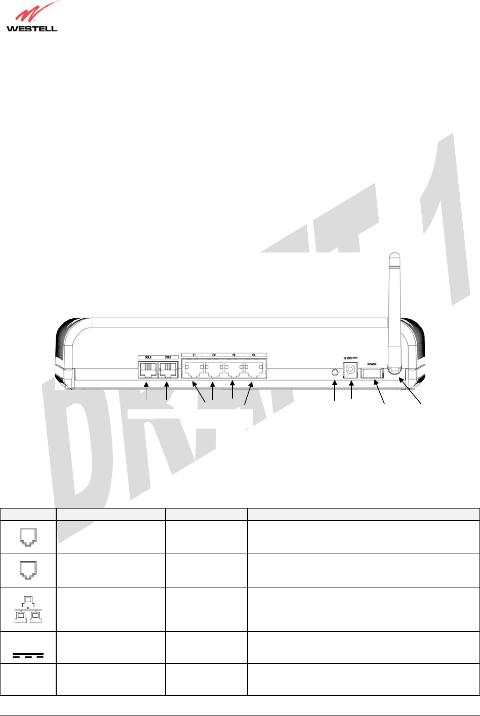
5.2 Rear Panel Components
• DSL2 connector (RJ-11)
• DSL1 connector (RJ-11)
• (4) Ethernet connector (RJ-45)
• Reset button
• Power connector (barrel)
• Power switch
• Wireless IEEE 802.11b/g SMA connector and antenna
Figure 1. Rear View of UltraLine IIB
5.3 Connector Descriptions
The following chart displays the connector types for the UltraLine IIB.
SYMBOL NAME TYPE FUNCTION
DSL2 LINE RJ-11 Connects to an ADSL-equipped telephone jack or
DSL connection of a POTS splitter.
DSL1 LINE RJ-11 Connects to an ADSL-equipped telephone jack or
DSL connection of a POTS splitter.
ETHERNET
(1, 2, 3, 4) RJ-45 10/100 Base-T Ethernet Connection to PC or Hub.
12 VDC
POWER Barrel connector Connection to DC (12V) Power Connector.
Wireless ANTENNA SMA connector
and antenna Connects to wireless IEEE 802.11b/g device.
DSL 2 ETHERNET
(
E1
,
E2
,
E3
,
E4
)
12 VDC POWER
SWITCH
RESET
DSL 1 WIRELESS
CONNECTOR/
ANTENNA

030-300479 Rev. A
Draft 1 – 10/17/05
030-300479 Rev. A 10 October 2005
User Guide UltraLine IIB (Model A90-816030)
5.4 Pin-out Descriptions
The following table lists the Gateway’s port pin-outs and descriptions.
Port Pin-out Description
1,2,5,6 Not Used
3 DSL TIP
DSL2
DSL1 4 DSL Ring
1 Rx+
2 Rx-
3 Tx+
4,5,7,8 Not Used
ETHERNET
E1, E2, E3, E4
6 Tx-

030-300479 Rev. A
Draft 1 – 10/17/05
030-300479 Rev. A 11 October 2005
User Guide UltraLine IIB (Model A90-816030)
6. INSTALLING THE HARDWARE
6.1 Installation Requirements
To install your Gateway, you will need one of the following:
• A Network Interface Card (NIC) installed in your PC
• An IEEE 802.11b/g adapter
IMPORTANT: Please wait until you have received notification from your Internet service provider (ISP) that your
DSL line has been activated before installing the Gateway and the software. Internet service provider subscriber
software and connection requirements may vary. Consult your ISP for installation instructions.
6.2 Before you begin
Make sure your kit contains the following items:
• Westell® UltraLine IIB
• Power Supply
• RJ-45 Ethernet cable (straight-through) (yellow)
• SMA Antenna
• Westell CD-ROM containing User Guide in PDF format
• Quick Start Guide
6.3 Microfilters
ADSL signals must be blocked from reaching each telephone, answering machine, fax machine, computer modem or
any similar conventional device. Failure to do so may degrade telephone voice quality and ADSL performance.
Install a microfilter if you desire to use the DSL-equipped line jack for telephone, answering machine, fax machine
or other telephone device connections. Microfilter installation requires no tools or telephone rewiring. Just unplug the
telephone device from the baseboard or wall mount and snap in a microfilter. Next, snap in the telephone device.
You can purchase microfilters from your local electronics retailer or contact the original provider of your DSL
equipment.

030-300479 Rev. A
Draft 1 – 10/17/05
030-300479 Rev. A 12 October 2005
User Guide UltraLine IIB (Model A90-816030)
6.4 Hardware Installations
NOTE: If you are using your Gateway in conjunction with an Ethernet Hub or Switch, refer to the manufacturer’s
instructions for proper installation and configuration. When using a Microfilter, be certain that the DSL phone cable
is connected to the “DSL/HPN” non-filtered jack. Please wait until you have received notification from your ISP that
your DSL line has been activated before installing the Gateway. Westell recommends the use of a surge
suppressor to protect equipment attached to the power supply. An additional Ethernet cable may be required
depending on the installation method you are using. Ethernet cables can be purchased at your local computer
hardware retailer.
6.4.1 Installation via DSL1/DSL2
IMPORTANT: Before you connect via 10/100 Base-T, you must have an available Ethernet card installed in
your computer. If your Ethernet card does not auto-negotiate, you must set it to half duplex. Refer to the
Ethernet card manufacturer’s instructions for installing and configuring your Ethernet card.
1. Connect the DSL phone cable from the connector marked DSL on the rear panel of the Gateway to the DSL-
equipped telephone line jack on the wall. IMPORTANT: Do not use a DSL filter on this connection. You must
use the phone cord that was provided with the kit.
2. Connect the yellow Ethernet cable (provided with your kit) from any one of the Ethernet jacks marked
ETHERNET on the rear panel of the Gateway to the Ethernet port on your computer. Repeat this step to
connect up to three additional PCs to your Westell Gateway.
NOTE: When using the yellow VERSAPORT™2 jack in Private LAN mode, you may connect either the yellow
Ethernet cable (provided with your kit) or any other Ethernet cable to the VERSAPORT™2 jack as the
VERSAPORT™2 jack will function as a fifth Ethernet switch. You may also connect to any of the four black
Ethernet jacks on the rear panel of the Gateway as they serve as an Ethernet switch.
3. Connect the power supply cord to the power connector marked 12 VDC on the rear panel of the Gateway. Plug the
other end of the power supply into a wall socket, and then turn on the power switch (if it is not already turned on).
4. Check to see if the DSL LED is solid green. If the DSL LED is solid green, the Gateway is functioning properly.
5. Check to see if the Ethernet LED is solid green. Solid green indicates that the Ethernet connection is functioning
properly.
6. Check to see if the Internet LED is solid green. Solid green indicates that an Internet link has been established.
Congratulations! You have completed the DSL installation for your Gateway. No software installation is required when
using only an Ethernet connection. You must now proceed to section 7, “Configuring the Gateway for Internet
Connection.”
!

030-300479 Rev. A
Draft 1 – 10/17/05
030-300479 Rev. A 13 October 2005
User Guide UltraLine IIB (Model A90-816030)
6.4.2 Connecting PCs via Wireless
IMPORTANT: If you are connecting to the Gateway via a wireless network adapter, the SSID must be the same for
both the Gateway and your PC’s wireless network adapter. The default SSID for the Gateway is the serial number of
the unit (located below the bar code on the bottom of the unit and also on the Westell shipping carton). Locate and
run the utility software provided with your PC’s Wireless network adapter and enter the SSID value. The PC’s
wireless network adapter must be configured with the SSID (in order to communicate with the Gateway) before you
begin the account setup and configuration procedures. Later, for privacy you can change the SSID by following the
procedures outlined in section 15.8 (Wireless Configuration).
IMPORTANT: Client PCs can use any Wireless Fidelity (Wi-Fi) 802.11b/g/g+ certified card to communicate with
the Gateway. The Wireless card and Gateway must use the same security code type. If you use WPA-PSK or WEP
wireless security, you must configure your computer’s wireless adapter for the security code that you use. You
can access the settings in the advanced properties of your wireless network adapter.
To network the Gateway to additional computers in your home or office using a wireless installation, you will need
to confirm the following:
1. Ensure that an 802.11b/g wireless network adapter has been installed in each PC on your wireless network.
2. Install the appropriate drivers for your Wireless IEEE802.11b or IEEE802.11g adapter.
3. Make sure the SMA antenna connector is loose. Orient the antenna in the proper configuration. Then, tighten the
antenna knob to lock it into place.
4. Connect the DSL phone cable from the connector marked DSL on the rear panel of the Gateway to the DSL-
equipped telephone line jack on the wall. IMPORTANT: Do not use a DSL filter on this connection. You must
use the phone cord that was provided with the Gateway kit.
5. Connect the power supply cord to the power connector marked 12 VDC on the rear panel of the Gateway. Plug
the other end of the power supply into a wall socket, and then turn on the power switch (if it is not already turned
on).
6. Check to see if the DSL LED is solid green. If the DSL LED is solid green, the Gateway is functioning properly.
7. Check to see if the Gateway’s Wireless LED is solid green. This means that the Wireless interface is functioning
properly.
8. Check to see if the Internet LED is solid green. Solid green indicates that an Internet link as been established.
Congratulations! You have completed the Wireless installation for your Gateway. You must now proceed section 7,
“Configuring the Gateway for Internet Connection.”
030-300479 Rev. A
Draft 1 – 10/17/05
030-300479 Rev. A 14 October 2005
User Guide UltraLine IIB (Model A90-816030)
7. CONFIGURING THE GATEWAY FOR INTERNET CONNECTION
To browse the Internet using your UltraLine IIB, you must confirm your DSL sync, set up your account profile, and
establish a PPP session with your Internet service provider (ISP).
NOTE: Internet service provider subscriber software and connection requirements may vary. Refer to the Internet
service provider’s installation manual to install the software required for your Internet connection.
7.1 Confirming a DSL Sync
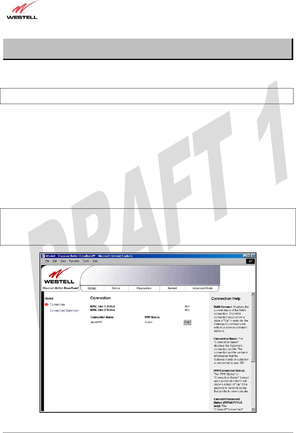
After connecting the hardware for the UltraLine IIB, start your Internet browser and type http://192.168.1.1/ in the
browser’s address bar. Next, press ‘Enter’ on your keyboard. The following Connection Overview screen will be
displayed.
You must have active DSL service before the UltraLine IIB can synchronize with your ISP’s equipment. To determine if
the Gateway has a DSL sync, view the DSL Connection Rate at the Connection Overview field. If the status reads No
DSL Connection, check the DSL physical connection, explained in section 6 (INSTALLING THE HARDWARE) of
this User Guide. The following screen shows the DSL connection rate with values that indicate a successful DSL SYNC
has been established. The connection rate values represent the transmission speed of your DSL line. (The Gateway may
take time to report these values.)
NOTE: If no DSL sync is established, the Connection button will not be displayed in the Connection Overview
screen. To determine if the DSL sync is established, check the Gateway’s DSL LED. If the DSL LED is not solid
green, you do not have a DSL sync established. Contact your Internet service provider for further instructions. The
Gateway will handle transmission rates up to 8 Mbps. Your actual DSL rates may vary depending on your Internet
service provider.
030-300479 Rev. A
Draft 1 – 10/17/05
030-300479 Rev. A 15 October 2005
User Guide UltraLine IIB (Model A90-816030)
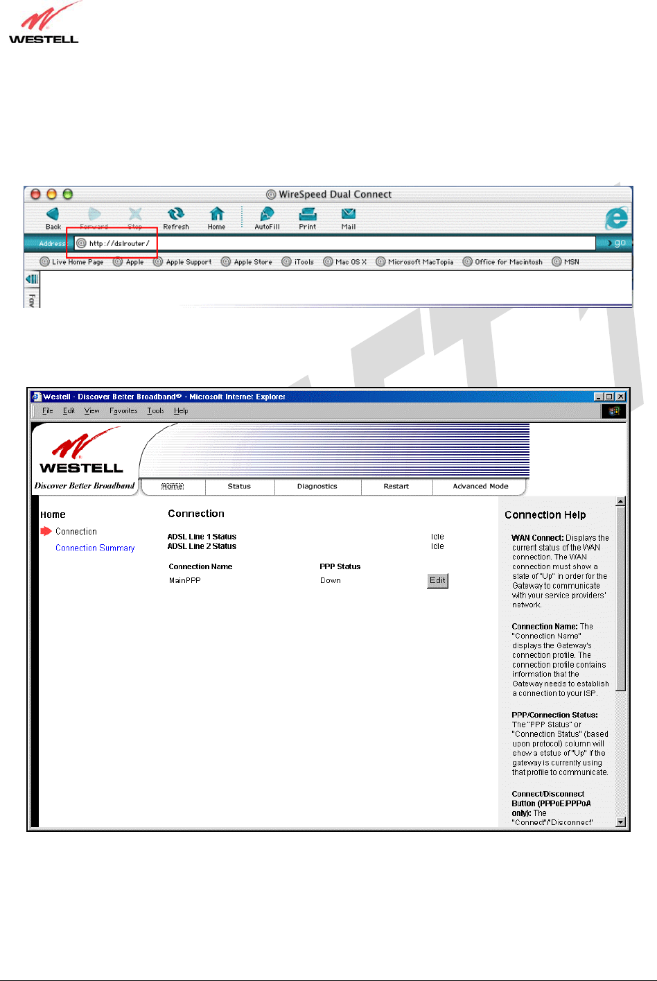
Connection Overview Displays your ADSL connection rate.
Connection Name The name of the connection profile you are using.
PPP Status UP = PPP session established
DOWN = No PPP session established.
Connect/Disconnect Click Connect to establish a PPP session.
Click Disconnect to disconnect a PPP session
Edit Click Edit to edit the connection profile.
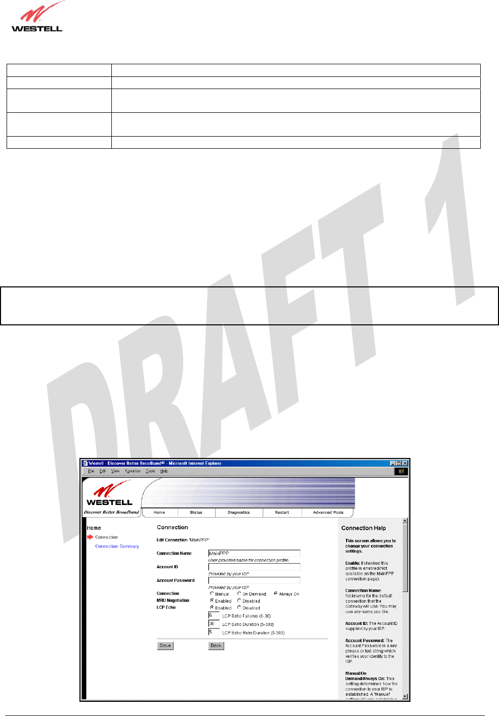
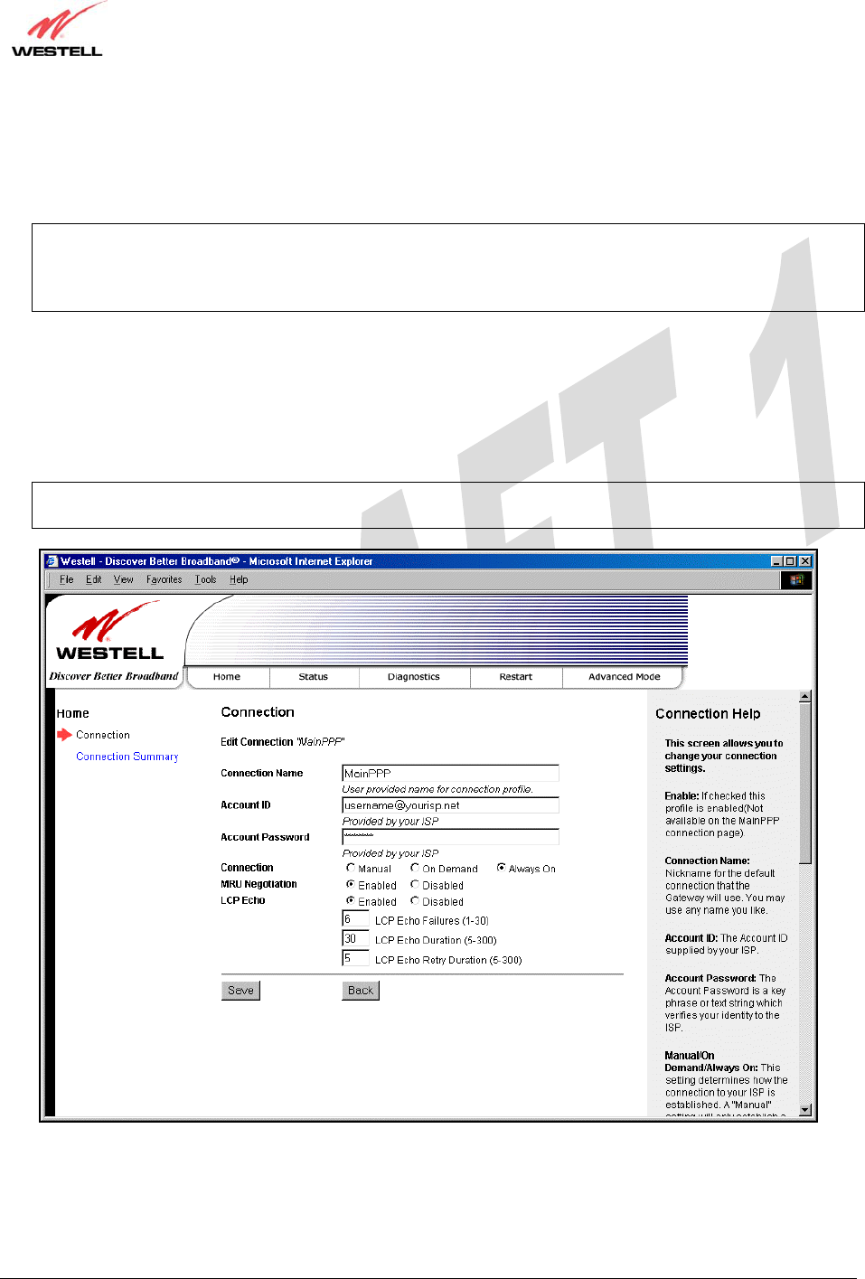
7.2 Setting Up a Connection Profile
After you have confirmed your DSL sync, click Edit in the Connection Overview screen to set up your connection
profile. The following Edit Connection screen enables you to add new connection profiles or to edit existing
connection profiles. Connection profiles can be associated with specific service settings, such as connection settings
or NAT services, enabling you to customize your Gateway for specific users. The Connection Name field allows
you to enter the desired name that you wish to use for each profile that you set up. You may create and store up to
eight unique connection profiles in your Gateway, which you can use once you establish a PPP session with your
Internet service provider (ISP).
Important: Before you set up a connection profile, you must obtain your Account ID, Account Password, and
VPI/VCI values from your Internet service provider. You will use information when you set up your account
parameters. If you are at a screen and need help, refer to the Help section located at the right of the screen.
Profile Parameters include:
● Connection Name-the Connection Name is a word or phrase that you use to identify your account.
(You may enter up 64 characters in this field.)
● Account ID-the Account ID is provided by your Internet Service Provider.
(You may enter up 255 characters in this field.)
● Account Password-the Account Password is provided by your Internet Service Provider.
(You may enter up 255 characters in this field.)
030-300479 Rev. A
Draft 1 – 10/17/05
030-300479 Rev. A 16 October 2005
User Guide UltraLine IIB (Model A90-816030)
At the Edit Connection screen, complete the following steps to set up your connection profile:
1) Type your Connection Name, Account ID and Account Password in the fields provided. The Account
Password field will be masked with asterisks for security purposes.
IMPORTANT: Initially, you must use the factory default connection name “MainPPP” to establish a PPP
session with your ISP. Then, if you want set up additional profiles, you may use connection names of your
choice.The Connection Name is the name associated each connection profile. The Account ID and Account
Password are provided by your Internet service provider and will be used for connection profile that you set up.
2) At the field labeled Connection, select the connection type (Manual, On Demand, Always On) that you want to
use with this connection name. The factory default connection type is “Always On.”
3) Select the MRU Negotiation and LCP settings that you want to use with this connection name. For details on
these settings, refer to the following table.
4) Click Save to save any changes that you have made to this screen.
5) Click Back to return to the main Connection screen.
NOTE: If you click Back before you click Save, the previously saved settings will remain active, and any recent
changes that you have made to this screen will not take effect. You must click Save to save the settings.

030-300479 Rev. A
Draft 1 – 10/17/05
030-300479 Rev. A 17 October 2005
User Guide UltraLine IIB (Model A90-816030)
Connection
Edit Connection Factory Default = MainPPP
The name of the default connection profile. Westell recommends that you use the
Default parameter.
Connection Name This field allows you to enter a new connection name of your choice (up to 64
characters).
Account ID The account ID (provided by your Internet service provider ).
Account Password The account password that you are using to connect to your Internet service provider
(provided by your Internet service provider ).
Connection Factory default = Always On
Manual: Selecting this feature allows you to manually establish your PPP session.
On Demand: Selecting this feature allows the Gateway to automatically re-establish
your PPP session on demand anytime your PC requests Internet activity (for example,
browsing the Internet, email, etc.). When you have traffic, it may cause a delay.
Always On: Selecting this feature allows the Gateway to automatically establish a PPP
session when you log on or if the PPP session goes down.
MRU Negotiation Factory Default = Enabled
When Enabled is selected, the Maximum Received Unit (MRU) will enforce MRU
negotiations.
If Disabled, this function will not be activated.
LCP Echo Factory Default = Enable
If Disabled is selected, this option will disable the modem LCP Echo transmissions.
LCP Echo Failures Factory Default = 6
Indicates number of continuous LCP echo non-responses received before the PPP
session is terminated. This value must be between 1 and 30 inclusive.
LCP Echo Duration Factory Default = 30
The interval between LCP Echo transmissions with responses. This value must be
between 5 and 300 seconds inclusive and greater than or equal to the Retry Duration.
LCP Echo Retry Duration Factory Default = 5
The interval between LCP. Echo after no response.
This value must be between 5 and 300 seconds inclusive.
030-300479 Rev. A
Draft 1 – 10/17/05
030-300479 Rev. A 18 October 2005
User Guide UltraLine IIB (Model A90-816030)
7.3 Establishing a PPP Session
After you have set up your connection profile and clicked Save, view the PPP Status field at the Connection
Overview screen. If the PPP Status displays Down, click the Connect button to establish a PPP session.
NOTE: Whenever the PPP Status displays Down, you do not have a PPP session established. If your Gateway’s
connection setting is set to “Always On” or “On Demand,” after a brief delay, the PPP session will be established
automatically and the PPP Status will display Up. If the connection setting is set to “Manual,” you must click on the
Connect button to establish a PPP session. Once the PPP session has been established (PPP Status displays Up), you
may proceed with your Gateway’s configuration. (Refer to the preceding Edit Connection screen to change your
connection setting.) The factory default connection setting is “Always On.”
When the Connection screen displays Up in the PPP Status field, this indicates that you have established a PPP
session with your ISP. As shown in the following screen, MainPPP is the factory default connection name used to
establish a PPP session with your ISP. After you have established your PPP session, you may use other connection
profiles that you have created via the Edit button. The name of the profile will be displayed in the Connection Name
field. If needed, refer to section 7.2 for details on setting up a connection profile.
NOTE: If you experience problems establishing a PPP session, contact your ISP for further instructions.
030-300479 Rev. A
Draft 1 – 10/17/05
030-300479 Rev. A 19 October 2005
User Guide UltraLine IIB (Model A90-816030)
After you have established a PPP session with your ISP, you are ready to browse the Internet. For example, to visit
Westell’s home page, type http://www.westell.com in your Internet browser’s address bar and then press ‘Enter’ on
your keyboard.
When you are ready to return to the Gateway’s interface, type http://192.168.1.1 in your browser’s address bar, and
then press ‘Enter’ on your keyboard.
030-300479 Rev. A
Draft 1 – 10/17/05
030-300479 Rev. A 20 October 2005
User Guide UltraLine IIB (Model A90-816030)
7.4 Disconnecting a PPP Session
If you have finished browsing the Internet and want to disconnect from your Internet service provider, click the
Disconnect button in the Connection Overview screen. A pop-up screen will appear. Click OK to disconnect the
PPP session.
IMPORTANT: If you disconnect the PPP session, this will disconnect the Gateway from the Internet, and all users
will be disconnected until the PPP session is re-established.
If you clicked the Disconnect button in the Connection Overview screen, the PPP Status should display Down. This
means that you no longer have a PPP session (no IP connection to your Internet service provider); however, your
DSL session will not be affected. When you are ready to end your DSL session, simply power down the Gateway via
the power switch on the Gateway’s rear panel.
When you are ready to establish a PPP session, click the Connect button. (If you powered down the Gateway, you
must first power up the Gateway and then log on to your account profile to establish a PPP session.)
NOTE: When you are ready to exit the Gateway’s interface, click the X (close) in the upper-right corner of the
screen. Closing the window will not affect your PPP Status (your PPP session will not be disconnected). You must
click the disconnect button to disconnect your PPP session. When you are ready to restore the Gateway’s interface,
you must start your Internet browser and type http://dslrouter/ or type http://192.168.1.1/ in the browser’s address
bar and then press ‘Enter’ on your keyboard.
030-300479 Rev. A
Draft 1 – 10/17/05
030-300479 Rev. A 21 October 2005
User Guide UltraLine IIB (Model A90-816030)
8. SETTING UP MACINTOSH OS X
This section provides instructions on how to use Macintosh Operating System 10 with the Gateway. Follow the
instructions in this section to create a new network configuration for Macintosh OS X.
NOTE: Macintosh computers must use the Modem Ethernet installation. Refer to section 6 (INSTALLING
THE HARDWARE).
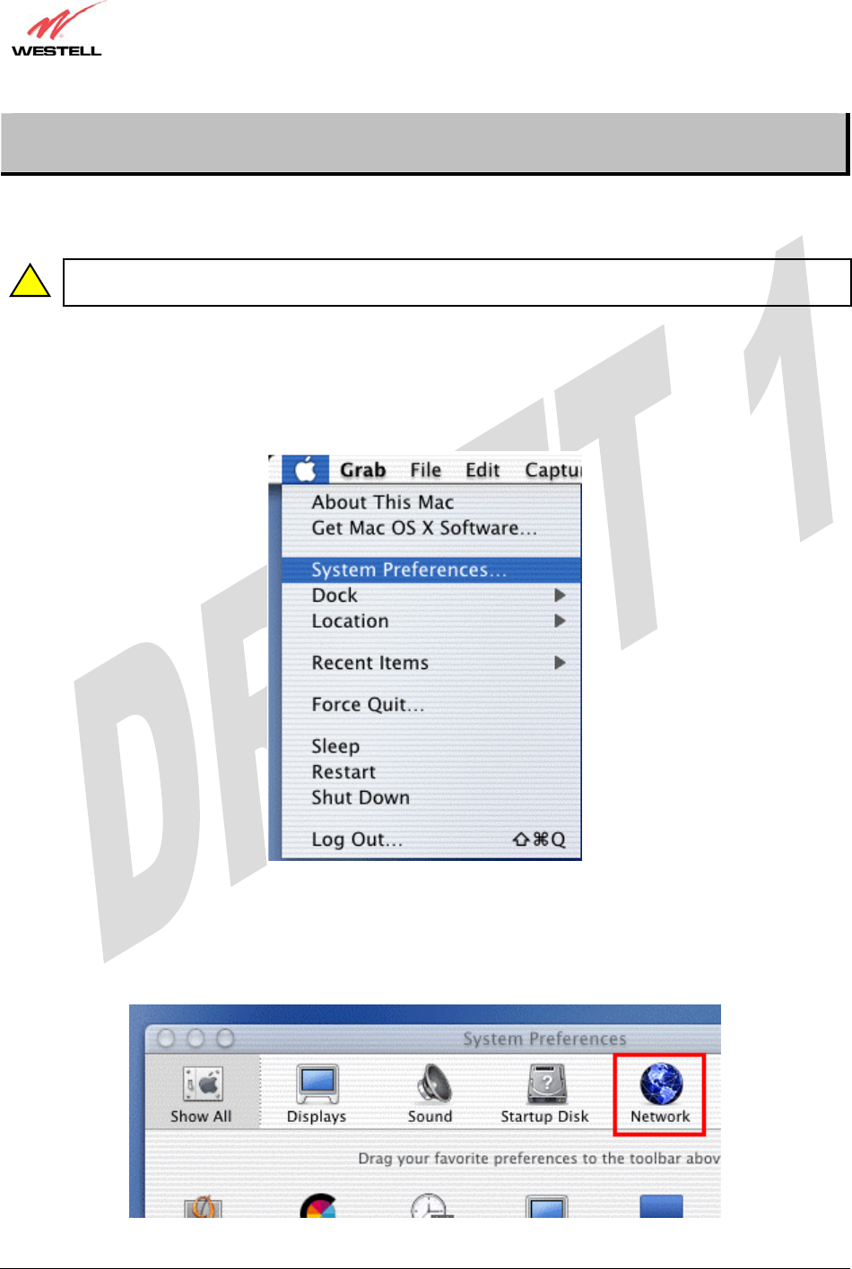
Open the System Preference Screen
After you have connected the Westell Gateway to the Ethernet port of your Macintosh, the screen below will appear.
Click on the “Apple” icon in the upper-right corner of the screen and select System Preferences.
Choose the Network Preferences
After selecting System Preferences…, from the previous screen, the System Preferences screen will be displayed.
From the System Preferences screen, click on the Network icon.
!
030-300479 Rev. A
Draft 1 – 10/17/05
030-300479 Rev. A 22 October 2005
User Guide UltraLine IIB (Model A90-816030)
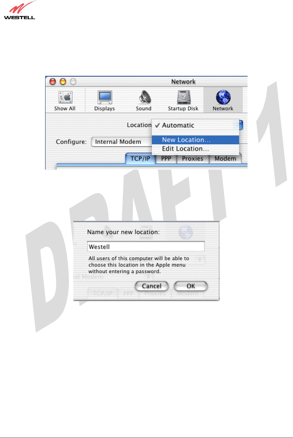
Create a New Location
After selecting the Network icon at the System Preferences screen, the Network screen will be displayed. Select
New Location from the Location field.
Name the New Location
After selecting New Location from the Network screen, the following screen will be displayed. In the field labeled
Name your new location:, change the text from “Untitled” to “Westell.” Click OK.
030-300479 Rev. A
Draft 1 – 10/17/05
030-300479 Rev. A 23 October 2005
User Guide UltraLine IIB (Model A90-816030)
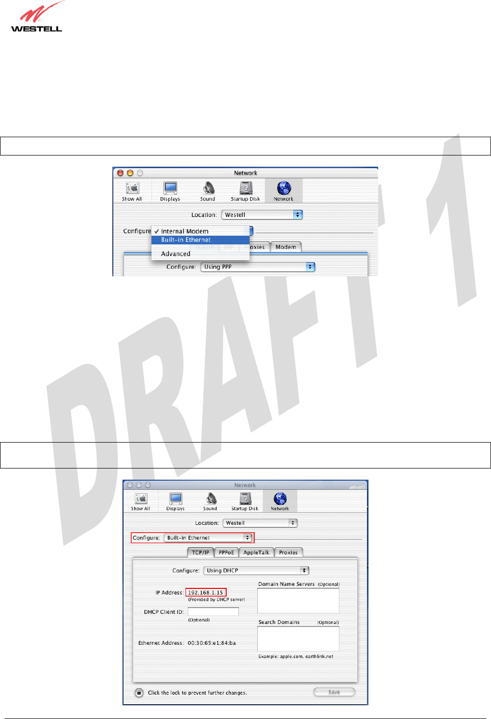
Select the Ethernet Configuration
After clicking on OK in the preceding screen, the Network screen will be displayed. The Network screen shows the
settings for the newly created location. From the Configure field in the Network screen, select Built-in Ethernet.
Click on Save.
NOTE: Default settings for the Built-in Ethernet configuration are sufficient to operate the Gateway.
Check the IP Connection
To verify that the computer is communicating with the Gateway, follow the instructions below.
1. Go to the “Apple” icon in the upper-right corner of the screen and select System Preferences.
2. From the System Preferences screen, click on the Network icon. The Network screen will be displayed.
3. From the Configure field in the Network screen, select Built-in Ethernet.
4. View the IP address field. An IP address that begins with 192.168.1 should be displayed.
NOTE: The DHCP server provides this IP address. If this IP address is not displayed, check the Gateway’s wiring
connection to the PC. If necessary, refer to section 6 for hardware installation instructions.
030-300479 Rev. A
Draft 1 – 10/17/05
030-300479 Rev. A 24 October 2005
User Guide UltraLine IIB (Model A90-816030)
Create a User Account
In the address window of your Internet Explorer web browser, type http://dslrouter/, and then press ‘Enter’ on your
keyboard.
The Connection Overview screen will be displayed. You may now begin your Account Setup. Refer to section 7 of
this User Guide to configure your Westell Gateway for Internet connection.
030-300479 Rev. A
Draft 1 – 10/17/05
030-300479 Rev. A 25 October 2005
User Guide UltraLine IIB (Model A90-816030)
9. BASIC MODE
The following sections explain the basic configurations of your Gateway. The Gateway’s web pages contain a main
navigation menu displayed at the top of the screens. As you navigate through the various pages of the Gateway, the
active page that you have selected from the Main menu will appear in the left corner of the screen. The submenu
options for that page will appear in the left-side navigation menu, as shown below. A red arrow will be displayed
adjacent to the active submenu option. Please note that the values displayed in the screens might differ from the
actual values reported by your Gateway. If you are at a screen and need help, refer to the Help section, displayed on
the right side of the screen. Additional details are displayed in the tables below the screens.
Some screens allow you to change the configurable settings of your Gateway and require that you save the settings.
To save your settings, click the Save button. To discard any changes you have made to the screen, click the Discard
button. If you click the Discard button, the screen will refresh and display the previously saved settings.
Main Menu
Help Section
Active Page
Submenu Options
030-300479 Rev. A
Draft 1 – 10/17/05
030-300479 Rev. A 26 October 2005
User Guide UltraLine IIB (Model A90-816030)
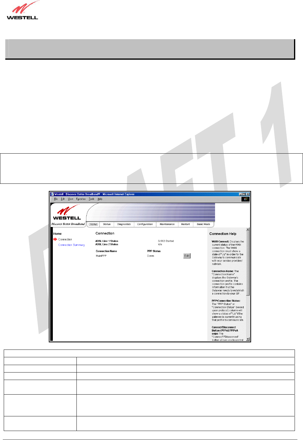
10. HOME
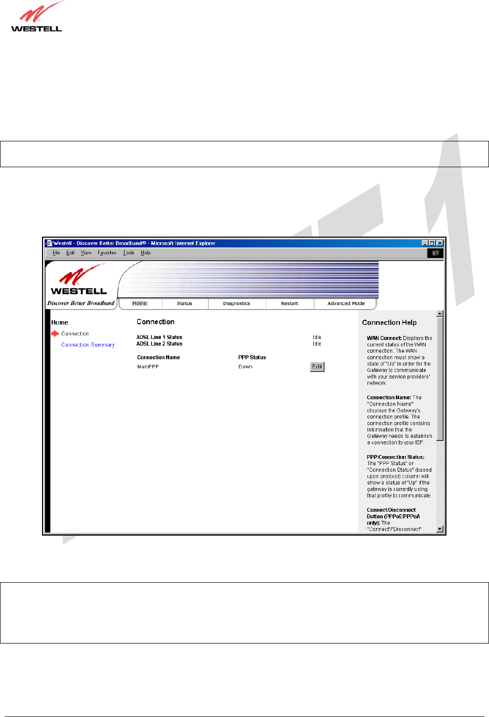
10.1 Connection
After you have set up your account profile and established your PPP session with your Internet service provider
(ISP), as previously discussed in section 7, you are ready to configure your Gateway. The following screen will be
displayed if you select Home > Connection from the menu options.
Description: The Connection screen enables you to view your ADSL and PPP connection status, set up account
profiles (via the Edit button), and establish your PPP session. If needed, please refer to section 7 for details on the
Connection screen. View this screen after you have reset your modem, restarted your PC, or anytime you want to
check the connectivity status of the UltraLine IIB connections.
NOTE: The following screen displays “MainPPP” as the active connection profile. This is the factory default profile
that you must use to establish a PPP session with your ISP. After you have established a PPP session, you may use
other connection profiles that you may have created via the Edit button. Refer to section 7.2 for details on setting up a
connection profile.
Connection
ADSL Line 1 Status Displays the connectivity status of ADSL Line 1.
ADSL Line 2 Status Displays the connectivity status of ADSL Line 2.
Connection Name The Connection Name is from the connection profile that you set up in section 7.2.
PPP Status Up = PPP session established
Down = No PPP session established.
Connect/Disconnect Click Connect to establish a PPP session.
Click Disconnect to disconnect a PPP session
Note: This button will not be displayed until a DSL sync has been established.
Edit Click Edit to add or edit a connection profile. Refer to section 7.2 for details on
connections profiles.
030-300479 Rev. A
Draft 1 – 10/17/05
030-300479 Rev. A 27 October 2005
User Guide UltraLine IIB (Model A90-816030)
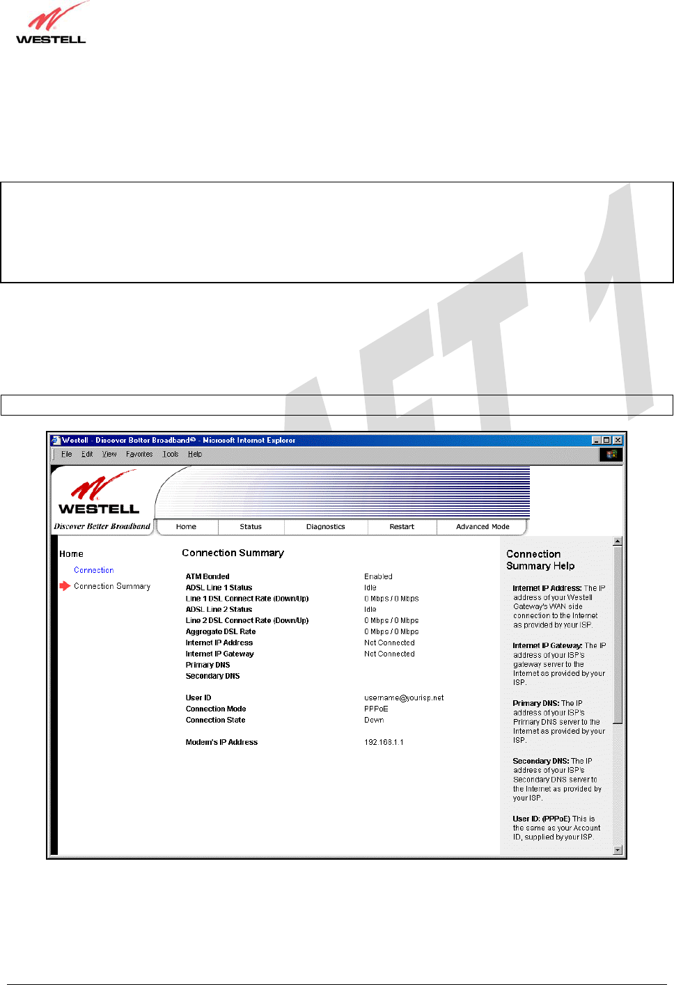
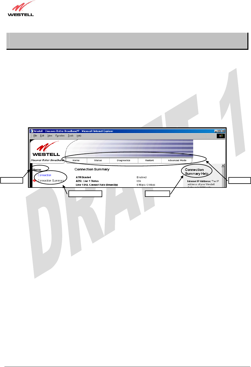
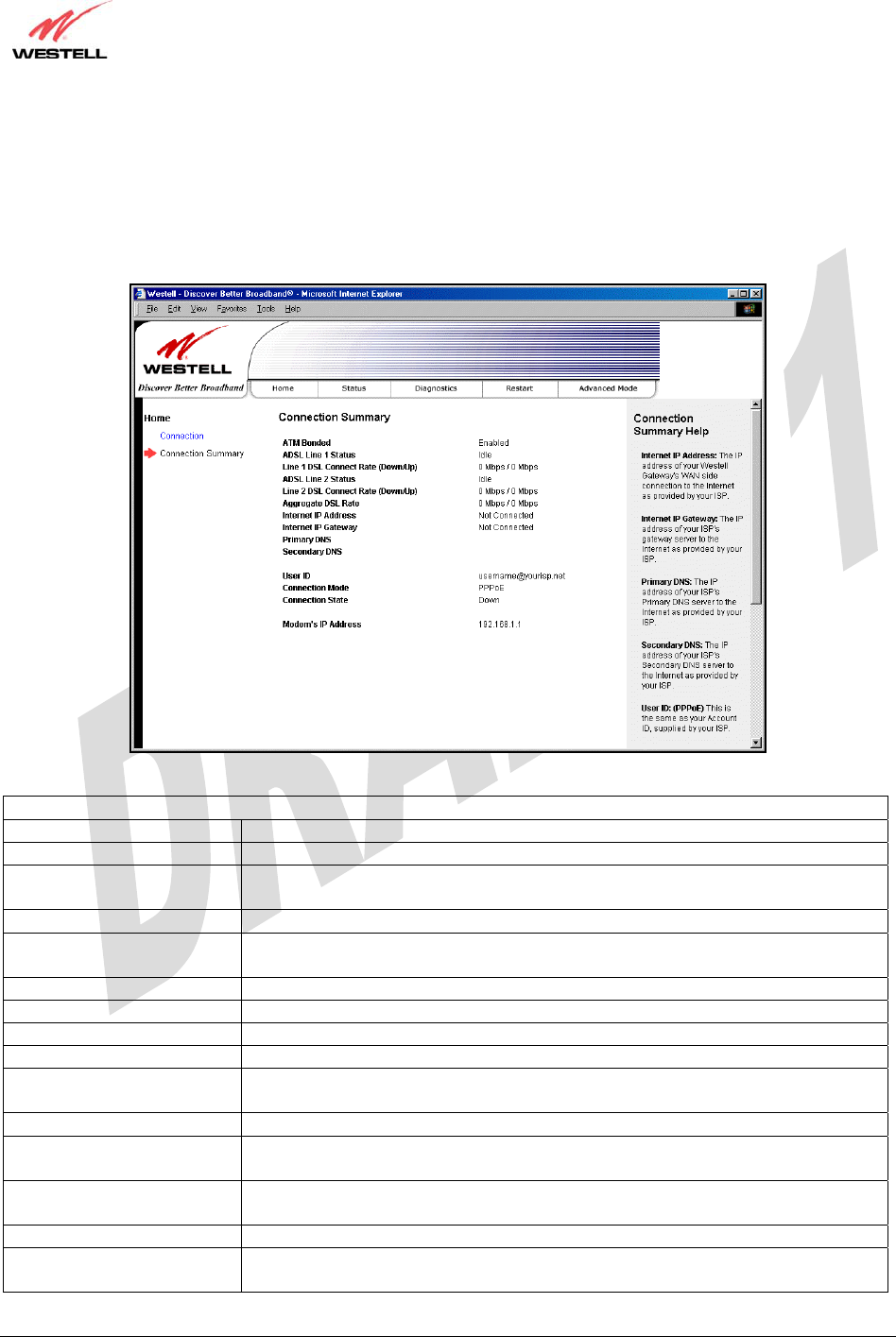
10.2 Connection Summary
The following screen will be displayed if you select Home > Connection Summary from the menu options.
Description: The Connection Summary screen displays general information about your Gateway’s ADSL
connection.
Connection Summary
ATM Bonded Indicates whether the ATM Bonded feature is enabled or disabled.
ADSL Line 1 Status Displays the connectivity status of ADSL Line 1.
Line 1 DSL Connect Rate
(Down/Up) The transmission speed of ADSL Line 1.
ADSL Line 2 Status Displays the connectivity status of ADSL Line 2.
Line 2 DSL Connect Rate
(Down/UP) The transmission speed of ADSL Line 2.
Aggregate DSL Rate The combined transmission speed of the two lines (DSL1 and DSL2).
Internet IP Address The WAN side or Gateway’s IP address to the Internet. Provided by your ISP.
Internet IP Gateway The IP address of your ISP’s server to the Internet. Provided by your ISP.
Primary DNS The IP address of your ISP’s primary DNS server. Provided by your ISP.
Secondary DNS The IP address of your ISP’s secondary DNS server. Provided by your Internet
service provider.
User ID The same as your Account ID. Provided by your ISP.
Connection Mode The Gateway’s mode of connection to your ISP. This can be PPPoE, PPPoA,
Bridge, or IP.
Connection State The Gateway’s PPP connectivity status to the Internet. The DSL status must be up
in order for the PPP connectivity to be up.
Modem’s IP Address The IP Address on the LAN side of your Gateway.
Ethernet Status The Gateway’s LAN-side Ethernet connection status. This is the Ethernet status
between the Gateway and your computer.
030-300479 Rev. A
Draft 1 – 10/17/05
030-300479 Rev. A 28 October 2005
User Guide UltraLine IIB (Model A90-816030)
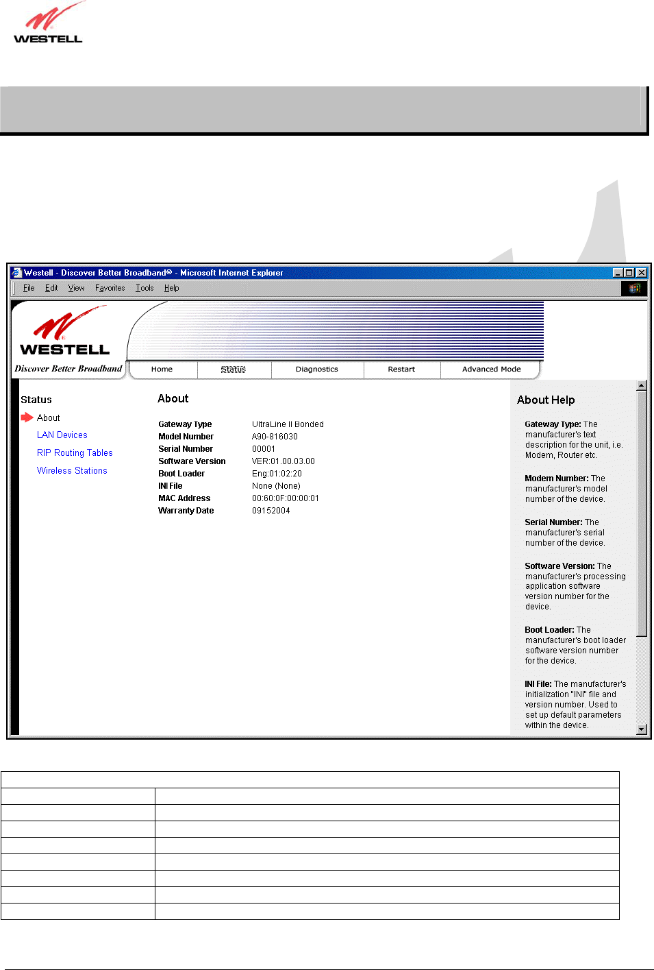
11. STATUS
11.1 About
The following screen will be displayed if you select Status > About from the menu options.
Description: The About screen displays general manufacturer’s information about your Gateway.
About
Gateway Type The manufacturer’s modem name.
Model Number The manufacturer’s model number.
Serial Number The manufacturer’s serial number.
Software Version The version of the application software and the build date.
Boot Loader The manufacturer’s boot load number.
INI File The Gateway manufacturer’s INI information.
MAC Address Media Access Controller (MAC) i.e., hardware address of this device.
Warranty Date The start date of the modem’s warranty
030-300479 Rev. A
Draft 1 – 10/17/05
030-300479 Rev. A 29 October 2005
User Guide UltraLine IIB (Model A90-816030)
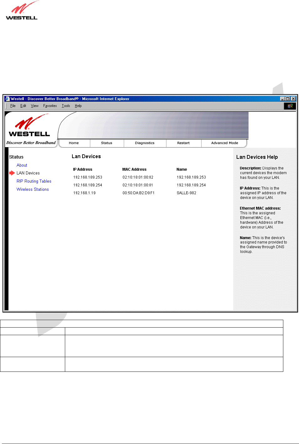
11.2 LAN Devices
The following screen will be displayed if you select Status > LAN Devices from the menu options.
Description: The LAN Devices screen displays all the devices associated with your the LAN (via physical or
wireless connections).
LAN Devices
IP Address The assigned IP address of the networking device.
MAC Address The Ethernet media access controller (MAC) address of the networking device (i.e.,
the hardware address). This is a unique number entered into the device’s permanent
memory during production.
Name The computer’s assigned name. (The computer name or the IP address may be
displayed in this field.)
030-300479 Rev. A
Draft 1 – 10/17/05
030-300479 Rev. A 30 October 2005
User Guide UltraLine IIB (Model A90-816030)
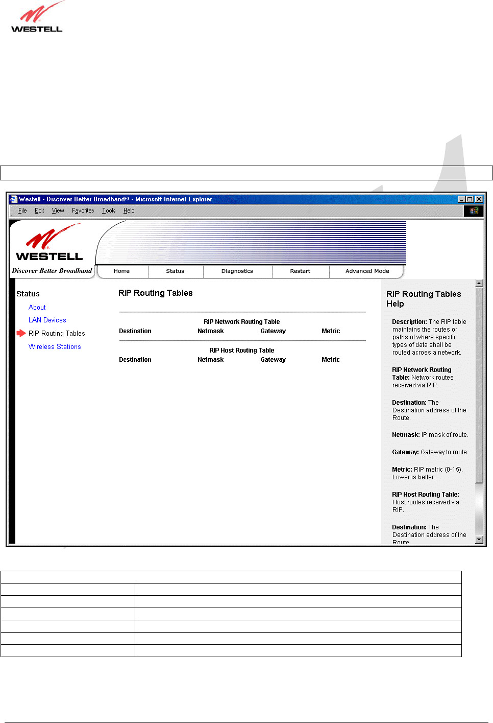
11.3 RIP Routing Tables
The following screen will be displayed if you select Status > RIP Routing Tables from the menu options.
Description: RIP (Routing Information Protocol) is a dynamic inter-network routing protocol primarily used in
interior routing environments. It is a dynamic routing protocol that automatically discovers routes and builds routing
tables, as opposed to a static routing protocol.
NOTE: RIP must be enabled for this table to be populated with data.
RIP Routing Tables
RIP Network Routing Table Indicates Network routes received via RIP.
RIP Host Routing Table The Host routes received via RIP.
Destination The destination IP address of the route
Netmask The IP mask of the route
Gateway The gateway of the route
Metric The RIP metric (0-15). A lower value is better.
030-300479 Rev. A
Draft 1 – 10/17/05
030-300479 Rev. A 31 October 2005
User Guide UltraLine IIB (Model A90-816030)
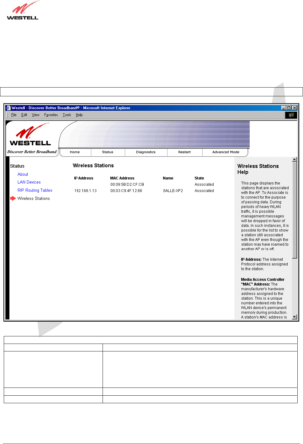
11.4 Wireless Stations
The following screen will be displayed if you select Status > Wireless Stations from the menu options.
Description: Displays information about the wireless stations (devices) that are associated with your Gateway.
NOTE: The fields in this screen will be blank if no stations are associated with your Gateway.
Wireless Stations
IP Address The IP address of the station associated with the Gateway.
MAC Address The Media Access Controller (MAC) address (i.e., the hardware address
of the associated station). This is a unique number entered into the WLAN
device’s permanent memory during production. A station’s MAC address
is typically printed on the card or can be viewed using the card’s
configuration utility.
Name The name of the station associated with the Gateway.
State Indicates the station’s wireless connectivity state.
030-300479 Rev. A
Draft 1 – 10/17/05
030-300479 Rev. A 32 October 2005
User Guide UltraLine IIB (Model A90-816030)
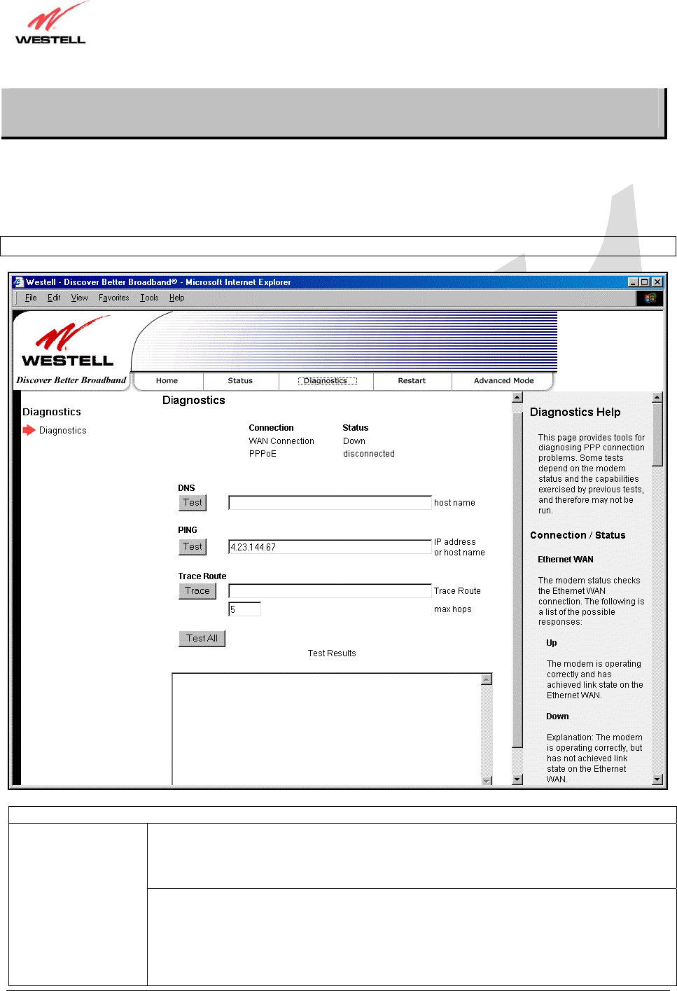
12. DIAGNOSTICS
The following screen will be displayed if you select Diagnostics from the menu options.
Description: Allows you to perform simple diagnostics on your Gateway and to test your connectivity to other
networking devices.
NOTE: This function is not be available if your Gateway is in Bridge mode.
Connection/Status
The first line displays the physical interface used.
Possible Responses:
DSL
Ethernet WAN
Connection The second line displays the Protocol used to establish the session.
Possible Responses:
PPPoE
PPPoATM
RoutedBridge
Bridge

030-300479 Rev. A
Draft 1 – 10/17/05
030-300479 Rev. A 33 October 2005
User Guide UltraLine IIB (Model A90-816030)
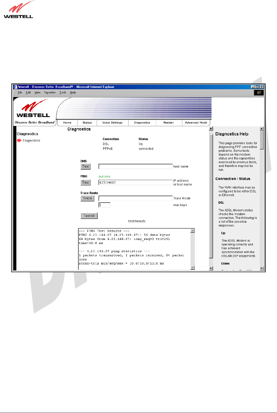
The first line displays the status of the physical interface connection
Possible Responses:
UP – The interface connection is Up.
Down – The interface connection is Down.
Status The second line indicates the status of the Protocol used.
Possible Responses:
Connected – The protocol is connected.
Disconnected – The protocol is disconnected.
Test Description / Test Results
DNS Performs a test to try to resolve the name of a particular host. The host name is entered in
the input box.
Possible responses are:
Success: The Gateway has successfully obtained the resolved address. The IP address is
shown below the host name input box.
No Response: The Gateway has failed to obtain the resolved address.
Host not found: The DNS Server was unable to find an address for the given host name.
No data, enter host name: No host name is specified.
Could not test: The test could not be executed due to the Gateway’s settings. Check your
DSL sync or your PPP session. You must have both a DSL sync and a PPP connection
established to execute a PING.
IP Address IP Address of the Host Name.
PING
(via IP Address or
Host Name)
Performs an IP connectivity check to a remote computer either within or beyond the
Service Provider’s network. You can PING a remote computer via the IP address or the
DNS address. If your PING fails, try a different IP or DNS address.
Possible responses are:
Success: The Remote Host computer was detected.
No Response: There was no response to the Ping from the remote computer.
No name or address to PING: No host name or IP address was specified.
Could not test: The test could not be executed due to the Gateway settings. Check your
DSL sync or your PPP session. You must have both a DSL sync and a PPP connection
established to execute a PING.
Trace Route
Determines the route taken to destination by sending Internet Control Message Protocol
(ICMP) echo packets with varying IP Time-To-Live (TTL) values to the destination. Trace
Route is used to determine where the packet is stopped on the network.
Max hops The number of hops from the Gateway to the specified destination.
Test All Allows you to run a full diagnostic test.
030-300479 Rev. A
Draft 1 – 10/17/05
030-300479 Rev. A 34 October 2005
User Guide UltraLine IIB (Model A90-816030)
• To run a DNS test, type the appropriate host name in the field provided, and then click Test.
• To run a PING test, type the appropriate IP address or host name in the field provided, and then click Test.
• To run a Trace Route, type the appropriate IP address or host name in the field provided, and then click Trace.
If you click Test All, the following screen will display the results in the window labeled Test Results.
030-300479 Rev. A
Draft 1 – 10/17/05
030-300479 Rev. A 35 October 2005
User Guide UltraLine IIB (Model A90-816030)
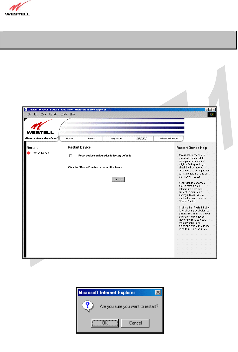
13. RESTART
The following screen will be displayed if you select Restart from the menu options.
Description: Allows you to restart your Gateway and either keep or erase the Gateway’s current configuration
settings. To erase the current configuration and reset the Gateway to the factory default settings, click the check box
labeled Reset device to configuration to factory defaults prior to clicking the Restart button; all custom
configuration information will be erased. If you want to retain your current configurations while restarting the
Gateway, leave the box unchecked and simply click Restart.
After you click Restart, the following pop-up screen will be displayed. Click OK to continue. Click Cancel if you
do not want to restart the Gateway.
030-300479 Rev. A
Draft 1 – 10/17/05
030-300479 Rev. A 36 October 2005
User Guide UltraLine IIB (Model A90-816030)
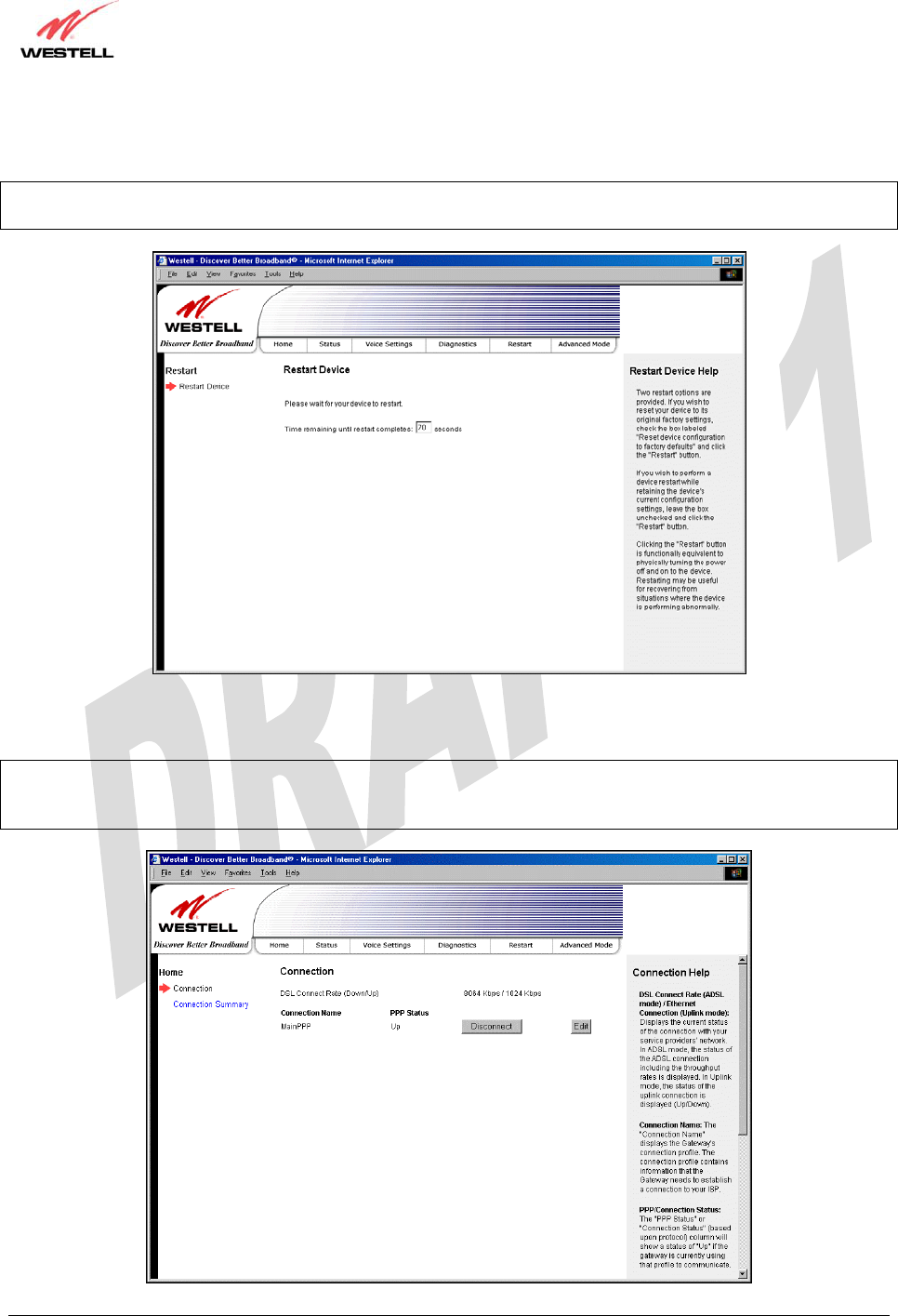
If you clicked OK in the preceding pop-up screen, the following screen will be displayed. Please wait for your
Gateway to restart. After your Gateway has restarted, the Edit Connection screen will be displayed.
NOTE: You may hear a click in the modem during restart. Please do not be alarmed as this will occur whenever the
Gateway restarts.
At the Edit Connection screen, confirm that the PPP Status field displays “Up” before proceeding with your
Gateway’s configuration.
NOTE: If you have chosen to reset the modem to the factory default configuration, you must set up your account
profile and establish your connection as previously explained in section 7, “Configuring the Gateway for Internet
Connection.”
030-300479 Rev. A
Draft 1 – 10/17/05
030-300479 Rev. A 37 October 2005
User Guide UltraLine IIB (Model A90-816030)
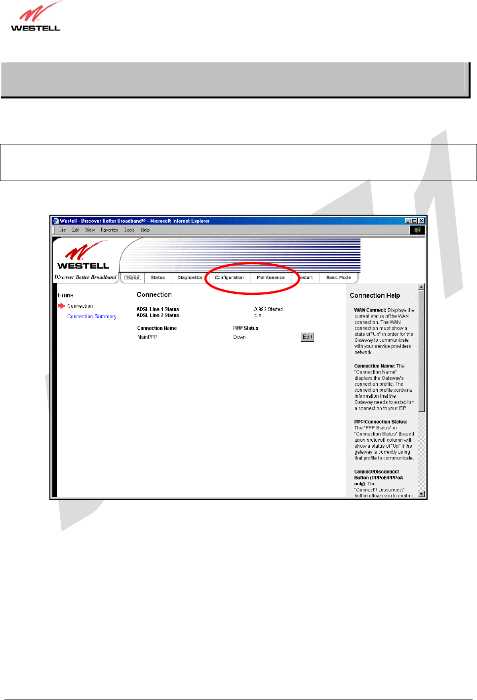
14. ADVANCED MODE
The following screen will be displayed if you select Advanced from the menu options (if you are currently in Basic
Mode).
NOTE: The basic operations of your Gateway were discussed earlier in this User Guide and provided details on the
Home, Status, Diagnostics, and Restart features. For instructions on configuring any of these features, refer to the
Basic Mode sections (beginning with section 9) of this User Guide.
The advanced features of your Gateway will be discussed in sections 15, 16, and 17.
030-300479 Rev. A
Draft 1 – 10/17/05
030-300479 Rev. A 38 October 2005
User Guide UltraLine IIB (Model A90-816030)
15. CONFIGURATION
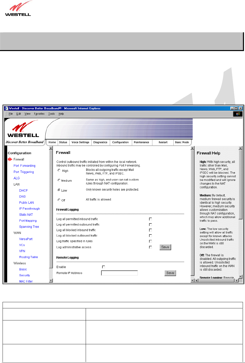
15.1 Firewall Configuration
The following screen will be displayed if you select Configuration > Firewall from the menu options. If you change
any settings in this screen, you must click Save to save the settings.
Description:
Security Level
High High security level only allows basic Internet functionality. Only Mail,
News, Web, FTP, and IPSEC are allowed. All other traffic is prohibited.
Medium Like High security, Medium security only allows basic Internet
functionality by default. However, Medium security allows
customization through NAT configuration so that you can enable the
traffic that you want to pass.
Low Factory Default = Low
The Low security setting will allow all traffic except for known attacks.
If securit
y
is set to Low, the Gatewa
y
will be visible to other com
p
uters

030-300479 Rev. A
Draft 1 – 10/17/05
030-300479 Rev. A 39 October 2005
User Guide UltraLine IIB (Model A90-816030)
on the Internet.
Off Firewall is disabled. (All traffic is passed)
Firewall Logging
Log all permitted inbound traffic Factory Default = Disabled
If Enabled (box is checked), this function will be activated.
Log all permitted outbound traffic Factory Default = Disabled
If Enabled (box is checked), this function will be activated.
Log all blocked inbound traffic Factory Default = Disabled
If Enabled (box is checked), this function will be activated.
Log all blocked outbound traffic Factory Default = Disabled
If Enabled (box is unchecked), this function will be activated.
Log traffic specified in rules Factory Default = Disabled
If Enabled (box is checked), this function will be activated.
Log administrative access Factory Default = Disabled
If Enabled (box is checked), this function will be activated.
Remote Logging
Enable Factory Default = Disable
If Enabled (box is checked), the Gateway will send firewall logs to a
syslog server.
Remote IP Address The IP address of the syslog server machine to which the diagnostics logs
to be sent.
030-300479 Rev. A
Draft 1 – 10/17/05
030-300479 Rev. A 40 October 2005
User Guide UltraLine IIB (Model A90-816030)
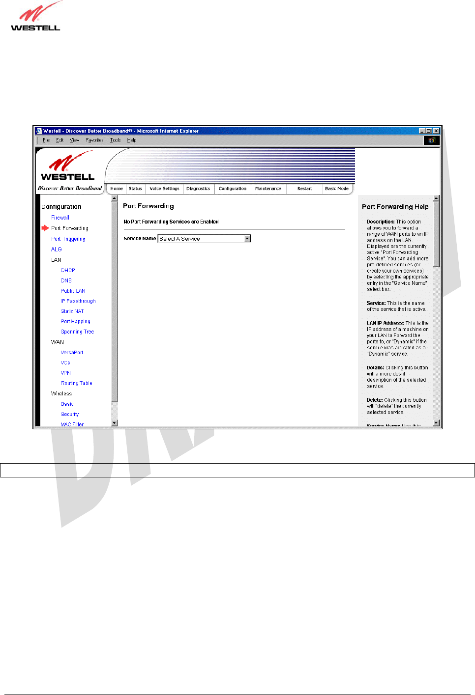
15.2 Port Forwarding Configuration
The following screen will be displayed if you select Port Forwarding from the Configuration menu. Port
Forwarding enables you to set up the Gateway’s port forwarding attributes for the services you add to your profile.
To set up port forwarding, select a service from the Service Name drop-down menu.
NOTE: You may add an unlimited numbers of services to your profile.
030-300479 Rev. A
Draft 1 – 10/17/05
030-300479 Rev. A 41 October 2005
User Guide UltraLine IIB (Model A90-816030)
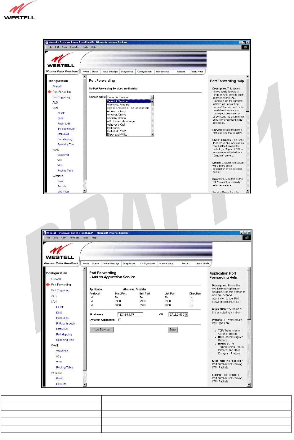
After you have selected a service name from the Service Name drop-down menu, the following Port Forwarding –
Add an Application Service screen will be displayed. Enter the appropriate IP address or machine name in the fields
provided and then click Add Service. Repeat these steps to add additional services to your profile.
Application Protocol The IP Protocol type that is assigned to this service.
Start Port The start port that is assigned to the service
End Port The end port that is assigned to the service
LAN Port The LAN port that is assigned to the service.
Direction The traffic direction assigned to the service.
030-300479 Rev. A
Draft 1 – 10/17/05
030-300479 Rev. A 42 October 2005
User Guide UltraLine IIB (Model A90-816030)
IP Address The LAN IP address or the machine name assigned to your service
Dynamic Application Factory Default = Disabled
If Enabled (box is checked), this will only allow outgoing connections
from any local PC.
If Disabled, packets will be forwarded to the designated local PC.
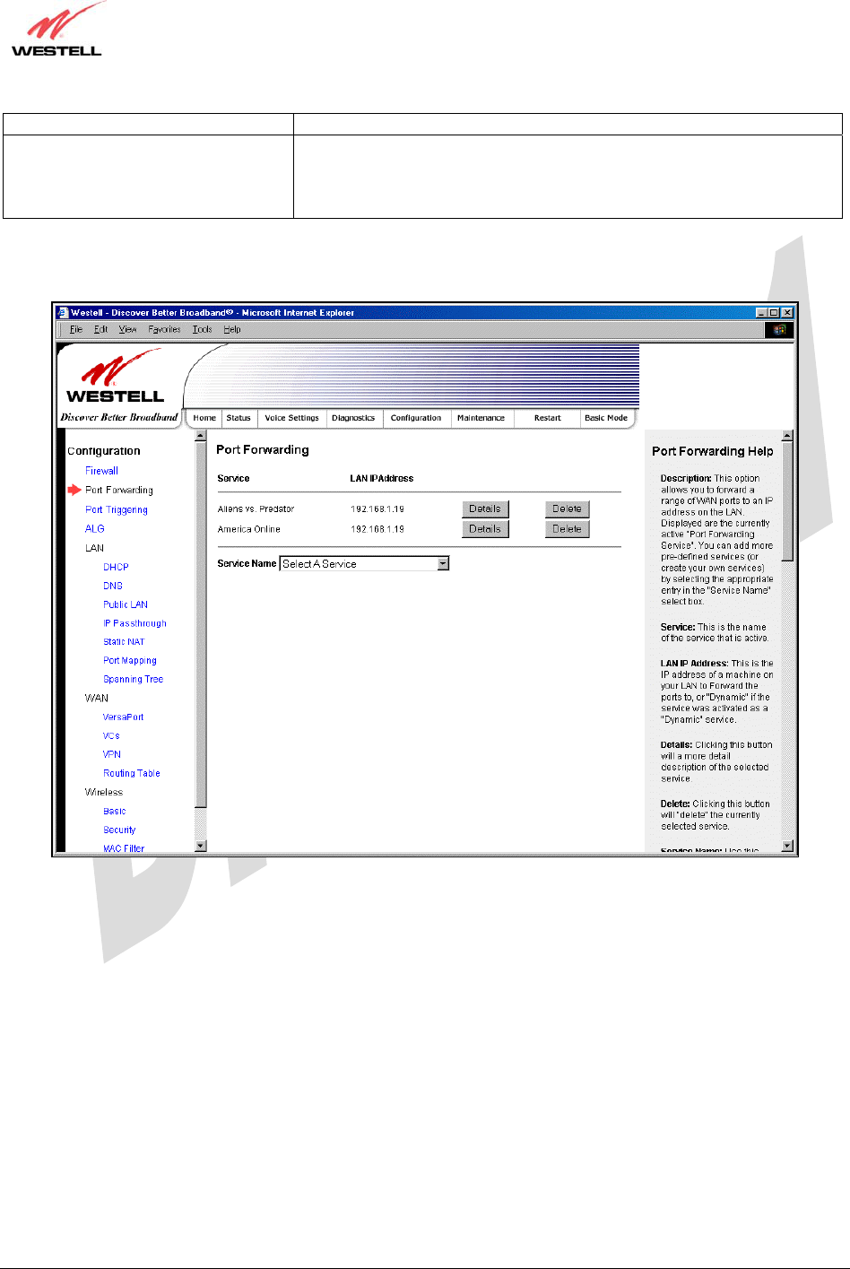
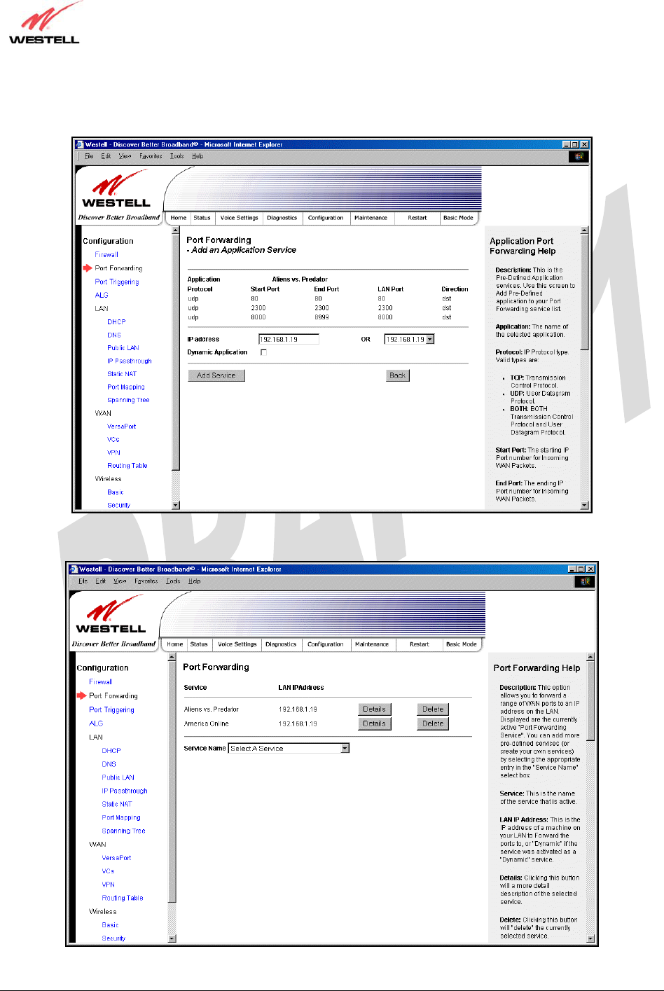
If you clicked Add Service, the following screen will be displayed. To view the details of a service you have added,
click the Details button adjacent to the service you want to view.
030-300479 Rev. A
Draft 1 – 10/17/05
030-300479 Rev. A 43 October 2005
User Guide UltraLine IIB (Model A90-816030)
If you clicked the Details button, the following screen will be displayed. After viewing the details of your service,
click Back to return to the preceding Port Forwarding screen.
To delete a service that you have added, click the Delete button adjacent to the service you want to remove.
030-300479 Rev. A
Draft 1 – 10/17/05
030-300479 Rev. A 44 October 2005
User Guide UltraLine IIB (Model A90-816030)
If you clicked Delete in the preceding screen, the following pop-up screen will be displayed. Click OK in the pop-
up screen; the service will then be removed from the list of selected services. Click Cancel if you do not want to
delete the selected service.
15.3 Port Triggering
The following screen will be displayed if you select Port Triggering from the Configuration menu. To create a trigger
port, click New.
030-300479 Rev. A
Draft 1 – 10/17/05
030-300479 Rev. A 45 October 2005
User Guide UltraLine IIB (Model A90-816030)
If you clicked New, the following screen will be displayed. Select the desired options from the drop-down menus,
and then enter the appropriate values in the fields provide. Click Save to save your settings.
Port Triggering Configuration
Outgoing Protocol Factory Default = TCP
The outgoing protocol for the triggered ports.
Possible Response:
TCP – Transmission Control Protocol
UDP – User Datagram Protocol
Outgoing Port Start The WAN-side TCP/UDP starting port
Outgoing Port End The WAN-side TCP/UDP ending port
Incoming Protocol Factory Default = TCP
The incoming protocol for the triggered ports.
Possible Response:
TCP- Transmission Control Protocol
UDP- User Datagram Protocol
Both – TCP and UDP
Incoming Port Start The local LAN-side starting port.
Incoming Port End The local LAN-side ending port.
030-300479 Rev. A
Draft 1 – 10/17/05
030-300479 Rev. A 46 October 2005
User Guide UltraLine IIB (Model A90-816030)
15.4 ALG Configuration
The following screen will be displayed if you select ALG from the Configuration menu. This page enables you to
configure ALG services for your Gateway. Click on the box of each service that you want to enable (a check mark
will appear in the box), and then click Save to save the settings.
NOTE: When the firewall level is set to “High,” some services may not be configurable.
ALG
Name The name of the ALG service.
Enabled To enable the service, click on the adjacent box (a check mark will appear in the box).
To disable the service, click to uncheck the box.
030-300479 Rev. A
Draft 1 – 10/17/05
030-300479 Rev. A 47 October 2005
User Guide UltraLine IIB (Model A90-816030)
15.5 LAN Configuration
15.5.1 DHCP
The following screen will be displayed if you select LAN > DHCP from the Configuration menu. This page enables
you to control how the Gateway interacts with local devices to which it is connected. Enter the appropriate values,
and then click Save to save your settings.
NOTE: Westell recommends that you do not change these settings unless instructed by your Internet service
provider.
DHCP Configuration for Private LAN
Enable DHCP Server Factory Default = Enable
This setting allows the Gateway to automatically assign IP addresses to local devices
connected on the LAN. Westell advises setting this to enabled for the private LAN.
Private LAN = DHCP addresses will be saved into the Private LAN configuration.
Public LAN = DHCP addresses will be saved into the Public LAN configuration. (This
option is only available if the Public LAN DHCP server is enabled.)
Possible Response:
If this box is checked, the DHCP server will be turned On.
If this box is unchecked, the DHCP server will be turned Off.
Note: These addresses will be overwritten if the Internet Service Provider supports
dynamic setting of these values.
Modem IP Address The IP Address of the Gateway
Subnet Mask The Subnet Mask of the Gateway
Address Range
DHCP Start Address Factory Default = 192.168.1.10
030-300479 Rev. A
Draft 1 – 10/17/05
030-300479 Rev. A 48 October 2005
User Guide UltraLine IIB (Model A90-816030)
This field displays the first IP address that the DHCP server will provide. The DHCP
Start Address must be within the router’s subnet IP and lower than the DHCP End
Address. You may use any number from 0 to 254 in this address.
DHCP End Address Factory Default = 192.168.1.20
This field displays the last IP address that the DHCP server will provide. The DHCP
End Address must be within the router’s subnet IP and higher than the DHCP Start
Address. You may use any number from 0 to 254 in this address.
DHCP Lease Time Factory Default = 01:00:00:00
Displays the amount of time the provided addresses will be valid, after which the
DHCP client will usually re-submit a request.
Note: DHCP Lease Time is displayed in the format (day:hour:min:sec)*. This value
must be greater than 10 seconds. Seconds must be between 0 and 59, minutes must be
between 0 and 59, and hours must be between 0 and 23.
15.5.2 DNS
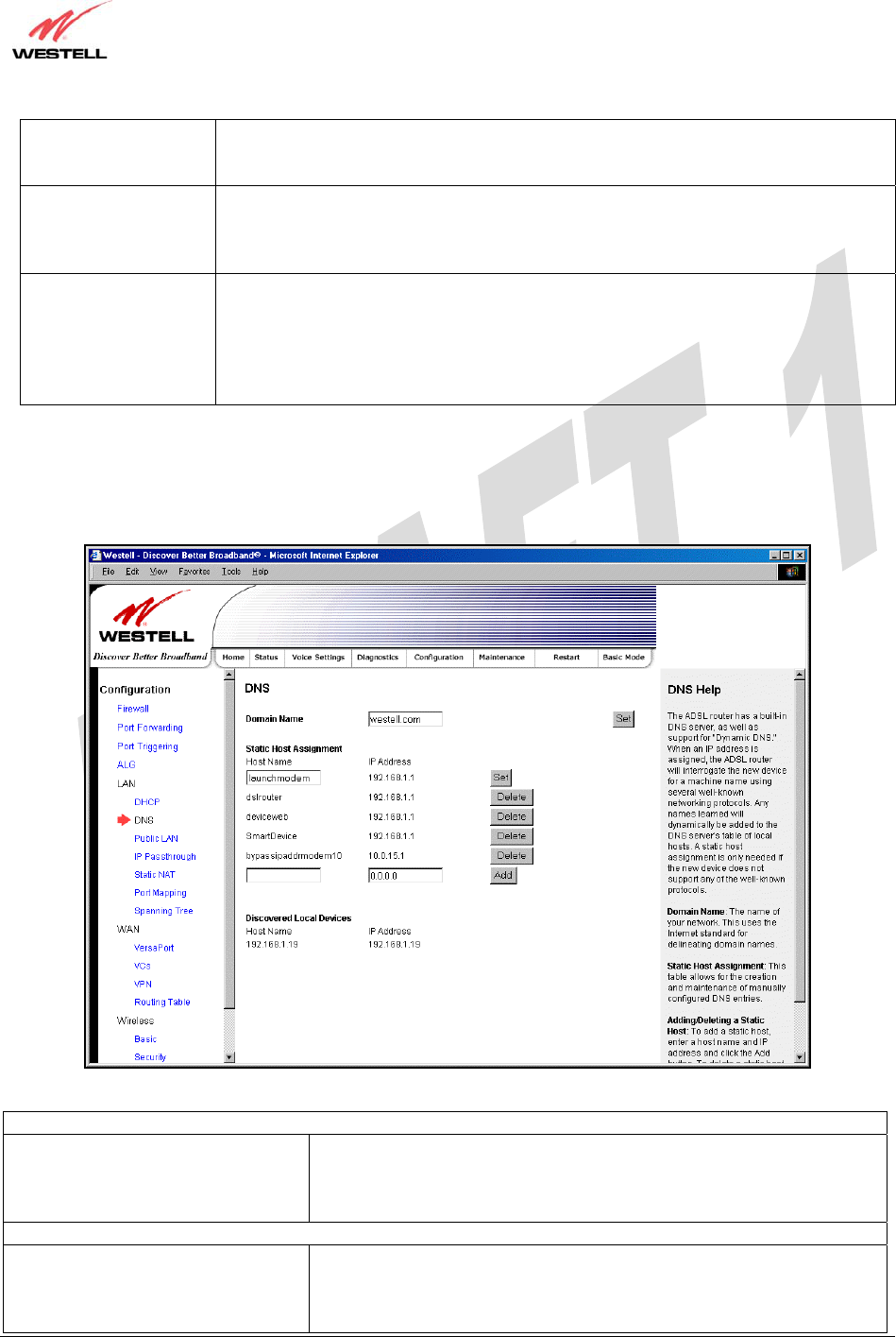
The following screen will be displayed if you select LAN > DNS from the Configuration menu.
DNS
Domain Name
NOTE: Some ISP’s may require the
name for identification purposes.
This field allows you to enter a Domain Name for the Gateway.
To add a Domain Name, in the field under User Assigned DNS, type in
your new domain name and click Set.
Static Host Assignment
Host Name This field allows you to enter a host name for the Gateway.
To add a new host name, in the field under Static Host Assignment, type
in the Host Name and the associated IP address and then click Add.
To delete a Host name, click the Delete button ad
j
acent to the Host Name
030-300479 Rev. A
Draft 1 – 10/17/05
030-300479 Rev. A 49 October 2005
User Guide UltraLine IIB (Model A90-816030)
and IP Address you want to delete.
IP Address Displays the IP address that is assigned to the Host Name.
Discovered Local Devices
This field displays a list of the computers on the LAN that have been assigned a DHCP Address. The DNS name
and IP address entry of each discovered device is displayed. (Note: The values in this field will be displayed
barring any propagation delays. If ‘No Discovered Devices’ is displayed, manually refresh the screen.)
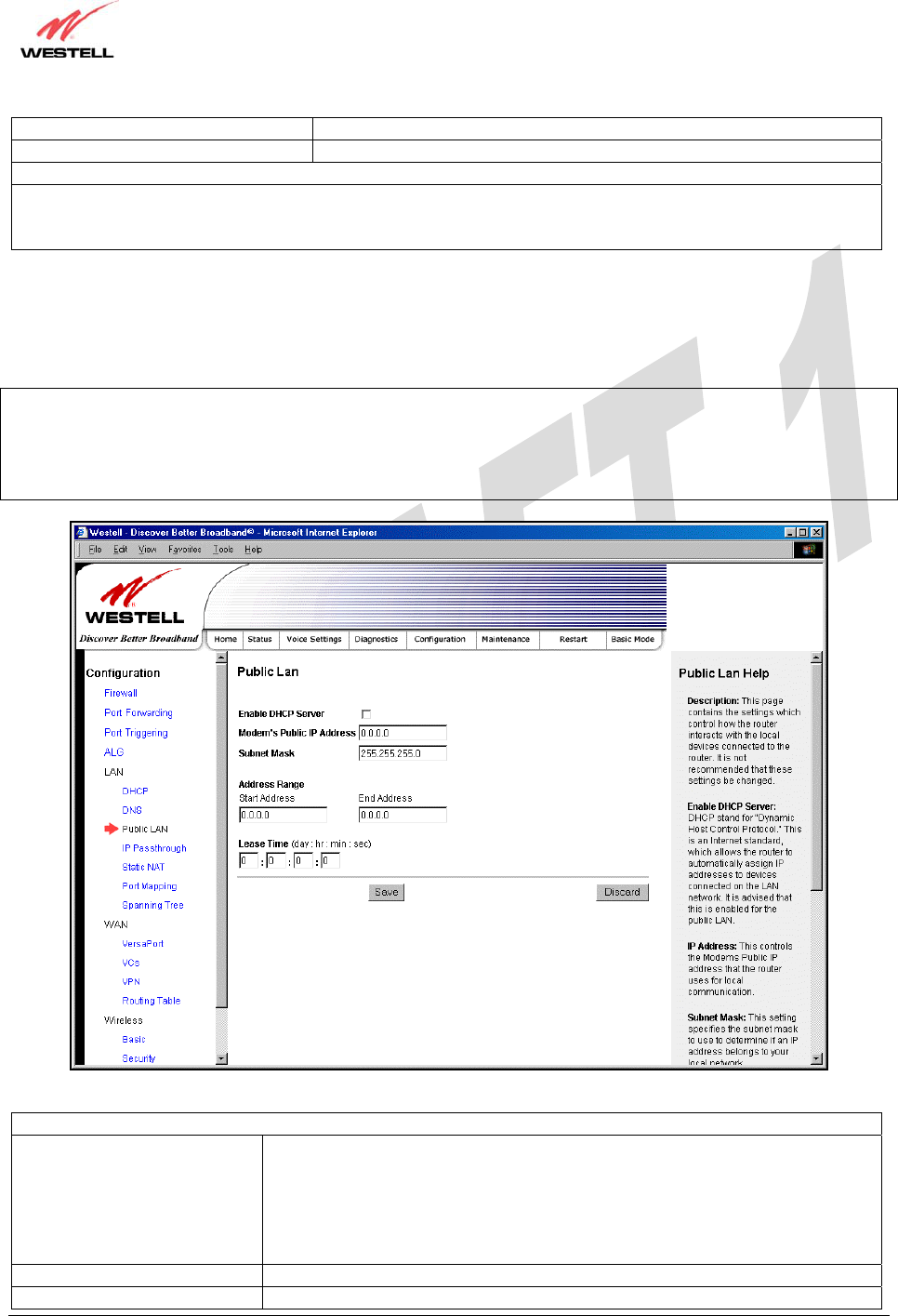
15.5.3 Public LAN – Multiple IP Address Passthrough
The following screen will be displayed if you select LAN > Public LAN from the Configuration menu.
NOTE: Selecting Public LAN will enable the VERSAPORT™2 port to function as an Ethernet LAN port allowing
your Gateway to use LAN IP addresses that accessible from the WAN. This allows your computer to have global
address ability. To use the Public LAN feature on the Gateway, your ISP must support Public LAN and Static IP.
Contact your ISP for details. When VERSAPORT™2 is configured for Public LAN, the Gateway’s DSL transceiver
will be enabled.
Public LAN Settings
Enable DHCP Server Factory Default = Disable
Possible Response:
If Enabled (box is checked), this will enable the Public LAN DHCP server and
allow IP address to be server from the DHCP Public LAN pool.
If Disabled (the box is unchecked), this will disable the Public LAN DHCP
server.
Modem’s Public IP Address The Gateway’s public IP address
Subnet Mask The Subnet Mask, which determines what
p
ortion of an IP address is controlled

030-300479 Rev. A
Draft 1 – 10/17/05
030-300479 Rev. A 50 October 2005
User Guide UltraLine IIB (Model A90-816030)
by the network and which portion is controlled by the host.
Address Range
DHCP Start Address Displays the first IP address that the Public LAN DHCP Server will provide.
The DHCP Start Address must be within the IP address and lower than the
DHCP End Address.
DHCP End Address Displays the last IP address that the Public LAN DHCP Server will provide.
The DHCP End Address must be within the IP address and higher than the
DHCP Start Address.
DHCP Lease Time Factory Default = 01:00:00:00
Displays the amount of time the provided addresses will be valid, after which
time the Public LAN DHCP client will usually re-submit a request.
Note: DHCP Lease Time is displayed in the format (day:hour:min:sec)*. This
value must be greater than 10 seconds. Seconds must be between 0 and 59,
minutes must be between 0 and 59, and hours must be between 0 and 23.
If the settings you have entered in the Public LAN Settings fields are incorrect, the following warnings messages
may be displayed via pop-up screens. If this occurs, check the Public LAN settings.
Warning Message Check Public LAN DHCP Settings
Start Address is not part of the Subnet Check the value in the DHCP Start Address field
End Address is not part of the Subnet Check the value in the DHCP End Address field
End Address is below the Start Address Check the value in the DHCP End Address field
Lease time must be greater than 10 seconds Check the values in the DHCP Lease Time fields
Seconds must be between 0 and 59 Check the Seconds field at DHCP Lease Time
Minutes must be between 0 and 59 Check the Minutes field at DHCP Lease Time
Hours must be between 0 and 23 Check the Hours field at DHCP Lease Time
15.5.4 IP Passthrough – Single IP Address Passthrough
The following screen will be displayed if you select LAN > IP Passthrough from the Configuration menu. IP
Passthrough enables you to select the device on your LAN that will share your Single Static IP address. Before you
begin this section, configure your PC settings to obtain an IP address from your Gateway automatically. (Refer to
your computer’s Windows® Help screen for instructions.)
NOTE: IP Passthrough enables you to share the WAN-assigned IP address with one device on your LAN. Network
Address Translation (NAT) and Firewall rules do not apply to the device configured for IP Passthrough. Thus, the
device with the single static IP address becomes visible on the Internet. If you are using Routed IP protocol, IP
Passthrough configuration will not be available.
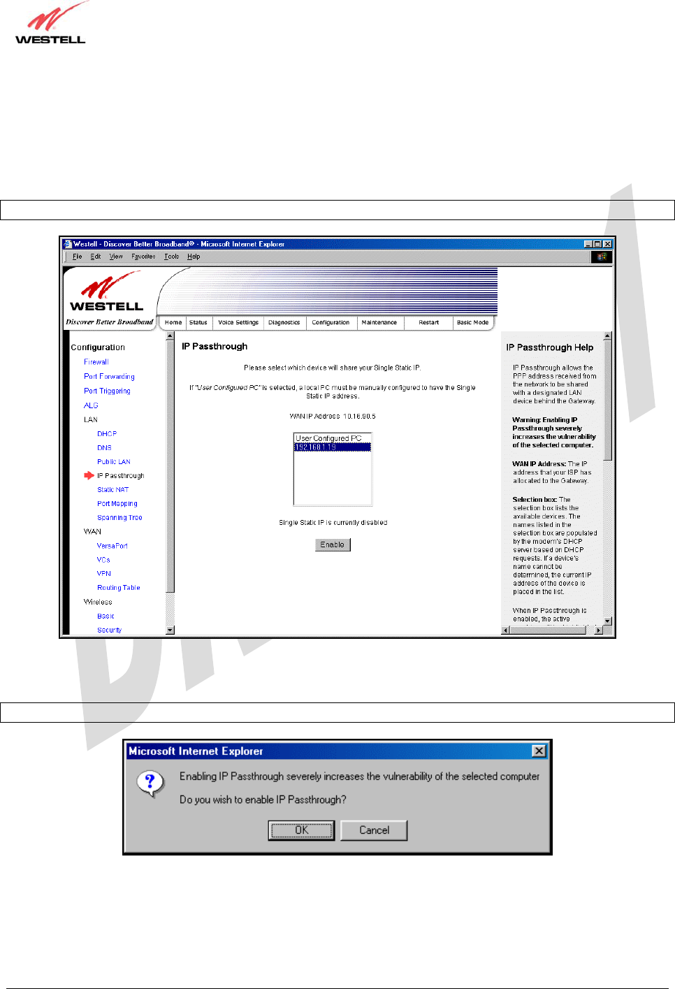
030-300479 Rev. A
Draft 1 – 10/17/05
030-300479 Rev. A 51 October 2005
User Guide UltraLine IIB (Model A90-816030)
15.5.4.1 Enabling IP Passthrough – Single IP Address PassThrough
(Applicable for PPPoE or PPPoA Connections Only)
To enable IP Passthrough, select a device that will share your Single Static IP from the options listed in the window.
Click Enable.
NOTE: The actual device names may differ from the names displayed in this screen.
If you clicked Enable, the following pop-up screen will be displayed. Click OK to continue.
Caution: Enabling IP Passthrough severely increases the vulnerability of the selected computer.
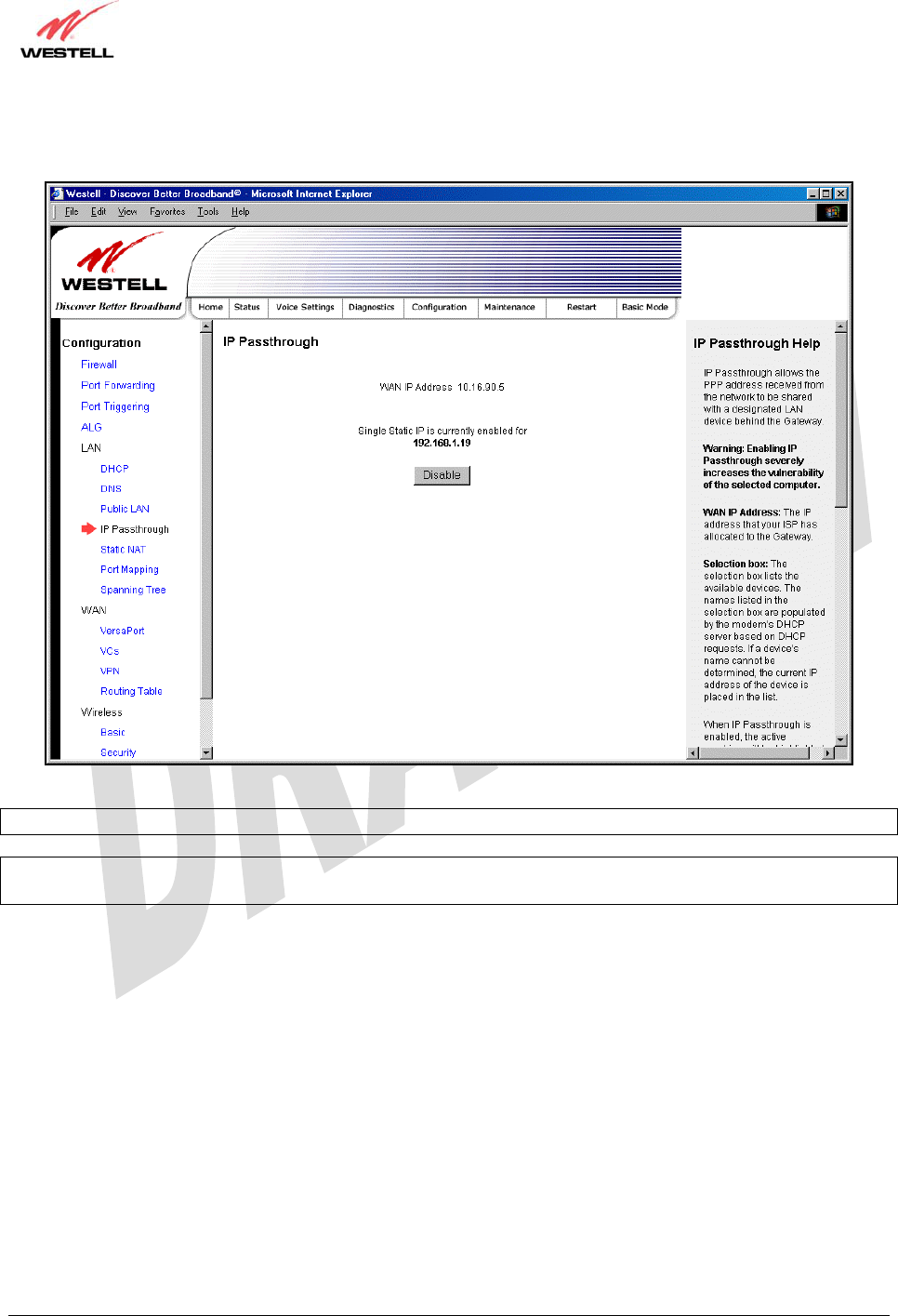
030-300479 Rev. A
Draft 1 – 10/17/05
030-300479 Rev. A 52 October 2005
User Guide UltraLine IIB (Model A90-816030)
If you clicked OK in the preceding pop-up screen, the Gateway will be reset and the new configuration will take
effect, as shown in the following screen.
STOP! After you enable IP Passthrough, you must reboot your computer.
IMPORTANT: If you chose to enable User Configured PC, wait for the Gateway to reset and then manually enter
the WAN IP, Gateway, and Subnet mask addresses you obtained from your Internet service provider into a PC.
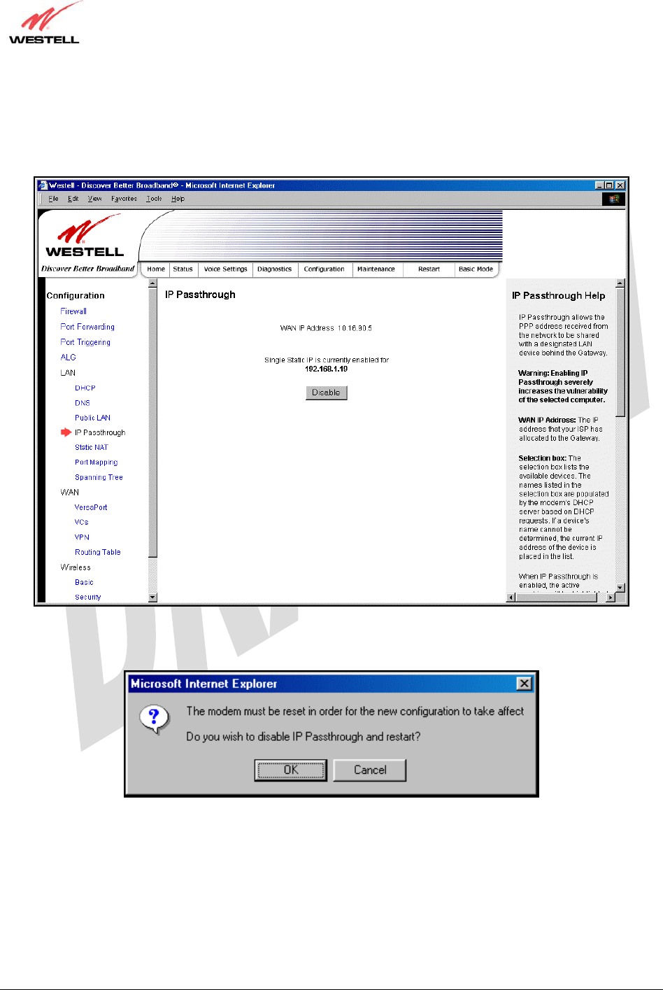
030-300479 Rev. A
Draft 1 – 10/17/05
030-300479 Rev. A 53 October 2005
User Guide UltraLine IIB (Model A90-816030)
15.5.4.2 Disabling IP Passthrough – Single IP Address PassThrough
To disable IP Passthrough (if it has been previously enabled), select IP Passthrough from the Configuration>LAN
menu. Click on Disable.
If you clicked Disable following pop-up screen will be displayed. Click OK to continue.
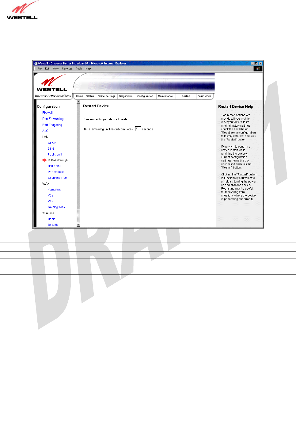
030-300479 Rev. A
Draft 1 – 10/17/05
030-300479 Rev. A 54 October 2005
User Guide UltraLine IIB (Model A90-816030)
If you clicked OK in the preceding pop-up screen, the following screen will be displayed. The Gateway will be reset
and the new configuration will take effect.
STOP! After you disable IP Passthrough, you must reboot your computer.
IMPORTANT: If you chose to enable User Configured PC, wait for the Gateway to reset and then manually enter
the WAN IP, Gateway, and Subnet mask addresses you obtained from your Internet service provider into a PC.
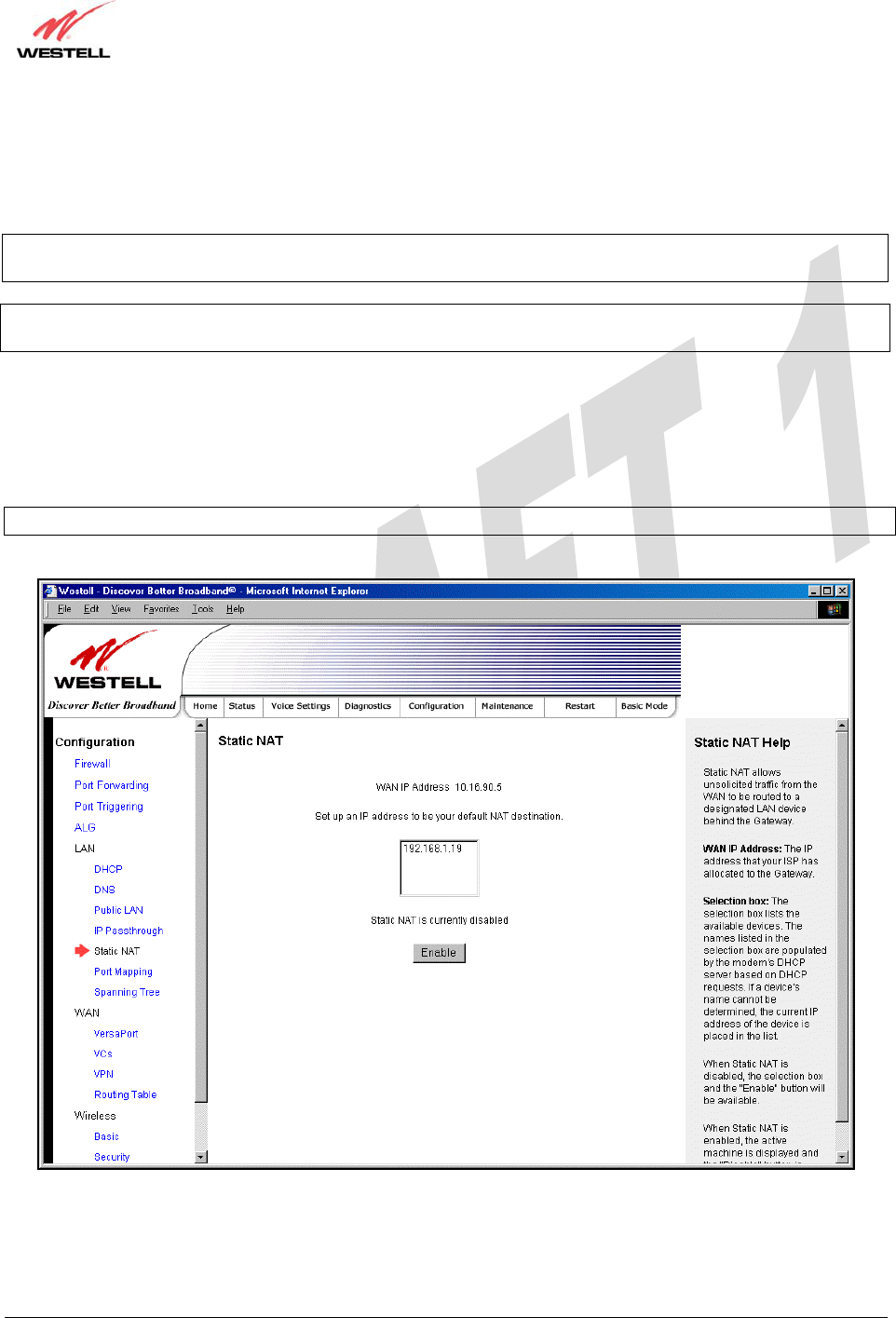
030-300479 Rev. A
Draft 1 – 10/17/05
030-300479 Rev. A 55 October 2005
User Guide UltraLine IIB (Model A90-816030)
15.5.5 Static NAT
The following screen will be displayed if you select LAN > Static NAT from the Configuration menu. This screen
enables you to configure your Gateway to work with the special NAT services.
NOTE: When the Gateway is configured for Static NAT, any unsolicited packets arriving at the WAN would be
forwarded to this device. This feature is used in cases where the user wants to host a server for a specific application.
IMPORTANT: IP Passthough must be disabled (if it has been previously enabled) before you enable static NAT.
Refer to section 15.5.4.2 for instructions on disabling IP Passthrough.
15.5.5.1 Enabling Static NAT
To enable Static NAT, select an IP address or device name from the options listed in the Static NAT screen and then
click Enable.
NOTE: The actual IP addresses or device names may differ from the those displayed in the following screen.
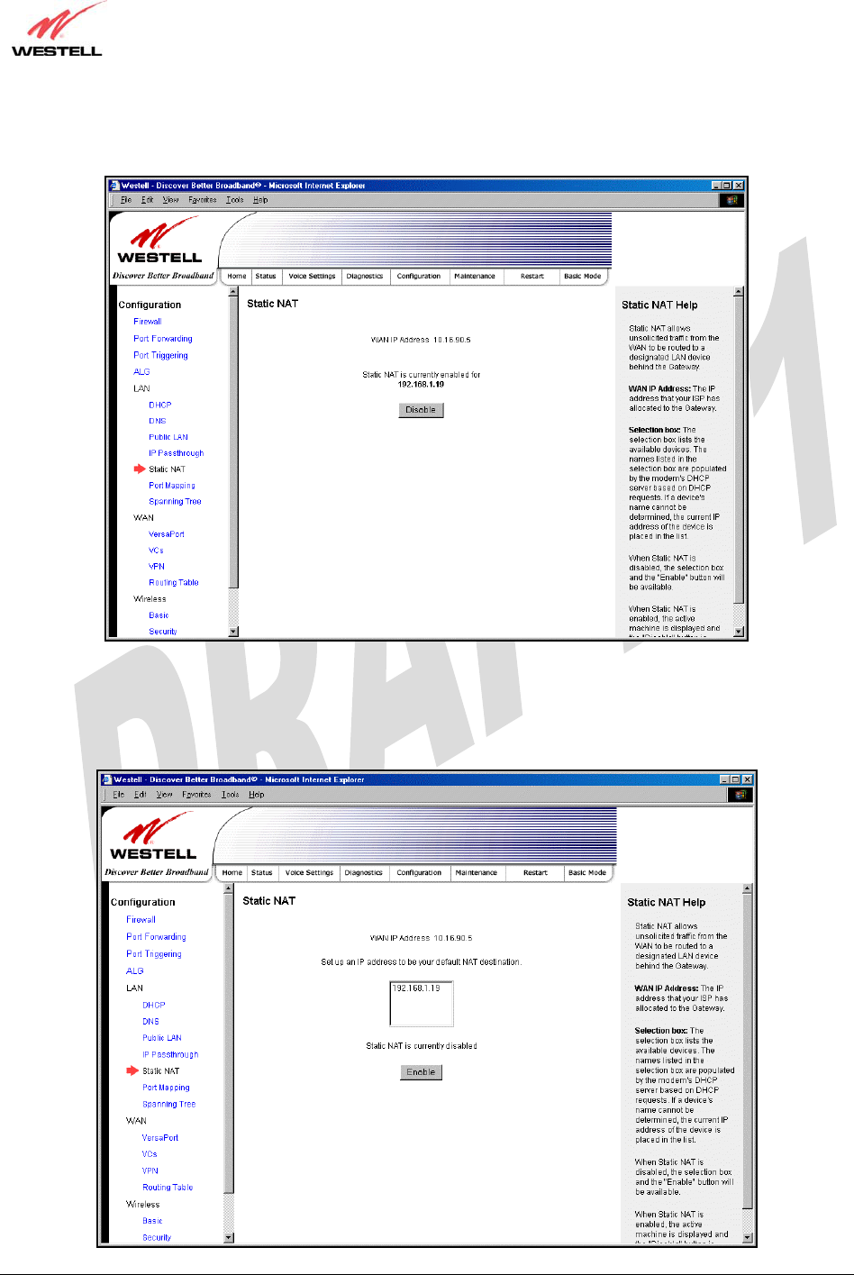
030-300479 Rev. A
Draft 1 – 10/17/05
030-300479 Rev. A 56 October 2005
User Guide UltraLine IIB (Model A90-816030)
If you clicked Enable, the following screen will be displayed, with Static NAT enabled for the IP address or device
name you selected.
15.5.5.2 Disabling Static NAT
To disable Static NAT, click Disable in the Static NAT screen. The following screen will be displayed.
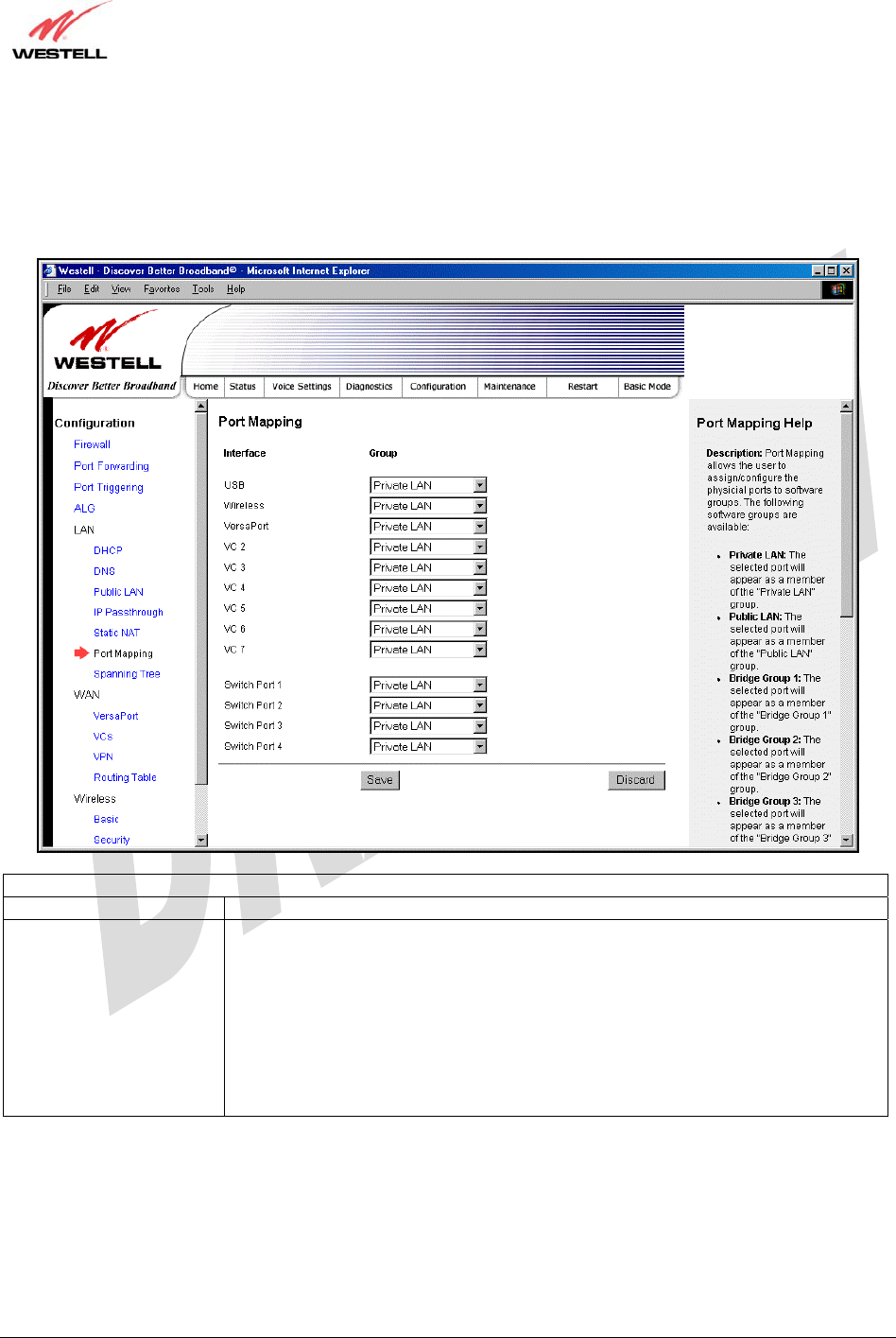
030-300479 Rev. A
Draft 1 – 10/17/05
030-300479 Rev. A 57 October 2005
User Guide UltraLine IIB (Model A90-816030)
15.5.6 Port Mapping
The following screen will be displayed if you select LAN > Port Mapping from the Configuration menu. This
screen enables you to assign the physical ports to software groups. Select the appropriate options from the drop-down
menus, and then click Save to save your settings.
Port Mapping
Interface The physical ports available for mapping.
Group Factory Default: Private LAN
The software defined virtual LAN group to which the port should be assigned:
Possible Responses:
Private LAN
Public LAN
Bridge Group One
Bridge Group Two
Bridge Group Three
Bridge Group Four
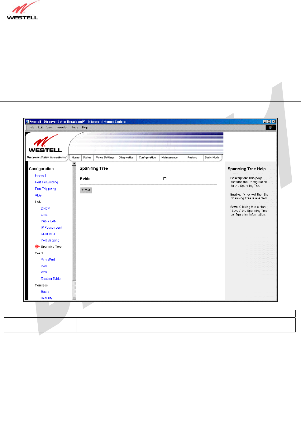
030-300479 Rev. A
Draft 1 – 10/17/05
030-300479 Rev. A 58 October 2005
User Guide UltraLine IIB (Model A90-816030)
15.6 Spanning Tree
The following screen will be displayed if you select LAN > Spanning Tree from the Configuration menu. This
screen enables you to configure Spanning Tree functionality on your modem. To activated Spanning Tree, click the
box adjacent to Enable (a check mark will appear in the box). Next, click Save to save your settings.
Description: Spanning Tree provides path redundancy while preventing undesirable loops in the network.
NOTE: By factory default, Spanning Tree is disabled.
Spanning Tree
Enable When this box is checked Spanning Tree is activated.
If the box is unchecked, Spanning Tree is deactivated.
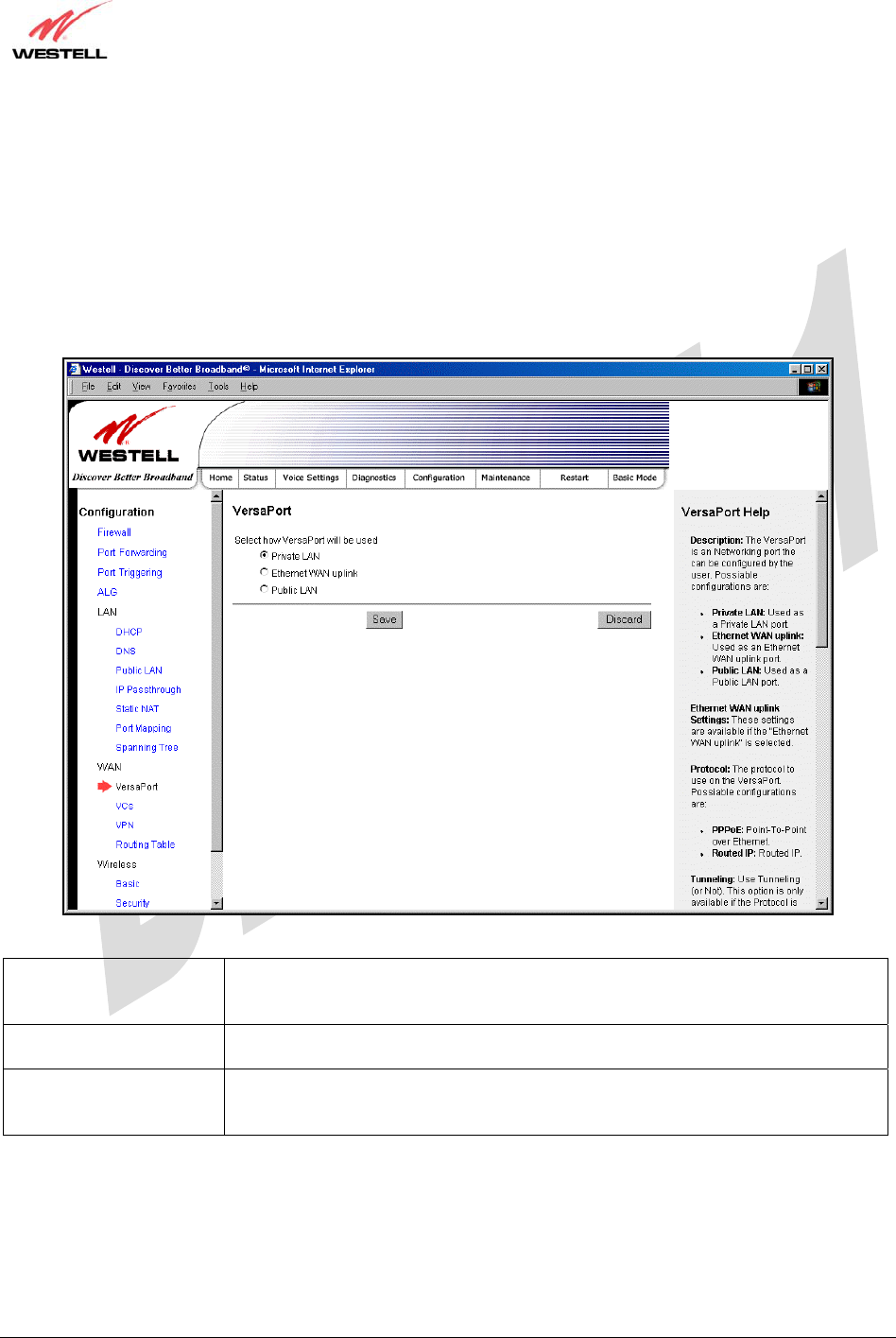
030-300479 Rev. A
Draft 1 – 10/17/05
030-300479 Rev. A 59 October 2005
User Guide UltraLine IIB (Model A90-816030)
15.7 WAN Configuration
15.7.1 VersaPort
The following screen will be displayed if you select WAN > VersaPort from the Configuration menu. This
function will enable you to configure the VersaPort settings for your modem. Click on one of the options (Private
LAN, Ethernet WAN Uplink, or Public LAN) to select how VersaPort will be used. Next, click Save to save your
settings.
Private LAN Factory Default = Private LAN
If selected, the VERSAPORT™2 port will function as a fifth Ethernet LAN port.
When using Private LAN, the router’s DSL transceiver will be Enabled.
Ethernet WAN Uplink If selected, the VERSAPORT™2 port will function as an Ethernet WAN Uplink
port, and the router’s DSL transceiver will be Disabled.
Public LAN If selected, the VERSAPORT™2 port will function as a second segment. When
using Public LAN, the router’s DSL transceiver will be Enabled. Use the Public
LAN Configuration menus to configure the LAN settings.
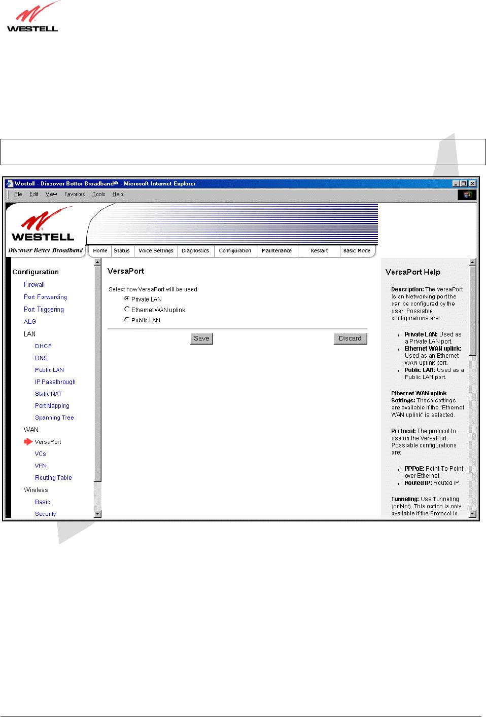
030-300479 Rev. A
Draft 1 – 10/17/05
030-300479 Rev. A 60 October 2005
User Guide UltraLine IIB (Model A90-816030)
15.7.2 Private LAN – Configuring NAT
If you select Private LAN in the VersaPort screen, the following screen will be displayed. Private LAN enables you
to set up a network behind the Gateway. After you have entered the appropriate values, click Save to save your
settings.
NOTE: When your Gateway is configured for Private LAN, the VERSAPORT™2 port functions as fifth Ethernet
LAN port. Private LAN is the factory default configuration for the VersaPort screen.
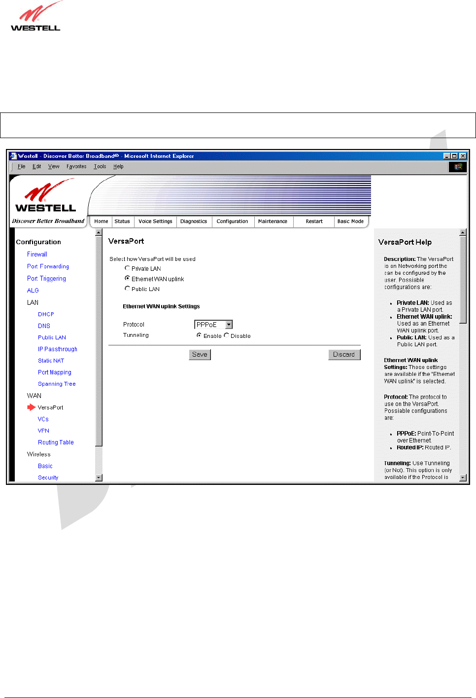
030-300479 Rev. A
Draft 1 – 10/17/05
030-300479 Rev. A 61 October 2005
User Guide UltraLine IIB (Model A90-816030)
15.7.3 Ethernet WAN Uplink
If you select Ethernet WAN Uplink in the VersaPort Configuration screen, the following screen will be displayed.
NOTE: Selecting Ethernet WAN Uplink will allow the Gateway’s WAN interface to use the VERSAPORT™2
port. This will disable the Gateway’s DSL transceiver.
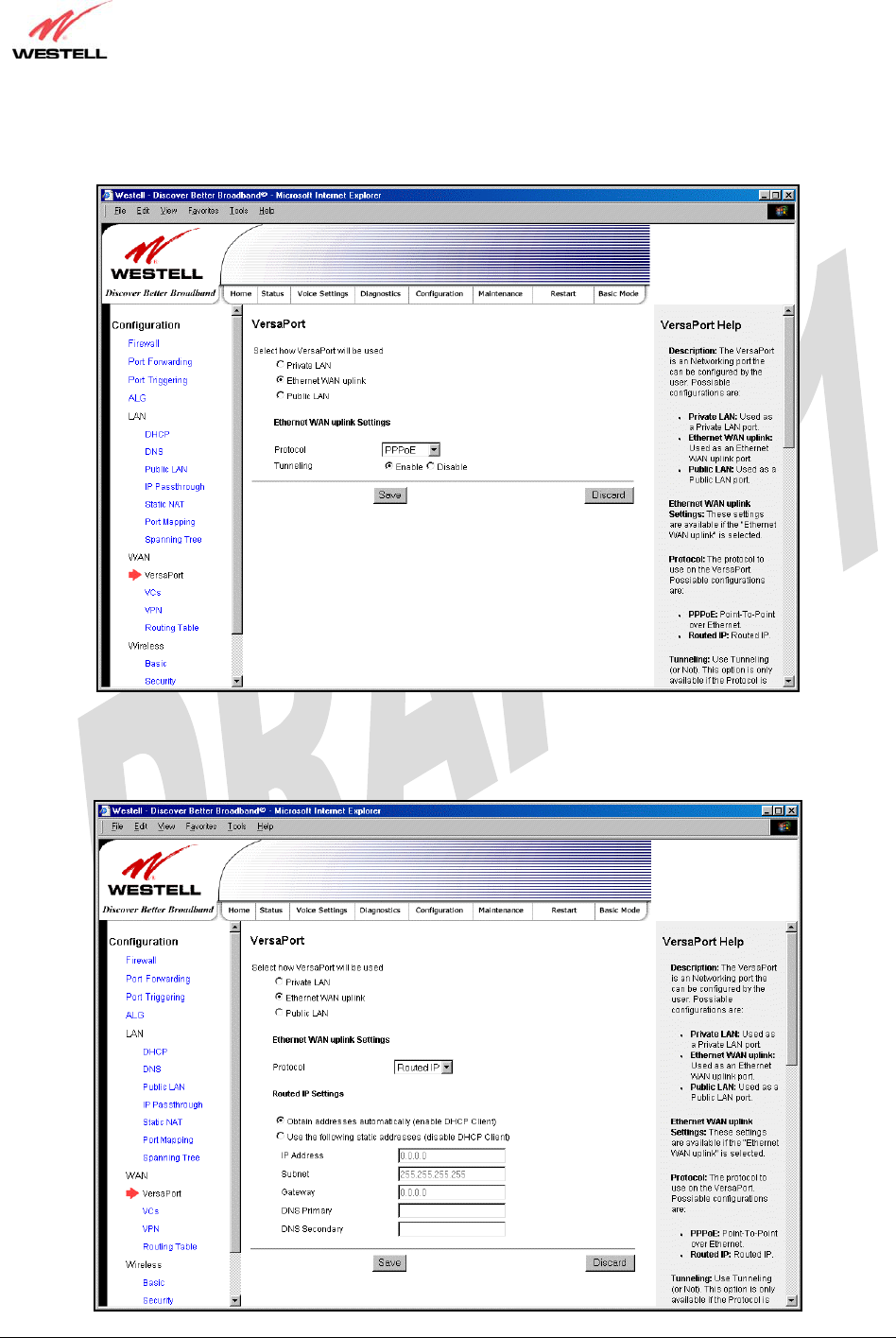
030-300479 Rev. A
Draft 1 – 10/17/05
030-300479 Rev. A 62 October 2005
User Guide UltraLine IIB (Model A90-816030)
If you select PPPoE as the protocol for your Ethernet WAN Uplink setting, the following screen will be displayed.
Click Save to save your settings.
If you select Routed IP as the protocol for your Ethernet WAN Uplink setting, the following screen will be
displayed. Enter the appropriate values in the fields provided, and then click Save to save your settings.
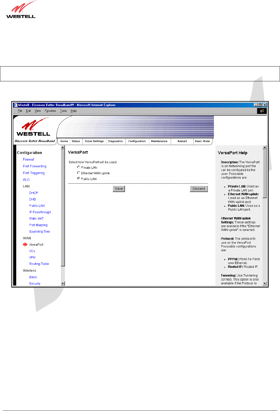
030-300479 Rev. A
Draft 1 – 10/17/05
030-300479 Rev. A 63 October 2005
User Guide UltraLine IIB (Model A90-816030)
15.7.4 Public LAN – Multiple IP Address Passthrough
If you select Public LAN in the VersaPort Configuration screen, the following screen will be displayed.
NOTE: Selecting Public LAN will enable the VersaPort will function as a second Ethernet LAN port. When
VersaPort is configured for Public LAN, the Gateway’s DSL transceiver will be enabled.
Use the Public LAN configuration menu to configure the LAN settings.
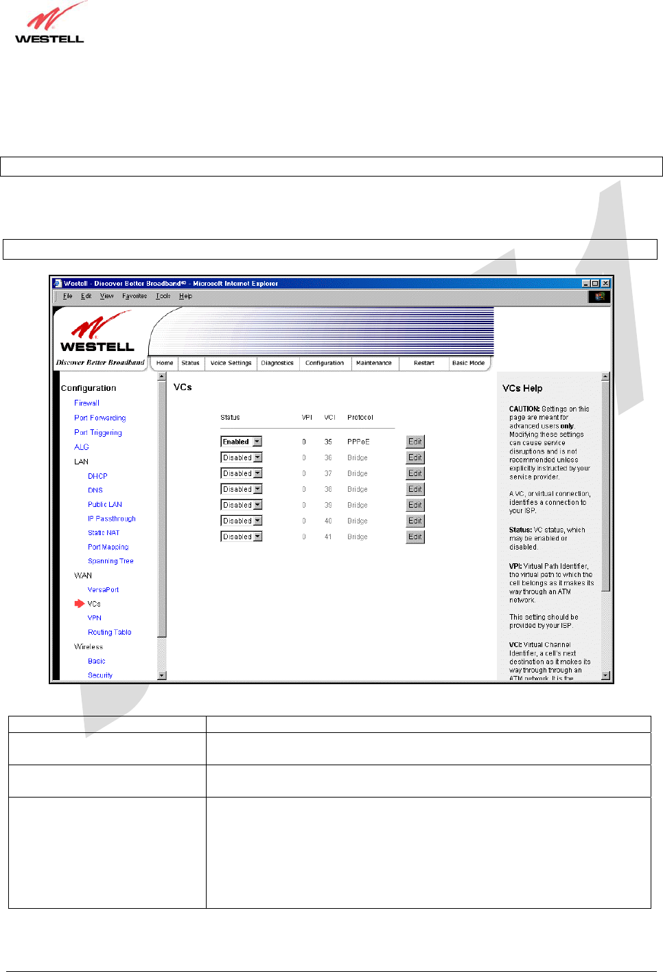
030-300479 Rev. A
Draft 1 – 10/17/05
030-300479 Rev. A 64 October 2005
User Guide UltraLine IIB (Model A90-816030)
15.7.5 VCs
The following screen will be displayed if you select WAN > VCs from the Configuration screen.
NOTE: The VCs cannot be modified if the VersaPort™2 port is configured as the WAN port.
The Edit button enables you to change the VC configuration settings of the Gateway. Details on the edit button are
explained later in this section.
NOTE: The actual information displayed in this screen may vary, depending on the network connection established.
Status Allows you to enable or disable your VC (Virtual Connection)
VPI Displays the VPI (Virtual Path Indicator) value for a particular VC, which is
defined by your Service Provider.
VCI Displays the VCI (Virtual Channel Indicator) value for a particular VC,
which is defined by your Service Provider.
Protocol
NOTE: The configuration
specified by your Service
Provider will determine which
Protocols are available to you.
Displays the Protocol for each VC, which is specified by your Service
Provider.
Possible Response:
PPPoA = Point to Point Protocol over ATM (Asynchronous Transfer Mode)
PPPoE = Point to Point Protocol over Ethernet
Bridge = Bridge Protocol
Routed IP = IP over ATM
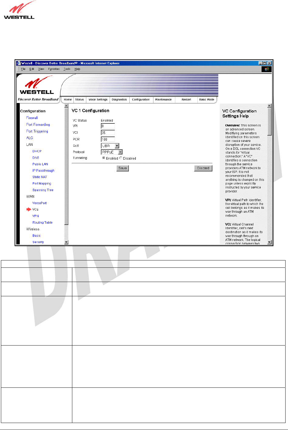
030-300479 Rev. A
Draft 1 – 10/17/05
030-300479 Rev. A 65 October 2005
User Guide UltraLine IIB (Model A90-816030)
If you click edit in the VCs Configuration screen, the following screen will be displayed. Enter the appropriate
values, and then click Save to save your settings.
VC 1 Configuration
VPI This setting allows you to change your VPI (Virtual Path Indicator) value for a
particular VC, which is defined by your Service Provider.
VCI This setting allows you to change your VCI (Virtual Channel Indicator) value for a
particular VC, which is defined by your Service Provider.
PCR Factory Default = 100%
Peak Cell Rate (PCR)-The maximum rate at which cells can be transmitted across a
virtual circuit, specified in cells per second and defined by the interval between the
transmission of the last bit of one cell and the first bit of the next.
This value is a percentage of the current data rate.
100 allows this VC to use 100% of the available bandwidth.
80 allows this VC to use 80% of the available bandwidth.
QoS Select the Quality of Service, which is determined by your Service Provider.
Possible Responses:
UBR = Unspecified Bit Rate
CBR = Constant Bit Rate
rt-VBR = real-time Variable Bit Rate
nrt-VBR = non-real-time Variable Bit Rate
Protocol The Protocol for each VC, which is specified by your Service Provider.
Possible Responses:
PPPoA = Point to Point Protocol over ATM (Asynchronous Transfer Mode)
PPPoE = Point to Point Protocol over Ethernet
Bridge = Bridge Protocol
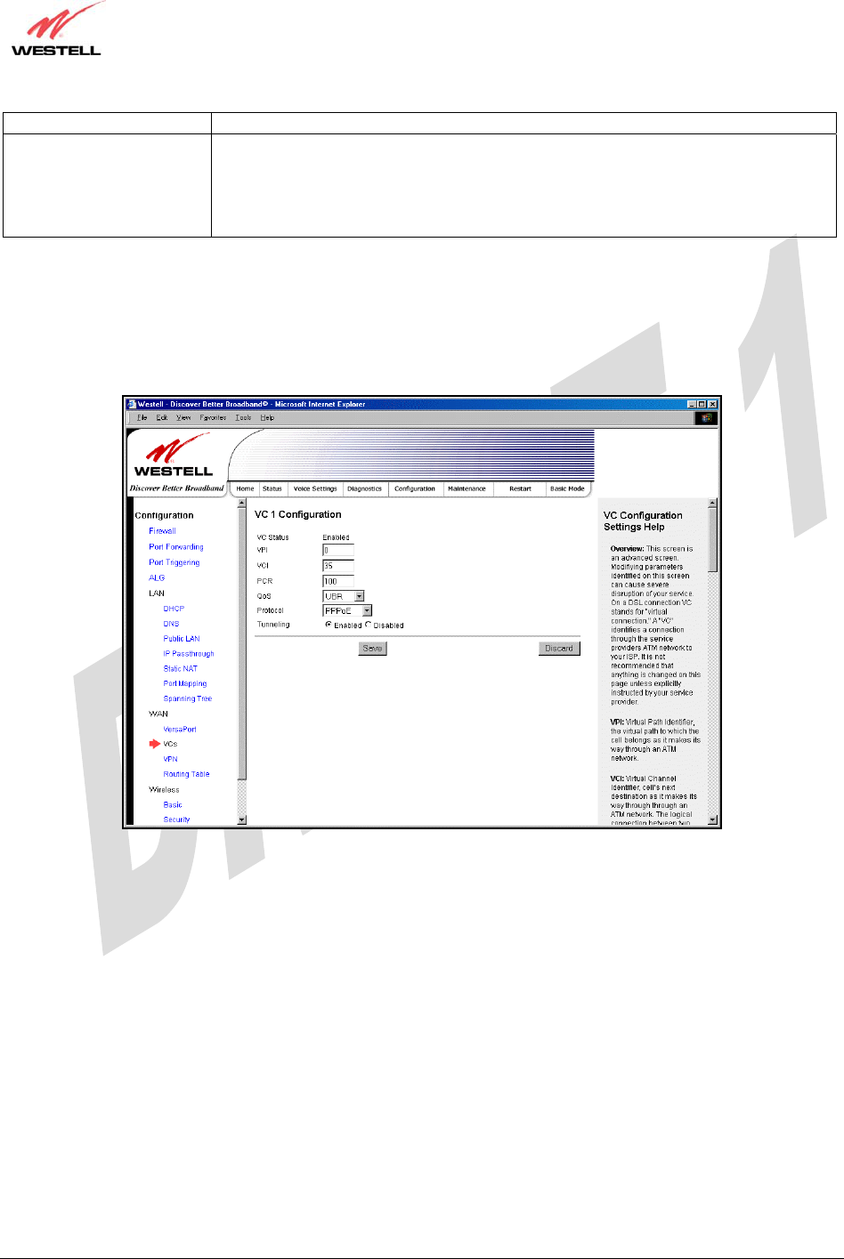
030-300479 Rev. A
Draft 1 – 10/17/05
030-300479 Rev. A 66 October 2005
User Guide UltraLine IIB (Model A90-816030)
Routed IP = IP over ATM
Tunneling Factory Default = Enable
If Enabled, this option enables PPP traffic from the LAN to be bridged to the WAN.
This feature enables you to use a PPPoE shim on the host computer to connect to the
Internet service provider, by bypassing the Gateway’s capability to do this.
Note: Tunneling is available in PPPoE mode only.
15.7.5.1 Configuring WAN VC Protocol for PPPoE mode
To configure the WAN VC Protocol for PPPoE mode, select PPPoE from the Protocol drop-down menu, the
following screen will be displayed. Enter the appropriate values, and then click Save to save your settings.
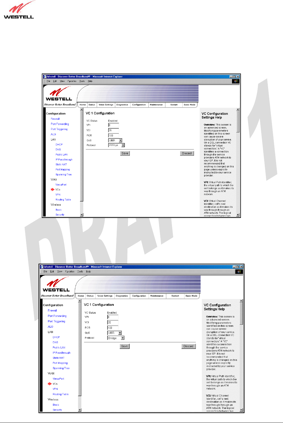
030-300479 Rev. A
Draft 1 – 10/17/05
030-300479 Rev. A 67 October 2005
User Guide UltraLine IIB (Model A90-816030)
15.7.5.2 Configuring WAN VC Protocol for PPPoA mode
To configure the WAN VC Protocol for PPPoA mode, select PPPoA from the Protocol drop-down menu, the
following screen will be displayed. Enter the appropriate values, and then click Save to save your settings.
15.7.5.3 Configuring WAN VC Protocol for Bridge mode - (MAC Bridge)
To configure the WAN VC Protocol for Bridge mode, select Bridge from the Protocol drop-down menu, the
following screen will be displayed. Enter the appropriate values, and then click Save to save your settings.
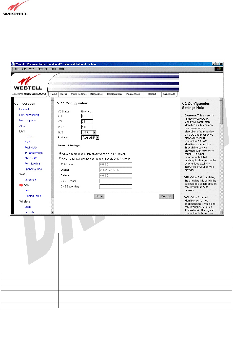
030-300479 Rev. A
Draft 1 – 10/17/05
030-300479 Rev. A 68 October 2005
User Guide UltraLine IIB (Model A90-816030)
15.7.5.4 Configuring WAN VC Protocol for Routed IP mode
If you select Routed IP from the Protocol drop-down menu, the following screen will be displayed. Enter the
appropriate values, and then click Save to save your settings.
VC 1 Routed IP Settings
DHCP Client Factory Default = Enable
If enabled the router will obtain its IP address, gateway address and DNS server
address automatically from the network. If disabled you must manually enter the
information.
Possible Response:
Select Enable to activate the DHCP client.
Select Disable to deactivate the DHCP client.
IP Address Displays the Gateway’s IP network address.
Subnet Displays the Gateway’s subnet mask settings.
Gateway Displays the Gateway’s IP gateway address
DNS Primary Displays the IP address of primary Domain Name Service (DNS) server your router
is using.
DNS Secondary Displays the IP address of secondary DNS server your router is using.
15.7.6 VPN
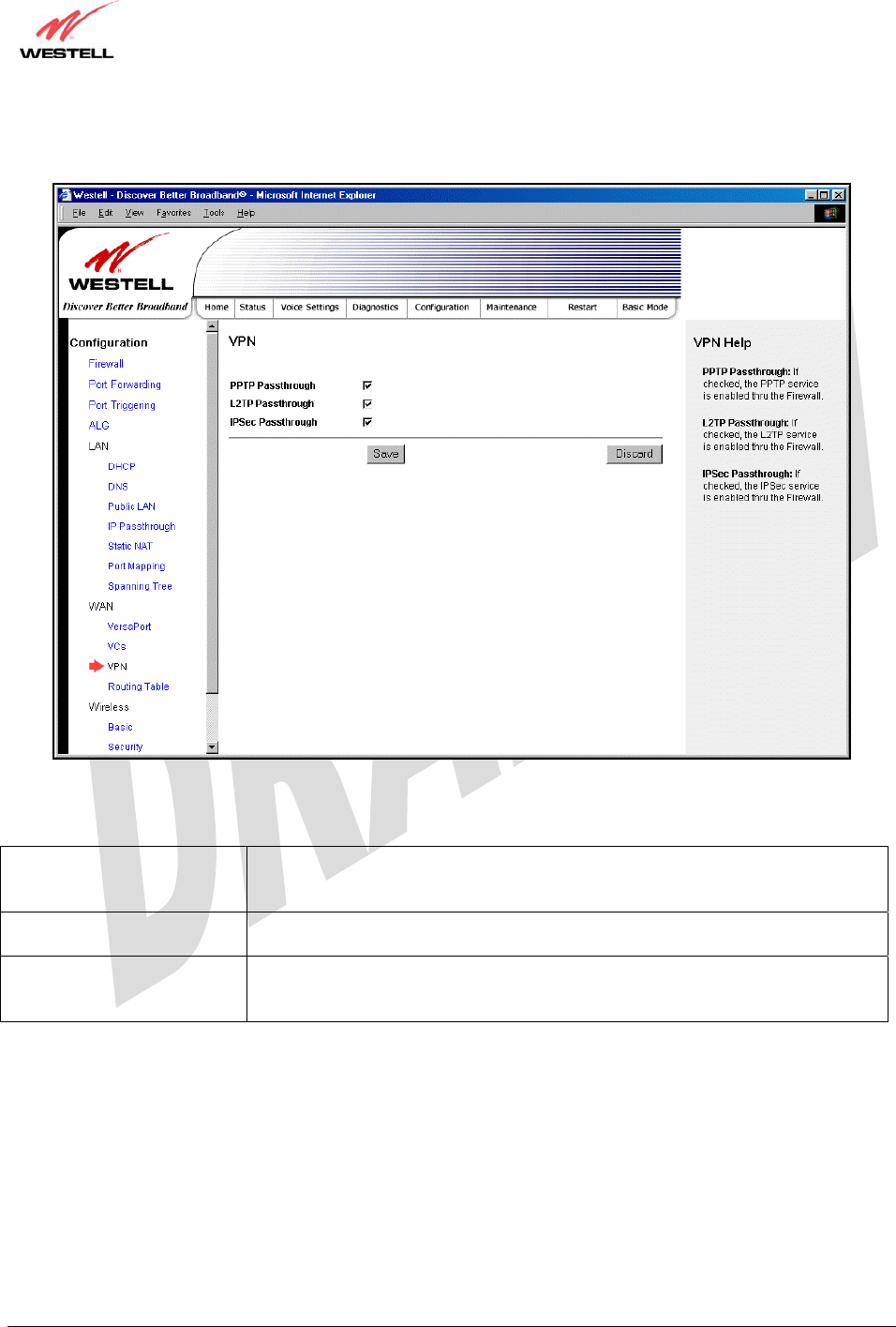
030-300479 Rev. A
Draft 1 – 10/17/05
030-300479 Rev. A 69 October 2005
User Guide UltraLine IIB (Model A90-816030)
The following settings will be displayed if you select WAN > VPN from the Configuration menu. Enter the
appropriate values, and then click Save to save your settings.
PPTP Passthrough Factory Default = Enabled
If enabled (a check mark will appear in the box), PPTP will work through the
Gateway’s NAT function.
L2TP Passthrough Factory Default = Enabled
If enabled, IPSec using ESP and L2TP can be supported via an ALG.
IPSec Passthrough Factory Default = Enabled
If enabled, IPSec using ESP can be supported via an ALG. IPSec using AH cannot
be supported through NAT.
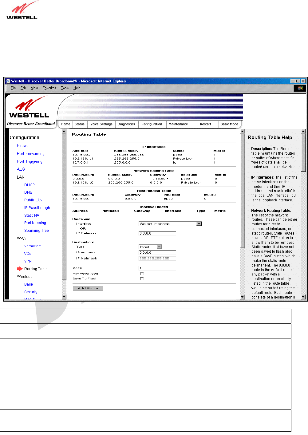
030-300479 Rev. A
Draft 1 – 10/17/05
030-300479 Rev. A 70 October 2005
User Guide UltraLine IIB (Model A90-816030)
15.7.7 Routing Table
The following settings will be displayed if you select WAN > Routing Table from the Configuration menu. To add
a route to the Network Routing Table, enter the appropriate values, and then click Add Route.
IP Interfaces
The list of active interfaces on the modem, their IP addresses and subnet masks.
Address The IP interface address of the interface.
Subnet Mask The subnet mask of the interface.
Name The name assigned to the interface.
Possible names are:
ppp0 – The WAN interface when the router is in PPPoE or PPPoA mode.
DSLVC1 – The WAN interface when the router is in DSL Routed IP mode.
VersaPort – The WAN interface when the router is in uplink Routed IP mode.
Private LAN – The main Ethernet interface.
Public LAN – The second Ethernet interface.
l0 – The local loopback interface.
Metric The numeric value assigned to this interface used to calculate the best route to a
destination address.
Networking Routing Table
The list of the network routes. These can be either routes for directly connected networks, or static routes that have
been entered.

030-300479 Rev. A
Draft 1 – 10/17/05
030-300479 Rev. A 71 October 2005
User Guide UltraLine IIB (Model A90-816030)
Destination The IP subnet of the destination network.
Subnet Mask The subnet mask of the destination network.
Gateway The IP address of the default gateway for this route.
Interface Indicates the name of the router’s interface to use for this route.
Metric The numeric value assigned to this route, used to calculate the best route to a
destination network.
Host Routing Table
The list of host routes. A host route is an IP route with a 32-bit mask.
Destination The IP address of the destination host.
Gateway The IP address of the default gateway for this route.
Interface Indicates the name of the router’s interface to use for this route.
Metric The numeric value assigned to this route, used to calculate the best route to a
destination network.
Inactive Routes
The list of routes whose interface is currently not in service.
Address The IP address of the destination network.
Netmask The subnet mask of the destination network.
Gateway The IP address of the default gateway for this route.
Interface The name of the router’s interface associated with this route.
Type Indicates if this route is a network route, a host route, or a default route.
Metric The numeric value assigned to this route used to calculate the best route to a
destination network.
The following sections allow you to add static routes to the gateway’s routing table.
Route Via
Allows you to specify either the interface or the default gateway that the router should use for this static route. If an
interface is not specified, the correct interface will be automatically chosen, based on the gateway addresses.
Interface Select the interface that will be used for this static route. If you enter an interface, you
cannot specify a default gateway.
IP Gateway Enter the IP address of the default gateway used for this static route. The specified
gateway must be reachable; this means that the modem must have a route to the
gateway. You must specify either an interface or a gateway for each static route.
Destination
Allows you to specify the destination network or host.
Type Factory Default = Host
Possible Response:
Host – The static route maps to a single IP host.
Network – The static route maps to a network.
Default – The static route maps to a default route.
IP Address The IP subnet of the destination network or host.
IP Netmask The subnet mask of the destination network. If the route type was a host, a 32-bit
subnet mask will be automatically populated.
Metric The numeric value assigned to this route, used to calculate the best route to a
destination network.
RIP Advertised This determines whether or not to advertise the static route using RIP. (RIP must also
be enabled before the route will be advertised.)
If Enabled (box is checked), RIP Advertised will be activated.
If Disabled, RIP Advertised will not be activated.
Save to Flash If Enabled (box is checked), the route will be made permanent by saving it to flash
memory.
If Disabled, the route will disappear the next time the modem restarts.
Add Route This button enables you to add a new static route in the modem. Note: When adding a
route, you may need to reload the page for the route to appear in the “active” Routes.
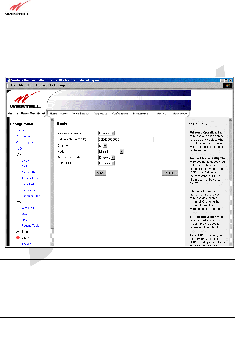
030-300479 Rev. A
Draft 1 – 10/17/05
030-300479 Rev. A 72 October 2005
User Guide UltraLine IIB (Model A90-816030)
15.8 Wireless Configuration
15.8.1 Basic
The following settings will be displayed if you select Wireless > Basic from the Configuration menu. Enter the
appropriate values, and then click Save to save your settings.
Wireless Basic Configuration
Wireless Operation Factory Default = Enabled
When disabled, no wireless stations will be able to connect to the Gateway.
Network Name (SSID) This string (32 characters or less) is the name associated with the AP. To connect to the
AP, the SSID on a Station card must match the SSID on the AP card or be set to “ANY.”
Channel Factory Default = 6
The AP transmits and receives data on this channel. The number of channels to choose
from is pre-programmed into the AP card. Station cards do not have to be set to the same
channel as the AP; the Stations scan all channels and look for an AP to connect to.
Possible Response:
1 through 11
Mode Factory Default = Mixed
This setting allows station to communicate with the Gateway.
Possible Response:
Mixed: Station using any of the 802.11b, 802.11b+, and 802.11g rates can communicate
with the Gateway.
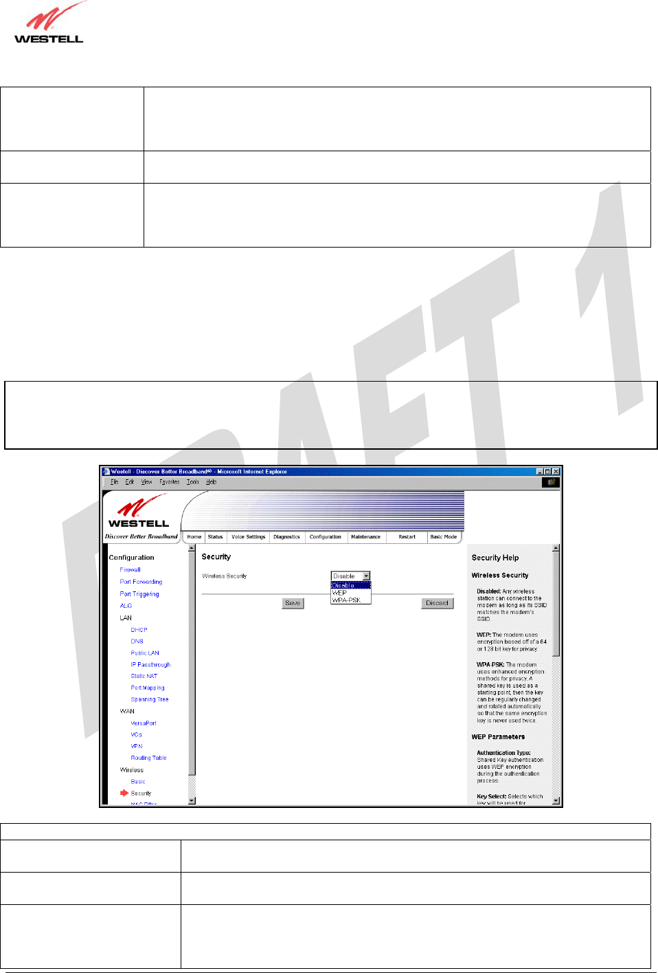
030-300479 Rev. A
Draft 1 – 10/17/05
030-300479 Rev. A 73 October 2005
User Guide UltraLine IIB (Model A90-816030)
Legacy Mixed: Same as Mixed, but also allows older 802.11b cards to communicate
with the Gateway.
11b only: Communication with the Gateway is limited to 802.11b
11g only: Communication with the Gateway is limited to 802.11g
Frameburst Mode Factory Default = Disable
If enabled, additional algorithms are used for increased throughput.
Hide SSID Factory Default = Disable
If enabled, the Gateway will not broadcast the SSID. To connect to the Gateway, each
Station must configure its SSIDs so that it matches the Gateway’s Network Name
(SSID).
15.8.2 Wireless Security
The following screen will be displayed if you select Wireless > Security from the Configuration menu. Select the
desired security option from the Wireless Security drop-down menu. After you configured your wireless security
settings, click Save to save the settings.
IMPORTANT: Client PCs can use any Wireless Fidelity (Wi-Fi) 802.11b/g/g+ certified card to communicate with
the Gateway. The Wireless card and Gateway must use the same security code type. If you use WPA-PSK or WEP
wireless security, you must configure your computer’s wireless adapter for the security code that you use. You
can access the settings in the advanced properties of the wireless network adapter.
Wireless Security
Disable Factory Default = Disable
If Disable is selected, wireless security will not be activated on your Gateway.
WEP Selecting WEP enables you set up Wired Equivalent Privacy (WEP) on your
Gateway. WEP uses encryption based on a 64- or 128-bit key for privacy.
WPA-PSK Selecting WPA-PSK enables you set up Wi-Fi Protected Access-Pre-Shared Key
on your Gateway. WPA-PSK uses enhanced encryption methods for privacy. A
shared key is used as a starting point, and then the key can be regularly changed
and rotated automatically so that the same encryption key is never used twice.
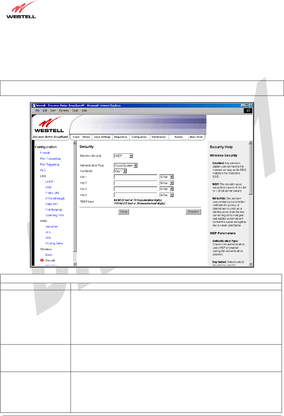
030-300479 Rev. A
Draft 1 – 10/17/05
030-300479 Rev. A 74 October 2005
User Guide UltraLine IIB (Model A90-816030)
15.8.2.1 Enabling WEP Security
If you select WEP from the Wireless Security drop-down menu, the following screen will be displayed. Enter the
appropriate values, and then click Save to save the settings.
NOTE: The WEP key must be 64 bit (5 text characters or 10 hexadecimal digits in length) or 128 bit (13 text
characters or 26 hexadecimal digits in length).
Wireless Security (WEP)
Wireless Security WEP has been selected.
Authentication Type Factory Default = Open System
Possible Response:
Open System: Open System authentication allows any station to associate with the
wireless network but only stations with the valid WEP key can send or receive data
from the router. Open System authentication is considered to be more secure than
Shared Key authentication.
Shared Key: Shared Key authentication requires the station to authenticate with the
router using the WEP key before it can associate with the wireless network.
Key Select Factory Default = Key 1
Selects which WEP key the router should use.
Note: The WEP key must be the same value and type for both the Gateway and the
wireless network adapter.
Key 1
To
Key 4
Select the length of the WEP key from the pull down menu and enter key WEP Key in
the box. A 64-bit key must be either 5 text characters or 10 hexadecimal characters. A
128-bit key must be 13 text characters or 26 hexadecimal characters. The only
allowable hexadecimal characters are 0-9 and A-F.
Note: The WEP key must be the same value and type for both the Gateway and the
wireless network adapter.
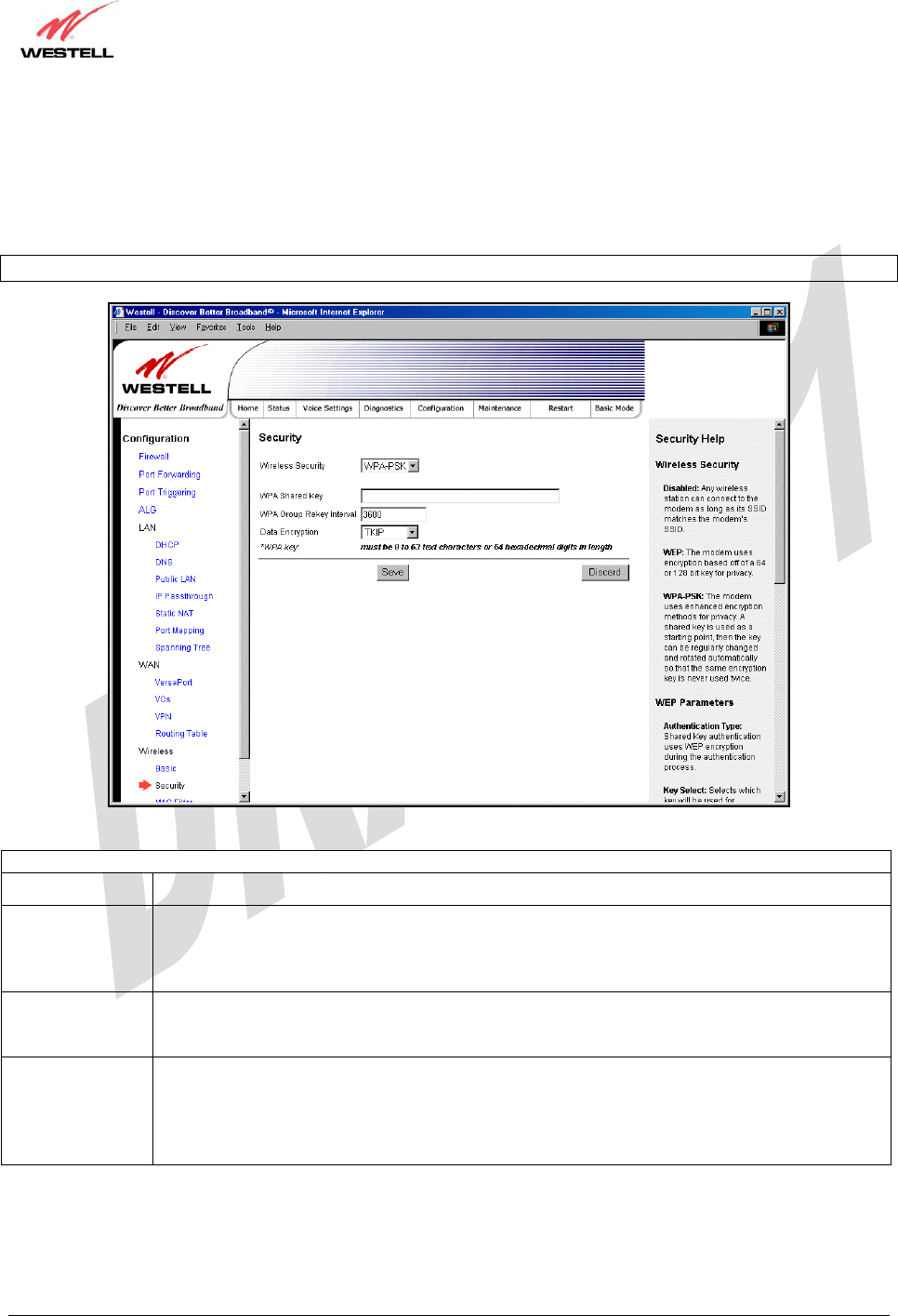
030-300479 Rev. A
Draft 1 – 10/17/05
030-300479 Rev. A 75 October 2005
User Guide UltraLine IIB (Model A90-816030)
15.8.2.2 Enabling WPA-PSK Security
If you select WPA-PSK from the Wireless Security drop-down menu, the following screen will be displayed. Enter
the appropriate values, and then click Save to save the settings.
NOTE: The WPA key must be 8 to 63 characters or 64 hexadecimal digits in length.
Wireless Security (WPA-PSK)
Wireless Security WPA-PSK has been selected.
WPA Shared
Key This is a passphrase (also called a shared secret) that must be entered in both the wireless router
and the wireless client. This shared secret can be between 8 to 63 text characters and can
include special characters and spaces. The more random your WPA Shared Key, the more
secure it is.
WPA Group
Rekey Interval Factory Default = 3600
The number of seconds between rekeying the WPA group key. Zero “0” means that rekeying is
disabled.
Data Encryption Factory Default = TKIP
Possible Response:
TKIP- Selecting this option enables the Temporal Key Integrity Protocol for data encryption.
AES- Selecting this option enables the Advanced Encryption Standard for data encryption.
TKIP/AES- Selecting this option enables the Gateway to accept either TKIP or AES encryption
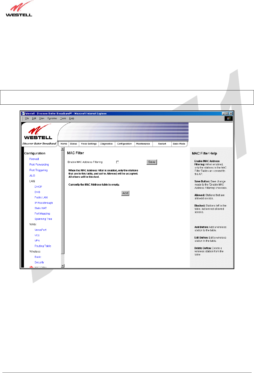
030-300479 Rev. A
Draft 1 – 10/17/05
030-300479 Rev. A 76 October 2005
User Guide UltraLine IIB (Model A90-816030)
15.8.3 MAC Filter
The following settings will be displayed if you select Wireless > MAC Filter from the Configuration menu. This
screen enables you to configure the MAC filter settings for your Gateway.
After you have finished adding, editing or deleting MAC addresses from the MAC Filter table (as explained in the
following paragraphs), click the box adjacent to Enable MAC Address Filtering (a check mark will appear in the
box), and then click Save to save your settings.
NOTE: When the MAC address Filter is enabled (box is checked), only the stations that are in the MAC Filter table
and that are set to Allowed will be accepted by the Gateway. All other stations will be blocked.
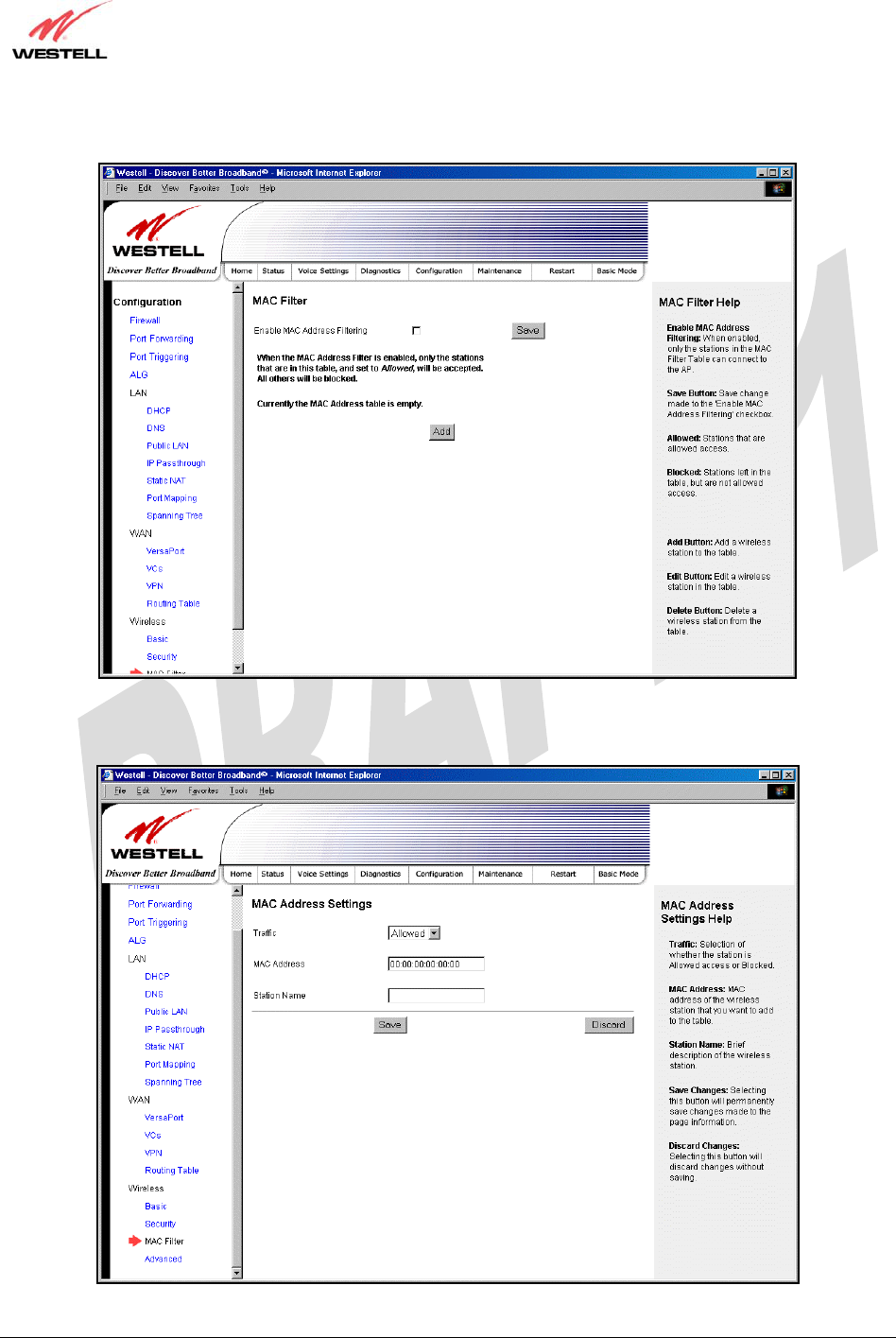
030-300479 Rev. A
Draft 1 – 10/17/05
030-300479 Rev. A 77 October 2005
User Guide UltraLine IIB (Model A90-816030)
To add stations to the MAC Address table, click the add button.
If you clicked add, the following screen will be displayed. Enter the appropriate values in the fields provided, and
then click Save to save your settings.
030-300479 Rev. A
Draft 1 – 10/17/05
030-300479 Rev. A 78 October 2005
User Guide UltraLine IIB (Model A90-816030)
MAC Address Settings
Traffic Factory Default = Allowed
If Blocked is selected, the station will be blocked (it cannot access the Gateway).
MAC Address Factory Default = 00:00:00:00:00:00
The MAC address of the wireless station you want to add.
Station Name The name of the wireless station you want to add.
If you clicked Save, the following pop-up screen will be displayed. Click OK to continue.
NOTE: Wireless access will be interrupted and the wireless stations may require reconfiguration.
If you clicked OK, in the preceding pop-up screen, the following screen will be displayed. The screen displays the list
of MAC addresses added to the MAC Address Filter Table. You may now add, edit, or delete MAC addresses from
the table by clicking on the desired MAC address (displayed in the window) and then by clicking either Add, Edit, or
Delete. Next, click OK in the pop-up screen.
After you have finished adding, editing or deleting MAC addresses in the MAC Filter table, click the box adjacent to
Enable MAC Address Filtering (a check mark will appear in the box). Click Save to save your settings.
NOTE: When the MAC address Filter is enabled (box is checked), only the stations that are in MAC Filter table and
that are set to Allowed will be accepted by the Gateway. All other stations will be blocked.
030-300479 Rev. A
Draft 1 – 10/17/05
030-300479 Rev. A 79 October 2005
User Guide UltraLine IIB (Model A90-816030)
15.8.4 Advanced Wireless Settings
The following settings will be displayed if you select Wireless > Advanced from the Configuration menu. Enter the
appropriate values, and then click Save to save the settings.
Wireless Advanced Configuration
Beacon Period The time interval between beacon frame transmissions. Beacons contain rate and
capability information. Beacons received by stations can be used to identify the access
points in the area.
RTS Threshold RTS/CTS handshaking will be performed for any data or management MPDU
containing a number of bytes greater than the threshold. If this value is larger than the
MSDU size (typically set by the fragmentation threshold), no handshaking will be
performed. A value of zero will enable handshaking for all MPDUs.
Fragmented Threshold Any MSDU or MPDU larger than this value will be fragmented into an MPDU of the
specified size.
DTIM Interval The number of Beacon intervals between DTIM transmissions. Multicast and broadcast
frames are delivered after every DTIM.
Supported Rates
802.11b Rates (Mbps)
802.11g Rates (Mbps)
These are the allowable communication rates that the Gateway will attempt to use. The
rates are also broadcast within the connection protocol as the rates supported by the
Gateway.
If you clicked Save, the following pop-up screen will be displayed. Click OK to continue.
030-300479 Rev. A
Draft 1 – 10/17/05
030-300479 Rev. A 80 October 2005
User Guide UltraLine IIB (Model A90-816030)
16. MAINTENANCE
16.1 Login Administration
The following screen will be displayed if you select Login Administration from the Maintenance menu. Enter the
appropriate values, and then click Save to save the settings.
NOTE: Password must be at least 6 characters and must not exceed 12 characters long. Alphanumeric values are
permitted. The Password and Confirm Password fields are masked with “*” for security measures.
Login Administration
Username The administrator’s username. This is a free-format character string between 5 and 12
characters long, no spaces.
Password The administrator’s password. This is a free-format character string between 6 and 12
characters long, no spaces.
Confirm Password The identical value that was entered in the password field.
030-300479 Rev. A
Draft 1 – 10/17/05
030-300479 Rev. A 81 October 2005
User Guide UltraLine IIB (Model A90-816030)
16.2 Event Log
The following screen will be displayed if you select Event Log from the Maintenance menu. The Remote Logging
function enables event logs to be sent to a machine running a syslog server. To enable Remote Logging, click the box
adjacent to Enable (a check mark will appear in the box) and then enter an IP address in the Remote IP Address
field. Click Save to save your settings.
Event Log
User ID The name of your connection.
DSL State The state of the DSL connection.
Connection Mode The mode of connection used to connect to your ISP.
Connection State The state of the PPP connection.
Ethernet WAN The state of the Ethernet WAN connection.
Remote Logging
Enable Enables remote logging of Event Logs
Remote IP Address The IP address of the syslog server machine on the local area network to which the
Event Logs are sent.
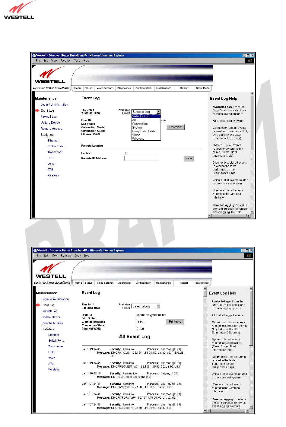
030-300479 Rev. A
Draft 1 – 10/17/05
030-300479 Rev. A 82 October 2005
User Guide UltraLine IIB (Model A90-816030)
To view logged events, select an option from the Available LOGS drop-down menu.
If you select All, the following screen will be displayed. To obtain a printable version of the Event logs, click on
Printable.
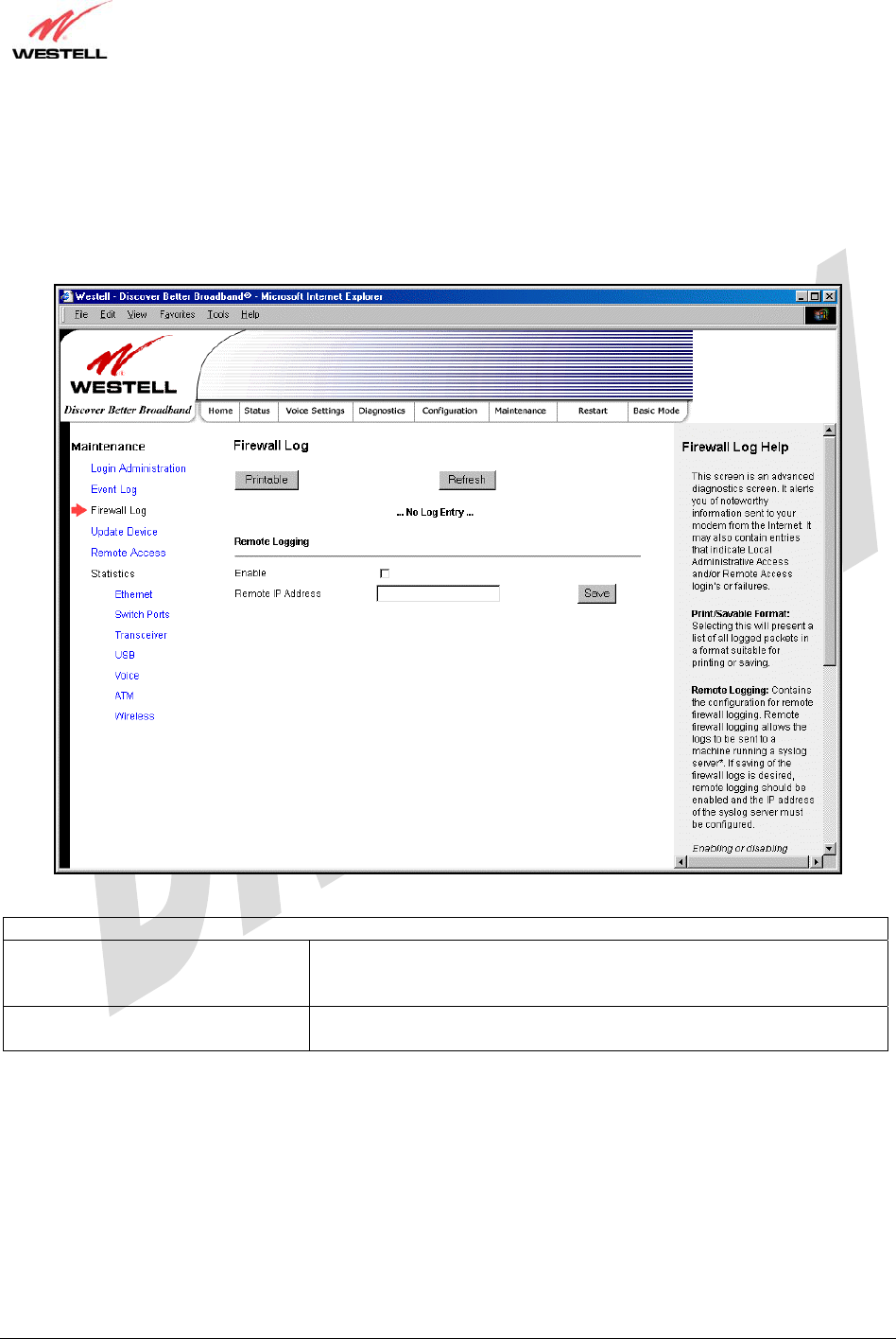
030-300479 Rev. A
Draft 1 – 10/17/05
030-300479 Rev. A 83 October 2005
User Guide UltraLine IIB (Model A90-816030)
16.3 Firewall Log
The following screen will be displayed if you select Firewall Log from the Maintenance menu. To obtain a
printable version of the firewall logs, click on Printable. Click on Refresh to refresh the screen. To enable Remote
Logging, click the box adjacent to Enable (a check mark will appear in the box) and then enter an IP address in the
Remote IP Address field. Click Save to save your settings.
Remote Logging
Enable Factory Default = Disable
If enabled (a check mark will appear in the box), the Gateway will send
firewall logs to a syslog server.
Remote IP Address The IP address of the syslog server machine to which the diagnostics logs
to be sent.
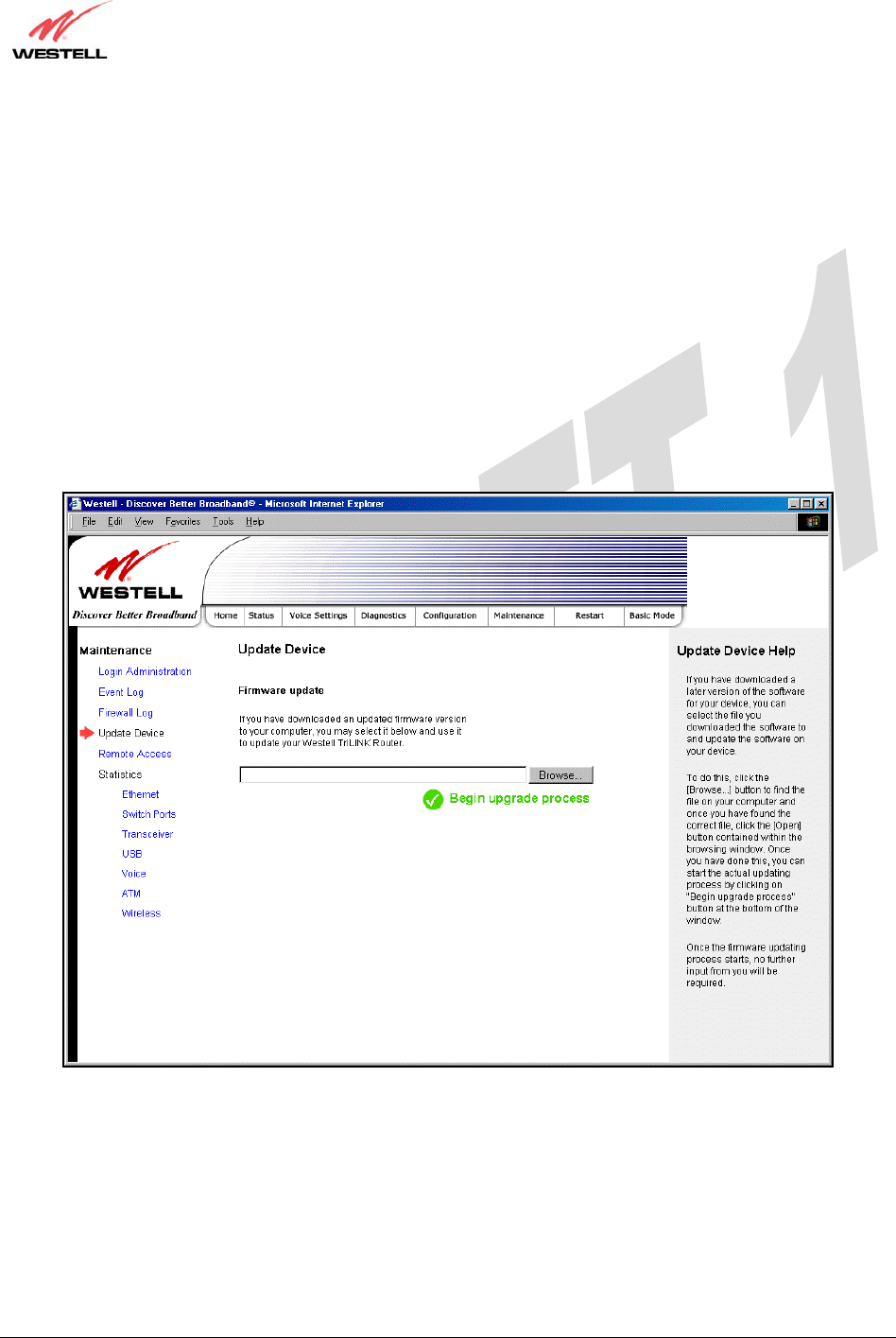
030-300479 Rev. A
Draft 1 – 10/17/05
030-300479 Rev. A 84 October 2005
User Guide UltraLine IIB (Model A90-816030)
16.4 Update Device
The following screen will be displayed if you select Update Device from the Maintenance menu. This screen
enables you to identify the version of software in your device. You can also update the software in your device to the
latest version supported.
To update your modem to the latest software version supported, perform the following steps:
1. Download the update file and store it to a location on your PC.
2. Click the Browse button in the Update Modem screen to navigate to the update file on your PC.
3. Click on the update file and then click Open. The path to the update file will appear in the Browse bar.
4. Click Begin upgrade process to begin the software update for your modem.
5. After your modem has been updated, wait a brief moment for the modem to reset and establish a DSL sync.
6. Confirm that the DSL LED on your modem is solid green before continuing your modem’s configuration.
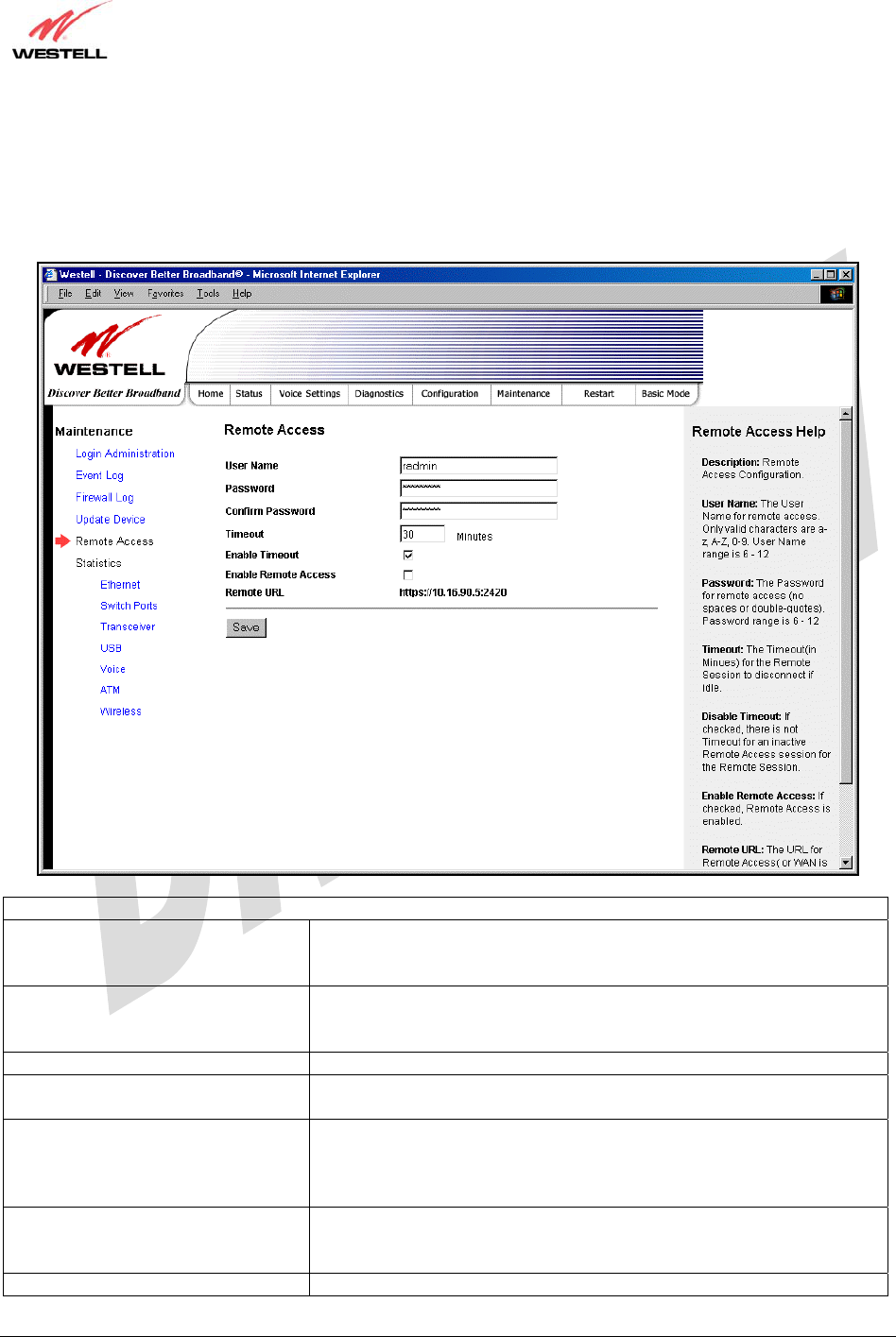
030-300479 Rev. A
Draft 1 – 10/17/05
030-300479 Rev. A 85 October 2005
User Guide UltraLine IIB (Model A90-816030)
16.5 Remote Access
The following screen will be displayed if you select Remote Access from the Maintenance menu. This screen
enables you to configure Remote Access for your Gateway. Enter the appropriates values in the fields provided and
then click Save to save the settings.
Remote Access
User Name The name used for Remote Access session. The only valid characters are
(a-z, A-Z, 0-9). The User Name must be at least 6 characters and must
not exceed 12 characters long.
Password The password used for Remote Access session. Do not use spaces or
double-quotes in the password. The password must be at least 6
characters and must not exceed 12 characters long.
Confirm Password Enter the same values as the password.
Timeout The interval (in minutes) after which the Remote Access session will
disconnect, if it is idle.
Enable Timeout Factory Default = Enable
If Enabled (box is checked) this will activate the Remote Access timeout
function.
If Disabled, the Remote Access timeout function will be deactivated.
Enable Remote Access Factory Default = Disable
If Enabled (box is checked), Remote Access will be activated.
If Disabled, Remote Access will be deactivated.
Remote URL Displays the URL for the Remote Access session.
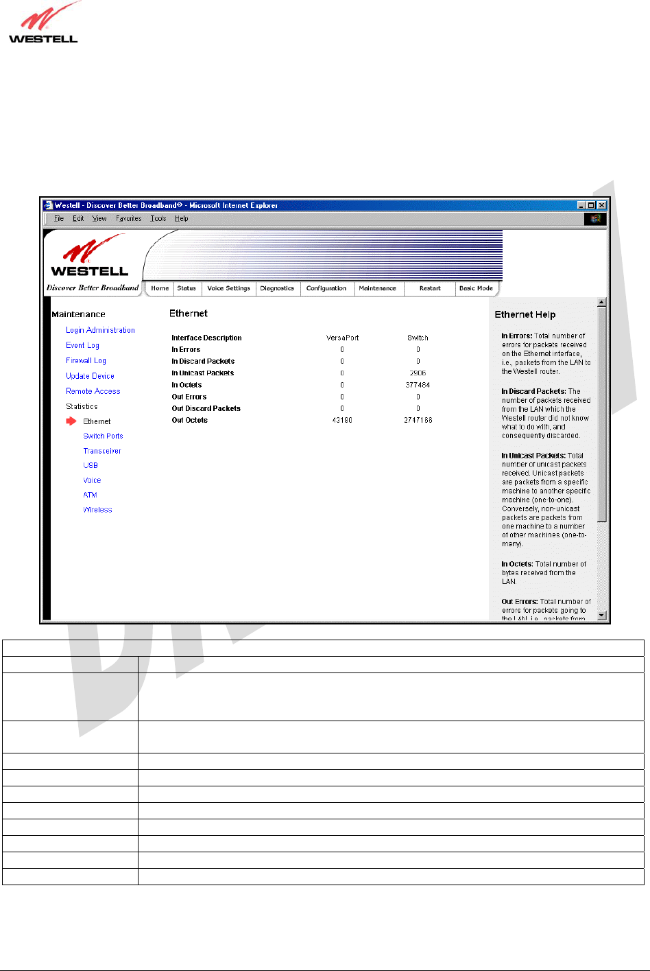
030-300479 Rev. A
Draft 1 – 10/17/05
030-300479 Rev. A 86 October 2005
User Guide UltraLine IIB (Model A90-816030)
16.6 Statistics
16.6.1 Ethernet Port Statistics
The following settings will be displayed if you select Statistics > Ethernet from the Maintenance menu.
Ethernet Port Statistics
Interface Description The description of the Ethernet interface on the Gateway.
VersaPort The VersaPort™2 on the rear of the Gateway. Note: When VersaPort is configured for
Private LAN mode via the modem’s VersaPort configuration screen, section 15.7.1,
VersaPort™2 functions as a fifth Ethernet switch, (E5).
Switch The Ethernet ports (E1, E2, E3, E4). Each functions as an Ethernet switch on the
Gateway.
In Errors The number of error packets received on the Ethernet interface.
In Discard Packets The number of discarded packets received.
In Unicast Packets The number of Unicast packets received on the Ethernet interface.
In Octets The number of bytes received on the Ethernet interface.
Out Errors The number of outbound packets that could not be transmitted due to errors.
Out Discard Packets The number of outbound packets discarded.
Out Unicast Packets The number of Unicast packets transmitted on the Ethernet interface.
Out Octets The number of bytes transmitted on the Ethernet interface.
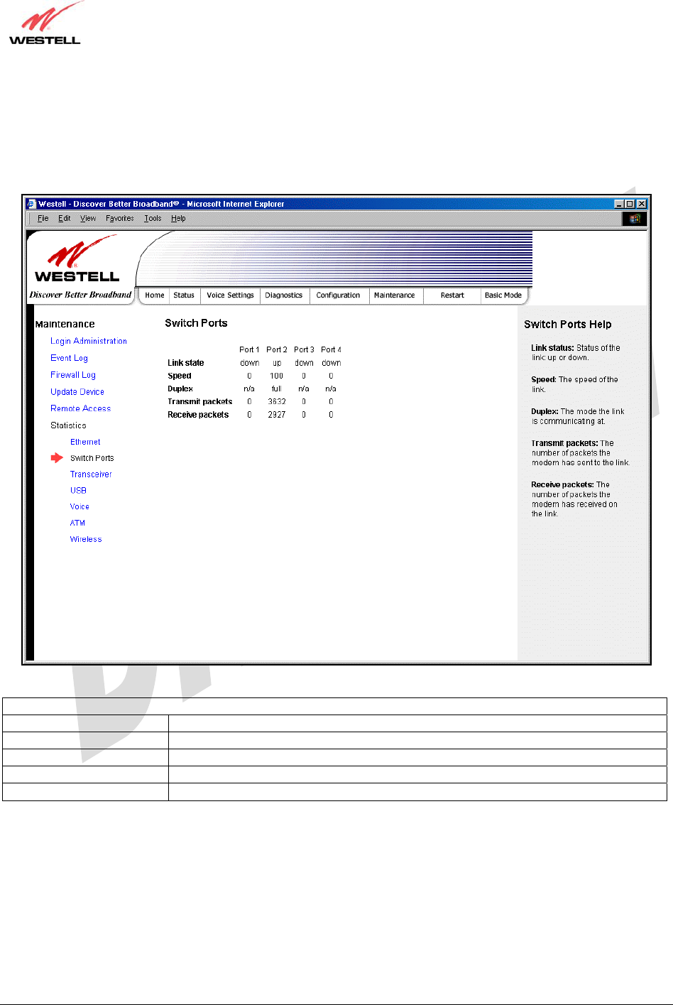
030-300479 Rev. A
Draft 1 – 10/17/05
030-300479 Rev. A 87 October 2005
User Guide UltraLine IIB (Model A90-816030)
16.6.2 Switch Ports Statistics
The following settings will be displayed if you select Statistics < Switch Ports from the Maintenance menu.
Switch Ports Statistics
Link State The status of the switch port.
Speed The negotiated speed of the Ethernet link.
Duplex The communication mode of the switch port.
Transmit Packets The number of Ethernet packets transmitted from this port
Receive Packets The number of Ethernet packets received on this port.
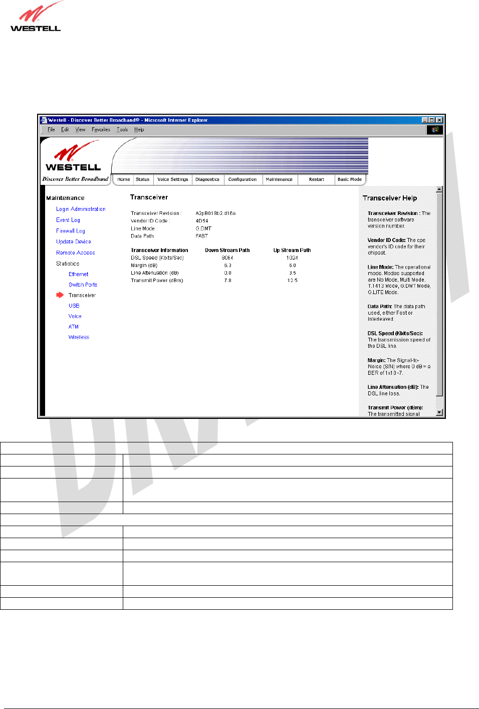
030-300479 Rev. A
Draft 1 – 10/17/05
030-300479 Rev. A 88 October 2005
User Guide UltraLine IIB (Model A90-816030)
16.6.3 Transceiver Statistics
The following settings will be displayed if you select Statistics < Transceiver from the Maintenance menu.
Transceiver Statistics
Transceiver Revision The transceiver software version number.
Vendor ID Code The CPE Vendor’s ID code for their chipset.
Line Mode The operational mode. Modes supported are No Mode, Multi Mode, T.1413
Mode, G.DMT Mode, and G.LITE Mode.
Data Path The data path used (either Fast or Interleaved).
Transceiver Information-Down Stream/Up Stream Path
Down Stream Path The path from the network to your Gateway.
Up Stream Path The path from your Gateway to the network.
DSL Speed (Kbits/Sec) The transmission rate that is provided by your Internet service provider (ISP).
SNR Margin (db) The Signal-to-Noise Ratio (S/N) where 0 db = a BER of 1x10⁻⁷, which inhibits
your DSL speed.
Line Attenuation (dB) The DSL line loss.
Transmit Power (db/Hz) The transmitted signal strength.
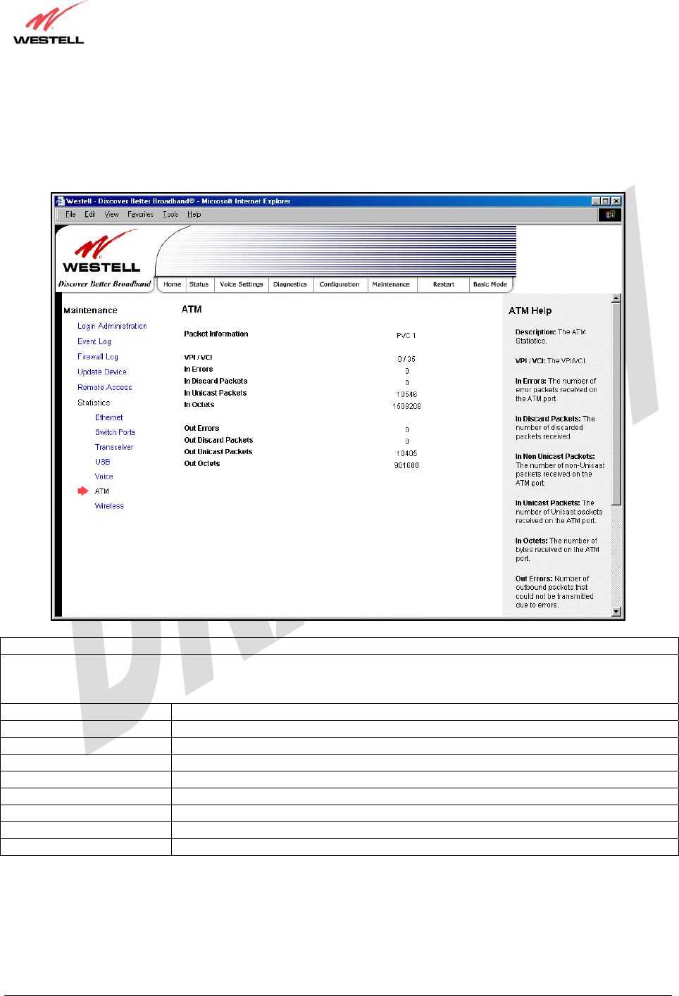
030-300479 Rev. A
Draft 1 – 10/17/05
030-300479 Rev. A 89 October 2005
User Guide UltraLine IIB (Model A90-816030)
16.6.4 ATM Statistics
The following settings will be displayed if you select Statistics < ATM from the Maintenance menu.
ATM Statistics
NOTE: Data listed in the OUT column pertains to transmissions from the Gateway’s ATM port to the Internet; the
Gateway is the source. Data listed in the IN column pertains to data received by the Gateway’s ATM port from the
Internet; the Gateway is the destination.
VPI/VCI Displays the VPI/VCI values obtained from your Internet Service Provider.
In Errors The number of error packets received on the ATM port.
In Discard Packets The number of discarded packets received.
In Unicast Packets The number of Unicast packets received on the ATM port.
In Octets The number of bytes received on the ATM port.
Out Errors The number of outbound packets that could not be transmitted due to errors.
Out Discard Packets The number of outbound packets discarded.
Out Unicast Packets The number of Unicast packets transmitted on the ATM port.
Out Octets The number of bytes transmitted on the ATM port.
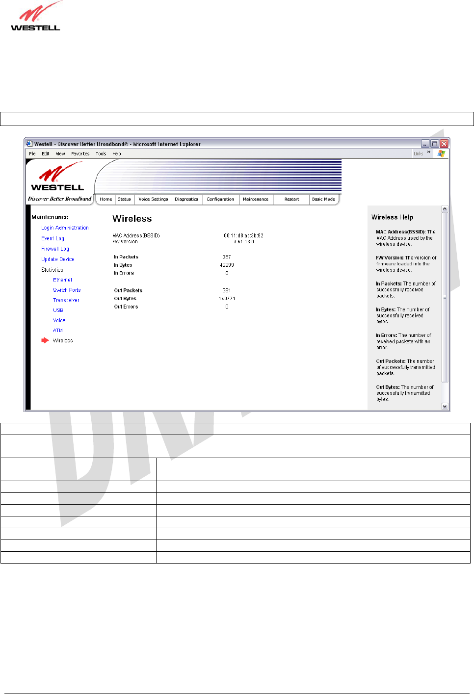
030-300479 Rev. A
Draft 1 – 10/17/05
030-300479 Rev. A 90 October 2005
User Guide UltraLine IIB (Model A90-816030)
16.6.5 Wireless Statistics
The following screen will be displayed if you select Statistics < Wireless from the Maintenance menu.
NOTE: The fields in this screen will be blank if no stations are associated with the AP.
Wireless Statistics
NOTE: Data listed in the OUT column pertains to transmissions from the AP to a station; the AP is the source. Data
listed in the IN column pertains to data received by the AP; the AP is the destination.
MAC Address (BSSID) This is the Media Access Controller (the hardware address of the Gateway).
It is also the Basic Service Set Identifier (BSSID) for your Gateway.
FW Version The version of application firmware.
In-Packets The number of successfully received packets.
In-Bytes The number of successfully received bytes.
In-Errors The number of received packets with an error.
Out-Packets The number of successfully transmitted packets.
Out-Bytes The number of successfully transmitted bytes.
Out-Errors The number of packets that did not transmit due to an error.

030-300479 Rev. A
Draft 1 – 10/17/05
030-300479 Rev. A 91 October 2005
User Guide UltraLine IIB (Model A90-816030)
17. NAT SERVICES
For your convenience, the Gateway supports protocols for Applications, Games, and VPN-specific programs. The
following chart provides port and protocol information for the services supported by the Gateway.
NOTE: To configure the Gateway for a service or application, follow the steps in section 15.2 (Port Forwarding) of
this User Guide.
Applications/Games/VPN Support
Application/Game Port/Protocol
Aliens vs. Predator 80 UDP, 2300 UDP, 8000-8999 UDP
Age of Empires II: The Conquerors 6073 UDP, 47624 TCP, 2300-2400 TCP/UDP
This service will open up ports for both traffic directions.
Americas Army TCP – 20045
UDP – 1716 to 1718, 8777, 27900
America Online 5190 TCP/UDP
Anarchy Online TCP/UDP – 7012,7013, 7500 -7505
AOL Instant Messenger 4099 TCP, 5190 TCP
Asheron's Call 9000-9013 UDP, 28800-29000 TCP
Battlecom 2300-2400 TCP/UDP, 47624 TCP/UDP
Battlefield 1942 UDP - 14567, 22000, 23000 to 23009, 27900, 28900
Black and White 2611-2612 TCP, 6667 TCP, 6500 UDP, 27900 UDP
Blizzard Battle.net (Diablo II) 4000 TCP, 6112 TCP/UDP
Buddy Phone 700, 701 UDP
Bungie.net, Myth, Myth II Server 3453 TCP
Calista IP Phone 3000 UDP, 5190 TCP
Citrix Metaframe 1494 TCP
Client POP/IMAP 110 TCP
Client SMTP 25 TCP
Counter Strike 27015 TCP/UDP, 27016 TCP/UDP
Dark Reign 2 26214 TCP/UDP
Delta Force ( Client and Server ) 3568 UDP, 3100-3999 TCP/UDP
Delta Force 2 3568-3569 UDP
DeltaForce: Land Warrior UDP 53
TCP 21
TCP 7430
TCP 80
UDP 1029
UDP 1144
UDP 65436
UDP 17478
DNS 53 UDP
Elite Force 2600 UDP, 27500 UDP, 27910 UDP, 27960 UDP
Everquest 1024-7000 TCP/UDP
F-16, Mig 29 3863 UDP
F-22 Lightning 3 4660-4670 TCP/UDP, 3875 UDP, 4533-4534 UDP, 4660-4670 UDP
F-22 Raptor 3874-3875 UDP
Fighter Ace II 50000-50100 TCP/UDP
Fighter Ace II for DX play 50000-50100 TCP/UDP, 47624 TCP, 2300-2400 TCP/UDP
FTP 20 TCP, 21 TCP
GameSpy Online UDP 3783

030-300479 Rev. A
Draft 1 – 10/17/05
030-300479 Rev. A 92 October 2005
User Guide UltraLine IIB (Model A90-816030)
UDP 6515
TCP 6667
UDP 12203
TCP/UDP 13139
UDP 27900
UDP 28900
UDP 29900
UDP 29901
Ghost Recon TCP 80
UDP 1038
UDP 1032
UDP 53
UDP 2347
UDP 2346
GNUtella 6346 TCP/UDP, 1214 TCP
Half Life Server 27005 UDP(client only)
27015 UDP
Heretic II Server 28910 TCP
Hexen II 26900 (+1) each player needs their own port. Increment by one for
each person.
Hotline Server 5500, 5503 TCP 5499 UDP
HTTPS 443 TCP/UDP
ICMP Echo 4 ICMP
ICQ OLD 4000 UDP, 20000-20019 TCP
ICQ 2001b 4099 TCP, 5190 TCP
ICUII Client 2000-2038 TCP, 2050-2051 TCP, 2069 TCP, 2085 TCP, 3010-3030
TCP
ICUII Client Version 4.xx 1024-5000 TCP, 2050-2051 TCP, 2069 TCP, 2085 TCP, 3010-3030
TCP, 2000-2038 TCP6700-6702 TCP, 6880 TCP, 1200-16090 TCP
IMAP 119 TCP/UDP
IMAP v.3 220 TCP/UDP
Internet Phone 22555 UDP
IPSEC ALG IPSEC ALG
IPSEC ESP PROTOCOL 50
IPSEC IKE 500 UDP
Ivisit 9943 UDP, 56768 UDP
JKII:JO (Jedi Knight II: Jedi Outcast) UDP - 28070 (default)
UDP- 27000 to 29000
KALI, Doom & Doom II 2213 UDP, 6666 UDP (EACH PC USING KALI MUST USE A
DIFFERENT PORT NUMBER STARTING WITH 2213 + 1)
KaZaA 1214 TCP/UDP
Limewire 6346 TCP/UDP, 1214 TCP
Medal Of Honor: Allied Assault TCP 80
UDP 53
UDP 2093
UDP 12201
TCP 12300
UDP 2135
UDP 2139
TCP/UDP 28900
mIRC Chat 6660-6669 TCP
Motorhead Server 16000 TCP/UDP, 16010-16030 TCP/UDP
MSN Game Zone 6667 TCP, 28800-29000 TCP
MSN Game Zone (DX 7 & 8 play) 6667 TCP, 6073 TCP, 28800-29000 TCP, 47624 TCP, 2300-2400

030-300479 Rev. A
Draft 1 – 10/17/05
030-300479 Rev. A 93 October 2005
User Guide UltraLine IIB (Model A90-816030)
TCP/UDP This service will open up ports for both traffic directions.
MSN Messenger 6891-6900 TCP, 1863 TCP/UDP, 5190 UDP, 6901 TCP/UDP
Napster 6699 TCP
Need for Speed 3, Hot Pursuit 1030 TCP
Need for Speed, Porsche 9442 UDP
Net2Phone 6801 UDP
NNTP 119 TCP/UDP
Operation FlashPoint 47624 UDP, 6073 UDP, 2300-2400 TCP/UDP, 2234 TCP
Outlaws 5310 TCP/UDP
Pal Talk 2090-2091 TCP/UDP, 2095 TCP, 5001 TCP, 8200-8700 TCP/UDP,
1025-2500 UDP
pcAnywhere host 5631 TCP, 5632 UDP, 22 UDP
Phone Free 1034-1035 TCP/UDP, 9900-9901 UDP, 2644 TCP, 8000 TCP
Quake 2 27910 UDP
Quake 3 27660 UDP
Each computer playing QuakeIII must use a different port number,
starting at 27660 and incrementing by 1. You'll also need to do the
following:
1. Right click on the QIII icon
2. Choose "Properties"
3. In the Target field you'll see a line like "C:\Program Files\Quake
III Arena\quake3.exe"
4. Add the Quake III net_port command to specify a unique
communication port for each system. The complete field should look
like this: "C:\Program Files\Quake III Arena\quake3.exe" +set
net_port 27660
5. Click OK.
6. Repeat for each system behind the NAT, adding one to the
net_port selected (27660,27661,27662)
Quicktime 4/Real Audio 6970-32000 UDP, 554 TCP/UDP
Rainbow Six & Rogue Spear 2346 TCP
RealOne Player TCP - 554, 7070 to 7071
UDP - 6970 to 7170
Real Audio 6970-7170 UDP
Return To Castle Wolfenstein Default -27960 TCP/UDP
UDP - 27950 to 27980
Roger Wilco TCP/UDP 3782
UDP 3783 (BaseStation)
SIP ALG SIP ALG
ShoutCast Server 8000-8005 TCP
Spinner Radio/Netscape Music TCP - 554
SSH Secure Shell 22 TCP/UDP
Starcraft 2346 TCP
Starfleet Command 2300-2400 TCP/UDP, 47624 TCP/UDP
SOF/SOFII (Soldier of Fortune /
Soldier of Fortune II) UDP - 28910 to 28915
Telnet 23 TCP
Tiberian Sun & Dune 2000 1140-1234, 4000 TCP/UDP
Tribes2 TCP - 15104, 15204, 15206, 6660 to 6699
UDP - 27999 to 28002
Ultima Online 5001-5010 TCP, 7775-7777 TCP, 8800-8900 TCP, 9999 UDP, 7875
UDP
Unreal Tournament server 7777 (default gameplay port)
7778 (server query port)

030-300479 Rev. A
Draft 1 – 10/17/05
030-300479 Rev. A 94 October 2005
User Guide UltraLine IIB (Model A90-816030)
7779,7779+ are allocated dynamically for each helper UdpLink
objects, including UdpServerUplin objects. Try starting with 7779-
7781 and add ports if needed.
27900 server query, if master server uplink is enabled. Home master
servers use other ports like 27500.
Port 8080 is for UT Server Admin. In the [UWeb.WebServer]
section of the server.ini file, set the ListenPort to 8080 and
ServerName to the IP assigned to the router from your ISP.
USENET News Service 143 TCP
VNC, Virtual Network Computing 5500 TCP, 5800 TCP, 5900 TCP
Westwood Online, C&C 4000 TCP/UDP, 1140-1234 TCP/UDP
World Wide Web (HTTP) 80 TCP
443 TCP (SSL)
8008 or 8080 TCP (PROXY)
Yahoo Messenger Chat 5000-5001 TCP
Yahoo Messenger Phone 5055 UDP
Xbox Live 88 TCP/UDP, 3074 TCP/UDP
IPSec Encryption IPSec using AH can not be supported through NAT. IPSec using
ESP and L2TP can be supported via an ALG
L2TP IPSec using ESP and L2TP can be supported via an ALG.
PPTP Works through NAT.

030-300479 Rev. A
Draft 1 – 10/17/05
030-300479 Rev. A 95 October 2005
User Guide UltraLine IIB (Model A90-816030)
18. PRODUCT SPECIFICATIONS
Data Features
• Network Address Port Translation
• DHCP client/server
• DNS server/relay
• Static Routes
• Dynamic Routing with RIP v1 and v2
• PPTP/L2TP/IPSEC VPN NAPT passthrough
• NAT ALG support for common applications
• Stateful Inspection Firewall with logging
• Diffserv IP QOS
ADSL WAN
DSL Standards
• ANSI T1.413 issue 2
• ITU G.992.1 (G.DMT) and S=1/2
• ITU G.992.2 (G.lite)
• ITU G.992.3 (ADSL2 DMT)
• ITU G.992.3 Annex L READSL
• ITU G.992.5 (ADSL2+)
• ITU G.994.1 (G.HS)
WAN Protocol Features
• Bridge Encapsulation per RFC 1483
• Routed IP over ATM per RFC 2684
• PPP over Ethernet per RFC 2516
• PPP over ATM per RFC 2364
• Auto Protocol Detect
ATM Features
• Multi PVC support
• Auto PVC detect
• CBR, VBR-rt, VBR-nrt and UBR traffic
shaping
• OAM F4/F5 Loop-back
Public LAN Features
• Dedicated DMZ port
• DHCP server
• Bridge mode mapped to a separate PVC
Ethernet LAN
• Four port 10/100 Base-T Ethernet switch
• Auto MDI/MDI-X detection
• VLAN tagging
Wireless LAN
• IEEE 802.11b/g with frame bursting
• WEP and WPA-PSK security
• MAC address filtering
• Upgradable to 802.11i, 802.11e, WME
• High gain removable external antenna
Management
• Web-based GUI
• Remote management via TR-069 or WT-087
System Requirements
Ethernet
• Pentium® or equivalent and above machines
• Microsoft Windows (98 SE, 2000, ME, NT
4.0, or XP), Macintosh OS X, or Linux
installed
• Internet Explorer 4.x or Netscape Navigator
4.x or higher
• Ethernet 10/100 Base-T interface
• TCP/IP Protocol stack installed
Wireless
• Pentium® or equivalent and above class
machines
• Microsoft® Windows® (98 ME, 2000, or XP)
or Macintosh® OS X installed
• Operating System CD on hand
• Internet Explorer 4.x or Netscape Navigator
4.x or higher
• 64 MB RAM (128 MB recommended)
• 10 MB of free hard drive space
• IEEE 802.11b/g/g+ PC adapter
Physical Specifications
Dimensions/Weight
• Height: 1.5 in (3.81 cm)
• Width: 10.0 in (25.4 cm)
• Depth: 6.50 in (16.5 cm)
• Weight: Approx. 1.26 lbs. (0.57 kg)
Environmental
• Ambient Operating Temperature: +32° to
+104° F (0° to +40° C)
• Relative Humidity: 5 to 95%, non-condensing
Network Interface
• WAN: DSL RJ-11 port (to ADSL-provisioned jack)
• LAN: 10/100 Base-T RJ-45 port (to PC or Hub)

030-300479 Rev. A
Draft 1 – 10/17/05
030-300479 Rev. A 96 October 2005
User Guide UltraLine IIB (Model A90-816030)
Power
• Power Adapter:
Input: AC 120V/
Output: DC +12V
• Power Consumption: Less than 14W typical
from 120 VAC
LED Indicators
• PWR
• Ethernet (E1, E2, E3, E4)
• WiFi
• DSL (DSL2, DSL1)
• BONDED
• INTERNET
Connectors
• Two DSL: 6-pin (RJ-11)
• Four Ethernet: 8-pin RJ-45
• Power: Barrel connector
• Wireless IEEE 802.11b/g SMA connector/antenna
Compliance
EMC
• FCC Part 15 Class B, subpart C
Safety
• ANSI/UL 60950-1
• CAN/CSA C22.2 No. 60950-1 First Edition
dated April 1, 2003 with revisions through
November 26, 2003
Regulatory Approval
• UL, CSA, FCC Part 68, ACTA 968-A-3
Industry Canada CS03, GR-1089-CORE

030-300479 Rev. A
Draft 1 – 10/17/05
030-300479 Rev. A 97 October 2005
User Guide UltraLine IIB (Model A90-816030)
19. TECHNICAL SUPPORT INFORMATION
Westell Technical Support
If technical assistance is required, contact your Internet service provider first for support. Westell technical support
can be reached by calling:
North America U.K./Europe
Phone: 1-630-375-4500 Phone: (44) 01256 843311
Visit Westell at www.Westell.com to view frequently asked questions and enter on-line service requests, or send
email to global_support@westell.com to obtain additional information.
20. WARRANTY AND REPAIRS
Warranty
Westell warrants this product free from defects at the time of shipment. Westell also warrants this product fully
functional for the period specified by the terms of the warranty. Any attempt to repair or modify the equipment by
anyone other than an authorized representative will void the warranty.
Repairs
Westell will repair any defective Westell equipment without cost during the warranty period if the unit is defective
for any reason other than abuse, improper use, or improper installation, or acts of nature. Before returning the
defective equipment, request a Return Material Authorization (RMA) number from Westell. An RMA number
must be quoted on all returns. When requesting an RMA, please provide the following information:
• Product model number (on product base)
• Product serial number (on product base)
• Customer ship-to address
• Contact name
• Problem description
• Purchase date
After an RMA number is obtained, return the defective unit, freight prepaid, along with a brief description of the
problem to one of the following options:
North America U.K./Europe
Westell, Inc. Westell, Ltd.
ATTN: R.G.M Department Ringway House
750 N. Commons Drive Bell Road
Aurora, IL 60504-7940 USA Daneshill
Basingstoke
RG24 8FB
United Kingdom
Westell will continue to repair faulty equipment beyond the warranty period for a nominal charge. Contact a Westell
Technical Support Representative for details.

030-300479 Rev. A
Draft 1 – 10/17/05
030-300479 Rev. A 98 October 2005
User Guide UltraLine IIB (Model A90-816030)
21. PUBLICATION INFORMATION
Westell® UltraLine IIB (Model A90-816030)
Document Part Number 030-300479 Rev. A
Copyright © 2005 Westell, Inc.
All rights reserved.
Westell, Inc.
750 North Commons Drive
Aurora, Illinois 60504 USA
www.westell.com
All trademarks and registered trademarks are the property of their respective owners.