Westell B755 VersaLink Wireless Gateway User Manual B90 7550 UserGuide
Westell Inc VersaLink Wireless Gateway B90 7550 UserGuide
UserManual.wiki
>
Westell
>
B755 User Manual
User Manual II
Navigation menu
Upload a User Manual
Namespaces
Wiki Guide
HTML
PDF
Info
Views
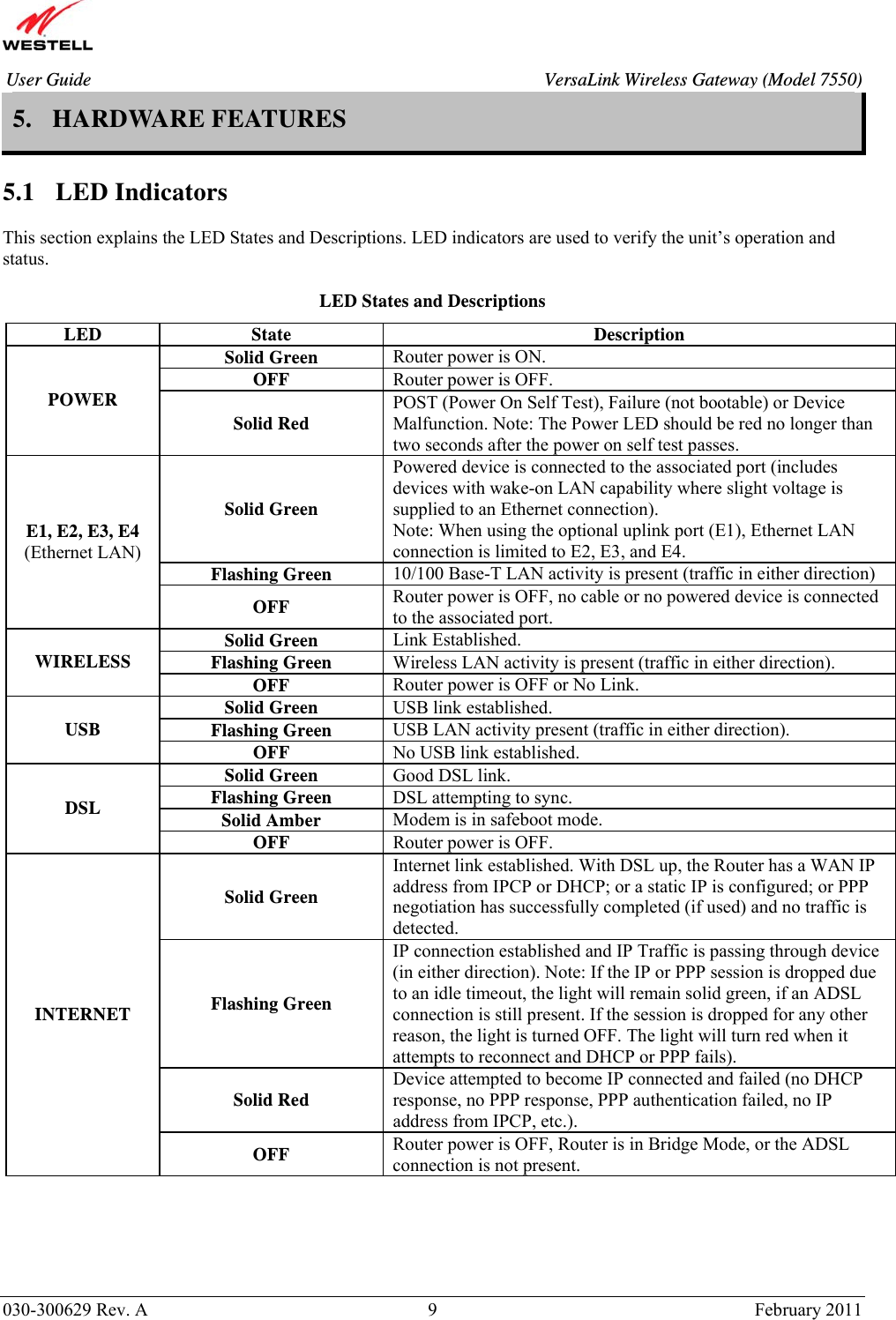
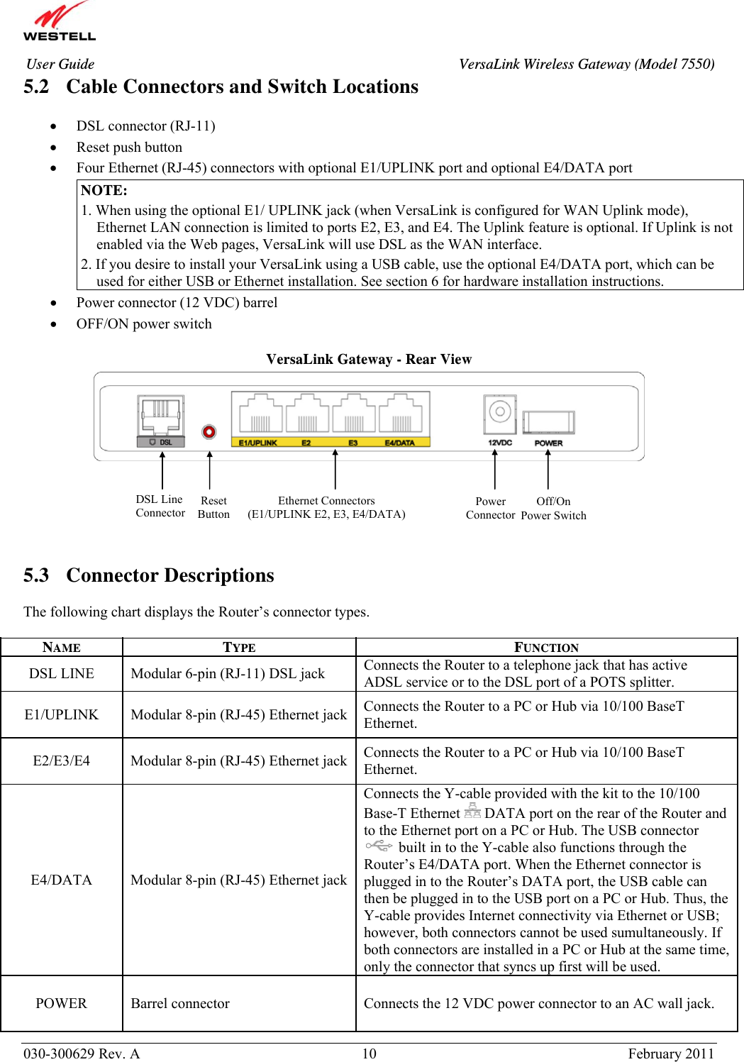
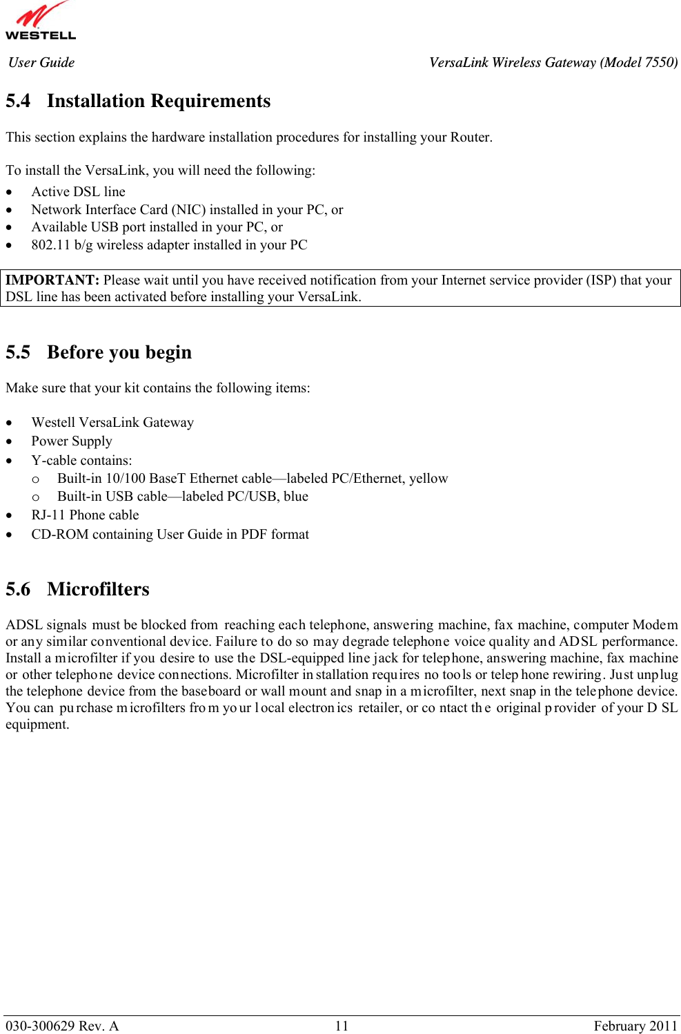
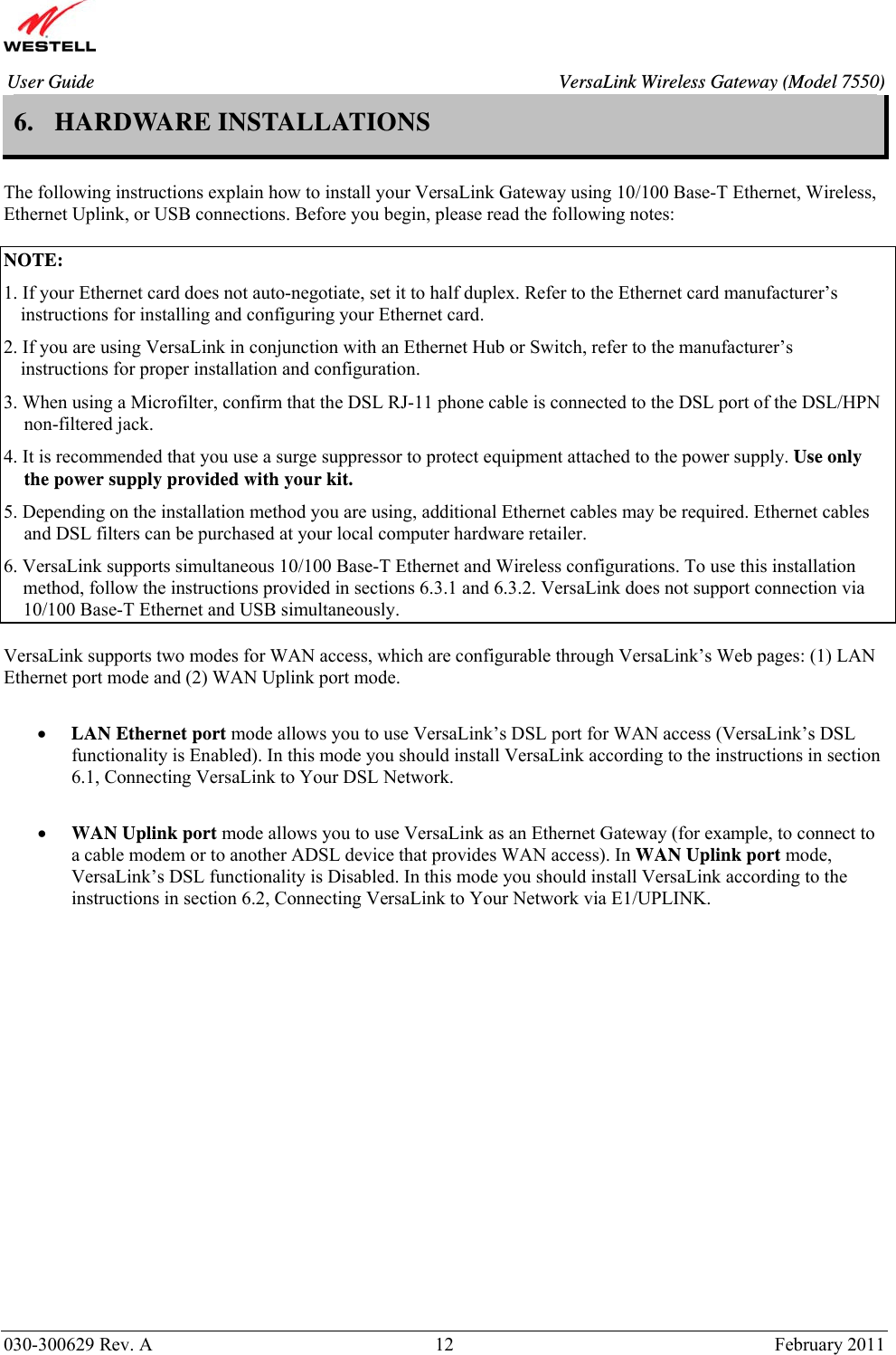
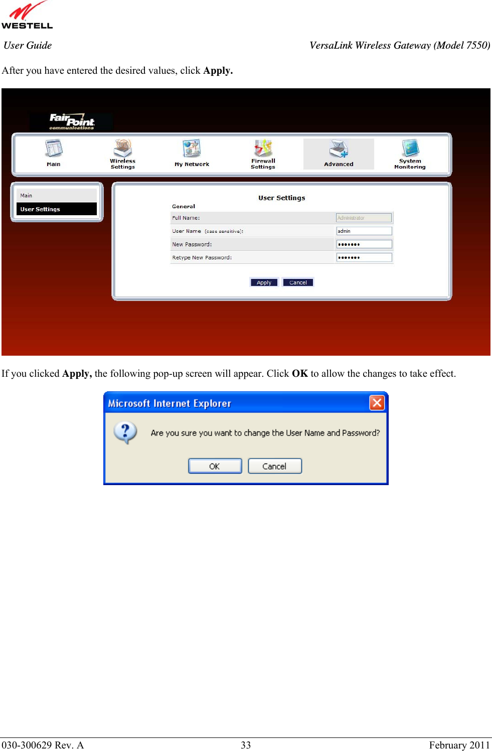
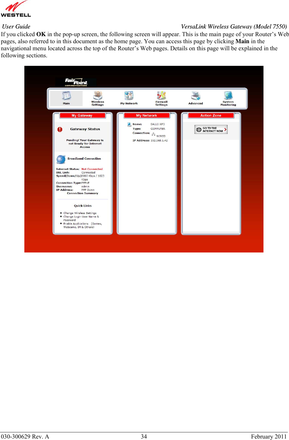
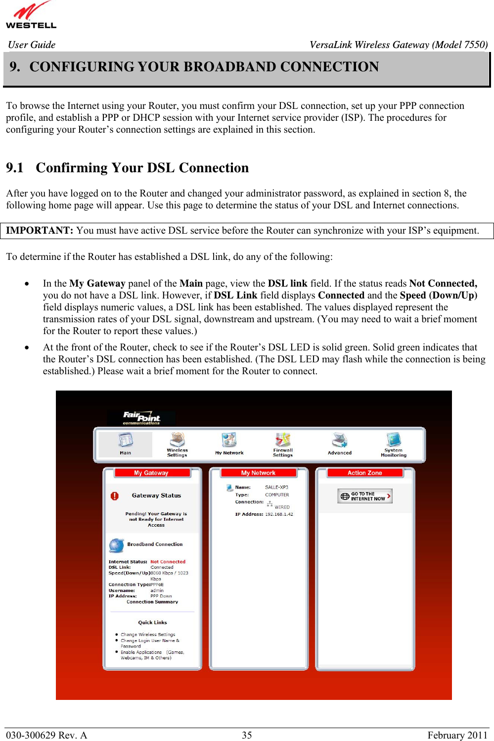
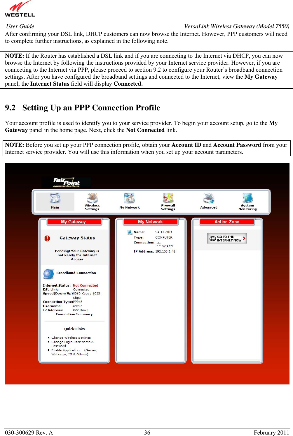
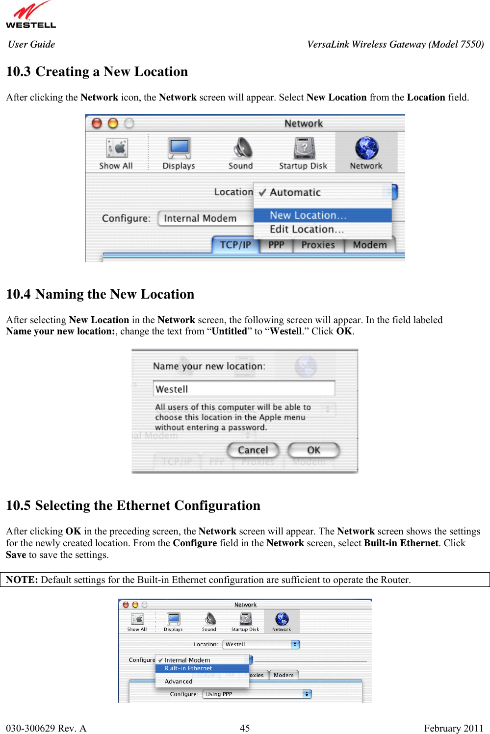
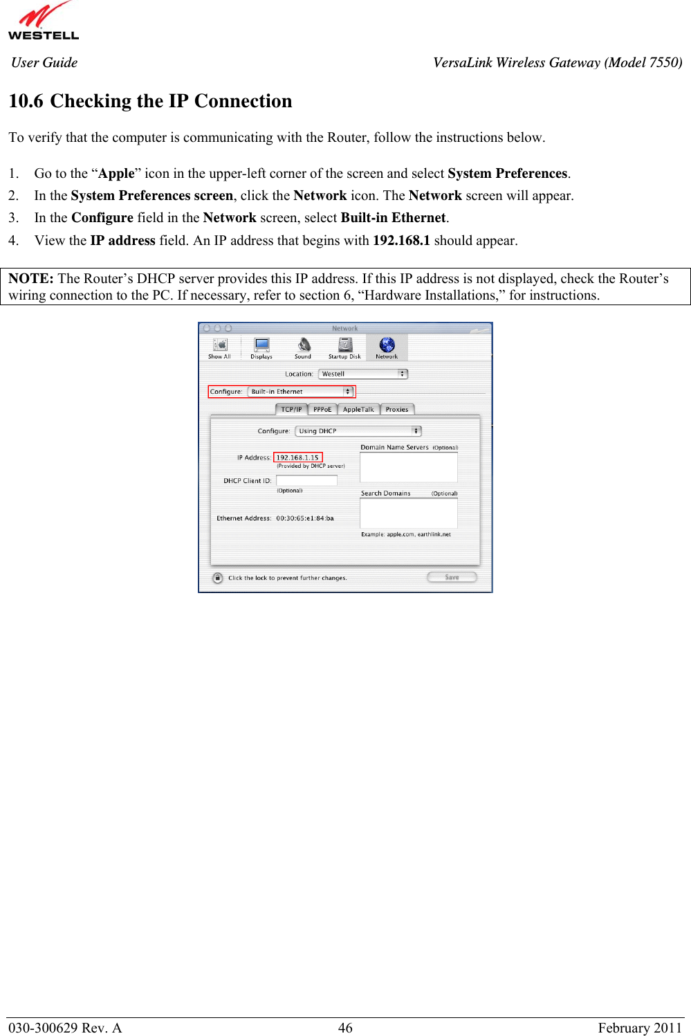
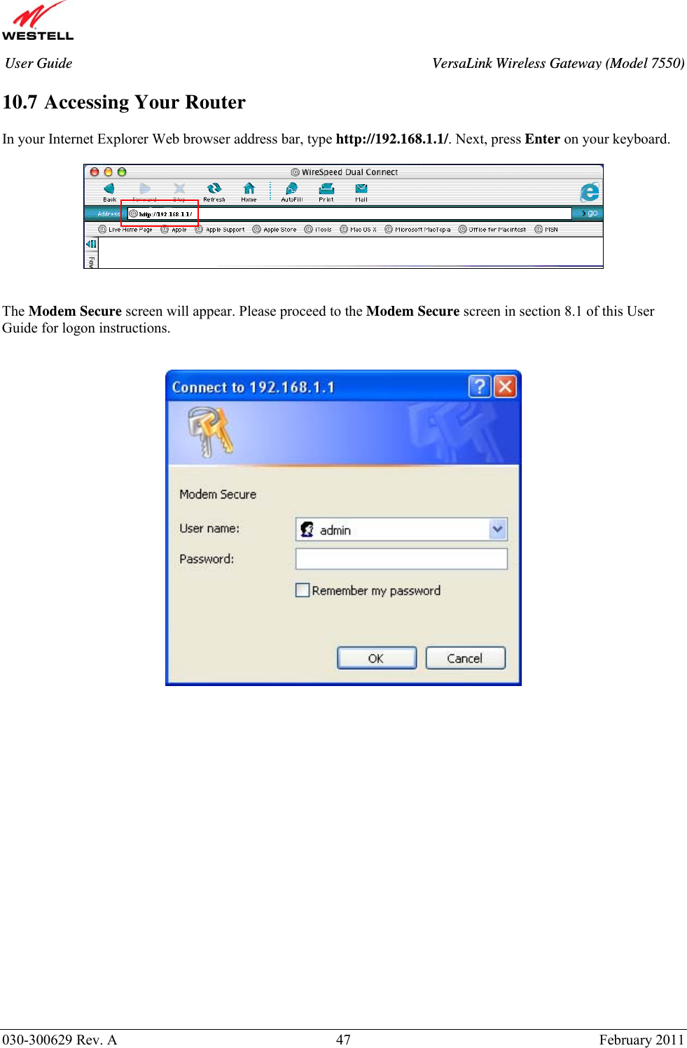
User Manual
Discussion / Help
Navigation