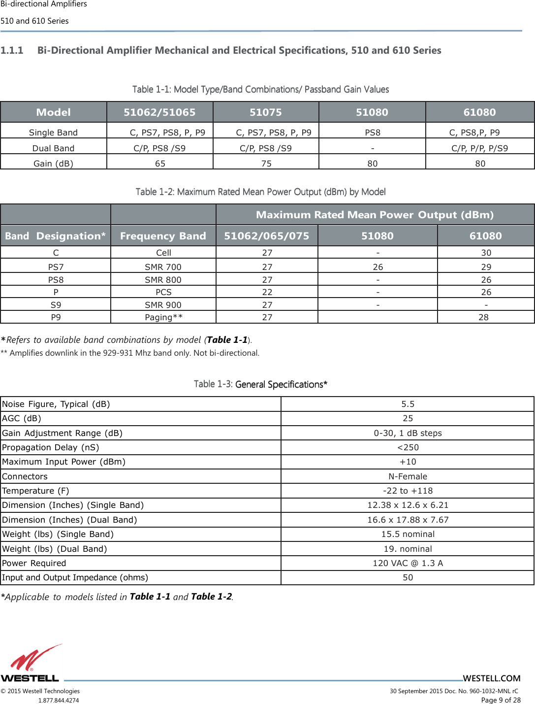
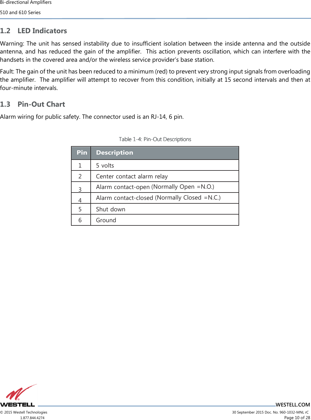
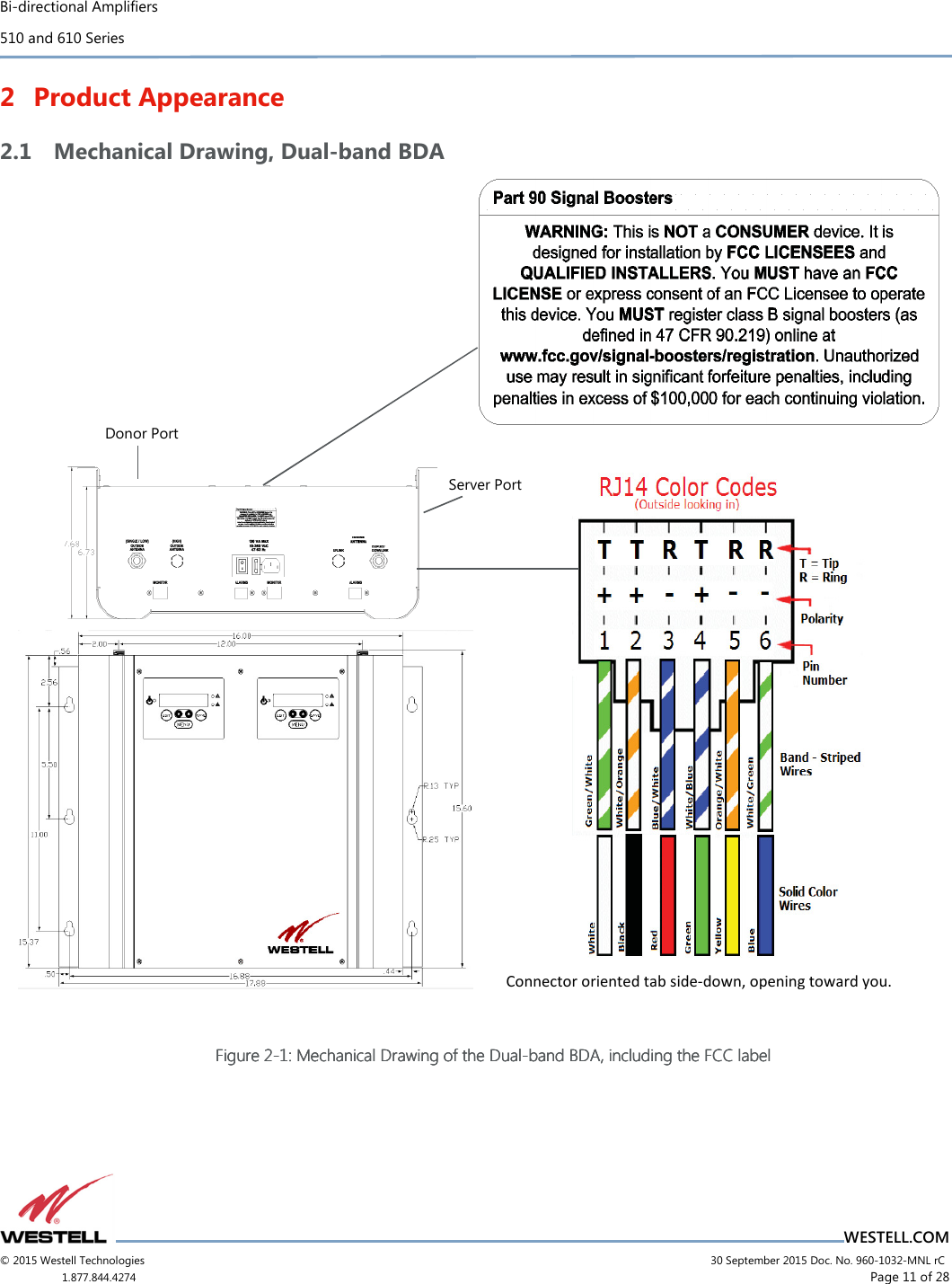
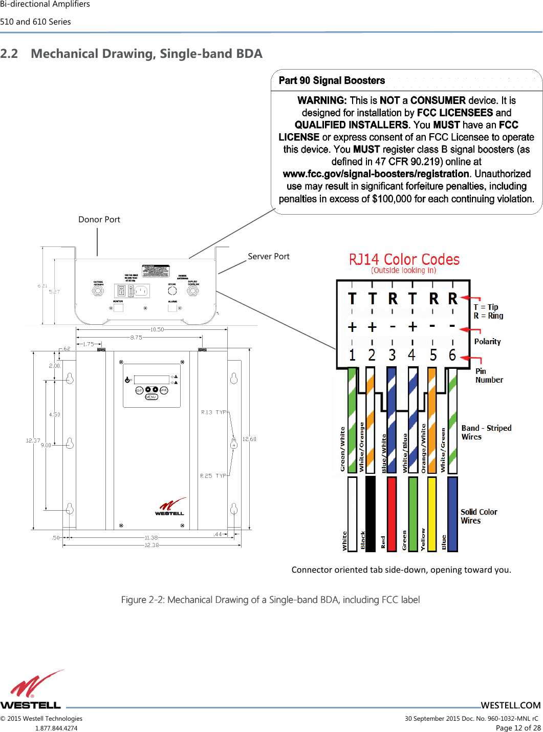
Westell BDA510-P9 In Building Amplifier User Manual Manual

Westell, Inc. In Building Amplifier Manual

Manual

PRODUCT MANUAL                                   WESTELL.COM ©Westell Technologies. 960-1032-MNL rC              Bi-directional Amplifiers  510 and 610 Series
Bi-directional Amplifiers 510 and 610 Series                                    WESTELL.COM © 2015 Westell Technologies                             30 September 2015 Doc. No. 960-1032-MNL rC 1.877.844.4274                     Page 2 of 28  Disclaimer All information and statements contained herein are accurate to the best of the knowledge of Westell, but Westell makes  no  warranty with  respect  thereto, including  without  limitation  any  results that may  be  obtained  from  the products described herein or the infringement by such products of any proprietary rights of any persons.  Use or application of such information or statements is at the users’ sole risk, without any liability on the part of Westell.  Nothing herein shall be construed as license or recommendation for use, which infringes upon any proprietary rights of any person.  Product material and specifications are subject to change without notice.  Westell’s standard terms of sale and the specific terms of any particular sale apply.  WARNING. This is NOT a CONSUMER device. It is designed for installation by FCC LICENSEES and QUALIFIED INSTALLERS. You must have an FCC LICENSE or express consent of an FCC Licensee to operate this device.  Unauthorized use may result in significant forfeiture penalties, including penalties in excess of $100,000 for Each continuing violation.”  WARNING! Changes and Modifications not expressly approved by Westell can void your authority to operate this equipment under Federal Communications Commission’s rules. WARNING! The Manufacturer's rated output power of this equipment is for single carrier operation. For situations when multiple carrier signals are present, the rating would have to be reduced by 3.5 dB, especially where the output signal is re-radiated and can cause interference to adjacent band users. This power reduction is to be by means of input power or gain reduction and not by an attenuator at the output of the device.   . STATE DEPARTMENT EXPORT AUTHORIZATION REQUIRED FOR DISTRIBUTION TO FOREIGN DESTINATIONS OR FOREIGN PERSONS  This document contains Technical Data controlled under the US International Traffic in Arms Regulations (ITAR), 22 CFR 120-130, and may not be exported or transferred to any Foreign Person, foreign country or foreign entity, by any means, without prior written approval from the U.S. Department of State, Directorate of Defense Trade Controls (“DDTC”) and DRS ICAS, LLC.
Bi-directional Amplifiers 510 and 610 Series                                    WESTELL.COM © 2015 Westell Technologies                             30 September 2015 Doc. No. 960-1032-MNL rC 1.877.844.4274                     Page 3 of 28   TABLE OF CONTENTS Disclaimer ........................................................................................................................................................................................................ 2 Preface ........................................................................................................................................................................... 6 Purpose............................................................................................................................................................................................................. 6 Application ...................................................................................................................................................................................................... 6 Product Registration Information .......................................................................................................................................................... 6 Safety Guidelines .......................................................................................................................................................................................... 6 Important Safety Information .................................................................................................................................................................. 7 1 Overview ............................................................................................................................................................... 8 1.1 Product Information ..................................................................................................................................................................... 8 1.1.1 Bi-Directional Amplifier Mechanical and Electrical Specifications, 510 and 610 Series  9 1.2 LED Indicators ............................................................................................................................................................................... 10 1.3 Pin-Out Chart ................................................................................................................................................................................ 10 2 Product Appearance .......................................................................................................................................... 11 2.1 Mechanical Drawing, Dual-band BDA ................................................................................................................................ 11 2.2 Mechanical Drawing, Single-band BDA ............................................................................................................................. 12 3 Installation Tips .................................................................................................................................................. 13 3.1 Important Installation Tips ...................................................................................................................................................... 13 3.2 Standard Single Internal Antenna System Design ......................................................................................................... 13 3.3 Troubleshooting .......................................................................................................................................................................... 14 3.4 Optional Accessories ................................................................................................................................................................. 14 4 LCD Command Interface ................................................................................................................................... 15 4.1 Command Interface Overview ............................................................................................................................................... 15 4.2 The View Menu Series ............................................................................................................................................................... 15 4.2.1 Screen Saver Display  17 4.2.2 Power Readings Display 17 4.2.3 Event Readout Displays  18 4.2.4 Peak Power Readout Display  19 4.2.5 Gain Display  19 4.2.6 BDA Name and Address Display 19 4.3 The Edit Menu Series ................................................................................................................................................................. 21
Bi-directional Amplifiers 510 and 610 Series                                    WESTELL.COM © 2015 Westell Technologies                             30 September 2015 Doc. No. 960-1032-MNL rC 1.877.844.4274                     Page 4 of 28  4.3.1 Edit Events Display  22 4.3.2 Edit Peak Power Readout Display  22 4.3.3 Edit Downlink Gain Display  22 4.3.4 Edit Uplink Gain Display 23 4.3.5 Edit BDA Name Display  23 4.3.6 Edit BDA Address Display  24 4.3.7 Software Shutdown Display  25 4.3.8 Create New Password Display  25 5 Registration Numbers ....................................................................................................................................... 27 Appendix A Glossary ............................................................................................................................................ A   TABLE OF FIGURES Figure 1-1: Product Registration Information ............................................................................................................................................. 6 Figure 2-1: Mechanical Drawing of the Dual-band BDA, including the FCC label ..................................................................... 11 Figure 2-2: Mechanical Drawing of a Single-band BDA, including FCC label .............................................................................. 12 Figure 3-1: Standard Single Internal Antenna System Design ........................................................................................................... 13 Figure 4-1: View Menu Series .......................................................................................................................................................................... 16 Figure 4-2: Screen Saver Display .................................................................................................................................................................... 17 Figure 4-3: Power Readings Display ............................................................................................................................................................. 17 Figure 4-4: Events Readout Displays ............................................................................................................................................................ 18 Figure 4-5: Peak Power Readout Display .................................................................................................................................................... 19 Figure 4-6: Gain Display ..................................................................................................................................................................................... 19 Figure 4-7: BDA Name and Address Display ............................................................................................................................................. 20 Figure 4-8: Password entry display................................................................................................................................................................ 20 Figure 4-9: Edit Menu Series ............................................................................................................................................................................ 21 Figure 4-10: Edit Events Display ..................................................................................................................................................................... 22 Figure 4-11: Edit Peak Power Readout Display ........................................................................................................................................ 22 Figure 4-12: Edit Downlink Gain Display ..................................................................................................................................................... 23
Bi-directional Amplifiers 510 and 610 Series                                    WESTELL.COM © 2015 Westell Technologies                             30 September 2015 Doc. No. 960-1032-MNL rC 1.877.844.4274                     Page 5 of 28  Figure 4-13: Edit Uplink Gain Display ........................................................................................................................................................... 23 Figure 4-14: Edit BDA name display menu................................................................................................................................................. 24 Figure 4-15: Example display when editing the BDA Name ................................................................................................................ 24 Figure 4-16: Another display when editing the BDA Name ................................................................................................................ 24 Figure 4-17: Edit BDA Address Display ........................................................................................................................................................ 24 Figure 4-18: Software shutdown display ..................................................................................................................................................... 25 Figure 4-19: Old password display ................................................................................................................................................................ 25 Figure 4-20: New password display .............................................................................................................................................................. 26  TABLE OF TABLES Table 1-1: Model Type/Band Combinations/ Gain Values ..................................................................................................................... 9 Table 1-2: Maximum Power Output (dBm) by Model.............................................................................................................................. 9 Table 1-3: General Specifications* ................................................................................................................................................................. 9 Table 1-4: Pin-Out Descriptions ..................................................................................................................................................................... 10 Table A-1: Acronyms and Abbreviations ....................................................................................................................................................... A
Bi-directional Amplifiers 510 and 610 Series                                    WESTELL.COM © 2015 Westell Technologies                             30 September 2015 Doc. No. 960-1032-MNL rC 1.877.844.4274                     Page 6 of 28  Preface Purpose  The purpose of this  document  is  to  provide  instructions  to  help  the  experienced technician/engineer  install and commission  an  in-building  wireless  enhancement  system  using  Westell  Technologies  Bi-Directional  Amplifiers.  Following the procedures outlined will minimize risks associated with modifying a live system and preclude service interruptions.  This document assumes the technician/engineer understands the basic principles and functionality involved with repeater and in-building systems and addresses the practical concerns of the installation procedure. Application  Apply this guide whenever a need exists to add enhanced signal capability to an existing system or when the repeater is being included in a new installation. Product Registration Information The serial number is located on the label on the bottom panel, near the power connectors.  Write this number in the boxes shown in Figure 1-1.  Retain this manual, along with proof of purchase, to serve as a permanent record of your purchase.  Figure Figure Figure Figure 1111----1111: Product Registration Information: Product Registration Information: Product Registration Information: Product Registration Information    Safety Guidelines The general safety information in this guideline applies to both operating and service personnel.  Specific warnings and cautions are located in other parts of this manual where they apply, but may not appear in this summary.  Failure to comply with these precautions or specific warnings elsewhere in the manual violates safety standards of design, manufacture, and intended use of equipment.  Westell assumes no liability for the customer’s failure to comply with these requirements: Grounding:    This  bi-directional  amplifier  is  designed  to  operate  from  100-240  VAC  and  should  always  be operated with the ground wire properly connected.  Do not remove or otherwise alter the grounding lug on the power cord. Explosive atmospheres:  To avoid explosion or fire, do not operate this product in the presence of flammable gases or fumes. Lightning danger:   Do not  install  or  adjust this unit during an electrical storm.   Use of a suitable lightning arrester, such as Westell’s model number CSI-CAP, is strongly recommended.
Bi-directional Amplifiers 510 and 610 Series                                    WESTELL.COM © 2015 Westell Technologies                             30 September 2015 Doc. No. 960-1032-MNL rC 1.877.844.4274                     Page 7 of 28  There are no user-serviceable parts inside.  Hazardous voltages are present when the cover is removed.  Opening the chassis  will void  your  warranty.  If  you  suspect a  malfunction  with  this product, call  your  dealer  or  Westell’s Technical Support line at 1-877-844-4274.  It is recommended that the unit be powered down when connecting and disconnecting cables.   Important Safety Information WARNING! Changes and Modifications not expressly approved by Westell can void your authority to operate this equipment under Federal Communications Commission’s rules. An  omni-directional  antenna  with  a  maximum  gain  of  3  dBi  is  authorized  for  indoor  use  with  these  units.    The maximum rated mean output power is 30dBm for the Cell band models therefore the maximum ERP is 2 watts or less for all units.  Inside antennas must be positioned to observe minimum separation of 20 cm (~8 in) from all users and bystanders.  For the protection of personnel working in the vicinity of inside (downlink) antennas, the following guidelines for minimum distances between the human body and the antenna must be observed. Under normal conditions, no personnel can come within 20 cm (~ 8 in) from any inside antenna during the installation of an indoor antenna.  This minimum separation will ensure that the employee or bystander does not receive RF-exposure  beyond  the  maximum  permissible  exposure  according  to  section  1.1310  i.e.  limits  for  general population/uncontrolled exposure. For outdoor use, a directional antenna up to a maximum gain of 11 dBi is authorized for use with this unit.  The outside antenna must be positioned to observe minimum separation of 120 cm (~4 ft) from all users and bystanders.  For  the  protection of  personnel working  in  the vicinity  of  outside  (uplink) antennas, the following  guidelines  for minimum distances between the human body and the antenna must be observed.  The installation of an outdoor antenna must be such that, under normal conditions, no personnel can come within 120 cm (~ 4 ft) from the outside antenna.  In all installations, the antenna should never be mounted such that the main  beam  is  directed  toward  an  area  where  workers  or  bystanders  may  be  present.    Exceeding  this  minimum separation will ensure that the worker or bystander does not receive RF-exposure beyond the maximum permissible exposure according to section 1.1310 i.e. limits for general population/uncontrolled exposure.  The guidelines for the uplink outdoor antenna are not applicable to the P9 paging model since it is not bi-directional. The P9 only amplifies the downlink in a nominal bandwidth of 2 mhz from 929-931 mhz.
Bi-directional Amplifiers 510 and 610 Series                                    WESTELL.COM © 2015 Westell Technologies                             30 September 2015 Doc. No. 960-1032-MNL rC 1.877.844.4274                     Page 8 of 28  1 Overview 1.1 Product Information Westell developed the Bi-Directional Amplifier (BDA) for use in enclosed structures where sufficient signal from local cell sites to operate cell phones was unavailable within the building.  Sufficient signal must be available on the roof of the structure.  The BDA is connected to an external antenna, usually on the roof, and to one or more internal antennas placed strategically throughout the area where phone service is desired. The  external  antenna  is usually  a  directional  type  such  as  a  yagi.    Internal  antennas  are  usually  omnidirectional, although various other types may be used for certain installations.  The BDA amplifies both the uplink (phone to tower) and downlink (tower to phone) signals thus facilitating communications to and from the local cell site. The exception to this is the P9 paging model which amplifies the downlink only. There are seven amplification stages on the downlink and seven on the uplink for a total of 65 to 80 dB nominal gain for each link.  Gain can be set using the LCD display and pressing the up and down buttons.  There are also LED indicators on the top cover for power overload and gain reduction to prevent oscillation.  WARNING FOR PUBLIC SAFETY MODELS  The  bi-directional  amplifier  (BDA)  is  not  a  consumer  device.    This  product  is designed for installation by FCC licensees and qualified users.  You must have an FCC LICENSE or express consent of an FCC Licensee to operate this device.  You must  register  class  B  signal  boosters  (as  defined  in  47  CFR  90.219)  online  at www.fcc.gov/signal-boosters/registration.    Unauthorized  use  may  result  in significant forfeiture penalties, including penalties in excess of $100,000 for each continuing violation.
Bi-directional Amplifiers 510 and 610 Series                                    WESTELL.COM © 2015 Westell Technologies                             30 September 2015 Doc. No. 960-1032-MNL rC 1.877.844.4274                     Page 9 of 28  1.1.1 Bi-Directional Amplifier Mechanical and Electrical Specifications, 510 and 610 Series  Table Table Table Table 1111----1111::::    ModelModelModelModel    Type/Band Combinations/ Type/Band Combinations/ Type/Band Combinations/ Type/Band Combinations/ Passband Passband Passband Passband Gain ValuesGain ValuesGain ValuesGain Values    Model 51062/51065 51075 51080 61080 Single Band C, PS7, PS8, P, P9 C, PS7, PS8, P, P9 PS8         C, PS8,P, P9 Dual Band C/P, PS8 /S9 C/P, PS8 /S9 - C/P, P/P, P/S9 Gain (dB) 65 75 80 80  Table Table Table Table 1111----2222: : : : Maximum Maximum Maximum Maximum Rated Rated Rated Rated Mean Mean Mean Mean Power Output (dBm) by ModelPower Output (dBm) by ModelPower Output (dBm) by ModelPower Output (dBm) by Model       Maximum Rated Mean Power Output (dBm) Band  Designation* Frequency Band 51062/065/075 51080  61080 C Cell 27 - 30 PS7 SMR 700 27 26 29 PS8 SMR 800 27 - 26 P PCS 22 - 26 S9 SMR 900 27 - - P9 Paging** 27                 28  *Refers to available band combinations by model (Table 1-1). ** Amplifies downlink in the 929-931 Mhz band only. Not bi-directional.  Table Table Table Table 1111----3333: : : : General General General General SpeciSpeciSpeciSpecificationsficationsficationsfications****        Noise Figure, Typical  (dB) 5.5 AGC (dB) 25 Gain Adjustment Range (dB)  0-30, 1 dB steps Propagation Delay (nS) <250 Maximum Input Power (dBm) +10 Connectors N-Female Temperature (F)  -22 to +118 Dimension (Inches) (Single Band)  12.38 x 12.6 x 6.21 Dimension (Inches) (Dual Band)  16.6 x 17.88 x 7.67 Weight (lbs) (Single Band)  15.5 nominal Weight (lbs) (Dual Band)  19. nominal Power Required  120 VAC @ 1.3 A  Input and Output Impedance (ohms)  50 *Applicable to  models listed in Table 1-1 and Table 1-2.
Bi-directional Amplifiers 510 and 610 Series                                    WESTELL.COM © 2015 Westell Technologies                             30 September 2015 Doc. No. 960-1032-MNL rC 1.877.844.4274                     Page 10 of 28  1.2 LED Indicators Warning: The unit has sensed instability due to insufficient isolation between the inside antenna and the outside antenna, and has reduced the gain of the amplifier.  This action prevents oscillation, which can interfere with the handsets in the covered area and/or the wireless service provider’s base station. Fault: The gain of the unit has been reduced to a minimum (red) to prevent very strong input signals from overloading the amplifier.  The amplifier will attempt to recover from this condition, initially at 15 second intervals and then at four-minute intervals.  1.3 Pin-Out Chart  Alarm wiring for public safety. The connector used is an RJ-14, 6 pin.     Table Table Table Table 1111----4444: Pin: Pin: Pin: Pin----Out DescriptionsOut DescriptionsOut DescriptionsOut Descriptions    Pin Description 1 5 volts 2 Center contact alarm relay  3 Alarm contact-open (Normally Open =N.O.)  4 Alarm contact-closed (Normally Closed =N.C.) 5 Shut down 6 Ground
Bi-directional Amplifiers 510 and 610 Series                                    WESTELL.COM © 2015 Westell Technologies                             30 September 2015 Doc. No. 960-1032-MNL rC 1.877.844.4274                     Page 11 of 28  2 Product Appearance 2.1 Mechanical Drawing, Dual-band BDA                        Figure Figure Figure Figure 2222----1111: Mechanical Drawing of the Dual: Mechanical Drawing of the Dual: Mechanical Drawing of the Dual: Mechanical Drawing of the Dual----band BDA, including the FCC labelband BDA, including the FCC labelband BDA, including the FCC labelband BDA, including the FCC label    Server Port Donor Port Connector oriented tab side-down, opening toward you.
Bi-directional Amplifiers 510 and 610 Series                                    WESTELL.COM © 2015 Westell Technologies                             30 September 2015 Doc. No. 960-1032-MNL rC 1.877.844.4274                     Page 12 of 28  2.2 Mechanical Drawing, Single-band BDA                   Figure Figure Figure Figure 2222----2222: Mechanical Drawing of : Mechanical Drawing of : Mechanical Drawing of : Mechanical Drawing of a Singlea Singlea Singlea Single----band BDA, including FCCband BDA, including FCCband BDA, including FCCband BDA, including FCC    labellabellabellabel    Connector oriented tab side-down, opening toward you. Donor Port Server Port
Bi-directional Amplifiers 510 and 610 Series                                    WESTELL.COM © 2015 Westell Technologies                             30 September 2015 Doc. No. 960-1032-MNL rC 1.877.844.4274                     Page 13 of 28  3 Installation Tips 3.1 Important Installation Tips A high degree of isolation must be afforded to prevent any re-generative feedback in the system.  Feedback of this kind causes the amplifier to emit a continuous signal of maximum amplitude and could, in some cases, interfere with normal operation of the cell site.  Avoid the use of window mounts or other non-rooftop mountings.   WARNING Amplifier or handset damage may occur if a handset is connected directly to the BDA or the coax that leads to the BDA.  It is recommended that the BDA be powered down when cables are connected or disconnected.   3.2 Standard Single Internal Antenna System Design   Figure Figure Figure Figure 3333----1111: Standard Single Internal Antenna System Design: Standard Single Internal Antenna System Design: Standard Single Internal Antenna System Design: Standard Single Internal Antenna System Design
Bi-directional Amplifiers 510 and 610 Series                                    WESTELL.COM © 2015 Westell Technologies                             30 September 2015 Doc. No. 960-1032-MNL rC 1.877.844.4274                     Page 14 of 28  3.3 Troubleshooting Carefully check all cables for shorts and opens. Check the rooftop antenna, if directional, for proper alignment along the calculated compass heading. Typically, the directional antenna should be aimed at the same site that your handset uses in the area where the outside antenna is placed.  If  cables  and  alignment  are  acceptable,  it  may  be  necessary  to  use  a  spectrum  analyzer  to  examine  the  signal environment in which the BDA is operating.  The existence of strong analog signals within the frequency bands can cause the AGC to reduce the amplifier’s  gain,  particularly on the downlink.   In  some cases, additional  filtering is required to reject these unwanted signals.  The directional outside antenna can be reoriented horizontally, to place the interfering source in an antenna pattern null.  At a site containing significant interference from outside signals that require expensive and possibly prohibitive measures to filter, reduce, or eliminate interference, it may not be practical to use the BDA to provide coverage.  3.4 Optional Accessories A complete line of accessories is available from Westell.  Check with your Westell distributor for any additional items needed. The following products suitable for most in-building needs. Outside high gain yagi antenna PCS - model number CSI-AY/1.85-1.99/10 SMR 800 and Cellular - model number CSI-AY/806-960/11 and CSI-AY/806-960/14 SMR 700 - model number CSI-AY/700-806/11  Inside omnidirectional antenna ClearLink-O/698-2.7K/N Power dividers ClearLink – SPD2/698-2.7K-LP/N ClearLink – SPD3/698-2.7K-LP/N ClearLink – SPD4/698-2.7K-LP/N Grounding kit - model number CSI-GKIT Lightning arrestor - model number CSI-CAP Directional couplers and cross  band couplers are also available.
Bi-directional Amplifiers 510 and 610 Series                                    WESTELL.COM © 2015 Westell Technologies                             30 September 2015 Doc. No. 960-1032-MNL rC 1.877.844.4274                     Page 15 of 28  4 LCD Command Interface 4.1 Command Interface Overview The menu system can be navigated with five buttons: Up, Down, Edit, Save and Menu. Feedback is given to the operator through the LCD panel. The LCD command interface offers two distinct series of menus: the View menu series, which allow a user to view, but not alter, the data maintained by the unit.  The Edit menu series permits the alteration of this information.  The Edit menu series may be kept secure from general use by a password.  If password control is enabled, an added level of security is provided; however, this unit is shipped with this feature disabled. In both menu systems the Menu button is used to maneuver between menus in a sequential fashion. Edit is generally used to enter the Edit menu series, and Save is generally used to exit it. Pressing Save in all menus except the one that allows you to alter the Edit BDA Name menu (explained below) will force any changes made while in the Edit menu series to be saved in non-volatile memory.  The BDA will then exit the Edit menu series; if the user needs to edit more information, they will need to press Edit and enter a password again.  The Up and Down buttons are usually used to scroll through options within a given menu, if several options exist. Each menu series and the way each menu represents and interprets data is explored later in detail. 4.2 The View Menu Series Figure 4-1 depicts the series of menus that will allow the user to view, but not alter, the information stored in the BDA.  Pressing the Edit button will cause the BDA to ask for a password if password control is enabled.  Password control is enabled by pressing Edit and Menu simultaneously. The password is a five-button sequence that secures the ability to change the information within the BDA.  Keys in this password can consist of any button except Menu. This password defaults to the following sequence until changed by the user: Up, Down, Down, Up, Up.
Bi-directional Amplifiers 510 and 610 Series                                    WESTELL.COM © 2015 Westell Technologies                             30 September 2015 Doc. No. 960-1032-MNL rC 1.877.844.4274                     Page 16 of 28   Figure Figure Figure Figure 4444----1111: : : : View Menu SeriesView Menu SeriesView Menu SeriesView Menu Series
Bi-directional Amplifiers 510 and 610 Series                                    WESTELL.COM © 2015 Westell Technologies                             30 September 2015 Doc. No. 960-1032-MNL rC 1.877.844.4274                     Page 17 of 28  4.2.1 Screen Saver Display Upon powering up the BDA, a display resembling Figure 4-2 appears on the LCD panel:   Figure Figure Figure Figure 4444----2222: Screen: Screen: Screen: Screen    Saver DisplaySaver DisplaySaver DisplaySaver Display        The first row contains the network name of the BDA; this allows the user to determine which BDA they are viewing.  This name  can  be  changed  to  whatever the user  desires and can contain  blank spaces,  capital letters,  lowercase letters, and numerals.  It is limited to seven characters to facilitate communication with a web monitor, should one be desired.  This screen is known as the Screen Saver display because it is the screen that the BDA will revert to showing if there has been no activity detected on the keypad for at least ten minutes.  If this occurs, the LCD backlight shuts off to save power and prevent the backlight from burning out.  Pressing any key other than Edit while in the Screen Saver display will turn the backlight back on, and advance the menu to the Power Readout display. Pressing the Edit key will advance you to the Edit menu series. 4.2.2 Power Readings Display This menu shows the instantaneous Power Readings in the BDA, as well as whether or not the gain is being actively attenuated by automatic gain control. Figure 4-3 illustrates a typical Power Readings display:   Figure Figure Figure Figure 4444----3333: Power Readings Display: Power Readings Display: Power Readings Display: Power Readings Display        The power reading display in Figure 4-3 shows that the composite power is currently 19 dBm on the output of the uplink pass band, 27 dBm on the output of the downlink pass band, and automatic gain control has attenuated the signal 2 dB on the downlink pass band.  Note that when the power through a channel is less than 0 dBm, the display will show <00 in the location where the reading usually appears. This prevents spurious power readings from occurring because of random noise. The Up, Down, and Save buttons have no effect in this menu, but pressing the Menu button will advance the user to the event readout displays.
Bi-directional Amplifiers 510 and 610 Series                                    WESTELL.COM © 2015 Westell Technologies                             30 September 2015 Doc. No. 960-1032-MNL rC 1.877.844.4274                     Page 18 of 28  4.2.3 Event Readout Displays Within the BDA, three performance measures are tracked, recorded, and displayed as events.  Up to 999 of each type of event is recorded. If more than this number of events are detected, the menu system will continue to display 999. Figure 4-4 shows a typical display:  Figure Figure Figure Figure 4444----4444: Events Readout Displays: Events Readout Displays: Events Readout Displays: Events Readout Displays     Three types of service-affecting events that the BDA records can be viewed within separate windows.  Pressing the Menu  button  will  sequence  through these  displays.    The  first window  in the  sequence displays isolation  control events,  the  next  window  displays  fan  performance  events,  and  the  last  window  displays  abnormal  temperature events.  A fourth menu press displays a recording of the UL and DL peak power. After a window has been bypassed, all windows selectable through menu presses must be viewed in order to return to the last viewed display. Any event will cause a yellow (warning) LED to illuminate.  The warning LED can be extinguished by resetting the appropriate event counter(s) via the Edit menu or by cycling the primary power.  Cycling primary power will reset the counters as well. Events capable of being recorded are: Isolation control/Offset:  This event is recorded whenever insufficient isolation exists between the donor and server antennae.    When  that  condition  occurs,  the  oscillation  event  counter  will  be  incriminated.    Oscillation  control  is implemented in the BDA control system.  If an oscillation condition is detected, the BDA control circuitry will attempt to stabilize the system by immediately reducing the gain 3 dB (offset).  A warning will also be immediately displayed that shows the accumulated change on the affected link(s) e.g. UL (003 dB attn).  After a period of time, the system will recheck itself and continue to reduce the gain in 3 dB increments until the oscillation conditions no longer exists.  Each gain reduction is counted as an event.  At some point, if stability cannot be reached, the BDA amplifier on the affected link will be shut down.  After shutdown, or at any point after stability is reached, the system will attempt to fully  recover  lost  gain.    Until  the  system  can  recover  to  the  original  gain  setting,  the  warning  LED  will  remain illuminated. Fan limits: The BDA system firmware monitors fan performance.  If either fan speed exceeds specified limitations, a fan event will be recorded for each instance.  A yellow LED will remain illuminated until the event counter is reset to zero.  This feature is not available in firmware version 1.1.0 and prior releases. Over temperature limit:  Amplifier junction temperature is monitored continuously.  If the temperature rises above a factory determined limit, an overheat event will be recorded.  If the event is transitory, each excursion above the limit will increment the overheat counter.  A yellow LED will remain illuminated until the counter is reset to zero. Event counters serve as diagnostic tools for maintenance and system health assessments.  Only isolation control will alter the intended performance of the system.  Fan and overheat events have no effect on the BDA. Pressing Menu within at this display will advance the user to the Peak Power display.
Bi-directional Amplifiers 510 and 610 Series                                    WESTELL.COM © 2015 Westell Technologies                             30 September 2015 Doc. No. 960-1032-MNL rC 1.877.844.4274                     Page 19 of 28  4.2.4 Peak Power Readout Display The Peak Power Readout display shows the highest readings that have registered on the BDA since power-up or reset.  Figure 4-5 shows a typical display.     Figure Figure Figure Figure 4444----5555: Peak Power Readout Display: Peak Power Readout Display: Peak Power Readout Display: Peak Power Readout Display        NOTE Because the AGC cannot act instantaneously, the peak power seen on the output might be higher than the power the unit is capable of sustaining.  This is not an error, but an indication that the power level was detected– briefly – at the output port.  This is meant to aid in diagnostics, if necessary.  Pressing the Menu button will advance the user to the Downlink Gain display. 4.2.5 Gain Display The Gain Display shown in Figure 4-6 indicates the gain applied to the uplink or downlink pass band.  These values may differ if an offset has been applied.   Figure Figure Figure Figure 4444----6666: Gain Display: Gain Display: Gain Display: Gain Display        Pressing the Menu button advances to the BDA Name display. 4.2.6 BDA Name and Address Display In addition to its name, a BDA can be uniquely identified on a network with a web monitor by its network name.  The network name is identical to the one in the screen saver display.  The BDA name is limited to seven characters.  Each BDA is accessible by a single web monitor on the network and must have a unique address, between one and seven, inclusive, within that network.  This display also shows the current BDA’s network address.
Bi-directional Amplifiers 510 and 610 Series                                    WESTELL.COM © 2015 Westell Technologies                             30 September 2015 Doc. No. 960-1032-MNL rC 1.877.844.4274                     Page 20 of 28  Figure 4-7 shows a typical BDA name and address display.   Figure Figure Figure Figure 4444----7777::::    BDA Name and Address DisplayBDA Name and Address DisplayBDA Name and Address DisplayBDA Name and Address Display        Pressing the Menu button returns to the screen saver display.  NOTE  Pressing the Edit button in any of these displays causes the BDA to enter the Edit menu series.  A password is requested from the user if password control has been enabled.  Successful password entries permit the user to enter the Edit Menu Series; unsuccessful  entries  cause  the  BDA  to  revert  to  the  screen  saver  display.    The password menu does not belong to either the View menu series or the Edit menu series.   Figure 4-8 shows a typical password entry display.   Figure Figure Figure Figure 4444----8888: Password entry display: Password entry display: Password entry display: Password entry display    NOTE Each password consists of a series of five button presses.  None of the buttons can be Menu.  Pressing the Menu button or entering an invalid key in the password key sequence  causes  an  immediate  exit  to  the  screen  saver.    To  keep  the  password masked as it is entered, the bottom row reveals how many keys have been entered in the  password  thus far.    In  Figure  4-8  three of  the  five-key presses  have been received and validated.  Regardless of which display the user was viewing before entering  password  mode,  successful  password  entry  takes  the  user  to  the  Edit Oscillation Events display.
Bi-directional Amplifiers 510 and 610 Series                                    WESTELL.COM © 2015 Westell Technologies                             30 September 2015 Doc. No. 960-1032-MNL rC 1.877.844.4274                     Page 21 of 28  4.3 The Edit Menu Series The Edit Menu Series depicted in Figure 4-9 allows the user to alter the information stored in the BDA. These menus are only accessible if the user has a password and if password control is enabled.  After entering this sequence of menus, the user can save changes by pressing Save.  Pressing this button exits the Edit Menu series, so it is advisable to make desired changes beforehand. The Edit BDA Name menu is an exception; refer to the documentation for details.  If no button is pressed within ten minutes of the last press, these menus will be exited and no changes will be saved. The documentation to determine the function of the buttons in each of the menus. The password to enter the Edit menu series defaults to the following sequence until changed by the user: Up, Down, Down, Up, Up.   Figure Figure Figure Figure 4444----9999: : : : Edit Menu SeriesEdit Menu SeriesEdit Menu SeriesEdit Menu Series
Bi-directional Amplifiers 510 and 610 Series                                    WESTELL.COM © 2015 Westell Technologies                             30 September 2015 Doc. No. 960-1032-MNL rC 1.877.844.4274                     Page 22 of 28  4.3.1 Edit Events Display Edit Events displays show the number of events recorded in each of three categories: oscillation, fans, and overheat. Each Menu button press moves to the next display.  At any event category, pressing Edit will clear the counter and reset the number of events to zero. To indicate that you are currently in the Edit series, the first word in the top line of the display is Edit, followed by the display name. Figure 4-10 shows a typical Edit Events display.    Figure Figure Figure Figure 4444----10101010: Edit Events Display: Edit Events Display: Edit Events Display: Edit Events Display        4.3.2 Edit Peak Power Readout Display The Edit Peak Power Readout display will show the same information indicated in the View menu series, however, pressing Edit clears the peak power readings and captures the current values. Figure 4-11 shows a typical Edit Peak Power Readout display.   Figure Figure Figure Figure 4444----11111111: Edit Peak Power Readout Display: Edit Peak Power Readout Display: Edit Peak Power Readout Display: Edit Peak Power Readout Display        Pressing Menu at this point will cause the BDA to enter the Edit Downlink Gain display. 4.3.3 Edit Downlink Gain Display In the Edit Downlink Gain Display window, the downlink gain can be altered, but it cannot be adjusted lower than the difference between the calibrated maximum output minus 30 dB (max gain -30 dB).  The range of the attenuators in either the uplink or the downlink imposes this constraint. The values can be changed, within the permissible range, in 1 dB increments by pressing the up or down keys.  If an attempt is made to change the gain value beyond a 30 dB range, the value increments to the highest or lowest acceptable value depending on which end of the constraint the attempt is initiated. By example, for an 80 dB gain amplifier the minimum gain setting is 50 dB. Pressing the down key when 50 dB of gain is currently being displayed will return gain setting to 80 dB.  Likewise, if the gain setting is at 80 dB, pressing the up key will change the gain to 50 db. Using another illustration, an amplifier having a maximum gain of 65 dB will have a minimum gain setting of 35 dB.
Bi-directional Amplifiers 510 and 610 Series                                    WESTELL.COM © 2015 Westell Technologies                             30 September 2015 Doc. No. 960-1032-MNL rC 1.877.844.4274                     Page 23 of 28  Figure 4-12 shows a typical Edit Downlink Gain display.   Figure Figure Figure Figure 4444----12121212: Edit Downlink Gain Display: Edit Downlink Gain Display: Edit Downlink Gain Display: Edit Downlink Gain Display        The Menu button takes the user to the Edit Uplink Gain display. 4.3.4 Edit Uplink Gain Display This display is functionally identical to the Edit Downlink Gain display, but alters the gain through the uplink pass band instead of the downlink pass band. Figure 4-13 shows a typical uplink Edit Display.    Figure Figure Figure Figure 4444----13131313::::    Edit Uplink Gain DisplayEdit Uplink Gain DisplayEdit Uplink Gain DisplayEdit Uplink Gain Display        Pressing the Menu key here will take the user to the Edit BDA Name display. 4.3.5 Edit BDA Name Display The Edit BDA Name Display lets the user set a new name for the BDA for identification purposes on a web monitor network.  This also changes the name shown on the screen saver display and the BDA Name display.  A name can consist of uppercase letters, lowercase letters, numerals, and/or blank spaces. A blinking cursor indicates which letter the user is editing; the edit process is executed from left to right.  In any cursor position, characters are selected by using the Up and Down buttons.  After the user has selected the letter for that position, pressing Save locks that letter into that position and advances the cursor to the right.  Pressing Edit backs the cursor up one space and permits the user to edit that letter again using the same process.  It is not possible to back up beyond the first character.  Pressing Save on the seventh character causes the BDA to advance to the Edit BDA Address display, as will pressing Menu at any time. Pressing Menu will cancel any changes that the user has made to the BDA name.
Bi-directional Amplifiers 510 and 610 Series                                    WESTELL.COM © 2015 Westell Technologies                             30 September 2015 Doc. No. 960-1032-MNL rC 1.877.844.4274                     Page 24 of 28  Figure 4-14 shows a typical display for the Edit BDA Name Display menu.  Figure Figure Figure Figure 4444----14141414::::    EditEditEditEdit    BDA name display menuBDA name display menuBDA name display menuBDA name display menu        In Figure 4-14, the cursor shows that the user is at the fourth character position.  In Figure 4-15, the user has pressed the Up and Down buttons to select S.  The cursor at that position blinks intermittently, alternating with the character currently stored at that position, as shown in Figure 4-15:   Figure Figure Figure Figure 4444----15151515: Example display when editing the BDA Name: Example display when editing the BDA Name: Example display when editing the BDA Name: Example display when editing the BDA Name        Continuing the example, pressing Up at this point illustrates the advancement of the character at the current position to T as shown in Figure 4-16.  Figure Figure Figure Figure 4444----16161616: : : : Another Another Another Another displaydisplaydisplaydisplay    when editing the BDA Namewhen editing the BDA Namewhen editing the BDA Namewhen editing the BDA Name        4.3.6 Edit BDA Address Display The Edit BDA Address Display permits the setting of a new address for a BDA on a web monitor network.  Valid values are one to seven, inclusive. In this menu, take care not to set the address to that of another BDA on the same Web monitor network.  The permissible addresses are presented in cyclical fashion. Figure 4-17 shows a typical Edit BDA Address display.   FiFiFiFigure gure gure gure 4444----17171717: : : : EditEditEditEdit    BDBDBDBDA Address DisplayA Address DisplayA Address DisplayA Address Display        Pressing Up and Down will scroll through the different valid addresses.  Pressing Menu will exit to the next screen (Software Shutdown display).
Bi-directional Amplifiers 510 and 610 Series                                    WESTELL.COM © 2015 Westell Technologies                             30 September 2015 Doc. No. 960-1032-MNL rC 1.877.844.4274                     Page 25 of 28  4.3.7 Software Shutdown Display A Software Shutdown will prevent the BDA from functioning and will cease data acquisition by the BDA processor.  By pressing Up and Down, the user can select one of two available modes: normal, which is the regular form of BDA operation, and shutdown, which performs a software shutdown of the BDA. Figure 4-18 shows a typical Software Shutdown display.  Figure Figure Figure Figure 4444----18181818: Software shutdown display: Software shutdown display: Software shutdown display: Software shutdown display        After the BDA is shut down through software, the fault (red) LED glows. When the BDA operation mode has been restored to normal, the fault LED extinguishes. Pressing the Menu button at this point will cause the BDA to display the Create New Password display 4.3.8 Create New Password Display The Create New Password Display allows the user to enter a new password.  The display will not be viewable until password control is enabled by first pressing the proper keys simultaneously (Save and Menu).  This operation will either enable the default password (Up, Down, Down, Up, Up) if no password change has ever been implemented, or the current password.  Either password sequence is required to authorize a new password.  Pressing Edit and Menu again will toggle the password off.  This process requires the current password to complete the action. Pressing any button after a new sequence has been entered will cause that sequence to be stored.  Pressing Menu at any  time during the  sequence will  abort  the process and  revert to  the most  recent  password.    If  a  change is successful, the new password will be required for future changes to be enabled. Password control cannot be disabled without authorizing the mode change using the current password.  The change password process is much the same as the password entry process described earlier.  Figure 4-19 shows the display that asks for the current password:   Figure Figure Figure Figure 4444----19191919: Old password display: Old password display: Old password display: Old password display
Bi-directional Amplifiers 510 and 610 Series                                    WESTELL.COM © 2015 Westell Technologies                             30 September 2015 Doc. No. 960-1032-MNL rC 1.877.844.4274                     Page 26 of 28  Figure 4-20 shows the request for the new password.   Figure Figure Figure Figure 4444----20202020: New password display: New password display: New password display: New password display     A password can only consist of Up, Down, and Save, since Edit and Menu have global functionality. Pressing Menu will abort this and return to the Edit Events display. No  changes  take effect unless  the user presses  Save.   After pressing save, all changes are saved  to  non-volatile memory and the BDA returns to the screen saver display.  If the BDA does not detect any key presses within ten minutes of the last key press, the BDA discards all changes made in the Edit Menu series since the last password entry and reverts to the screen saver display.  NOTE If the BDA becomes unstable and none of these menu commands are operable, reset the processor to factory defaults by pressing and holding the Up, Down, and Menu  buttons  simultaneously  for  one  second.    This  is  a  catastrophic  recovery measure, which should not be performed unless all other procedures have failed.
Bi-directional Amplifiers 510 and 610 Series                                    WESTELL.COM © 2015 Westell Technologies                             30 September 2015 Doc. No. 960-1032-MNL rC 1.877.844.4274                     Page 27 of 28  5 Registration Numbers FCC •   NVRCSI610-S9, NVRCSI610-S89, NVRCSI510-S9, NVRCSI510-S89, NVRCSI510-P7 •   UL approved Power Supply: UL/C - UL/TUV/CE/RoHS Compliant
Bi-directional Amplifiers 510 and 610 Series                                    WESTELL.COM © 2015 Westell Technologies                             30 September 2015 Doc. No. 960-1032-MNL rC 1.877.844.4274                     Page A of 28  Appendix A Glossary Table A-1 is a list of acronyms and abbreviations used in this manual.  Table Table Table Table AAAA----1111: Acronyms and Abbreviations: Acronyms and Abbreviations: Acronyms and Abbreviations: Acronyms and Abbreviations    Acronym/Abbreviation  Meaning AGC  Automatic Gain Control APC  Automatic Power Control AUI  Attachment Unit Interface BDA  Bi-Directional Amplifier DAS  Distributed Antenna System Donor  Outside Antenna to feed BDA ERP  Effective Radiated Power FCC  Federal Communications Commission FPGA  Field Programmable Gate Array LED  Light Emitting Diode OIP3  Third-Order Intercept Point RF  Radio Frequency USB  Universal Serial Bus

Navigation menu