Westell CS12-553-401 Bidirectional Repeater User Manual D960 1042 001 r008 CSI DR RINGO PROD MANUAL pmd
Westell, Inc. Bidirectional Repeater D960 1042 001 r008 CSI DR RINGO PROD MANUAL pmd
Westell >
Exhibit D Users Manual per 2 1033 c3
CS12-553-401
User Manual

Cellular Specialties, Inc. grants to the purchaser a fully paid license, at no additional
charge, to copy or otherwise reproduce all or portions of the product documentation. Such
reproduction shall be for the purchasers use only.
Important Safety Information
Antennas used for the purpose of radiating signals indoors are limited to a maximum gain of 3 dBi. The
outdoor antenna used for the purpose of communicating to the wireless infrastructure is limited to 3dBi
gain, or any combination of gain and loss that equates to 3dB at input. Each antenna must be positioned
to observe minimum separation requirements from all users and bystanders. The following guidelines
should be used when considering separation distances.
INDOOR antennas must be placed such that, under normal conditions, personnel cannot come within
20 cm (~8.0 in.) from any inside antenna. Adhering to this minimum separation will ensure that the
employee or bystander cannot exceed RF exposures beyond the maximum permissible limit as defined
by section 1.1310 i.e. limits for General Population/Uncontrolled Exposure.
OUTDOOR antenna must be positioned such that, under normal conditions, personnel cannot approach
closer than 120 cm. (~4 ft.). A non- directional antenna having a maximum gain of 3 dBi is used,
precautions should be taken to prevent personnel from routinely passing closer than specified.

Table Of Contents
Section 1
Hardware Configuration
System Level Block Diagram..................................................................4
Block Diagram of the Major Components...............................................5
Module Face Plate Configuration ...........................................................6
Module Label Locations ........................................................................7
Section 2
Installation
Physical Installation into the Train........................................................8
Required RF and Power Cabling ....................................................9-10
Power Up and Check Out Procedures ...............................................11
Section 3
Hardware Operations
Location and Offset Values for Test Points.........................................11
Indicator Lights ................................................................................12
Troubleshooting ...............................................................................13
Warranty and Repair Procedures ................................................14-18
Section 4
Software Operations
Software Operation Overview .........................................................19-45
Software Behavior Under Normal Conditions ...................................46-47
Terms Used in This Manual...................................................................................48
Index ................................................................................................................49
-4-
Hardware Configuration
Section 1
System Level Block Diagram
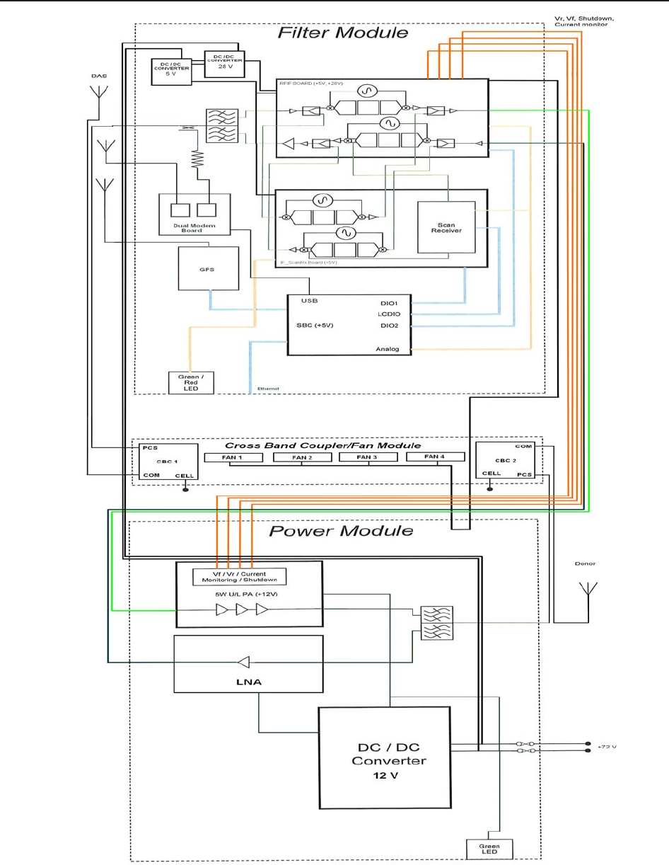
This CSI repeater system is comprised of three modules and the cable assemblies
that interconnect them.
The Filter Module provides frequency selection and filtering. It also houses the
system computer. The Power Module provides amplification and power distribution. The
CBC/Fan Module (Cross Band Coupler/Fan Module) is the interface between the train’s
existing Cellular repeater system and this PCS repeater.
- 5 -
Hardware Configuration
Block Diagram of the Major Components
Section 1
-6 -
Hardware Configuration
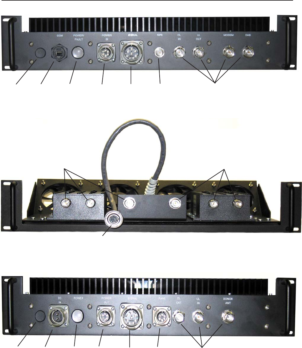
Module Face Plate Configuration
Section 1
Filter Module
One Way
Vent
RJ45
CONN
POWER/
FAULT LED
6 PIN DC
CONN
8 PIN DC
CONN
TNC RF
CONN
Power Module
One Way
Vent
2 PIN DC
CONN
POWER
LED
6 PIN DC
CONN
8 PIN DC
CONN
6 PIN DC
CONN
N TYPE
FEMALE
RF CONN
CBC/Fan Module
N TYPE
FEMALE
RF CONN
N TYPE
FEMALE
RF CONN
6 PIN DC
CONN
- 7-
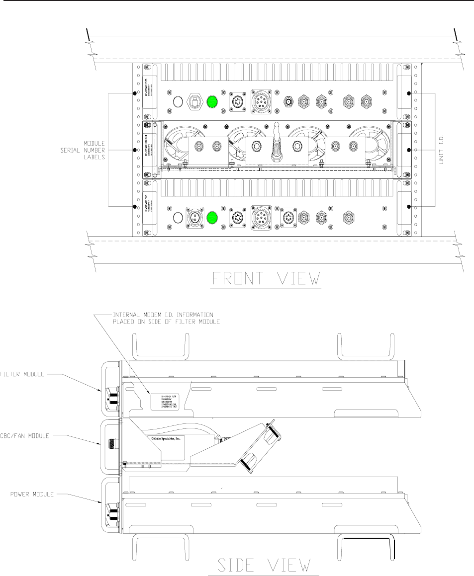
Section 1
Module Label Locations
Hardware Configuration
DASMODEMUL
OUTIN
DLGPSSIGNAL
POWER
IN
FAULT
POWER/
COM
A
B
C
D
E
FH
A
F C
GB
E D
DC
IN
POWER
OUT
POWER SIGNAL FANS DL
OUT
UL
IN
DONOR
ANT
F
E
DC
B
AA
B
C
D
E
F
DE
B
G
C
F
A
H
16-11
VEAM 0
A
B
COMMON COMMON
FHS-632-8 FHS-632-8
Model #:
Serial #:
Item #:
www.cellularspecialties.comwww.cellularspecialties.com
Item #:
Serial #:
Model #: Model #:
Serial #:
Item #:
www.cellularspecialties.com
ESN #:
Item #:
Serial #:
Model #:
www.cellularspecialties.com
C
1
B
1
A
1
- 8 -
Installation
Section 2
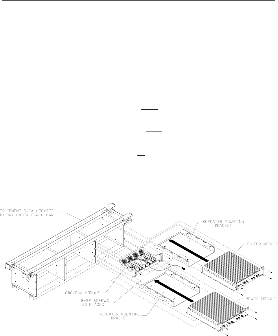
Physical Installation Into The Train
1. Unpack each of the three boxes that make up the CSI repeater system for the
Acela train. The first box contains the Filter Module and associated components.
The second box contains the Power Module and associated components.
Lastly, the third box contains the CBC/Fan Module and associated components.
2. After unpacking, the major components should include one Filter Module, one
Power Module, one CBC/Fan Module and two Repeater Mounting Brackets.
The minor components are 20 #8-32 Phillips Head Machine Screws and cabling for
interconnection of the modules, which will be detailed on the next page. If any parts
are discovered to be missing contact Cellular Specialties, Inc. at 1-877-844-4274 to
arrange for replacements to be sent.
3. Install the Repeater Mounting Brackets, one in the rack’s bottom slot and one
in the rack’s top slot using 4 #8-32 Phillips Head Machine Screws for each.
4. Install the Power Module in the rack’s bottom slot as shown and secure with
4 #8-32 Phillips Head Machine Screws.
5. Install the CBC/Fan Module in the rack’s middle slot as shown and secure with
4 #8-32 Phillips Head Machine Screws.
6. Install the Filter Module in the rack’s top slot as shown and secure with
4 #8-32 Phillips Head Machine Screws.

- 9 -
RF and Power Cabling
Installation
Section 2
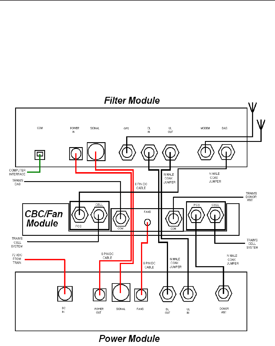
1. With each of the three modules in place, DC and RF cables can be installed. Locate the DC cable with a 6 pin
bayonet type connector at each end (DC1) and connect one end from the POWER IN port on the Filter Module to the
POWER OUT port of the Power Module. Twist each connector clockwise until locked.
2. Locate the DC cable with an 8 pin bayonet type connector at each end (DC2) and connect one end from the
SIGNAL port on the Filter Module to the SIGNAL port of the Power Module. Twist each connector clockwise until
locked.
3. Connect the DC pigtail (DC3) from the CBC/Fan Module to the port labeled FANS on the Power Module. Twist the
connector clockwise until locked.
4. Locate two 1’ N male to N male coax jumpers (RF2 & RF3). One is installed from the DL IN port on the Filter Module
to the DL OUT port on the Power Module. The other jumper connects between the UL OUT port on the Filter Module
to the UL IN port on the POWER Module. Note: hand tighten only. Do not use tools to tighten ANY N type
connectors as damage to the jumper and/or equipment may occur.
5. The next N male to N male coax jumper (RF4) is installed from the DAS port on the Filter Module to the PCS port on
the right side cross band coupler in the CBC/Fan Module. The final coax jumper (RF1) is connected from the port
labelled DONOR ANT on the Power Module to the PCS port on the left side cross band coupler in the CBC/Fan Module.
6. Connect the GPS antenna lead to the port on the Filter Module labelled GPS.
7. Connect the Modem antenna to the port on the Filter Module labelled MODEM.
8. Connect the Train’s donor antenna lead to the COM port on the left side cross band coupler in the CBC/Fan Module.
9. Connect the lead from the train’s cellular system donor port to the CELL port on the left side cross band coupler in
the CBC/Fan Module.
10. Connect the lead to the train’s cellular system’s DAS port to the CELL port on the right side cross band coupler in
the CBC/Fan Module.
11. Connect the Train’s DAS antenna lead to the COM port on the right side cross band coupler in the CBC/Fan Module.
12. The final connection is to the train’s 72VDC power supply. Locate the 2 pin power supply cable and plug it into the
2 pin bayonet type connector on the Power Module labelled DC IN. Twist the connector clockwise until locked.

Coax with N
Connector from
Train’s Donor
Antenna
Coax with N
Connector from
The Donor Side
of the Train’s Cell
Repeater
Train’s 72 Volt
DC Power Cable
With 2 Pin Bayonet
Connector DC1 - 6 Pin Bayonet
to 6 Pin Bayonet
DC Cable Assembly
DC2 - 8 Pin Bayonet
to 8 Pin Bayonet
DC Cable Assembly
Auxiliary Modem
Antenna
Coax with TNC
Connector from
Train’s GPS
Antenna
Coax with N
Connector to
The Train’s DAS
Coax with N
Connector to
The DAS Side
of the Train’s Cell
Repeater
DC3 - Fan Pigtail with
6 Pin Bayonet
Connector
RF2 - 1' N Male to N Male
Coax Jumper RF3 - 1' N Male to N Male
Coax Jumper RF1 - 1' N male Right Angle
to N male Right Angle
Coax Jumper
RF4 - 1' N Male to N Male
Coax Jumper
CAT-5E with RJ45
Connector to
Provide Computer
Interface with the
Repeater
Section 2
- 10 -
RF and Power Cabling
Note: located on the left side of the Filter Module is a standard RJ45 connector port designed to accept CAT-5E
cable, the connector is labelled COM. This port is used to provide a computer interface. Refer to the diagram
below for a graphical representation of the connections described on the previous page.
Installation

-11 -
Section 2
Installation
Power Up
To power up the CSI repeater simply connect the 72 VDC power cable from the train to the DC IN port on the Power Module.
When powered up, the repeater will begin in the Operational Mode, using the “Band Switching Algorithm”. The repeater will not
key until boot up is complete, a GPS location fix is obtained and the unit is within an ” Area Definition”.
Powerup and System Check Out Procedures
Normal Operation
After boot up and a GPS position fix is obtain the repeater will begin operation based on the Area Definitions, “Channel
Power Measurement and Keying Decision” and “Low Isolation Detection and Protection” algorithms. The operational software
will continuously monitor the repeater’s environment and make the necessary adjustments to keep the product operating
within specifications and FCC Type Certification.
System Status
The Software provides real time status data reporting the state of the repeater. This status contains:
Timestamp Modem Band Type Satellite Count
System Up Time Active Filer NoBox Count
Software Version In-band input Searching Count
System Serial Number Measured Output Scan RX Run State
Model Number Composite Input DeKey Limit
Item Number AGC Mode Scan RX Filter ID
Location AGC Attenuation # of Channels
Modem Signal Strength GPS RunState 1 -10 Channel Freq’s & SSI
Modem Registration Status Latitude
Modem Phone Number Longitude RF Alarms: System Alarms:
Modem Current Band Filter ID Over Range Synthesizer Lock
Modem System ID Filter Name Oscillation Voltage
Modem Network ID Location VSWR Temperature
Modem Temperature BTA Out of Band Overdrive Software
Low Signal Hardware
No Signal
Alarms
The Operating Software will monitor the repeater for conditions that are out of normal operation, triggering an alarm
event. The Operating software in conjunction with the Communications Subsystem when so configured will send
alarm messages via E-mail or SMS texting to a User Provisioned account.
Each Alarm has these User Provisioned Capabilities.:
· Disable the System: The Operating software can disable the System (prohibit Keying) until the alarm
condition is cleared if provisioned
· Alarm Filter Conditions: A Filter Condition (such as X number of occurrences per hour) to the alarm to
prevent false or un-useful notifications if provisioned.
· Send an Alarm Message: The Operating Software can send a notification via message E-mail or SMS
through the Communications Subsystem if provisioned.
· Alarm Clear Message: The Operating Software can send an alarm clear message when an alarm
condition clears if provisioned.
Alarm Notification Message
The alarm messages consists of the Systems Identification Tag, a summary of the current alarms, and a short
English message describing the alarm condition(s). Below is a list of the alarms that will trigger an alarm message
to be sent.:
Downlink Over Range Downlink High Temperature Scan Receiver Low Uncalibration
Uplink Over Range Downlink Low Temperature Scan Receiver High AGC Disabled
Synthesizer Error Uplink High VSWR No GPS Data Property File Error
DAC Error Uplink Low VSWR No GPS Lock DAS Failure
DC Current High Uplink Filter Load No GPS Fix Watchdog Timer
DC Current Low Uplink Over Current GPS Antenna Current Modem Not Responding
Downlink High VSWR Uplink Under Current GPS Fix Filter Not Present User Login
Downlink Low VSWR Oscillation Chassis Overheat Password Changed
Downlink Filter Load Uplink High Temperature Chassis Under Temp CPU Boot
Downlink Over Current Uplink Low Temperature Software Abort Placed in Disabled Condition
Downlink Under Current Fan Failure Software Error In Maintenance Mode

-12-
Section 3
Hardware Operations
Test Point Locations and Values
Indicator Lights
The CSI repeater, CS12-553-401, by design, has no external test points. The Power and Filter modules are
sealed with no user serviceable parts inside. The CBC/FAN Module had no user serviceable parts, if fans
are observed to fail the module can be sent back to CSI for evaluation. Testing and configuration is done
exclusively by interfacing the repeater with a laptop or desktop computer and using the Web based GUI or
the TMI. Both user interfaces will provide a complete status of the repeater. In most cases if all other
components of the system prove to be working properly and the repeater is not, the user will need to
return the unit to CSI for inspection and repair. See the Warranty and Repair Procedures in Section 3 of
this manual.
If the covers for the Power and or Filter modules are removed by the user the warranty will be void and
the cost of any needed repair will be the responsibility of the user.
This repeater was designed with only two external indicator lights. Both are approximately 3/4”
diameter LEDs. Located on the Filter Module face plate, between the COM and POWER IN ports, the first
LED labeled POWER/FAULT glows red as the repeater is powered up. When the unit completes all of
it’s bootup procedures the LED will change color and glow green to indicate the system is operating
normally. If the LED remains red it’s an indication of a problem and the user will need to check the
system status using the Web based GUI or the TMI.
The second LED is located on the faceplate of the Power Module, between the DC IN and POWER OUT
connector ports. This light is designed only to show that the unit has DC current and will glow green
when the unit is powered.
Troubleshooting
All cables should be checked for shorts and opens.
The rooftop antenna (Donor Antenna), should be checked for damage.
The DAS antennas should be checked for damage.
If cables and antennas are acceptable and the problem persists, check repeater status using the Web
based GUI or the TMI. See Alarm/Action Matrix on the next page.
Should the repeater fail, or if service is lost and the cause can not be determined from the steps above, the user
should contact CSI Technical Support @ 1.877.844.4274. CSI will remotely access the repeater and advise the
respondent of next step(s).

- 13 -
Hardware Operations Section 3
Subsystem Alarm Name Alarm Send Shutdown Disable
Type E-mail Op Mode? Unit?
Downlink Power Over Range Critical Yes Yes No
Low Signal Routine No No No
No Signal Routine No No No
Out of Band Signal Routine No No No
Uplink Power Over Range Critical Yes Yes No
Out of Band Signal Routine No No No
Common Hardware Alarms Synthesizer Error Critical Yes Yes Yes
Dac Error Critical Yes Yes Yes
DC Current High Severe Yes Yes No
DC Current Low Severe Yes Yes No
Downlink PA Oscillation Routine No No No
Input Power High Routine No No No
High VSWR Severe Yes No No
Low VSWR Severe Yes No No
FilterLoad Critical Yes Yes No
Overcurrent Severe Yes No No
Undercurrent Severe Yes No No
Low Isolation Routine No No No
High Temperature Severe Yes Yes No
Low Temperature Severe Yes No No
Uplink PA HighVSWR Severe Yes No No
Low VSWR Severe Yes No No
FilterLoad Critical Yes Yes No
Overcurrent Severe Yes No No
Undercurrent Severe Yes No No
Oscillation Routine No No No
Low Isolation Routine No No No
High Temperature Severe Yes Yes No
Low Temperature Severe Yes No No
Fan Activation Routine No No No
Fan Failure Severe Yes No No
Scanning Receiver Alarms ScanRcvrLow Severe Yes Yes No
ScanRcvrHigh Severe Yes Yes No
GPS Receiver Alarms No GPS Data Critical Yes Yes Yes
No GPS Lock Severe Yes No No
No GSP Fix Critical Yes Yes No
Gps Antenna Current Severe Yes No No
Gps Fix Filter Not Present Severe Yes Yes Yes
Software Alarm Types Overheat Severe Yes No No
Undertemp Severe Yes No No
Software Abort Critical Yes Yes ??
Software Error Severe Yes Yes No
Uncalibration Critical Yes Yes Yes
Agc Disabled Critical Yes Yes Yes
Property File Error Critical Yes Yes No
Das Failure Critical Yes Yes No
Watchdog Timer Critical Yes Yes No
Heartbeat Informational No Yes No
Communications Modem Not Responding Severe Yes No No
Modem Not Connected Routine No No No

-14 -
Hardware Operations
Section 3
Warranty and Repair Procedures
1 Scope
The warranty period for this product shall be 18 months (548 calendar days)
from the date of the Purchaser’s Acceptance, plus any extended mainte-
nance periods as specified in the order. During said period(s), CSI warrants
that each repeater will be free of defects in material and workmanship.
CSI’s sole obligation and the Purchaser’s exclusive remedy for any breach
of warranty is limited to adjustments, repairs, or at the Purchaser’s option,
replacement of a System or parts of a System thereof at no cost to the CSI.
All exchanged Systems or System parts will become the property of the
CSI. Servicing hereunder will be furnished by the CSI’s nearest service
location. CSI shall perform this service at a time agreed to by the Pur-
chaser. This warranty will not apply to a particular item if:
(a) Adjustment, repair or replacement is required because of accident,
neglect, misuse, failure of electric power, environmental controls, transporta-
tion or causes other than ordinary use, except that such adjustment, repair,
or replacement is required due to actions caused by or the responsibility of
CSI’s employees or CSI’s authorized agents;
(b) The Purchaser fails to operate a System or follow operator-level mainte-
nance procedures in accordance with the CSI’s recommendations;
(c) Any person other than the CSI’s engineer or an authorized agent of the
CSI modifies, adjusts, or repairs the product or performs any maintenance
service other than routine operator-level maintenance without the CSI’s prior
written consent.
The warranty hereunder does not include:
(a) Any furnished consumable supplies,
(b) Painting or refinishing the product,
(c) Electrical work external to the product,
(d) Installation, maintenance or removal of alterations or attachments to the
product except as provided by the original system design.
CSI’s liability for breach of the above warranty will in no event exceed the
purchase price of the Product(s) that has been paid by the Purchaser.

- 15 -
Hardware Operations
Section 3
2 Product Hardware Warranty (Non-Software)
(a) CSI represents and warrants to the Purchaser that upon delivery of a repeater to
the Purchaser, all right, title and interest in the unit will pass to the Purchaser free of
all liens, imperfections in title, claims, charges, restrictions, or other encumbrances.
The CSI represents and warrants a repeater’s Hardware (specifically excluding the
Product Software) as furnished shall be new, merchantable, free from defects in
material and workmanship, fit for the ordinary purpose for which the product is used,
shall not infringe on any U.S. Patent, and for the period specified in this document
from the date a repeater is delivered and shall conform to this documents specifica-
tions. Should a unit not conform to the foregoing warranties, CSI shall repair or
replace defective or nonconforming product.
(b) During the warranty period, a defective repeater shall be either repaired on-site
by the CSI or returned to the CSI for repair or replacement at no charge or cost to
the Purchaser. The Purchaser shall bear the risk of loss or damage until a unit is
placed in the possession of the carrier. Unless otherwise agreed to by the CSI and
the Purchaser, for a product that is returned to the CSI for repair, CSI shall complete
repairs and return repaired the product, or ship a replacement product, within three
(3) days of receipt of defective repeater at CSI’s designated repair location. CSI
shall bear the cost of transportation charges for shipment to CSI (FOB origin freight
collect) of the product to be repaired or replaced. For return shipments from CSI to
the Purchaser, CSI shall bear the risk of loss or damage during transit and shall
prepay and bear the cost of transportation charges for shipment of the product that
has been repaired or replaced. If a repeater returned is not defective, CSI shall
promptly advise the Purchaser in writing of the determination and in such cases,
CSI shall return product to the Purchaser at the Purchaser’s expense and risk in its
“as received” condition. If a repeater is returned and is not in warranty, CSI shall
promptly advise the Purchaser in writing of this determination and the charge to
repair the product. In such cases, CSI shall repair the product if so instructed by
the Purchaser in writing and charge the Purchaser for labor, parts, and shipping.
(c) During the warranty period, if the Purchaser’s technical personnel attempt to
determine whether or not a CSI repeater is the cause of service interruption and
cannot identify and resolve the problem causing the interruption after communicating
with CSI’s technical personnel via telephone or other suitable means, and the
service interruption still exists, then the Purchaser may request that CSI begin on-
site repairs as soon as possible, but in no event later than one (1) business day
plus reasonable travel time after receiving the Purchaser’s request. If the problem is
with CSI’s product, (software or hardware), such on-site repairs by CSI shall be at
no charge to the Purchaser.
Warranty and Repair Procedures

-16 -
(d) During the Warranty period, if the service interruption still exists after compliance
with (c) above, and the service interruption is caused by either CSI’s defective repeater(s)
and/or CSI’s product that does not confirm to specification and the CSI has been given a
reasonable time frame, as determined by the Purchaser, to correct the service interrup-
tion, the Purchaser may return the product to CSI and receive a credit for the total
purchase price of the Product or a completely new repeater, at the Purchaser’s option,.
(e) Any replacement, repair, modification, installation or other service performed by CSI
shall be warranted, commencing with the date upon which repaired product is returned to
the Purchaser, for the remainder of the unexpired period of the warranty.
(f) The warranties do not extend to a repeater to the extent that such repeater has been
subjected to misuse, neglect, abuse, accident caused by the Purchaser or by a third
party subsequent to the delivery of the unit, and such action is the cause of the damage
or malfunction.
Hardware Operations
Section 3
Warranty and Repair Procedures
3 Product Software Warranty
(a) CSI warrants that the Purchaser shall have quiet enjoyment of the Product Software
and that the Product Software and the Purchaser’s use shall be free from claims of infringe-
ment, misuse or misappropriation of any intellectual property right during the term of the
Purchaser license to Use the Software. As to Product Software which the CSI does not
have title, CSI warrants that has rights in the Software sufficient to permit the license of the
Software to and that CSI has full right, power and authority to license the Software and
other rights granted hereunder to Verizon Wireless.
(b) CSI also warrants that the media containing the Software will be free from defects in
material and workmanship and that all related services provided by CSI shall be rendered by
qualified personnel who will perform the tasks assigned consistent with good professional
practice and the state of the art involved.
(c) CSI also warrants that there does not exists an copy protection or similar mechanisms
within the Product Software, which will, either now or in the future, interfere with the opera-
tion of the Product. Furthermore, CSI warrants unless requested in writing by the Purchaser
and the Purchaser approves response, or CSI advises the Purchaser in writing that it is
necessary to perform valid duties under this attachment and authorized in writing by the
Purchaser, any Product Software provided to the Purchaser by CSI for Use by the CSI or the
Purchaser shall:

- 17 -
Hardware Operations
Section 3
Warranty and Repair Procedures
· contain no hidden files;
· not replicate, transmit or activate itself without control of an of an authorized
person operating computer equipment on which it resides;
· not alter, damage or erase any data or computer programs without control of an
authorized person operating computer equipment on which it resides;
· contain no encrypted imbedded key, node lock, time-out or other function,
whether implemented by electronic, mechanical or other means, which restricts or
may restrict Use or access to any programs or data developed under this Agree-
ment, based on residency on a specific hardware configuration, frequency of
duration of Use, or other limiting criteria (“Illicit Code”).
(d) Where the Product Software is intended to be used in transaction processing or in
the public switched network, CSI represents that nothing in the Product Software
precludes the Purchaser form integrating a network management solution (including
transaction processing and network monitoring) with the Product Software.
(e) For the period specified beginning with the effective date of license of the Soft-
ware, CSI represents and warrants that the Product Software will perform in accor-
dance with specifications. If within one year (365 days) subsequent to the expiration
of the warranty period CSI has not repaired the Product Software to perform in accor-
dance with specification for any exception communicated in writing by the Purchaser
to CSI during the warranty period, the Purchaser may order and CSI shall refund to
the Purchaser the amount paid to it for the nonconforming Product Software.
(f) CSI represents and warrants that if any portion of the Product Software is or
becomes unusable, totally or in any respect, the Supplier will correct errors, defects
and nonconformity and restore the Product Software to conforming condition without
additional charge to the Purchaser.

-18 -
4 Continuing Availability of Service and Parts
(a) CSI shall, if requested by the Purchaser, provide the Purchaser with
maintenance service, repair service and parts for the Product and Soft-
ware, for a period of seven (7) years after extended Product and Service
agreements have been discontinued by the Purchaser. If CSI is unable to
supply such services and/or parts or CSI is unable to obtain an alternative
source to provide such services and/or parts for the Purchaser, then the
CSI shall, without obligation or charge to the Purchaser, provide the
Purchaser with drawings or other documents required to either manufac-
ture or buy such parts and the technical information or any other rights
necessary for the Purchaser to manufacture or purchase such parts for
the purpose of supporting the Purchaser’s customer base.
(b) The technical information shall include, by example and not by way of
limitation:
· Manufacturing drawings and specifications of materials and parts
comprising the replacement and repair parts and components;
· Manufacturing drawings and specifications covering special tooling
and operation;
· A detailed list of all commercially available Continuing Availability of
Service and Partsble parts and components purchased by CSI on the
open market, disclosing the part number, name and location of the
Company and price lists for the purchase; and
· One complete copy of the source code used in the preparation of any
software licensed or otherwise acquired by the Purchaser from CSI,
provided however, that such source code shall remain the property of
CSI and shall be separately licensed to the Purchaser for use by the
Purchaser to support the Product.
(c) In the event that CSI either (i) does not own the source code or (ii)
does not have the rights to disclose such source code, then CSI shall
disclose its licensor or owner of said source code and shall get the rights
on behalf of the Purchaser.
(d) Certain parts of the Product Software is subject to a licensing agree-
ment and is sublicensed to the Purchaser. In the event of the inability to
provide updates or continuing support of the application software at a
reasonable cost, CSI shall assist the Purchaser in locating an alternative
source.
Hardware Operations
Section 3
Warranty and Repair Procedures
5 Product Returns
Please call 1.877.844.4274 to obtain a Return Material Authorization (RMA)
number for product assessment and repair.
-19 -
Software Operations
Section 4
General Operation Overview
Web based GUI Session
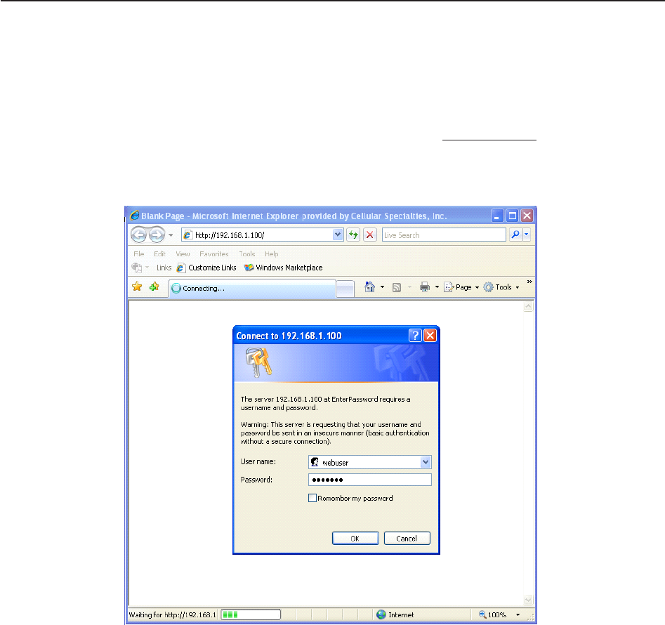
Primary access to the repeater is gained using a LAN connection and a web browser program such as Firefox by
Mozilla, or Internet Explorer from Microsoft. The repeater ships in DHCP server mode and by default the IP address will
be 192.168.1.100. *
If connecting directly to the repeater from a laptop or PC with a crossover CAT-5E cable or over a LAN the user types
the IP address of the repeater into the browser address line to connect. When connection is made the user will be
prompted for a user name and password. For the purpose of the GUI session, the default user name is webuser and
the password is csi1234. This can also be changed as required. Internet access is not required to use the GUI. (Note:
If you are connecting using a laptop, verify that your Ethernet port is powered. Some laptops will not allow Ethernet
connection when on battery power. If this is the case with the laptop you are using you will need to plug it in or update
the power settings.)
*DHCP is a protocol that allows computers on a network to be automatically configured appropriately for that network.
Networks provide DHCP service by maintaining one or more servers that listen for special broadcasts on the network,
called DHCP requests. These requests are made by computers when they first join a particular network. The DHCP
server replies with configuration information that the requester uses to join the network.
In the case of this repeater, the unit is configured to act as a DHCP server by default. This means that a computer
configured to make a DHCP request on joining a network (most laptops are set up this way) will automatically receive a
configuration from the repeater when it is connected to it via the local network port. This connection is made with either
a crossover cable or an Ethernet switch or hub.
One word of caution: The repeater, if it joins a network already managed by another DHCP server, may cause
disruptions in that network. To avoid any such problems, reconfigure the unit for static or DHCP client mode before
connecting it to such a network. (The local networking config page in the web interface, and the menu interface, can
be used to achieve this.)
- 20 -
Software Operations
Section 4
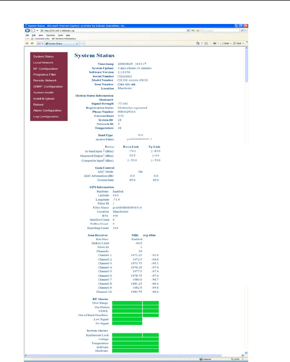
When login is complete the user is brought to the system status page. The links on the page are activated by clicking on
them.
System Status:
General Operation Overview
- 21 -
Software Operations
Section 4
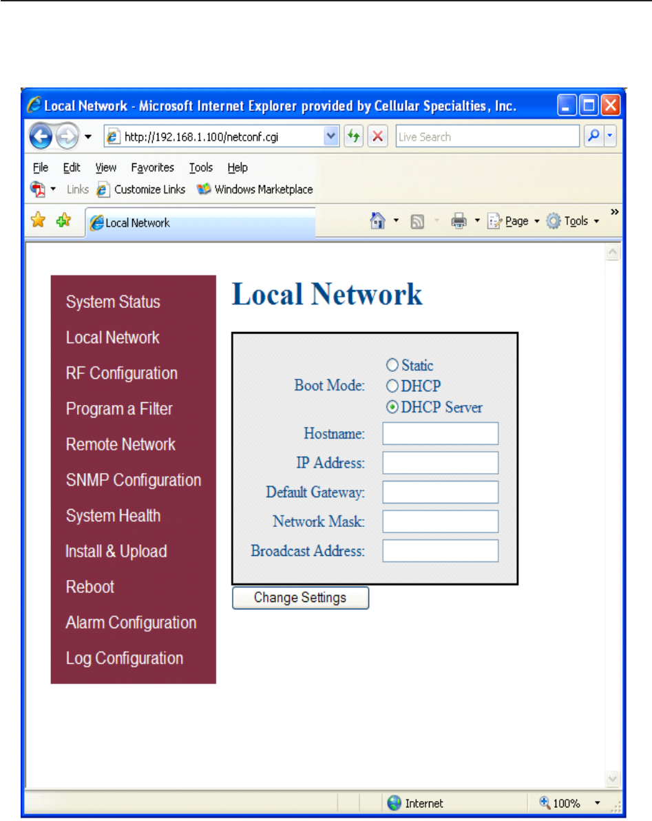
If the user selects Local Network from the System Status page, the following screen is displayed and from here network
configuration can be modified as required. The default is set to DHCP Server. It is recommended you check with your IT depart-
ment for explanation of the options and approval before you connect this repeater to your network or change the options.
Local Network:
General Operation Overview
- 22 -
Software Operations
Section 4
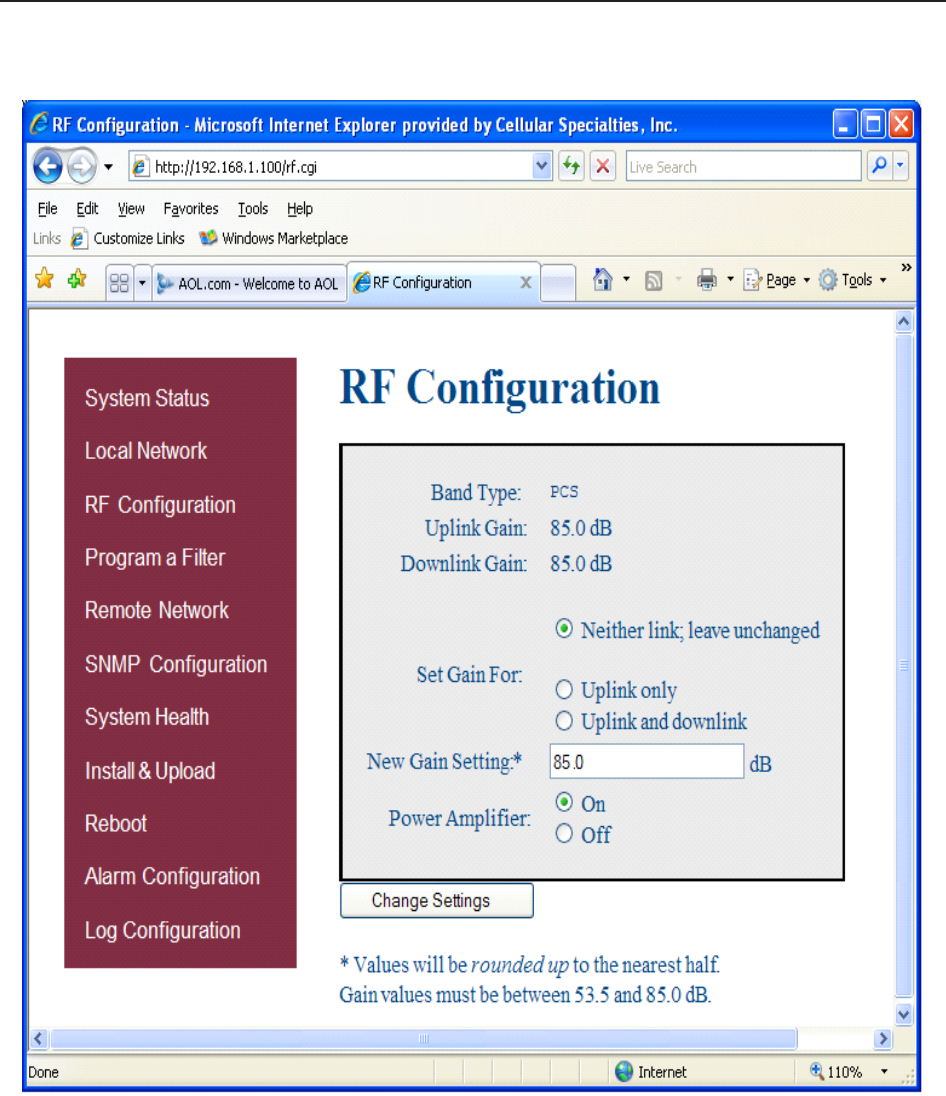
From here the user may return to the System Status screen or click on the other options. If the user would like to modify RF
configuration click on the words RF Configuration in the brown navigation box and the screen below is displayed.
RF Configuration:
To change gain settings the user will select the Uplink only or Uplink and Downlink radio buttons. The user then inputs the
gain value desired. Gain values from 53.5 dB to 85.0 dB may be selected. The repeater will not allow the user to set
values outside this range. By pressing the Change Settings button the gain change is implemented. When a new filter set
is required, it may be selected by clicking Program a Filter in the navigation box.
General Operation Overview
- 23 -
Software Operations
Section 4
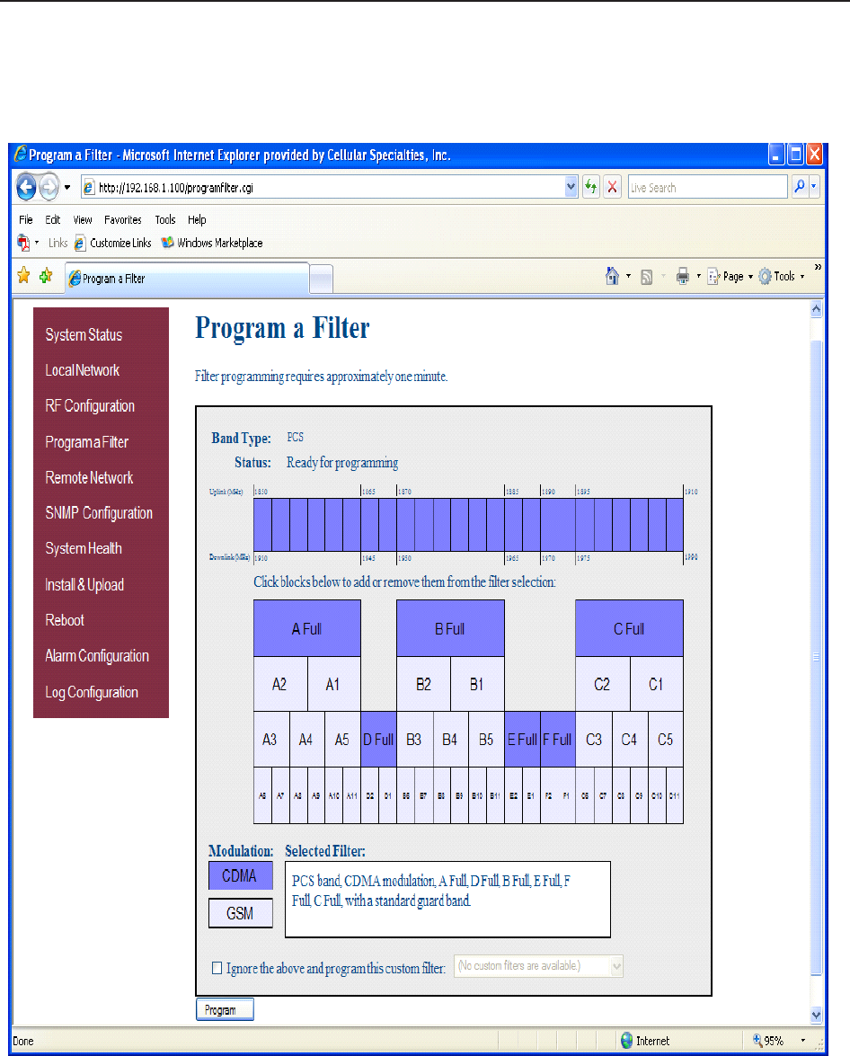
The user may select the desired filter by pressing the band/sub-band and modulation selection buttons. Undesired bands/sub-
bands if lit will require the user to manually “deselect” them before programming. Pressing the Program button will complete
the selection and load the desired filter. The time required to complete this process will take just a few moments. Note: If the
filter desired is not currently in the unit, additional filters along with instructions on how to load them are available by contact-
ing CSI.
Program a Filter:
General Operation Overview
- 24 -
Software Operations
Section 4
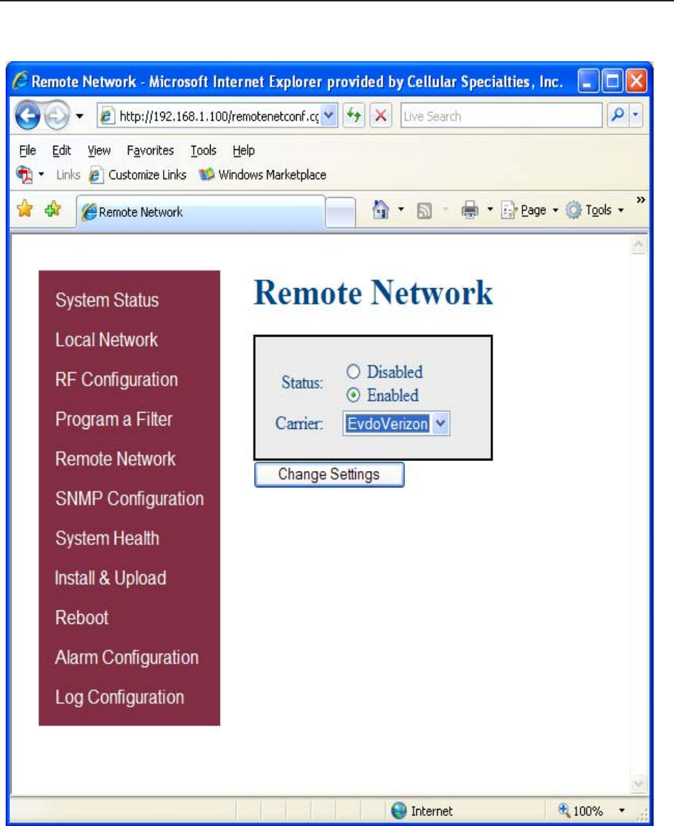
Highlight the carrier on whose network the repeater and modem will be configured and click the Change Settings button. Note:
the system will require restart for the change to take effect.
Remote Network:
General Operation Overview
-25 -
Software Operations
Section 4
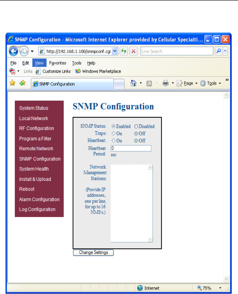
To change SNMP settings click SNMP Configuration in the navigation box, the screen below will be displayed. If the user is not
well versed in Simple Network Management Protocol he or she should check with their IT professional for proper setting
requirements.
SNMP Configuration:
General Operation Overview
- 26 -
Software Operations
Section 4
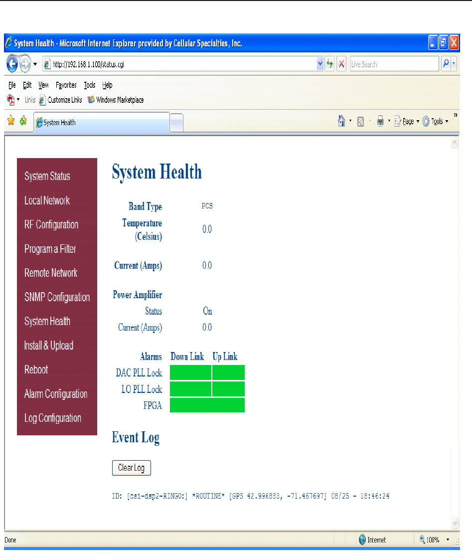
By clicking System Health the current state of the repeater can be reviewed.
***The user may clear alarms and the Event Log by clicking the Clear Log button.
System Health:
***
General Operation Overview
-27 -
Software Operations
Section 4
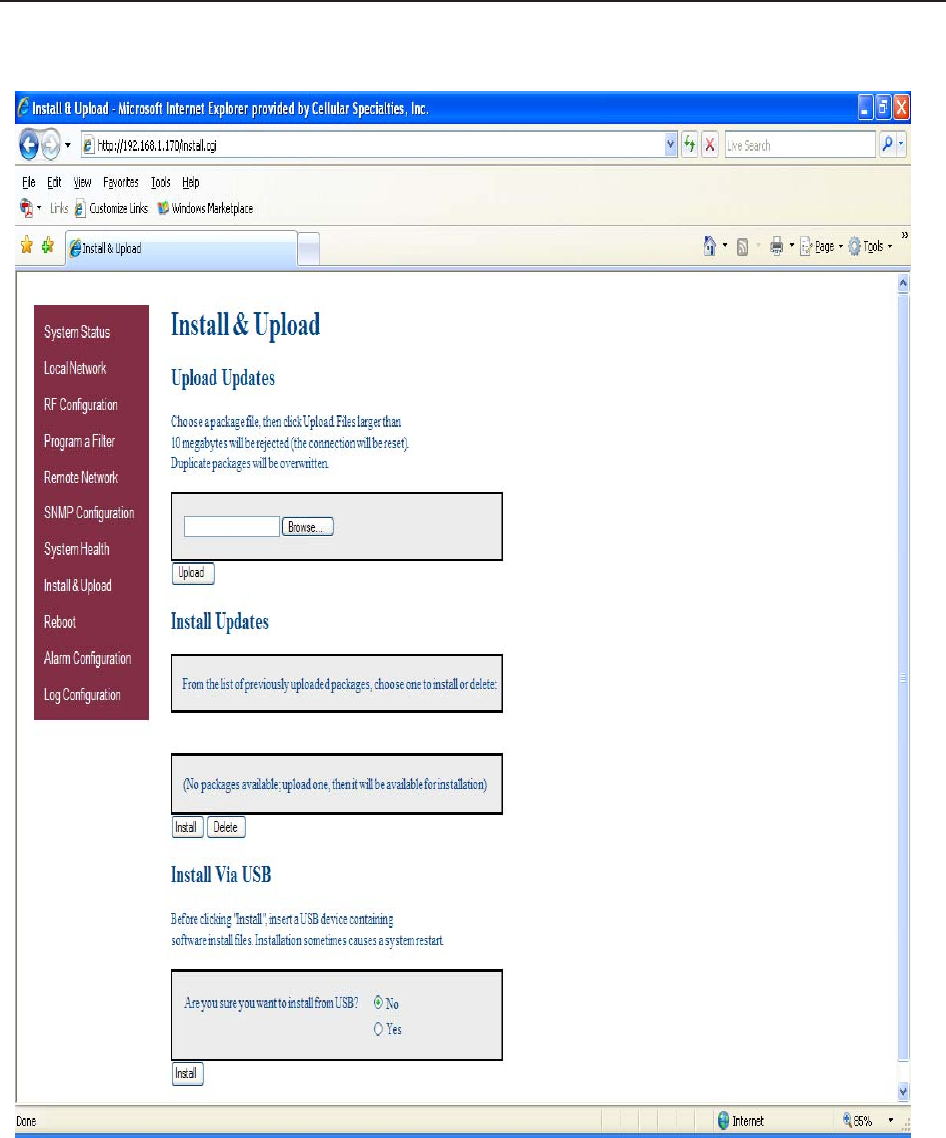
Should a software install or upgrade be needed it can be done from the Install & Upload screen shown below. As with the other
screens it can be reached by clicking the words in the navigation box.
Install & Upload:
General Operation Overview
-28 -
Software Operations
Section 4
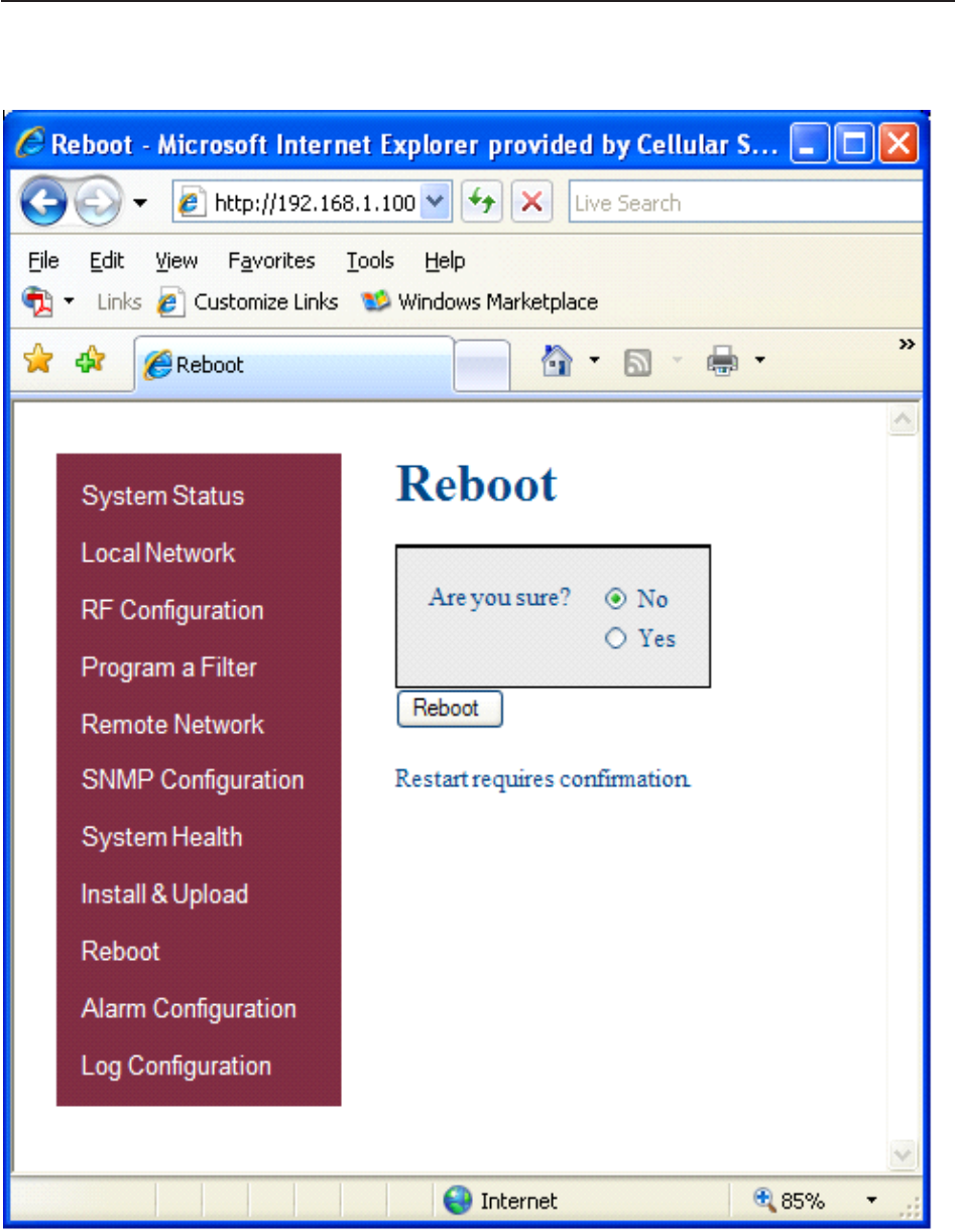
If a reboot of the repeater becomes necessary click on the Reboot option in the navigation box and the Reboot page is
displayed.
Reboot:
General Operation Overview

- 29 -
Software Operations
Section 4
In order to review and configure the system’s alarms click on the Alarm Configuration line in the navigation box and page
shown below is displayed.
Alarm Configuration:
General Operation Overview
- 30 -
Software Operations
Section 4
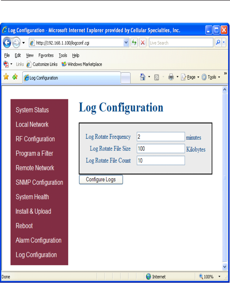
In order to review and update the system’s log configuration, click on the Log Configuration line in the navigation box and page
shown below is displayed.
Log Configuration:
General Operation Overview
- 31 -
Software Operations
Section 4
Text Menu Interface:
A Text Menu Interface (TMI) is provided as an alternate means of access and control of the repeater. To use the TMI, also known as
the console interface, connect a CAT -5E cable to the RJ45 connector port labeled COM and a computer making use of a standard
terminal emulation program.
Many terminal emulation programs will work if properly configured. In the following description, “TeraTerm” is used to establish the
TMI session. This program is readily available via the Internet and is free from Ayera Technologies at:
http://www.ayera.com/teraterm/
TeraTerm Pro Web works on Windows 95/98, 2000, XP. Here is the latest TeraTerm Pro Web release:
Version 3.1.3, October 8, 2002. ttpro313.zip
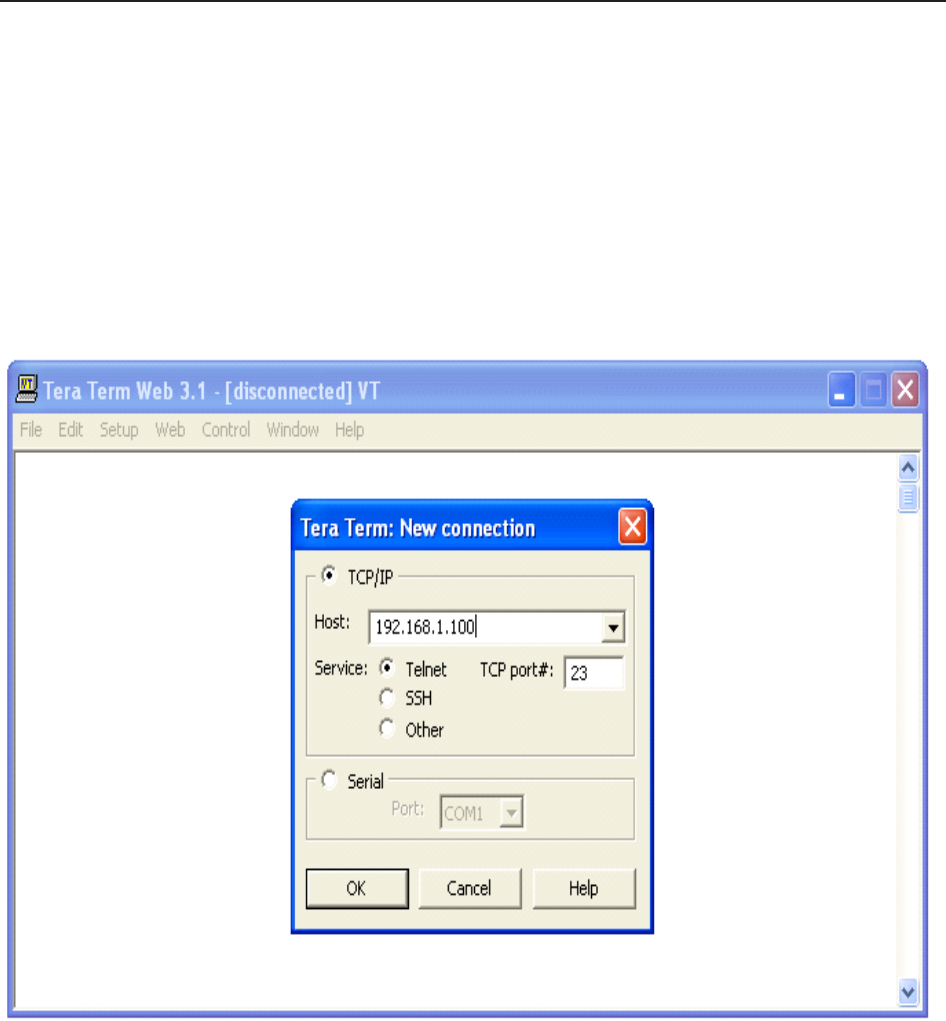
When the program is started, the following screen is displayed.
In the box labeled Host type the repeaters IP address and click OK. The user will then be prompted for a user name and
password. The default user name is “user” and the password “csi1234”. After entering the password and pressing return
the TMI main menu will appear.
General Operation Overview

- 32 -
Software Operations Section 4
General Operation Overview
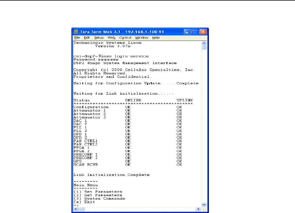
Upon logging the user is presented with a summary of the initialization status. The data represents a top level list of the major
components that must be operating properly in order to have a function system. The display will “block” until a particular
component is finished being initialized.
Status DNLINK UPLINK
============================================
Configuration OK OK
Attenuator 1 OK OK
Attenuator 2 OK OK
Attenuator 3 OK OK
DAC 1 OK OK
DAC 2 OK OK
PLL 1 OK OK
PLL 2 OK OK
DPD 1 OK OK
DPD 2 OK OK
FAN CTRL1 OK OK
FAN CTRL2 OK OK
FPGA 1 OK OK
FPGA 2 OK OK
PRECOMP 1 OK OK
PRECOMP 2 OK OK
GPS OK OK
SCAN RCVR OK OK
Link Initialization Complete
Once the initialization sequence is complete, the user is presented a top level menu used to access all of the systems
operating parameters. The top level menu is organized into three main sections, settable parameters, status parameters, and
system functions.
=========
Main Menu
=========
(1) Set Parameters - Disabled
(2) Get Parameters
(3) System Commands
(x) Exit
->
The “Set Parameters” menu is password protected (user definable) in order to prevent erroneous configurations being made
by non-qualified users. The user will be prompted to enter the correct login and password on a per-session basis. Once the
user has entered the correct values, subsequent access is not inhibited.
=========================
Set Parameters - Disabled
=========================
(1) Maintenance Mode Login
(r) Return to previous menu
->

- 33 -
Software Operations Section 4
General Operation Overview
——————
Enter Username:csi
Enter Password:csi1234
Maintenance Mode Enabled
========
Main Menu
=========
(1) Set Parameters
(2) Get Parameters
(3) System Commands
(x) Exit
->
==============
Set Parameters
==============
(1) Link Configuration
The “Link Configuration” menu is a collection of menu options that control the RF operating characteristics of a live system.
==================
Link Configuration
==================
(1) Adjust Gain
The “Adjust Gain” option allows the user to control the total gain of the system. Valid gain settings range from 55 dB to 85
db. If the user selects to configure the downlink gain, the uplink gain will automatically be set to the same value. In order
to override this condition, the user will have to select the uplink option and adjust the gain to the desired value.
—————
Links:
(1) downlink
(2) uplink
(r) Return to previous menu
Link?
—————
User Gain:
Setting 85.00 dB
User Gain? 85.0
Auto Setting Uplink Gain to 85.00 dB
To override, set Uplink gain separately
(2) Select Active Filter
The “Select Active filter” option allows the user to toggle between the filters loaded in the RFIF and IF board for test
purposes. Please note that in order for this to work properly, the GPS task needs to be disabled otherwise the filter
selection will be overridden by the current location of the system.

- 34 -
Software Operations Section 4
General Operation Overview
————————
FILTER settings:
(1) select IF board filter
(2) select RFIF board filter
(3) disable both RFIF and IF board filter
(r) Return to previous menu
FILTER settings?
(3) Filter Programming
The “Filter Programming” option allows the user to select and program one of the loaded filters on the system. The user
will be prompted to select which board the filter will be loaded on, RFIF or IF. Please note that in order for this to work
properly, the GPS task needs to be disabled otherwise the filter selection will be overridden by the current location of the
system.
——————
File names:
(1) pcR0A0D0B0E0F0C0-0
(2) pcR0A0D0B0E0F0C0-Wide
(3) pcR1F0C3C4-0
(4) pcR2E0C3-0
(5) pcR3F0-0
(6) pcR4F0C0-0
(7) pcR5E0F0-0
(8) pcR6D0C3C4-0
(9) pcR7F0C3-0
(r) Return to previous menu
Enter file number?
(4) Power Amplifier Output Control
The “Power Amplifier Output Control” option allows the user to control the state of the power amplifier, ON or OFF. The
setting overrides all other PA control tasks and is persistent across reboots. Care must be taken to insure the user is
aware of the state of this setting so as to eliminate false keyed/de-keyed states.
————————
PA Output Enable:
(1) off
(2) on
(r) Return to previous menu
PA Output Enable?
(r) Return to previous menu
->
(2) Alarm Configuration
The “Alarm Configuration” menu is a collection of menu options that control the alarming operating characteristics of a live
system.

- 35 -
Software Operations Section 4
General Operation Overview
===================
Alarm Configuration
===================
(1) Alarm Masking
The “Alarm Masking” option provide the user an ability to mask or unmask individual alarms based on the known
operating characteristics of the environment that the unit is place in. Certain alarms will occur that do not directly
affect the proper operation of the system and can therefore be masked. All alarms are still registered with the
system regardless of the alarm state, user notification only takes placed on unmasked alarms.
=============
Alarm Masking
=============
(1) Show Alarm Configuration
(Displays the current mask state of all the alarms.)
(2) All Alarms
(Sets all alarms to a given mask state (ON/OFF)).
(3) Link Alarms
(Sets specific alarms of a particular link to a given mask state (ON/OFF)).
(4) HW/SW Alarm Configuration
(Sets specific alarms of a specific sub-system to a given mask state (ON/OFF)).
(5) Miscellaneous Alarms
(Sets specific miscellaneous alarms to a given mask state (ON/OFF)).
(r) Return to previous menu
->
(2) Alarm Notification
The “Alarm Notification” option provides the user the ability to configure the system to externally notify service
personnel of alarm event s.
==================
Alarm Notification
==================
(1) Alarm Origin Tag
The “Alarm Origin Tag” option provides user access to two settable parameters that are used to
distinguish which system is reporting the alarm. The user should develop a relative scheme of naming
individual units so that they can be easily identified by service personnel. The two parameters are
included as part of the alarm information that is sent.
================
Alarm Origin Tag
================
(1) Host Name
(2) Location
(r) Return to previous menu

(2) E-mail Alarm Configuration
==========================
E-mail Alarm Configuration
==========================
The “E-mail Alarm Configuration” option configures the e-mail alarm notification sub-system.
(1) Show E-mail Config
(Displays the current configuration of the e-mail subsystem.)
(2) Enable/Disable msmtp
(Controls the state of the e-mail sub-system, the user must first enable msmtp in order for any e-mail
alarms to be sent.)
(3) Set Recipient Address
(This option allows the user to configure up to five destination e-mail addresses that will receive
system alarm events. It is best to leverage the management and configuration options of a destination
mail server in order to setup a mail group of service personnel that will receive the alarms.)
(4) Heart Beat Email Configuration
(The system is capable of being configured to send out a heartbeat e-mail on a periodic basis. This
function can be used to monitor the operational state of the system.)
(5) Send Test Email
(Provided that the e-mail sub-system is enabled and that there are configured destination addresses,
this option will generate a test e-mail for diagnostic purposes.)
(6) E-mail Client Configuration
(This menu item provide access to user configurable options that setup the e-mail client (DSP system)
for use with an authenticated e-mail server and account.)
(r) Return to previous menu
->
(3) SMS Message Configuration
The “SMS Message Configuration” option configures the SMS (Short Messaging Service) l alarm notification
sub-system. This option can be used to send alarm notifications to a user’s cell phone as text messages.
(r) Return to previous menu
->
- 36 -
Software Operations Section 4

- 37 -
Software Operations Section 4
(3) Watchdog Timer Configuration
The “Watchdog Timer Configuration” option configures a hardware based watchdog timer. Once enable, the DSP
software will periodically write to the watchdog timer thus preventing an unscheduled reboot. Certain alarms can
be configured to inhibit this periodic write which in turn will reboot the system when they occur.
============================
Watchdog Timer Configuration
============================
(1) ON
(2) OFF
(3) Reset Reboot Counter
(r) Return to previous menu
->
(r) Return to previous menu
->
(3) Networking Configuration
The “Networking Configuration” menu contains three configuration menus. The “Local Network Configuration” provides access to
the network connection that is made to the system via the Ethernet port located on the front panel of the unit. The “Remote
Network Configuration” is used to configure the wireless modem(s) that are attached to the USB port of the SBC (single board
computer) that controls the unit. The “SNMP Configuration” option is not used or supported in this version of product.
========================
Networking Configuration
========================
(1) Local Network Configuration
The “Local Networking Configuration” menu allows the user to configure the Ethernet port to operate in one of
three modes once enabled. If the unit is configured to have a static IP address, then the user must know what the
characteristics of the network are that the unit will be connected to. In DHCP client mode, the unit will broadcast a
request for an IP address from a properly configured DHCP server on the network. In DHCP server mode (default)
the unit will assign itself an IP address of 192.168.1.100 and it will also listen for DHCP IP address requests. If the
user connects a device (laptop) directly to the Ethernet port (cabling requirements may differ) the unit will issue an
IP address of 192.168.1.90. The unit is currently capable of issuing one client address. This is done to limit
cataclysmic events should the unit be connected to a network that already has a DHCP server.
———————————
CAUTION: Network reconfiguration may cause local and remote access interruptions.
———————————
===========================
Local Network Configuration
===========================
(1) enable
(2) disable
(3) set default static IP (192.168.1.100)
(4) set labview calibration IP (192.168.1.69)
(r) Return to previous menu
->

- 38 -
Software Operations Section 4
(2) Remote Network Configuration
The “Remote Networking Configuration” menu allows the user to configure the modem connected to the
internal USB port of the SBC. This version of software is preconfigured to enable the default modem type
installed in the unit and no user selection is necessary.
============================
Remote Network Configuration
============================
(1) enable modem
(2) disable modem
(3) Set Modem HeartBeat IpAddress
(r) Return to previous menu
->
(3) SNMP Configuration
The “SNMP Configuration” menu is not supported for this revision of the product.
==================
SNMP Configuration
==================
(1) enable SNMP
============================
SNMP Configuration Parameter
============================
(1) Show SNMP Config
(2) List NMS IP Addresses
(3) Clear NMS IP Addresses
(4) Create NMS IP Address List
(5) Heartbeat Control
(6) Heartbeat Frequency
(7) Trap Control
(8) Restart SNMP Daemon
(9) Send Test Trap/Inform
(r) Return to previous menu
->
(2) disable SNMP
(r) Return to previous menu
(r) Return to previous menu
(4) Log File Configuration
The system is capable of storing its log files persistently on a periodic basis so that post mortem analysis can take place. The log
files will be placed in the “/log” directory on the compact flash. The service personnel can then use off the shelf applications to
extract the information to their laptop for review.

- 39 -
Software Operations Section 4
======================
Log File Configuration
======================
(1) Display Log Rotate Settings
(Displays the current settings of the log file rotation parameters.)
(2) Change Log Rotation Period
(This option allows the user to control the frequency of the log rotation task which will persistently store the log
files based on size.)
(3) Change Minimum Log Size
(If a running log file exceeds this size (in bytes) the log file will be copied to the persistent storage location.)
(4) Change Number of Logs Rotated
(This parameter determines the number of log files of each type to maintain in persistent storage. Once the
maximum number is reached, older files are discarded keeping only the most recent files.)
(5) Configure Log to File
(This option allows the user to write the current system status information to the appropriate log file on a periodic
basis.)
(r) Return to previous menu
->
(5) GPS Configuration
The GPS sub-system is an integral part of the control of the DSP based system. During normal operating mode, the GPS
receiver controls the selection of filters and the key state of the unit. The unit must first receive a valid GPS string from the
satellites before the unit will perform properly. The following menu allows the user to examine and configure the GPS
operating parameters of the unit.
=================
GPS Configuration
=================
(1) Set GPS Mode
The GPS mode menu controls the operational state of the GPS receiver. The system is designed to run with a
GPS emulator connected to COM3 (internal) for use s a test/debug mode. Additional menu items can be used to
assist in the diagnosis of GPS related issues.
============
Set GPS Mode
============
(1) Enable GPS Receiver (default enabled)
(2) Enable GPS Emulator (default disabled)
(3) Disable GPS Receiver (default enabled)
(4) Enable/Disable Amplifier (default enabled)
(5) Set No Box Shutdown Mode (default enabled)
(6) Set No Satellites Shutdown Mode (default enabled)
(r) Return to previous menu
->

- 40 -
Software Operations Section 4
(2) Set Time Interval
=================
Set Time Interval
=================
(1) Set Test Delay
(A user selected period used to delay (inhibit) the running of the GPS task.)
(2) Set GPS Receive Update Interval
(This parameter determines interval at which the GPS task acquires the GPS Receiver data. It can be in
seconds and microseconds. The default is 1 sec.)
(3) Set Program Filter Interval
(The interval the GPS task programs the Filter. This is one of the parameters for programming the filter. The
default value is 18 sec. Other parameters for filter programming are distance travelled after one filter is
programmed. Except during the initial programming period when both filter are programmed.)
(4) Set No Data Timeout Interval
(The interval the GPS task can be without receiving any data from GPS Receiver. After which an alarm is sent
and the PA is turned OFF. The default value is 25sec.)
(5) Set Polling Interval
(The interval for which the GPS task remains disabled after the PA is turned OFF. The default is 50 sec.)
(6) Set Emulator Update Interval
(The interval the GPS task reads the GPS Emulator data from the test port. The default is 15 sec.)
(r) Return to previous menu
->
(3) Set Programming Distance
========================
Set Programming Distance
========================
(1) Set Distance To Program Filter
(The distance the train may travel after programming one filter at which the next filter is programmed. The
Default is quarter mile (0.25 miles)).
(2) Set Maximum Distance To Program Filter
(The maximum distance the train can travel before programming the next filter. Default is 5 miles.)
(r) Return to previous menu
->
(4) Set Maximum Count
=================
Set Maximum Count
=================
(1) Set Maximum No Box Count
(The maximum count for No Box (no fix data) before an alarm is sent and the PA is turned OFF. Default is 1500 ~
25mins)
(2) Set Maximum No Satellite Count
(The maximum count for not enough satellites (minimum is 3) before an alarm is sent and the PA is turned OFF.
Default is 1800 ~ 30mins)
(r) Return to previous menu
->

- 41 -
Software Operations Section 4
(4) Set Test Location
Used to select the location of the test filter set used for troubleshooting purposes.
=================
Set Test Location
=================
(1) Set Default Test Location
(2) Set Box For Test Location
(r) Return to previous menu
->
(6) Read GPS Parameters
Displays the current GPS configuration settings.
======================================================
GPS Parameters
======================================================
Run State Enabled
Debug Msg Level 0
PA Control Mode Enabled
LookUp Table Size 10
Test Delay 0
GpsRx Update Interval 1 secs:0 usecs
Program Filter Interval 18 secs
NoData Timeout Interval 25 secs
Polling Interval 50 secs
Emulator Update Interval 15 secs
Max NoBox Count 1500
Max No Satellites Count 1800
NoBox Shutdown Mode Enabled
No Satellites Shutdown Mo Enabled
======================================================
(7) Set Debug Message Level
User selectable debug level, messages are sent to the “/var/log/dr610_2.log” file.
(0) Display No Msg
(1) Display Info Msg
(2) Display Debug Msg
(3) Display More Debug Msg
Enter GPS Debug Msg Level (0)->
(r) Return to previous menu
->

- 42 -
Software Operations Section 4
(6) Scan Receiver Configuration
The scan receiver hardware is used to monitor the power levels of a set of frequencies for a given filter set. If
the scanned power level is above the maximum threshold value, the task will de-key the unit until such a condition
no longer exists.
===========================
Scan Receiver Configuration
===========================
(1) Scan Receiver Operation
(This option is used to control the state of the scan receiver task (ON/OFF)).
(2) Read Scan Receiver Parameters
(Displays the current configuration settings of the scan receiver task.)
(3) Channel Sample Count
(The number of samples per channel to acquire in order to compute an average power value.)
(4) Key/De-key Threshold
(The maximum power level in dBm which will cause the scan receiver task to de-key the PA.)
(5) PA Recovery Time
(The period of time in seconds that the unit will remain in a de-keyed state following an oscillation
induced de-key.)
(6) De-key Sample Count
(The number of power readings to sample in order to compute the rolling average of the current
scanned channels.)
(7) Short/Fast Key Sample Count
(The number of power readings to sample in order to compute the short/fast average of the current
scanned channels. (See product specification document))
(8) Long/Slow Key Sample Count
(The number of power readings to sample in order to compute the long/slow average of the current
scanned channels. (See product specification document))
(9) Fast/Slow Key Delta Value
(The value in dBm that determines if a fast or slow key decision is made.)
(r) Return to previous menu
(r) Return to previous menu
->
==============
Get Parameters
==============
The “Get Parameters” menu is available to all users in order to view system status information and diagnose
alarm information.
(1) Link Status
The “Link Status” option displays the current state of the system parameters. Information on this page is used
to diagnose the health of the system.

- 43 -
Software Operations Section 4
=============================================================================
Timestamp: 2008:11:18 - 20:51:07 UTC
=============================================================================
Uptime : 4 days 5 hours 31 minutes
=============================================================================
Power (dBm) DNLINK UPLINK
=============================================================================
IN-BAND INPUT < -85.00 < -85.00
COMPOSITE INPUT < -70.00 < -70.00
MEASURED OUTPUT < 0.00 < 0.00
CALIBRATED OUTPUT 26.26 35.80
MAXIMUM OUTPUT 26.26 37.00
VSWR —— ——
=============================================================================
AGC (dB)
=============================================================================
MODE ON
ATTENUATION 0.0 0.0
=============================================================================
Status
=============================================================================
VOLTAGE ERR ERR
TEMPERATURE ERR ERR
SOFTWARE ERR ERR
HARDWARE ERR ERR
OSCILLATION ERR ERR
OVERRANGE ERR ERR
CALIBRATION OK OK
=============================================================================
DC Current
=============================================================================
RFIF 0.84
IF 3.43
=============================================================================
Temperature (Celsius)
=============================================================================
RFIF 38.00
IF 46.75
=============================================================================
Power Amplifier
=============================================================================
STATUS OFF
AMPERAGE 0.00 0.13
TEMPERATURE —— 29.99
=============================================================================
Fan Configuration
=============================================================================
STATE OFF OFF
STATUS OK OK
=============================================================================
System Configuration
=============================================================================
GAIN (dB) 85.00 85.00
IF FILTER * pcR0A0D0B0E0F0C0-Wide pcR0A0D0B0E0F0C0-Wide
RFIF FILTER No Filter No Filter
=============================================================================

- 44 -
Software Operations Section 4
(2) System Events
The “System Events” option displays the current list of system alarms. Alarm statistics are maintained in the “Show Counts” option.
============
System Events
=============
(1) List
(2) Show Counts
(3) Clear
(r) Return to previous menu
(3) System Information
The “System Information” option displays the current state of the non-RF parameters.
======================================================
System Info: 2008:11:18 - 20:54:46 UTC
======================================================
Location Software_lab
System Type CSI-DSP85-A
Board Type PCS - Rev. B
Carrier Verizon EVDO
SW Version 02.03.00 RC5
Serial Number CDJ80150-000148
Item Number CS10-369-xxx
Date Built 10/08/2008
Watchdog Timer Enabled
======================================================
Local Area Network:
======================================================
Hostname csi-ringo-prod
Boot Protocol dhcp
IP Address 192.168.1.100
MAC Address
======================================================
Wide Area Network:
======================================================
PPP Enabled YES
Modem Type CDMA
PPP0 Address 166.143.7.196
PPP0 MAC Address 166.143.7.196
PPP1 Address 0.0.0.0
PPP1 MAC Address
======================================================
SNMP Configuration:
======================================================
Enabled YES
Traps/Informs NO
Heartbeat NO
======================================================
MODEM Status Information
======================================================

- 45 -
Software Operations Section 4
MODEM #1
RSSI (dBm) -69 (OK)
Registration Sts Modem has registered
Phone Number 9084425314
Current Band Cellular Sleep
System ID 28
Network ID 5
Temperature (C) 36
======================================================
GPS Location Data
======================================================
Run State Enabled
Latitude 42.997005
Longitude -71.468246
Filter ID 1
Filter Name pcR0A0D0B0E0F0C0-Wid
Location Manchester
BTA 500
Satellite Count 3
NoBox Count 0
Searching Count 0
======================================================
Scan Receiver MHz avg dBm
======================================================
Run State Enabled
Dekey Limit -65.00
Filter ID 1
Channels 11
Channel-1 1971.25 -110.58
Channel-2 1972.50 -110.38
Channel-3 1973.75 -110.72
Channel-4 1975.00 -110.82
Channel-5 1976.25 -110.00
Channel-6 1977.50 -111.49
Channel-7 1978.75 -111.35
Channel-8 1980.00 -111.06
Channel-9 1981.25 -110.67
Channel-10 1982.50 -110.96
Channel-11 1983.75 -111.01
======================================================
(4) Link Status Loop
The “Link Status Loop” option displays the current state of the system on a periodic basis in the form of a parse able string.
Enter loop delay ->
Display Mode (0 = normal, 1 = BTA changes ->
(r) Return to previous menu
->

- 36 -
Software Behavior Under Normal Conditions
The repeater’s operating software have two modes, an Operational mode and a Maintenance mode. These are
described below.
Operational Mode:
Upon power up, the System will begin operation in the Operational Mode. Using a “Band Switching Algorithm” the repeater
will not key until a GPS position fix is obtained and the unit is within an Area Definition.
Once GPS position fix is obtain the repeater will begin operation based on the Area Definitions “Channel Power
Measurement and Keying Decision” and “Low Isolation Detection and Protection” algorithms. The operational software
will continuously monitor the system’s environment and make the necessary adjustments to keep the product operating
with specifications and within the normal operating range of the Product and FCC Type Certification.
System Status
The Operating Software provides real time status data that reports the state of the repeater. This status contains:
Timestamp Modem Band Type Satellite Count
System Up Time Active Filer NoBox Count
Software Version In-band input Searching Count
System Serial Number Measured Output Scan RX Run State
Model Number Composite Input DeKey Limit
Item Number AGC Mode Scan RX Filter ID
Location AGC Attenuation # of Channels
Modem Signal Strength GPS RunState 1 -10 Channel Freq’s & SSI
Modem Registration Status Latitude
Modem Phone Number Longitude RF Alarms: System Alarms:
Modem Current Band Filter ID Over Range Synthesizer Lock
Modem System ID Filter Name Oscillation Voltage
Modem Network ID Location VSWR Temperature
Modem Temperature BTA Out of Band Overdrive Software
Low Signal Hardware
No Signal
Currently System events are stored to a Log File. In future releases, with the exception of the System Serial Number
and System Identifier, The Real Time Status of the Product will be saved to nonvolatile memory for retrieval. The
nonvolatile memory will be able to store 48 hours of Status data, with up to 6 complete status records per minute. The
interval that the status records are saved will be user defined.
The Operating Software will also record to nonvolatile memory and make available to a user in the Maintenance Mode:
- A count and time stamp each time the processor is booted.
- A count and time stamp of each time the operating software is placed into the Maintenance Mode, and the User ID
of the operator that performed the action.
- A count and time stamp each time the Watchdog Timer is activated, and the associated debugging information
available at the time of activation of the Watchdog Timer.
- The count and time stamp of any activation of the “Low Isolation Detection and Protection Algorithm” as defined in
attachment C of this document.
Alarms
The Operating Software has the ability to monitor a System for conditions that are out of normal operation, triggering
an alarm event. The Operating software in conjunction with the Communications Subsystem is capable of sending
alarm messages via E-mail using standard SMTP and POP3 protocols to a User Provisioned e-mail account.
Each Alarm defined has these User Provisioned Capabilities.:
-Disable the System: The Operating software can disable the System (prohibit Keying) until the alarm
condition is cleared.
-Alarm Filter Conditions: A Filter Condition (such as X number of occurrences per hour) to the alarm to
prevent false or un-useful notifications if provisioned.
-Send an Alarm Message: The Operating Software can send a notification via message E-mail through the
Communications Subsystem if provisioned.
-Alarm Clear Message: The Operating Software can send an alarm clear message when an alarm
condition clears if provisioned.
Software Operations
- 37 -
Software Behavior Under Normal Conditions
Maintenance Mode:
The repeater has, in addition to it’s normal “Operational Mode” a “Maintenance Mode”. After system boot up this mode can
be accessed in the TMI only by typing the user name and password of service.
This mode of operation provides all the same menus and features as shown in the software overview on
previous pages except that upon entering the Maintenance Mode, the product will de-key and await instructions
from a connected user. During the Maintenance Mode of operation the Operating Software supports:
- Manual operation of the Key/De-Key function.
- Manual operation of the Area Definition Switching function.
- Manual Setting of the gain setting in both the Uplink and Downlink Directions
- Retrieval of all current User Provisioned Settings from the Product
- Retrieval of the Current Version of software in the Product
- Setting of all User Provisioned Settings
- Retrieval of logged Status data
- Retrieval of boot counts, Maintenance Mode entry counts, Watch Dog timer events with debugging data, and
Low Isolation Detection and Protection events.
- The Ability to Disable and Enable the System.
- A Method to automatically place the System back into operation upon the discontinuance of the Maintenance
session.
- A Method to automatically place the stem back into operation after a User Provisioned time limit of inactivity in
the Maintenance Mode.
- Ability to load Operating Software into the repeater’s processor.
- Ability to perform a “soft” reset of the processor.
Software Operations

- 38 -
Terms used in this manual
AGC= Automatic Gain Control
CBC= Cross Band Coupler
CSI= Cellular Specialties, Inc.
DAS= Distributed Antenna System
DC = Direct Current
DHCP= Dynamic Host Configuration Protocol
DL = Down Link
FCC = Federal Communications Commission
FPGA= Field Programmable Gate Array
GPS = Global Positioning System
GUI = Graphical User Interface
IP = Internet Protocol
IT = Information Technologies
LAN = Local Area Network
LED= Light Emitting Diode
LNA = Low Noise Amplifier
PCS = Personal Communications Service
RF= Radio Frequency
SBC= Single board Computer
SNMP= Simple Network Management Protocol
TMI= Text Menu Interface
UL = Up Link
USB = Universal Serial Bus
VSWR = Voltage Standing Wave Ratio
- 39 -
Repeater
Index
Symbols
1, Section 4
A
AGC 8, 9, 48
Alarm Configuration 29
Alarm Notification Message 11
Alarms 11
B
Band Switching Algorithm 11
Block Diagram of the Major
Components 5
C
CBC/Fan Module 4
Circuit Operational Description
20
Continuing Availability of Service
and Parts 18
CPU 48
Cross Band Coupler/Fan
Module 4
CSI 48
D
DAS 48
DC IN 11
default user name 19
DHCP 48
DHCP server mode 19
E
ERP 48
Event Log 26
F
FAULT LED 6
Filter Module 4
FPGA 48
G
General Operation Overview 19
GPS 11
H
Hardware Configuration 4, 6
Hardware Operations 12
I
Indicator Lights 12
Install & Upload 27
Install Software 27
Installation 8
IP address 19
L
LAN connection 19
LED 48
Local Network 21
Log Configuration 30
M
Maintenance Mode 47
Module Face Plate Configuration 6
Module Label Locations 7
N
Normal Operation 11
O
Operational Mode 46
P
password 19
PCS repeater 4
Physical Installation Into The Train 8
POWER IN 9
Power Module 4
POWER OUT 9
Power Up 11, 12
Powerup and System Check Out
Procedures 11
Primary access 19
Product Hardware Warranty 15
Product Software Warranty 16
Program a Filter 22
R
Reboot 28
Remote Network 24
RF 48
RF Alarms 46
RF and Power Cabling 9, 10
RF Configuration 22
S
SBC 48
Section 1 4
Section 2 8
Section 3 11
Section 4 19
SNMP 48
SNMP Configuration 25
Software Behavior Under Normal
Conditions 46
Software Operations 19
System Alarms 46
System Health 26
System Level Block Diagram 4
System Status 11, 20, 21
system status page 20
T
TeraTerm 31
Terms used in this manual 48
Text Menu Interface 31
U
USB 48
V
Vent 6
W
Warranty and Repair Procedures
14
warranty period 14
Web based GUI Session 19

D960-1042-001 rev 007