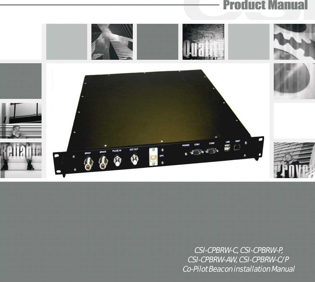
Westell CSI-CPBRW-CP THE CO-PILOT BEACON IS THE FIRST VIABLE LOCATION BASED SOLUTION FOR SIMULCAST CDMA DISTRIBUTED ANTENNA SYSTEMS (DASS). IT IS DESIGNED TO IMPROVE LOCATION ACCURACY OF CELL PHONES AND WIRELESS DEVICES OUTDOORS AND WITHIN BUILDINGS User Manual D960 1046 001 rB draft MANUAL ICEbreaker pmd
Westell, Inc. THE CO-PILOT BEACON IS THE FIRST VIABLE LOCATION BASED SOLUTION FOR SIMULCAST CDMA DISTRIBUTED ANTENNA SYSTEMS (DASS). IT IS DESIGNED TO IMPROVE LOCATION ACCURACY OF CELL PHONES AND WIRELESS DEVICES OUTDOORS AND WITHIN BUILDINGS D960 1046 001 rB draft MANUAL ICEbreaker pmd
Westell >
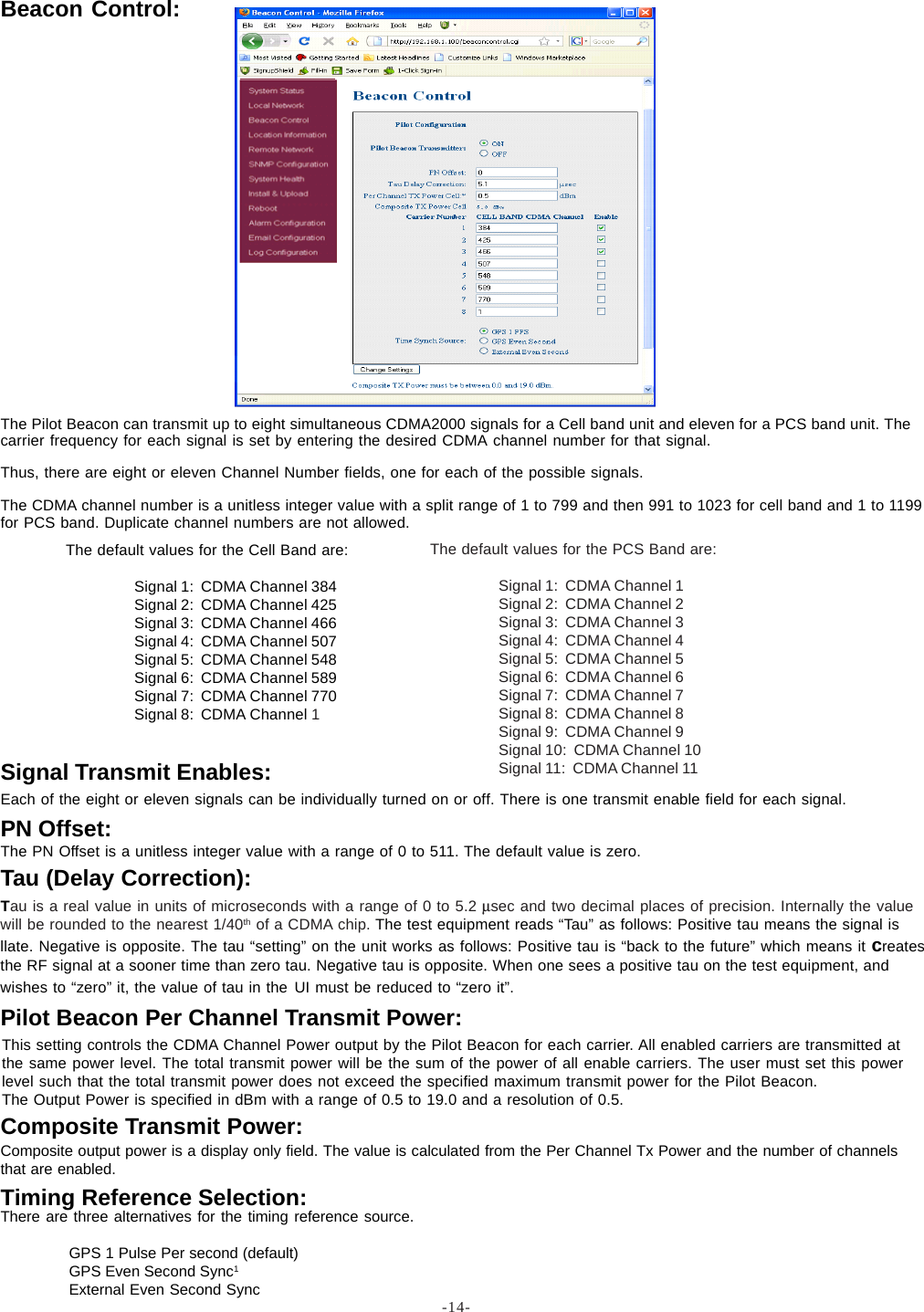
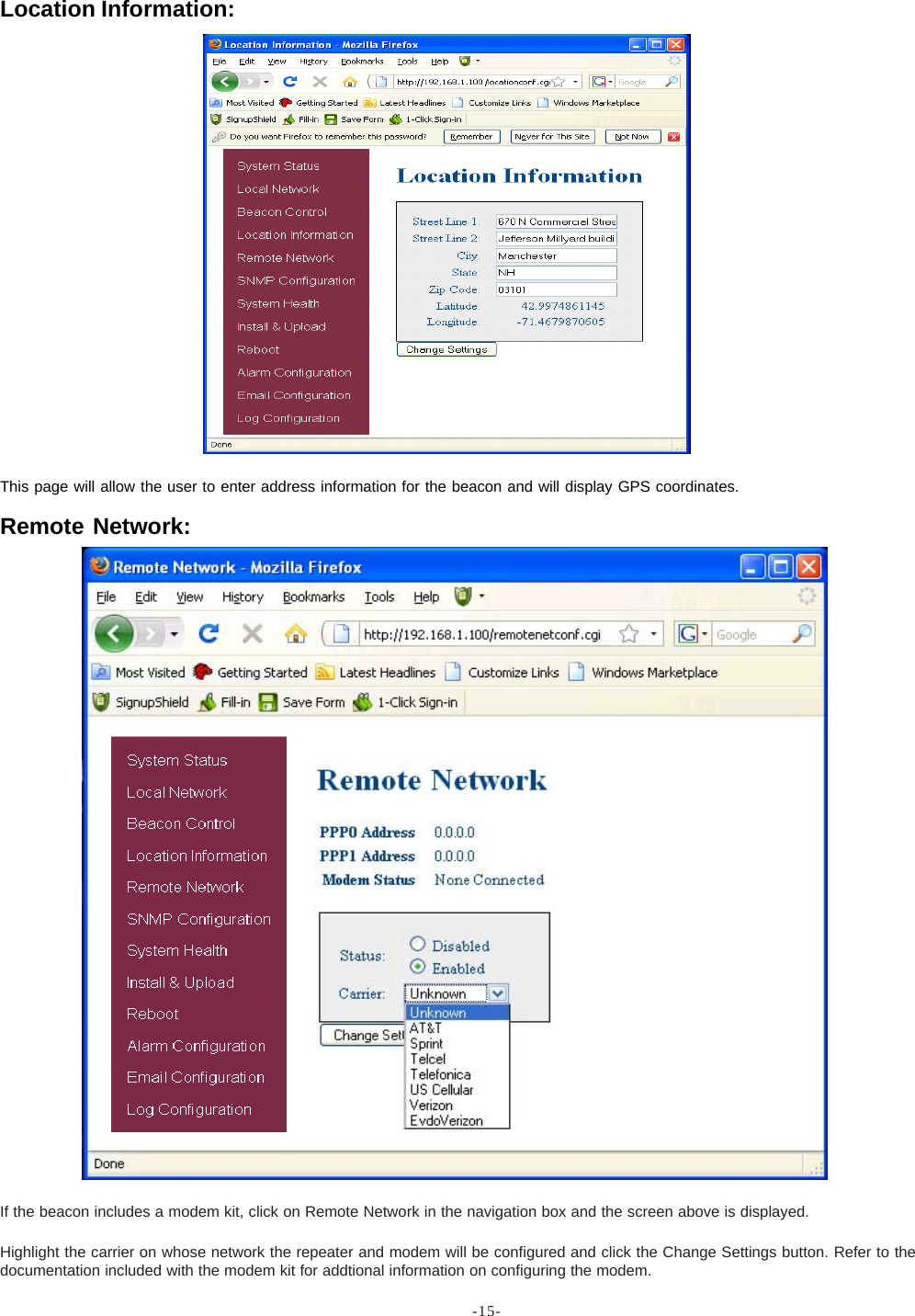
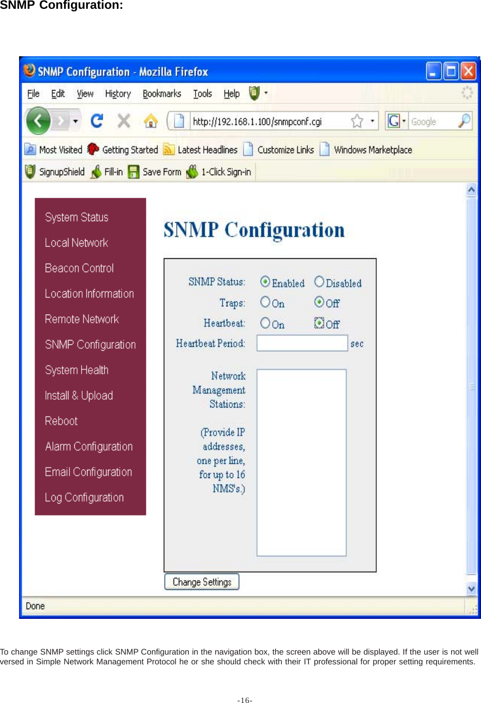
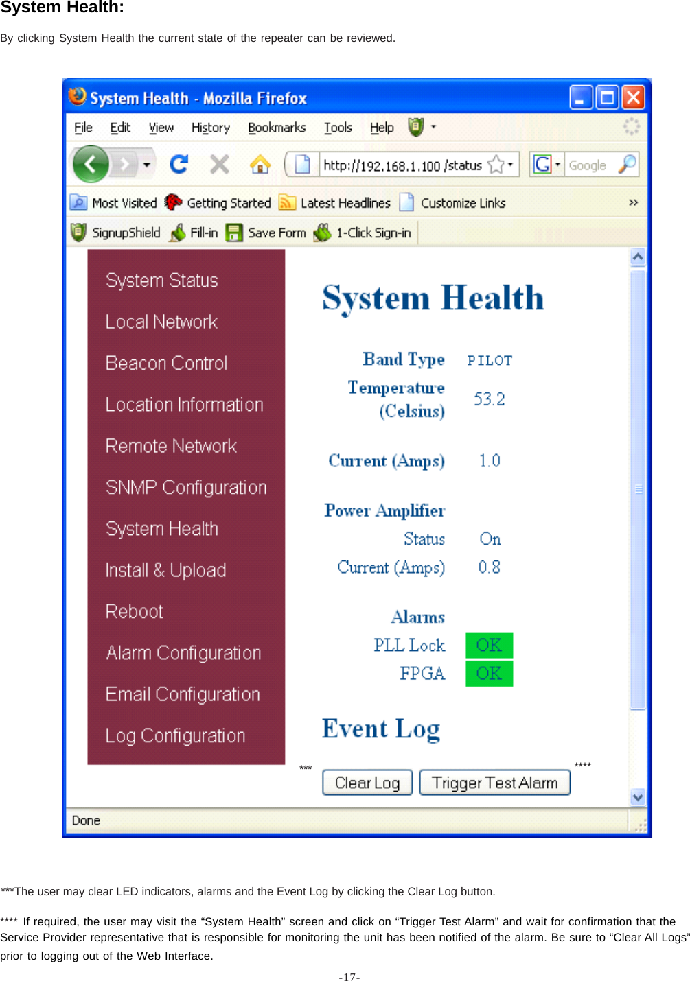
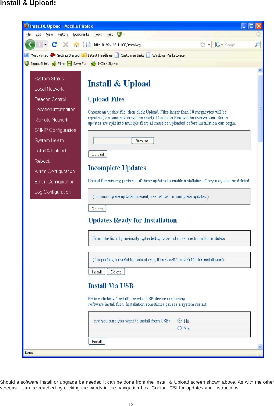
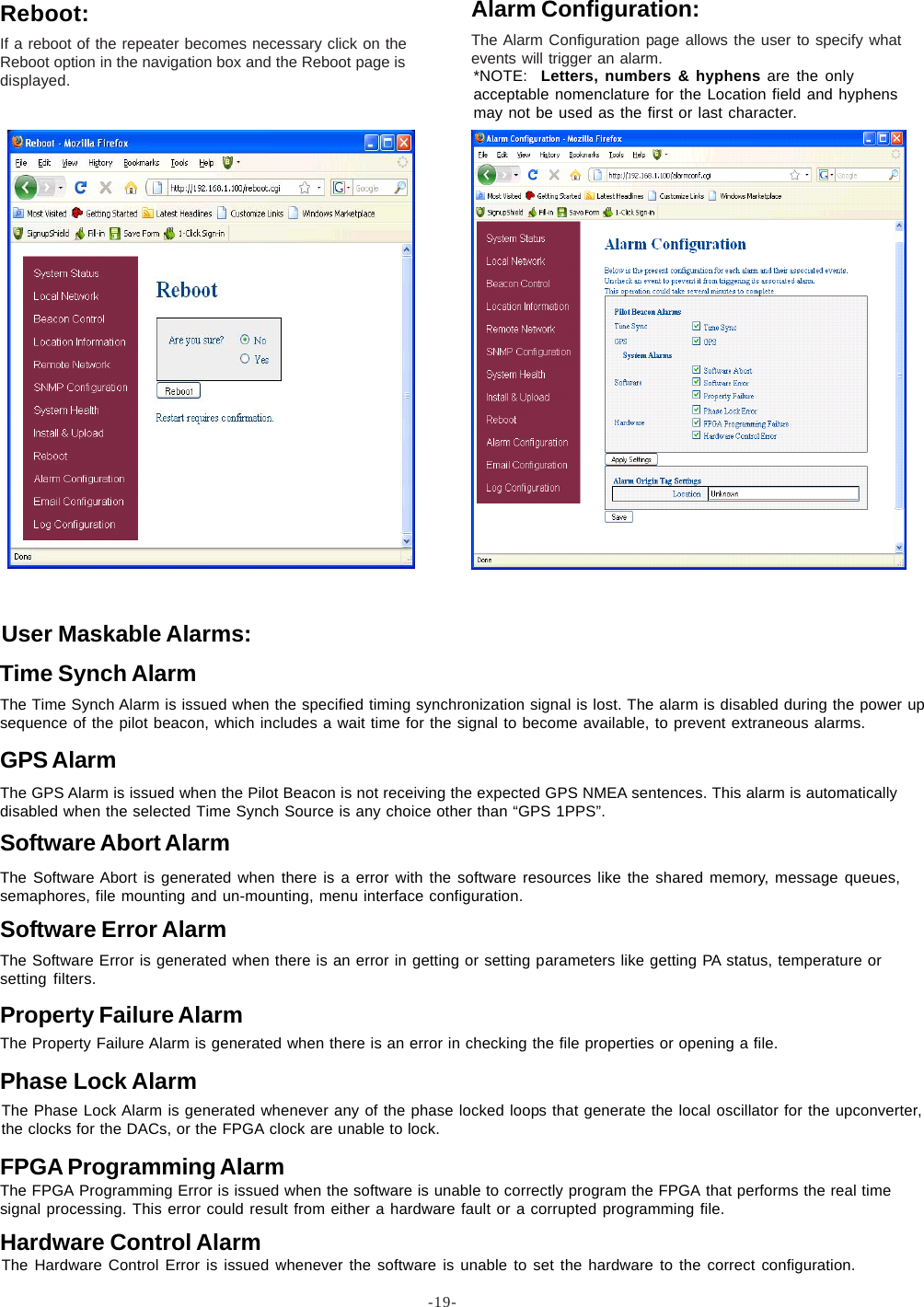
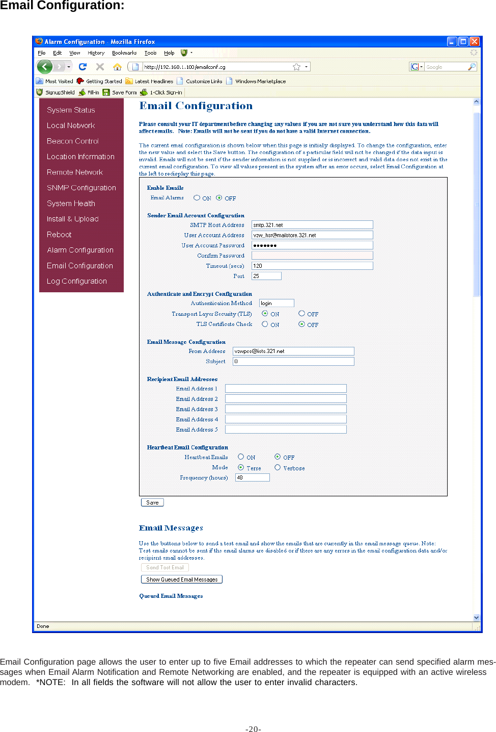
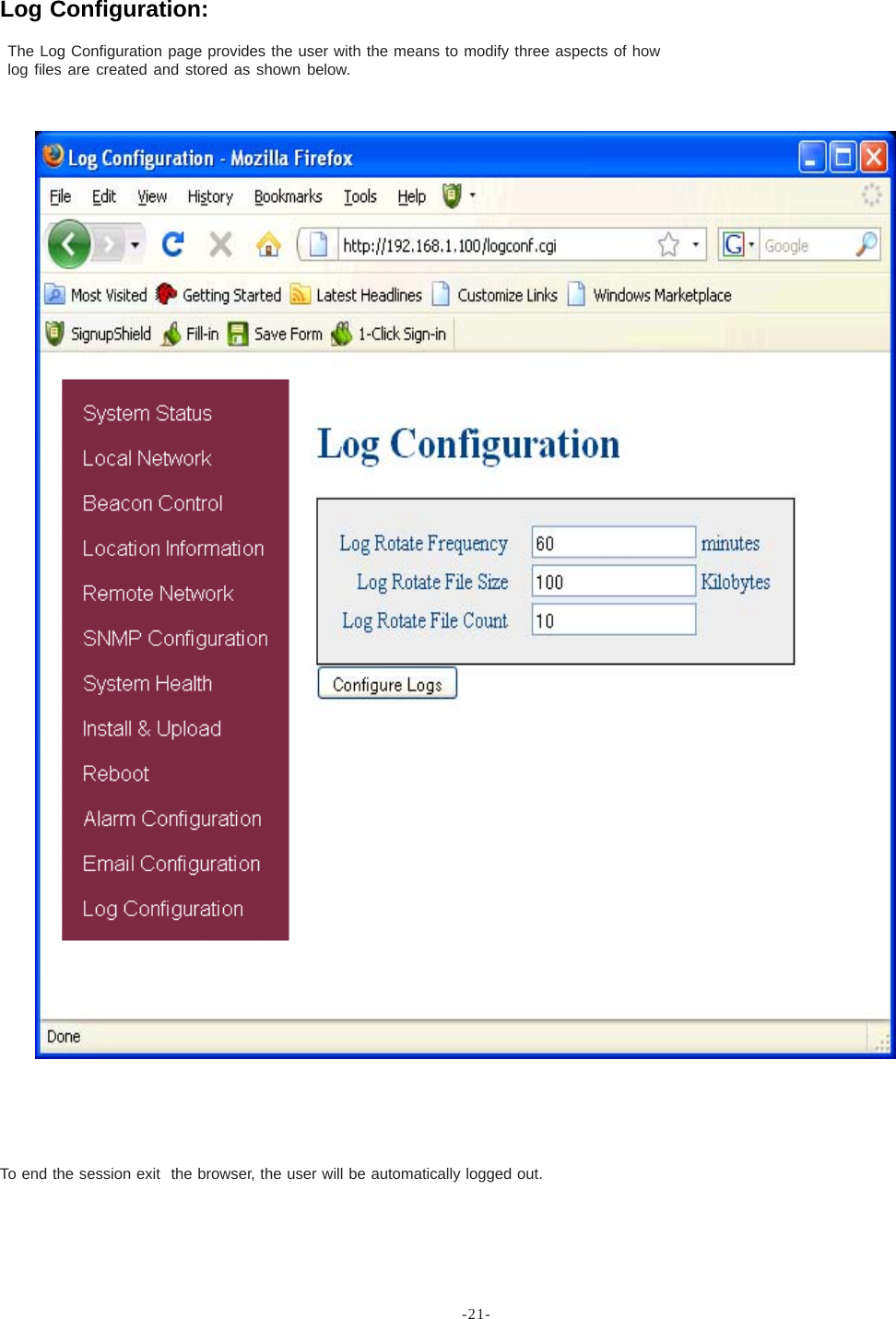
Users Manual