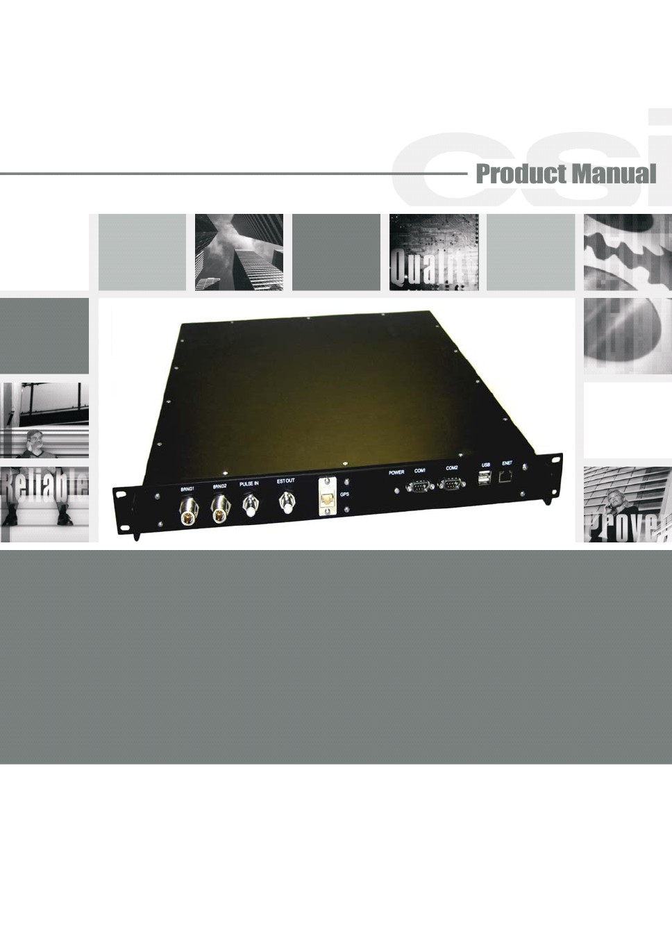
Westell CSI-CPBRW-CP THE CO-PILOT BEACON IS THE FIRST VIABLE LOCATION BASED SOLUTION FOR SIMULCAST CDMA DISTRIBUTED ANTENNA SYSTEMS (DASS). IT IS DESIGNED TO IMPROVE LOCATION ACCURACY OF CELL PHONES AND WIRELESS DEVICES OUTDOORS AND WITHIN BUILDINGS User Manual D960 1046 001 rB draft MANUAL ICEbreaker pmd
Westell, Inc. THE CO-PILOT BEACON IS THE FIRST VIABLE LOCATION BASED SOLUTION FOR SIMULCAST CDMA DISTRIBUTED ANTENNA SYSTEMS (DASS). IT IS DESIGNED TO IMPROVE LOCATION ACCURACY OF CELL PHONES AND WIRELESS DEVICES OUTDOORS AND WITHIN BUILDINGS D960 1046 001 rB draft MANUAL ICEbreaker pmd
Westell >
Users Manual
CSI-CPBRW-C, CSI-CPBRW-P,
CSI-CPBRW-AW, CSI-CPBRW-C/P
Co-Pilot Beacon installation Manual

Table of Contents
Product Registration Information:....................................................................................4
Document Purpose / Intended Users:.............................................................................4
Important Safety Information:............................................................................................4
Safety Guidelines:...............................................................................................................4
Application:...........................................................................................................................4
Acronyms and Definitions:.................................................................................................5
Product Introduction:...........................................................................................................5
Powering Up the Unit:........................................................................................................6
Local Communication Interface Ports:...........................................................................6
Functional Overview:..........................................................................................................6
EIA232 Pin Specifications:................................................................................................7
USB Interface:......................................................................................................................7
Ethernet:...............................................................................................................................7
Monitoring & Alarms:..........................................................................................................7
System Set-Up Considerations:.....................................................................................8
Wall Mounting the Pilot Beacon:.....................................................................................8
Important Installation Notes:...........................................................................................9
Optional Accessories:.......................................................................................................9
Environmental Requirements:......................................................................................10
Mechanical Specifications:.............................................................................................10
AC Power Specifications:................................................................................................10
Mechanical Drawing: ......................................................................................................11
Web based GUI Session:.................................................................................................12
System Status:....................................................................................................................12
Local Network:..................................................................................................................13
Beacon Control:.................................................................................................................14
Location Information:.......................................................................................................15
Remote Network:..............................................................................................................15
SNMP Configuration:........................................................................................................16
System Health:..................................................................................................................17
Install & Upload:...............................................................................................................18
Reboot:...............................................................................................................................19
User Maskable Alarms:...................................................................................................19
Alarm Configuration:.......................................................................................................19
Email Configuration:.......................................................................................................20
Log Configuration:...........................................................................................................21
Text Menu Interface (Local Access):..............................................................................22
Main Menu:.........................................................................................................................25
User Interface:...................................................................................................................25
Login:.................................................................................................................................25
Set Parameters Menu:...................................................................................................25
Pilot Beacon Configuration Menu:...............................................................................26
Networking Configuration Menu:..................................................................................27
Telnet Session (Remote Access):...............................................................................28
Additional Tips:................................................................................................................29
Industry Certifications/Registration Numbers:..........................................................31
One Year Limited Warranty:...........................................................................................31
Index:..................................................................................................................................32

-4-
This guide should be applied whenever a need exists to add pilot beacon capability to an existing system or
when this capability is being included with a new installation.
The general safety information in this guideline applies to both operating and service personnel. Specific
warnings and cautions will be found in other parts of this manual where they apply, but may not appear in this
summary. Failure to comply with these precautions or specific warnings elsewhere in the manual violates
safety standards of design, manufacture, and intended use of equipment. Cellular Specialties, Inc. assumes no
liability for the customer’s failure to comply with these requirements:
Grounding
This pilot beacon system is designed to operate from 100-240 VAC and should always
be operated with the ground wire properly connected. Do not remove or otherwise alter the
grounding lug on the power cord.
Explosive Atmospheres
To avoid explosion or fire, do not operate this product in the presence of flammable
gases or fumes.
Lightning Danger
Do not install or make adjustments to this unit during an electrical storm. Use of a suitable lightning
arrester, such as CSI’s model number CSI-CAP, is very strongly recommended.
No User Serviceable Parts Inside
HAZARDOUS VOLTAGES ARE PRESENT WHEN THE COVER IS REMOVED. Opening the chassis will void
your warranty. If you suspect a malfunction with this product, call your dealer or the Cellular Specialties
Support Line at: (603) 626-6677, Toll Free (USA) 1-877-844-4274.
The purpose of this document is to provide a step-by-step procedure to help the experienced technician/
engineer install and commission an in-building wireless enhancement pilot beacon system. Following the
procedures outlined will minimize risks associated with modifying a live system and prevent service interrup-
tions. This document assumes the technician/engineer understands the basic principles and functionality
involved with the system. It is geared to the practical concerns of the installer.
Antennas used for the purpose of radiating signals indoors are limited to a maximum gain of 3 dBi. Each antenna must be
positioned to observe minimum separation requirements from all users and bystanders. The following guidelines should be
used when considering separation distances.
INDOOR antennas must be placed such that, under normal conditions, personnel cannot come within 20 cm (~8.0 in.) from
any inside antenna. Adhering to this minimum separation will ensure that the employee or bystander cannot exceed RF
exposures beyond the maximum permissible limit as defined by section 1.1310 i.e. limits for General Population/Uncontrolled
Exposure.
Document Purpose / Intended Users:
Application:
Safety Guidelines:
Important Safety Information:
Product Registration Information:
DISCLAIMER: All information and statements contained herein are accurate to the best of the knowledge of Cellular Specialties, Inc.
(CSI), but Cellular Specialties makes no warranty with respect thereto, including without limitation any results that may be obtained from
the products described herein or the infringement by such products of any proprietary rights of any persons. Use or application of such
information or statements is at the users sole risk, without any liability on the part of Cellular Specialties, Inc. Nothing herein shall be
construed as licence or recommendation for use, which infringes upon any proprietary rights of any person. Product material and
specifications are subject to change without notice. Cellular Specialties’ standard terms of sale and the specific terms of any particular
sale apply.
The serial number may be found on the label on the bottom panel near the power
connectors. Note this number below. Retain this manual, along with proof of
purchase, to serve as a permanent record of your purchase.
MODEL NUMBER SERIAL NUMBER DATE OF PURCHASE
POINT OF SALE COMPANY
NOTE: This equipment has been tested and found to comply with the limits for a Class A digital device,
pursuant to Part 15 of the FCC rules. These limits are designed to provide reasonable protection against
harmful interference when the equipment is operated in a commercial environment. This equipment generates,
uses and can radiate radio frequency energy and, if not installed and used in accordance with the instruction
manual, may cause harmful interference to radio communications. Operation of this equipment in a residential
area is likely to cause harmful interference in which case the user will be required to correct the interference
at his own expense.
Radio and Television Interference
- 5 -
The pilot beacon generator facilitates E911 and other location based services (LBS) for in building and/or DAS based installations of
CDMA2000/1xEV-DO cellular networks. In these situations the normal methods based for location determination, direct reception of GPS
by the mobile station or triangulation using the signals from multiple base stations, do not work. Signals from the GPS system are
sufficiently weak that even if the mobile station’s GPS receiver might ultimately be able to lock on to the satellites, the acquisition time will be
too long. And since indoor service is typically provided either by a single strong local cell or by using a repeater, there aren’t multiple
signals on which to triangulate while DAS based deployments result in too many signals with indeterminate timing. By placing a pilot signal
at a known PN offset the LBS algorithm can quickly and reliably be made aware that it is within a specific building or other location where
normal location determining solutions are ineffective. This information can be used to aid the GPS receiver in acquiring signals if they are
present or be used as a position report directly until more accurate information becomes available.
3GPP2 The standards body comprised of representatives of interested companies that is responsible for the
development and maintenance of the operational standards for the CDMA2000 system. Http://
www.3gpp2.org
AGC Automatic Gain Control
CDMA Code Division (or, Domain) Multiple Access: The general term for the technology used in the CDMA2000
system as well as others. Also a shorthand reference to the CDMA2000 system and its derivatives
such as 1xEV-DO
Chip A single element, a ‘1’ or a ‘0’, of the PN Sequence in a CDMA system. The chip rate for the CDMA2000
system is 1.2288 Mchips/second.
CSI Cellular Specialties Incorporated
DAS Distributed Antenna System
ERP Effective Radiated Power
EST Even Second Tick: In the CDMA2000 cellular system all time values are referenced to the start of the
even seconds of time as indicated by GPS.
FCC Federal Communications Commission
FPGA Field Programmable Gate Array
GPS Global Positioning System
IF Intermediate Frequency
LED Light Emitting Diode
NEMA National Electrical Manufacturers Association
PA Power Amplifier
PN Pseudo random Number: A number chosen by some algorithm that approximates a random process.
Can be short for “PN Sequence”, “PN Number”, or “PN Offset” when discussing the CDMA2000
system.
PN Number In the CDMA2000 system only a subset of the possible PN Offsets are used for base station
identification. Each of these allowed offsets is given a unique number from 0 to 511.
PN Offset In the CDMA2000 System each base station is identified by the offset in time from the EST at which the
start of the Pilot PN Sequence occurs. The offset is specified in terms of number of chips.
PN Sequence A sequence of pseudo random numbers. In the CDMA2000 system several such sequences are used.
The one relevant to ICEBreaker is the Pilot, or Short, sequence which is a 215 element long sequence of
ones and zeros.
PPS Pulse per Second: Refers the pulse repetition rate of the timing signal used as a time reference.
RF Radio Frequency
SBC Single Board Computer
Tau Timing Offset or Delay Adjustment: In the CDMA2000 system the timing of the downlink signal is
required to be aligned with the EST as it is transmitted from the antenna. Tau allows the timing of the
internal PN Sequence to be adjusted to compensate for the delays of the base station hardware such
that the timing will be correct at the antenna
USB Universal Serial Bus
Acronyms and Definitions:
Product Introduction:
- 6-
During Power up, the pilot beacon will require approximately three minutes for the internal computer to boot up.
During this time the LEDs on the front panel may light and go out several times. When boot is complete and no alarm
conditions exist, none of the LED indicators will be illuminated. The CSI logo is illuminated when ever the pilot is powered.
Do not unplug the unit while it is in the boot up process!
Powering Up the Unit:
To allow monitoring and control, the pilot beacon is equipped with four ports that provide external communication
access (1 Ethernet CAT-5, 2 DB-9 serial, and 1 USB). The Ethernet, CAT-5 port is provided as a primary communica-
tions port to the PC. One serial interface, COM 1, provides communications to local PC. The USB interface provides a
means to download files from a memory device. The DB-9 pin assignments of COM 1 conform to the standard
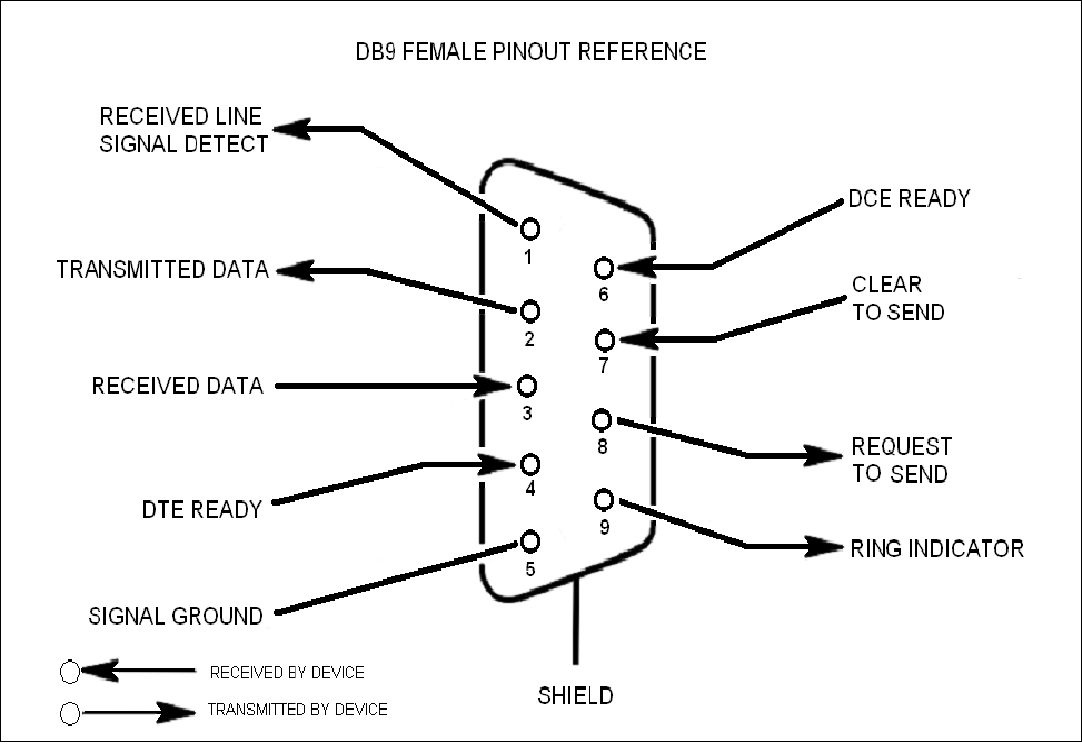
Electronic Industries Association (EIA232) specification. A diagram of the pin descriptions is provided on this page for
reference.
Connecting a null modem cable to the COM 1 port and using a terminal emulation program with a PC will allow
communication to the control processor’s Text Menu Interface (TMI). See command line interface section for further
detail.
The proprietary external GPS receiver connection is made at the port labeled “GPS Receiver”. Do not connect other
devices or non-straight-through serial extension cables to this port. Place the GPS receiver in a location with
the best view of the unobstructed sky that is possible, although a 100% open view of the sky is not necessary to
achieve a stable time lock.
Functional Overview:
Local Communication Interface Ports:
- 7 -
EIA232 Pin Specifications:
The diagram above is for reference only, it’s intended to provide a quick source for pinout information in the event it should
be necessary to adapt your serial cable because of an unusual connector configuration. In the vast majority of cases this
information will not be needed.
There are no physical connections provided to specifically communicate system or alarm status. This informa-
tion is embedded in the information accessible via the communication ports described earlier.
The Universal Serial Bus (USB) interface conforms to Intel’s Universal Host Controller Interface (UHCI) version
1.1 dated March 21, 1996. This interface will support data transfer rates up to 12 Mbps and can be used for
software updates.
The Ethernet AUI conforms to IEEE 802.3 and is capable of supporting 10/100 Mbps communications speeds.
This port is used to provide access to the UI.
USB Interface:
Ethernet:
Monitoring & Alarms:
-8-
All cables should be checked for shorts and opens. Also verify that there are no cables with loose or poor
connections. It is critical that the installer contact the service provider before the system is turned on.
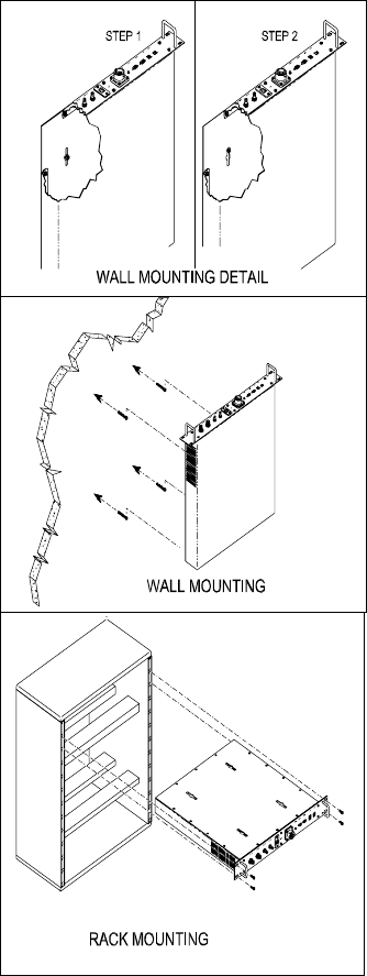
The following diagram illustrates the best method for mounting the pilot beacon to a wall in an typical
installation.
System Set-Up Considerations:
Wall Mounting the Pilot Beacon:
- 9 -
•The installer should refer to the Safety Guidelines section and the Important Safety Information section for proper
antenna selection and installation. To avoid serious injury or death and damage to the pilot beacon, do not install server
antennas near overhead power lines or high power components. Allow enough distance so that if antennas should
fall they will not come in contact with those components.
••
••
•Close proximity to the server antennas with the pilot beacon in operation may expose the user or installer to RF
fields that exceed FCC limits for human exposure.
WARNING! AMPLIFIER OR HANDSET DAMAGE MAY OCCUR IF A HANDSET IS CONNECTED DIRECTLY TO THE PILOT
BEACON OR THE COAX THAT LEADS TO THE PILOT BEACON.
A complete line of accessories is available from Cellular Specialties, Inc. Check with your CSI distributor for any additional items
needed. Below are just a few examples suitable for most in-building needs.
•Directional Couplers
6dB - model number: CSI-DC6/700-2K/N
10dB - model number: CSI-DC10/700-2K/N
15dB - model number: CSI-DC15/700-2K/N
20dB - model number: CSI-DC20/700-2K/N
30dB - model number: CSI-DC30/700-2K/N
Battery backup, 4 hr Single band
2 hour dual band - model number: CS48-985-601
•Power Dividers
2:1 - model number: CSI-SPD2/700-2.5K/N
3:1 - model number: CSI-SPD3/700-2.5K/N
4:1 - model number: CSI-SPD4/700-2.5K/N
•Grounding Kit - model number: CSI-GKIT
•Lightning Arrestor - model number: CSI-CAP
•Inside Omnidirectional Antenna
Quad-band - model number: CSI-AO/700/2.5K/3
Optional Accessories:
Important Installation Notes:
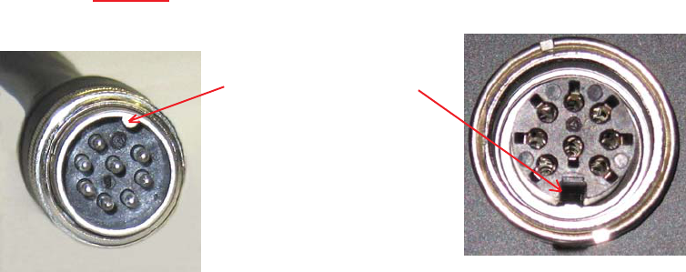
Warning: Power supply cable connector is keyed for proper orientation
and is designed to lock into place.
Keyed for proper
alignment, do not
force connector
into place.

- 10 -
Color Satin Black
AC Voltage 100 - 240 VAC External Power Supply
AC Power Frequency 47 - 63 Hz
Box Weight 10.1 / 4.6 lbs/kg
Box Thermal Management Fan Cooled
Surface Coating Powder Coat
AC Current 1.7 Amps @ 120 VAC
0.9 Amps @ 230 VAC
Parameter Specification Notes
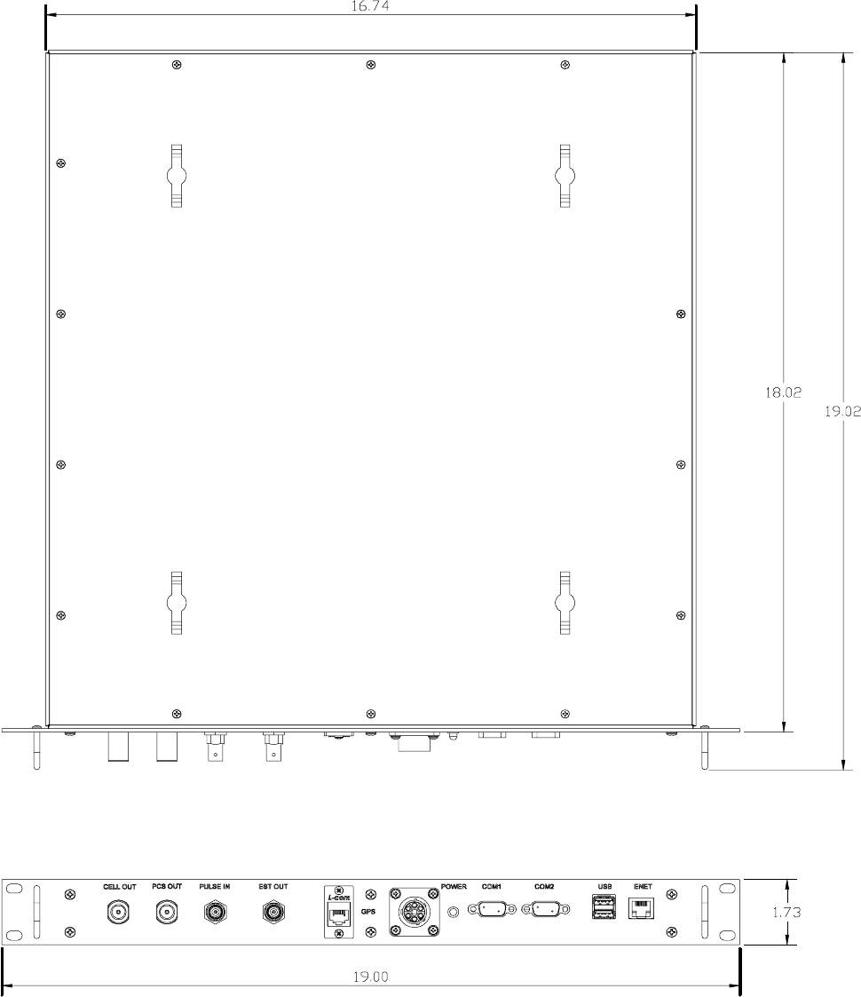
Pilot Beacon Size
Height 1.73 in.
Width 19.00 in.
Depth
Heat Output 500 BTU/Hr
Relative Humidity 5% to 95% Non-condensing
Industrial Dust <15mg/m3 Telcordia GR-63-CORE
Temperature Range -30 to +48 C
(-22 to +118 F)
00
00
Mechanical Specifications:
AC Power Specifications:
Parameter Specification Notes
Environmental Requirements:
Parameter Specification Notes
- 11 -
Mechanical Drawing:
-12-
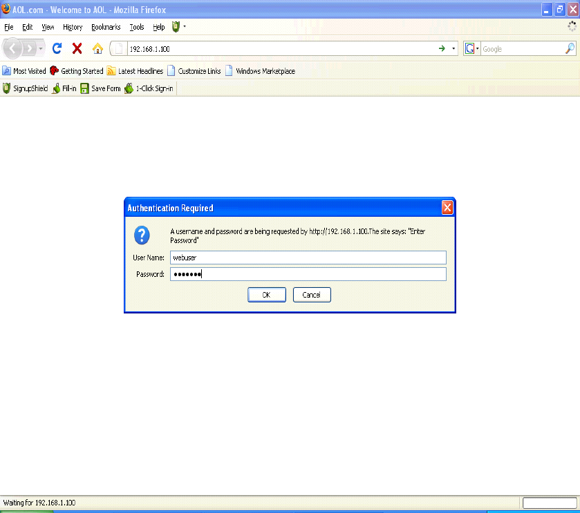
Primary access to the unit is gained using a LAN connection and a web browser program such as Firefox by Mozilla, or Internet
Explorer from Microsoft. The beacon ships with the default IP address of 192.168.1.100, but it can be changed later if required.
If connecting directly to the unit from a laptop or PC with a crossover CAT-5E cable or over a LAN the user types the IP
address of the unit into the browser address line to connect. (Note: Most users will need to update the TCP/IP settings on their
computer to enable connection to a host that has a static IP. Select “Use the following IP Address” and enter the IP Address as
follows: 192.168.1.x, where “x” = any number from 2 to 254 inclusive other than 100. The subnet mask is 255.255.255.0.
Questions pertaining to these settings should be referred to the user’s IT department or you may refer to the Additional Tips
section at the end of this manual.) When connection is made the user will be prompted for a user name and password. For the
purpose of the GUI session, the default user name is webuser and the password is csi1234. This can also be changed as
required. Internet access is not required to use the GUI. (Note: If you are connecting using a laptop, verify that your Ethernet port
is powered. Some laptops will not allow Ethernet connection when on battery power. If this is the case with the laptop you are
using you will need to plug it in or update the power settings.)
Web based GUI Session:
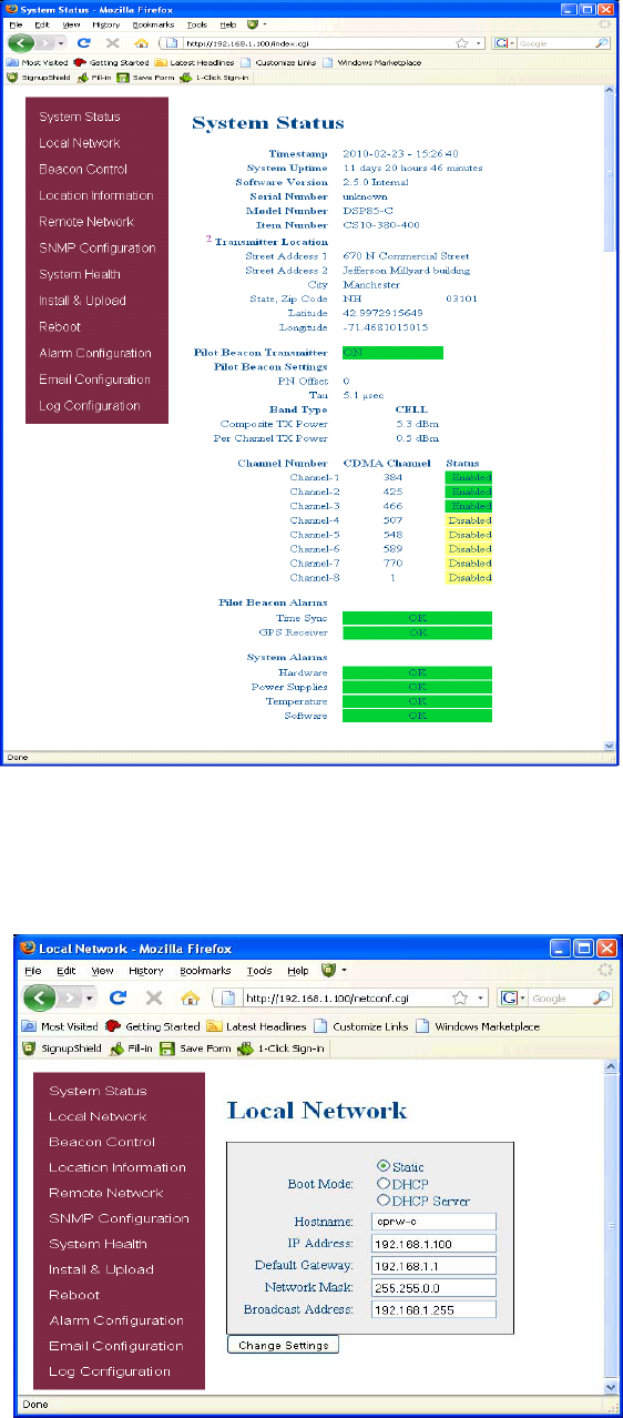
When login is complete the user is brought to the system status page. The links shown in the
navagation box on the left are activated by clicking on them.
System Status:
-13-
If the user selects Local Network from the System Status page, the following screen is displayed
and from here network configuration can be modified as required. The default is set to Static. Check
with your IT department for explanation and approval of the DHCP and DHCP Server options you
plan to use before you select them.
Local Network:
-14-
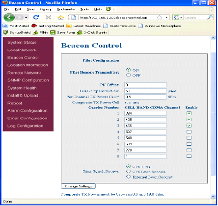
The Pilot Beacon can transmit up to eight simultaneous CDMA2000 signals for a Cell band unit and eleven for a PCS band unit. The
carrier frequency for each signal is set by entering the desired CDMA channel number for that signal.
Thus, there are eight or eleven Channel Number fields, one for each of the possible signals.
The CDMA channel number is a unitless integer value with a split range of 1 to 799 and then 991 to 1023 for cell band and 1 to 1199
for PCS band. Duplicate channel numbers are not allowed.
Beacon Control:
The default values for the Cell Band are:
Signal 1: CDMA Channel 384
Signal 2: CDMA Channel 425
Signal 3: CDMA Channel 466
Signal 4: CDMA Channel 507
Signal 5: CDMA Channel 548
Signal 6: CDMA Channel 589
Signal 7: CDMA Channel 770
Signal 8: CDMA Channel 1
The default values for the PCS Band are:
Signal 1: CDMA Channel 1
Signal 2: CDMA Channel 2
Signal 3: CDMA Channel 3
Signal 4: CDMA Channel 4
Signal 5: CDMA Channel 5
Signal 6: CDMA Channel 6
Signal 7: CDMA Channel 7
Signal 8: CDMA Channel 8
Signal 9: CDMA Channel 9
Signal 10: CDMA Channel 10
Signal 11: CDMA Channel 11
Each of the eight or eleven signals can be individually turned on or off. There is one transmit enable field for each signal.
Signal Transmit Enables:
PN Offset:
The PN Offset is a unitless integer value with a range of 0 to 511. The default value is zero.
Tau is a real value in units of microseconds with a range of 0 to 5.2 μsec and two decimal places of precision. Internally the value
will be rounded to the nearest 1/40th of a CDMA chip. The test equipment reads “Tau” as follows: Positive tau means the signal is
llate. Negative is opposite. The tau “setting” on the unit works as follows: Positive tau is “back to the future” which means it creates
the RF signal at a sooner time than zero tau. Negative tau is opposite. When one sees a positive tau on the test equipment, and
wishes to “zero” it, the value of tau in the UI must be reduced to “zero it”.
Pilot Beacon Per Channel Transmit Power:
This setting controls the CDMA Channel Power output by the Pilot Beacon for each carrier. All enabled carriers are transmitted at
the same power level. The total transmit power will be the sum of the power of all enable carriers. The user must set this power
level such that the total transmit power does not exceed the specified maximum transmit power for the Pilot Beacon.
The Output Power is specified in dBm with a range of 0.5 to 19.0 and a resolution of 0.5.
Composite Transmit Power:
Composite output power is a display only field. The value is calculated from the Per Channel Tx Power and the number of channels
that are enabled.
There are three alternatives for the timing reference source.
GPS 1 Pulse Per second (default)
GPS Even Second Sync1
External Even Second Sync
Tau (Delay Correction):
Timing Reference Selection:
-15-
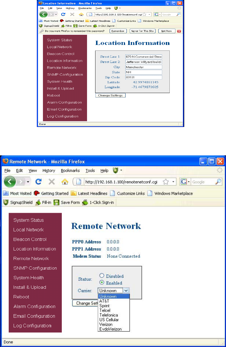
Location Information:
This page will allow the user to enter address information for the beacon and will display GPS coordinates.
If the beacon includes a modem kit, click on Remote Network in the navigation box and the screen above is displayed.
Highlight the carrier on whose network the repeater and modem will be configured and click the Change Settings button. Refer to the
documentation included with the modem kit for addtional information on configuring the modem.
Remote Network:
-16-
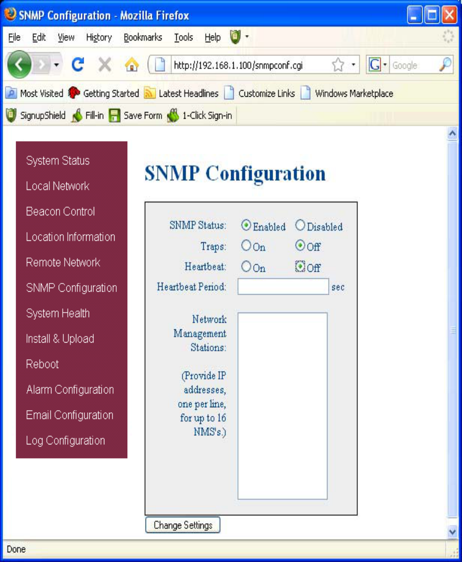
To change SNMP settings click SNMP Configuration in the navigation box, the screen above will be displayed. If the user is not well
versed in Simple Network Management Protocol he or she should check with their IT professional for proper setting requirements.
SNMP Configuration:
-17-
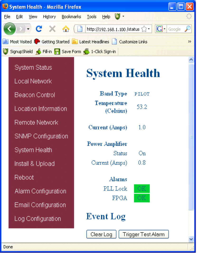
By clicking System Health the current state of the repeater can be reviewed.
System Health:
**** If required, the user may visit the “System Health” screen and click on “Trigger Test Alarm” and wait for confirmation that the
Service Provider representative that is responsible for monitoring the unit has been notified of the alarm. Be sure to “Clear All Logs”
prior to logging out of the Web Interface.
****
***The user may clear LED indicators, alarms and the Event Log by clicking the Clear Log button.
***
-18-
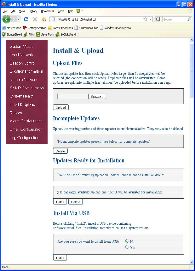
Should a software install or upgrade be needed it can be done from the Install & Upload screen shown above. As with the other
screens it can be reached by clicking the words in the navigation box. Contact CSI for updates and instructions.
Install & Upload:
-19-
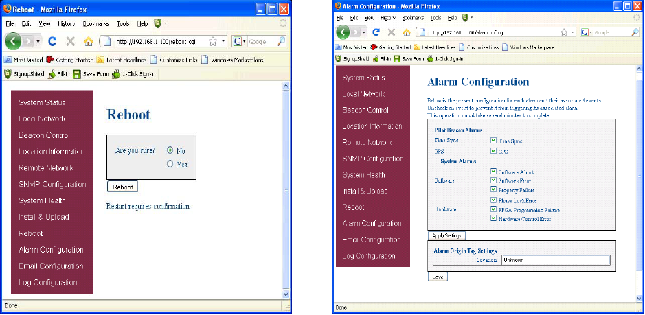
If a reboot of the repeater becomes necessary click on the
Reboot option in the navigation box and the Reboot page is
displayed.
Reboot: Alarm Configuration:
The Alarm Configuration page allows the user to specify what
events will trigger an alarm.
Software Error Alarm
The Software Error is generated when there is an error in getting or setting parameters like getting PA status, temperature or
setting filters.
Property Failure Alarm
The Property Failure Alarm is generated when there is an error in checking the file properties or opening a file.
The Phase Lock Alarm is generated whenever any of the phase locked loops that generate the local oscillator for the upconverter,
the clocks for the DACs, or the FPGA clock are unable to lock.
Phase Lock Alarm
The FPGA Programming Error is issued when the software is unable to correctly program the FPGA that performs the real time
signal processing. This error could result from either a hardware fault or a corrupted programming file.
FPGA Programming Alarm
The Hardware Control Error is issued whenever the software is unable to set the hardware to the correct configuration.
Hardware Control Alarm
User Maskable Alarms:
Time Synch Alarm
The Time Synch Alarm is issued when the specified timing synchronization signal is lost. The alarm is disabled during the power up
sequence of the pilot beacon, which includes a wait time for the signal to become available, to prevent extraneous alarms.
GPS Alarm
The GPS Alarm is issued when the Pilot Beacon is not receiving the expected GPS NMEA sentences. This alarm is automatically
disabled when the selected Time Synch Source is any choice other than “GPS 1PPS”.
Software Abort Alarm
The Software Abort is generated when there is a error with the software resources like the shared memory, message queues,
semaphores, file mounting and un-mounting, menu interface configuration.
*NOTE: Letters, numbers & hyphens are the only
acceptable nomenclature for the Location field and hyphens
may not be used as the first or last character.
-20-
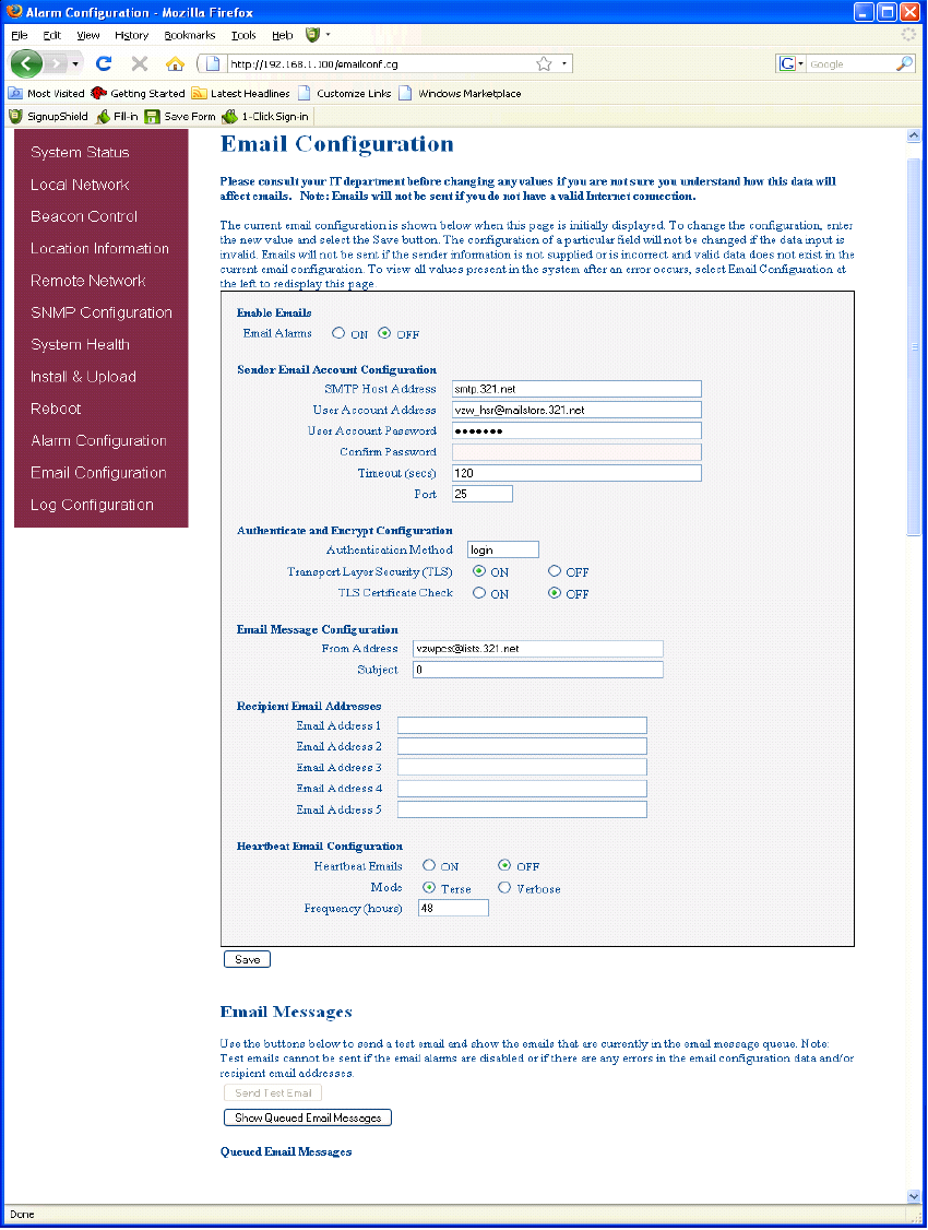
Email Configuration page allows the user to enter up to five Email addresses to which the repeater can send specified alarm mes-
sages when Email Alarm Notification and Remote Networking are enabled, and the repeater is equipped with an active wireless
modem. *NOTE: In all fields the software will not allow the user to enter invalid characters.
Email Configuration:
-21-
To end the session exit the browser, the user will be automatically logged out.
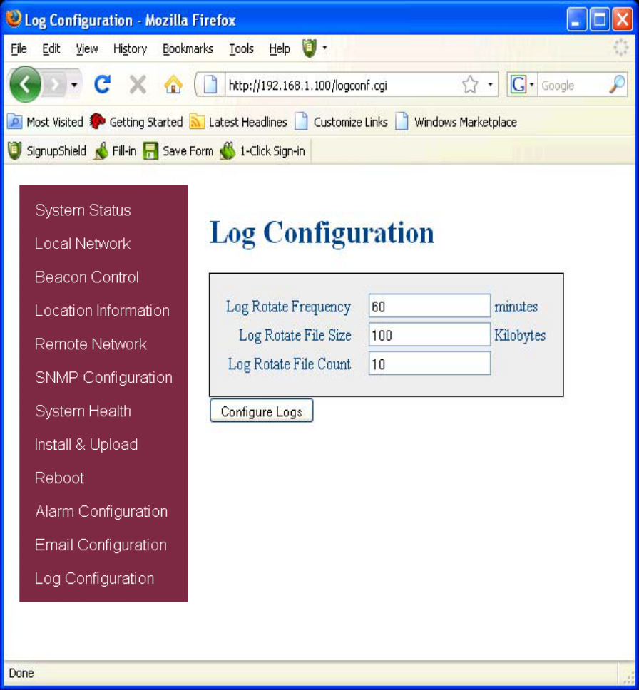
The Log Configuration page provides the user with the means to modify three aspects of how
log files are created and stored as shown below.
Log Configuration:
-22-
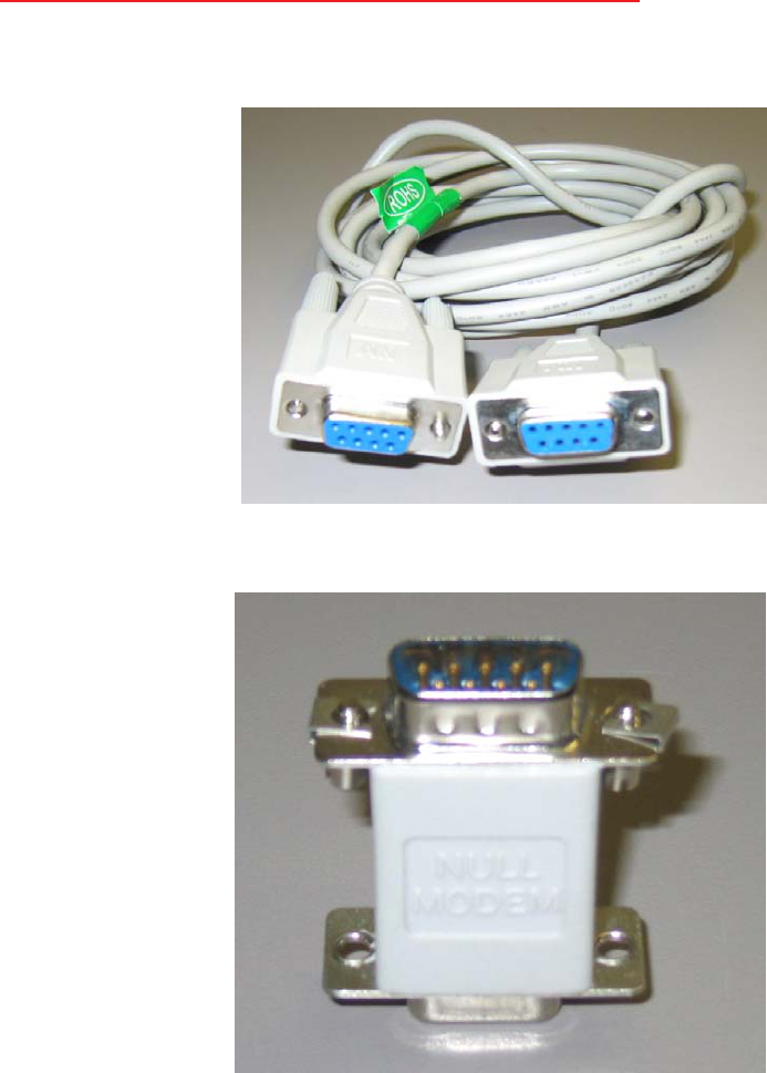
Figure 1
Figure 2
Local access to the pilot beacon TMI, also known as the console interface, is made by connecting a serial cable (optional), as shown in
figure 1, from the serial connector of the laptop the serial port on the bottom end panel of the pilot beacon. This connector is labeled COM
1. Warning: do not attach the serial cable to the port labeled GPS RECEIVER. In some cases, if the gender of the connector is not
the same as shown in figure 1, a null modem adapter (optional) as shown in figure 2 may also be required.
Text Menu Interface (Local Access):
Many terminal emulation programs will work if properly configured. In the following description, “TeraTerm” is used to establish the TMI
session. This program is readily available via the Internet and is free from Ayera Technologies at:
http://www.ayera.com/teraterm/
TeraTerm Pro Web works on Windows 95/98, 2000, XP. Here is the latest TeraTerm Pro Web release:
Version 3.1.3, October 8, 2002. ttpro313.zip
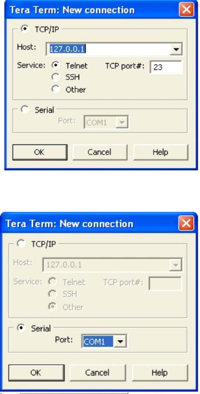
When the program is started, the following screen is displayed.
Select the Serial radio button and press OK as shown below.
Note: It may be necessary, in the System Properties section of the control panel; using Device
Manager to determine what COM port your computer uses for the communications port. In this case it is COM 1. This is not to be
confused with the serial port on the bottom panel of the repeater labeled COM 1.
-23-
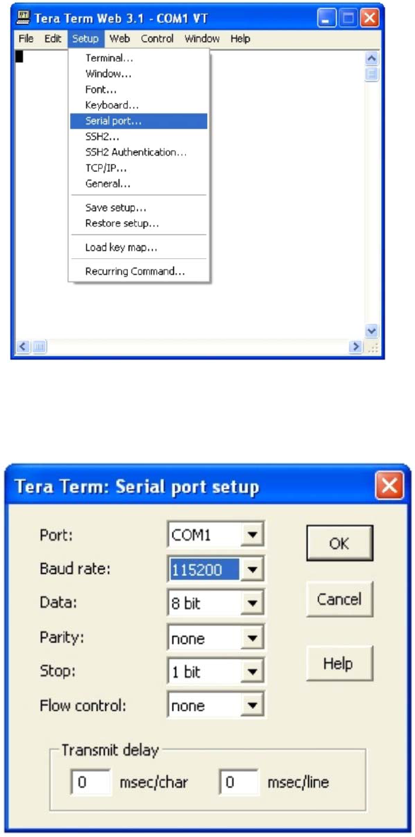
Pressing “OK” will open up a blank dialog screen. Go to the setup dropdown menu and select Serial port to make changes to the
serial port setup.
Configure the terminal program for the correct COM port, in this case COM 1 and 115200 baud rate as shown below.
-24-
-25-
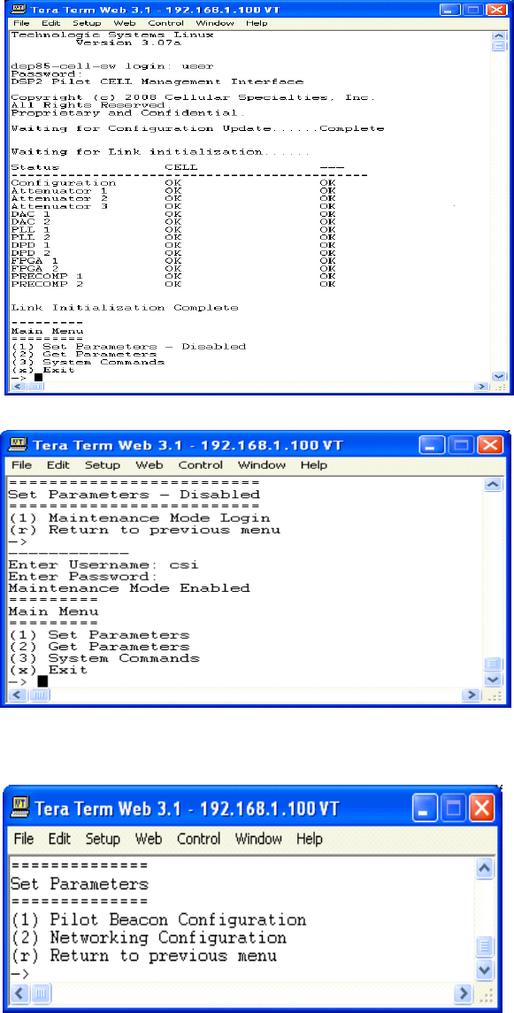
Set Parameters Menu:
Once the maintenance mode login is performed successfully the main menu will be displayed again but without the “(Disabled)”
qualifier on the “Set Parameters” choice.
When “Set Parameters” is first selected the unit will ask for the maintenance mode login.
Upon successful login the unit displays the main menu.
Main Menu:
Once the unit has completed its boot up and link initialization phases it will display the login prompt. The username is “user” and
the password is “csi1234”.
Login:
User Interface:
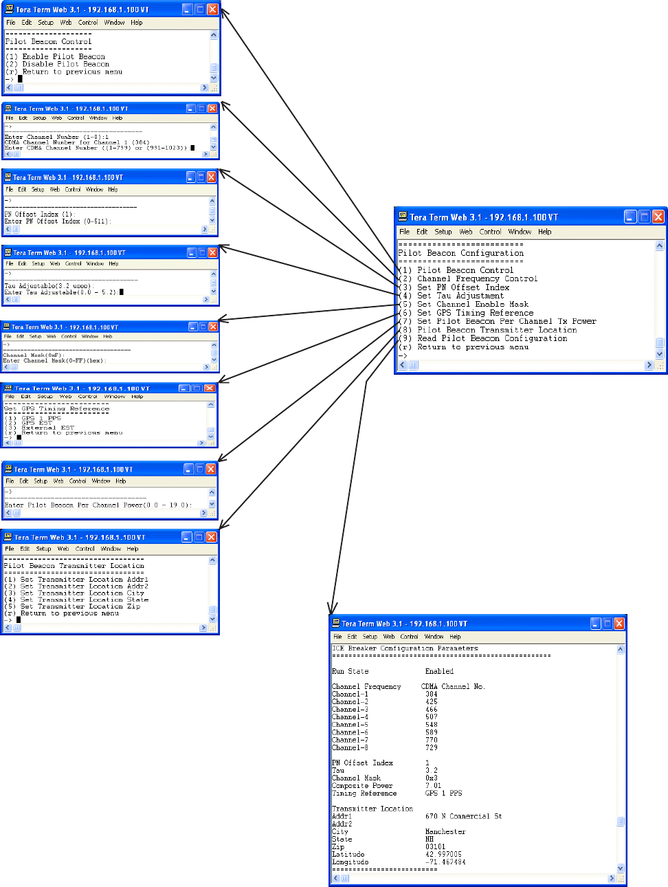
Pilot Beacon Configuration is entered by
pressing the number 1 from the Set Parameters
menu and the above screen is displayed. The
same level of control is available as with that
described for the GUI. Examples of each
selection screen is shown to the left.
Pilot Beacon Configuration Menu:
-26-
-27-
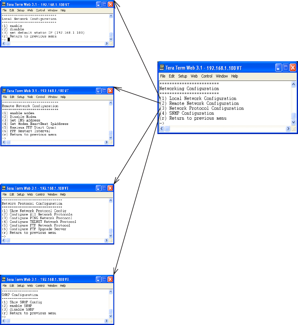
Networking Configuration Menu:
The Networking configuration menu is entered
by pressing the number 2 from the Set
Parameters menu and the above screen is
displayed. The same level of control is available
as with that described for the GUI. Examples
of each selection screen is shown to the left.
Remote access to the pilot beacon may be gained through a LAN connection and a terminal emulation program for TCP/IP. As with the
serial connection, many terminal emulation programs will work, if properly configured. In the following description, “TeraTerm” is used
to establish the Telnet session. Also, it will be required that the network configuration of the computer and the pilot beacon being
controlled be set up with the same Sub Net and Sub Net Mask in order to establish a link. In other words, the IP addresses of both the
computer used and the pilot beacon must use the same group of IP address number sets. For example, the pilot beacon ships with the
default IP address of 192.168.1.100 and a Sub Net Mask of 255.255.255.0. In order to connect, the computer to be used for the link
would normally need an IP address of something like 192.168.1.12 with a Sub Net Mask of 255.255.255.0, the same Sub Net Mask as
the pilot beacon. In this example note: the last digit of the IP address may be any number except 1,100 and 255. Configuring your PC is
normally fairly straight forward but it does vary somewhat with the operating system involved. If you require assistance, contact your
IT department and they will be able to set up your PC for you or you may review the Additional Tips Section at the end of the manual.
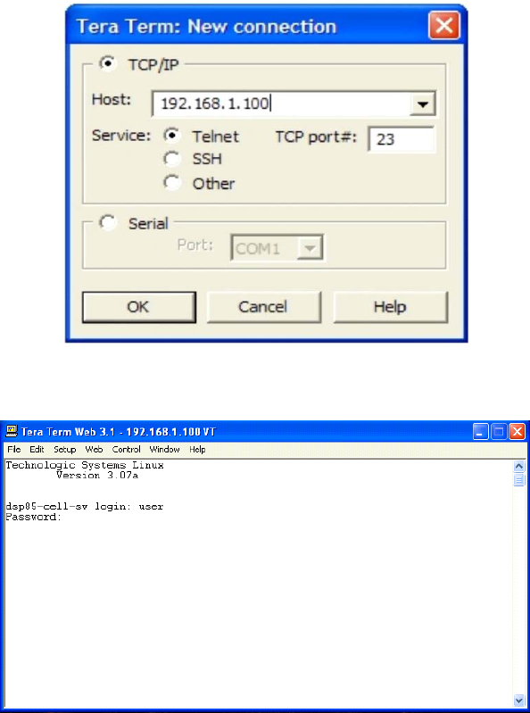
When the TeraTerm program is started, the following screen is displayed. Change the default host IP address to the IP address of the
pilot beacon to be controlled. In the case of a new install, the default address is 192.168.1.100 and has been assigned at the factory.
Select the service Telnet. The TCP Port must be 23.
Pressing the “OK” button will bring the user to the following screen, which will require the user to log in. The default user name is
“user”. The default password is “csi1234”.
In the field after the prompt “DSP85-cell-X login;” type the user name and password. After typing the password press the enter key and
the main menu will be displayed as shown in the text menu section.
Telnet and serial sessions both provide access to the same Text Menu Interface. We have already shown many of the
options available and all are self explanatory, so they will not be repeated.
-28-
Telnet Session (Remote Access):
-29-
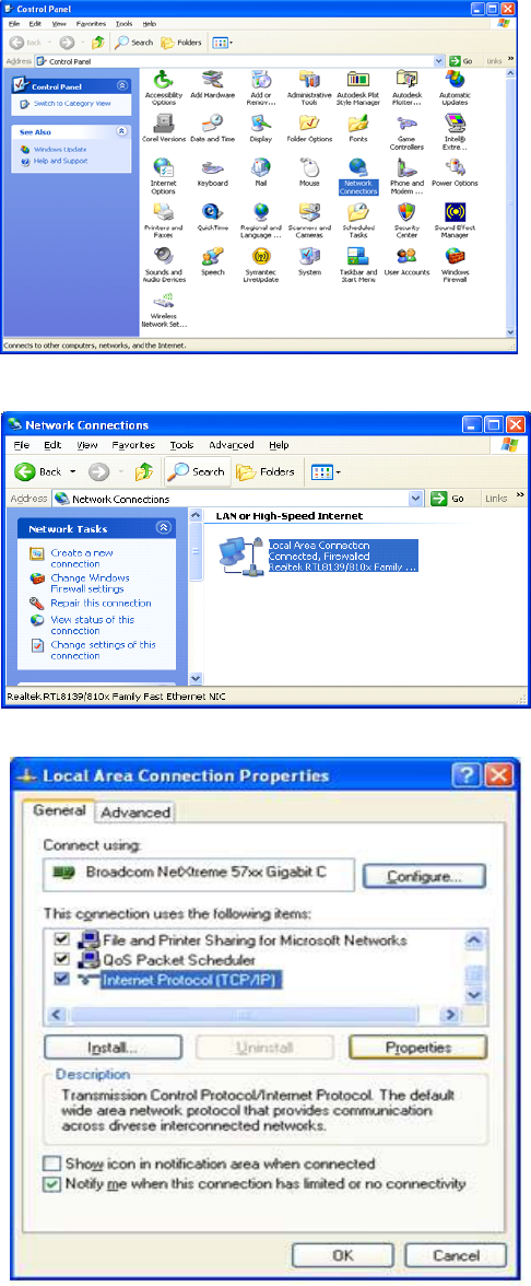
Instructions to change TCP/IP settings on your Windows computer.
Click in the Network Connections Icon in the Control Panel. See below.
Right click on Local Area Connection - and select “Properties”.
Scroll down to “Internet Protocol (TCP/IP) and click on the “Properties” button.
Additional Tips:
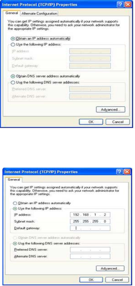
If you are set up to use DHCP, the window shown below will be displayed.
Select “Use the following IP address:” and enter “192.168.1.2.” The subnet mask should automatically populate to “255.255.255.0”.
Nothing else will need to be chosen or entered. Click “OK”, then “OK again and retry connection.
A crossover Ethernet cable (supplied) must be used for Web Interface access. As a reminder, you must verify the Ethernet port on your
laptop is powered. If your laptop is on battery power, the Ethernet port may be inactive by default. If this is the case simply plug in the
laptop to a 110vac source or change the power settings to enable the Ethernet port when the laptop is using battery power.
-30-

-31-
Seller warrants that its products are transferred rightfully and with good
title; that its products are free from any lawful security interest or other
lien or encumbrance unknown to Buyer; and that for a period of one year
from the date of installation or fifteen months from the date of original
shipment, whichever period expires first, such products will be free from
defects in material and workmanship which arise under proper and normal
use and service. Buyer’s exclusive remedy hereunder is limited to Seller’s
correction (either at its plant or at such other place as may be agreed upon
between Seller and Buyer) of such defects by repair or replacement at no
cost to Buyer. Transportation costs in connection with the return of prod-
ucts to Seller’s plant or designated facility shall be paid by Buyer. The
provisions of this warranty shall be applicable with respect to any product
which Seller replaces pursuant to it. SELLER MAKES NO WARRANTY,
EXPRESS OR IMPLIED, OTHER THAN AS SPECIFICALLY STATED ABOVE.
EXPRESSLY EXCLUDED ARE THE IMPLIED WARRANTIES OF MERCHANTABIL-
ITY AND FITNESS FOR PURPOSE. THE FOREGOING SHALL CONSTITUTE ALL
OF SELLER’S LIABILITY (EXCEPT AS TO PATENT INFRINGEMENT) WITH
RESPECT TO THE PRODUCTS. IN NO EVENT SHALL SELLER BE LIABLE FOR
SPECIAL, CONSEQUENTIAL OR INCIDENTAL DAMAGES, INSTALLATION
COSTS, LOST REVENUE OR PROFITS, OR ANY OTHER COSTS OF ANY
NATURE AS A RESULT OF THE USE OF PRODUCTS MANUFACTURED BY THE
SELLER, WHETHER USED IN ACCORDANCE WITH INSTRUCTIONS OR NOT.
UNDER NO CIRCUMSTANCES SHALL SELLER’S LIABILITY TO BUYER EXCEED
THE ACTUAL SALES PRICE OF THE PRODUCTS PROVIDED HEREUNDER. No
representative is authorized to assume for Seller any other liability in
connection with the products.
FCC: This product does not have FCC approval at the date of the printing of this manual.
One Year Limited Warranty
Industry Certifications/Registration Numbers:
-32-
Index
A
AC Current 10
AC Power Frequency 10
AC Power Specifications 10
AC Voltage 10
Acronyms and Definitions 5
Additional Tips 29
Alarm Configuration 19
B
Beacon Control 14
Box Weight 10
C
Circuit Operational Description 13, 14, 15, 16, 17, 19
Composite Transmit Power 14
D
Depth 10
E
EIA232 Pin Specifications 7
Email Configuration: 20
Environmental Requirements 10
Event Log 17
Explosive Atmospheres 4
F
FPGA Programming Alarm 19
Functional Overview: 6
G
GPS Alarm 19
Grounding 4
H
Height 10
I
Important Installation Notes 9
Industrial Dust 10
Industry Certifications/Registration Numbers 31
Install & Upload 18
Install Software 18
L
Lightning Danger 4
Limited Warranty 31
Local Communication Interface Ports 6
Local Network 13
Location Information 15
Log Configuration 21
Login 25
M
Main Menu 25
Mechanical Drawing 11
Mechanical Specifications 10
Monitoring & Alarms 7
N
Networking Configuration Menu 27
null modem adapter 22
O
Optional Accessories 9
P
Phase Lock Alarm 19
Pilot Beacon Configuration Menu 26
Pilot Beacon Per Channel Transmit Power 14
PN Offset 14
Power supply cable connectors 9
Powering Up the Unit 6
Product Introduction 5
Product Registration Information 4
Property Failure Alarm 19
R
Reboot 19
Relative Humidity 10
Remote Network 15
S
serial cable 22
Set Parameters Menu 25
Signal Transmit Enables 14
SNMP Configuration 16
Software Abort Alarm 19
Software Error Alarm 19
Surface Coating 10
System Health 17
System Set-Up Considerations 8
System Status 12
T
Tau (Delay Correction): 14
TCP/IP settings 29
Telnet Session 28
Temperature Range 10
terminal emulation programs 23
Text Menu Interface 22
Thermal Management 10
Time Synch Alarm 19
U
USB Interface 7
User Interface 25
User Maskable Alarms 19
W
Wall Mounting the Pilot Beacon 8
Warranty 31
Web based GUI Session 12
Width 10

Notes

Notes

Notes

960-1046-001 rev B ECO