Westell CSIDRACELAAWS AWS Repeater User Manual 960 1042 006 Manual John r006 indd
Westell, Inc. AWS Repeater 960 1042 006 Manual John r006 indd
Westell >
User Manual
CSI-DRACELA-PR-AW
CS12-560-419

W
A
R
N
I
N
G
:
T
h
i
s
i
s
NOT a CONSUMER device.
It
i
s
designed
for
i
n
st
a
ll
a
t
i
on
by FCC
L
I
C
EN
SEES
AND
Q
U
AL
I
F
I
ED
INSTALLERS. You MUST have an FCC
L
I
C
EN
SE
or
express consent
of
an FCC
L
i
ce
n
se
e
to
operate
t
h
i
s
device. U
n
a
u
t
ho
ri
ze
d
use may result in significant
f
o
rf
e
i
t
u
re
p
e
n
a
l
t
i
e
s,
i
n
cl
ud
i
ng
p
e
n
a
l
t
i
e
s
i
n
excess
of
$100,000
for
each
con
t
i
nu
i
ng
vi
o
l
a
t
i
on.
The Installation height of the antenna for AWS band 1700/2100 MHz operations is limited to 10 meters above ground for compliance with
FCC Regulation Section 27.50
Important Safety Information
Antennas used
for the
purpose
of radiating
signals
indoors are limited to a maximum gain of 3 dBi. The outdoor
antenna used
for
the
purpose
of
commun
i
ca
t
i
ng
to the w
i
re
l
e
ss
i
n
f
ra
st
ruct
u
re
i
s
li
mit
e
d
to -2 dBi, or any
comb
i
n
a
t
i
on
of
g
a
i
n
and
l
o
ss
that
e
qu
a
tes
to
-2 dBi at output. Each
antenna
must be
positioned
to
observe
minimum
separation requirements
from all
users
and
bystand-
ers. The following
guidelines
should be
used
when
considering
separation distances.
INDOOR
antennas
must be
placed
such that, under normal
conditions, personnel cannot
come within 20 cm (~8.0 in.) from
any
inside
antenna.
Adhering to this minimum
separation
will
ensure
that the
employee
or
bystander cannot exceed
RF
exposures
beyond
the maximum
permissible
limit
as defined
by
se
ct
i
on
1.1310
i
.
e
.
li
mit
s
for
G
e
n
e
ra
l
Po
pu
l
a
t
i
on
/
U
ncon
t
ro
ll
e
d
Exp
o
su
re
.
OUTDOOR
antenna
must be
positioned
such that, under normal
conditions, personnel cannot approach
closer than 120 cm.
(~4
ft.). A non-
d
i
re
ct
i
on
a
l
antenna
having a maximum
g
a
i
n
of
-2 dBi
i
s
used,
p
re
ca
u
t
i
on
s
sh
ou
l
d
be taken to
prevent p
e
rso
nn
e
l
f
rom
routinely
passing
closer than
specifi
e
d.
Radio and
T
e
l
e
vi
si
on
I
n
t
e
rf
e
re
n
ce
NOTE: This
equipment
has
been tested
and found to comply with the limits for a
Class
A
d
i
g
i
t
a
l
device,
pursuant
to Part 15
of t
h
e
FCC rules.
These
limits are
designed
to provide
reasonable protection against
harmful
interference
when the
equipment
is
oper-
ated in a
commercial environment.
This
equipment generates, uses
and can
radiate
radio
frequency energy
and,
if
not
installed
and used
in
accordance
with the instruction
manual,
may
cause
harmful
interference
to radio
communications. Operation
of
this
e
qu
i
p
me
n
t
i
n
a
re
sid
e
n
t
i
a
l
area
i
s
li
ke
l
y to
cause
h
a
rmf
u
l
i
n
t
e
rf
e
re
n
ce
i
n
w
h
i
ch
case
the
user
will
be
re
qu
i
re
d
to correct the
interfer-
ence
at his own
expense. Changes
and
Modifi
ca
t
i
on
s
not
expressly approved
by
C
e
ll
u
l
a
r
Sp
e
ci
a
l
t
i
e
s,
I
n
c.
can
vo
i
d
your
a
u
t
ho
ri
t
y
to
operate
this
equipment
under
Federal Communications Commission’s rules.
C
e
ll
u
l
a
r
Sp
e
ci
a
l
t
i
e
s,
I
n
c.
grants
to the
purchaser
a
fully
p
a
i
d
li
ce
n
se
,
at no
a
dd
i
t
i
on
a
l
charge,
t
o
copy or
otherwise reproduce
all or portions of the product
documentation.
Such
reproduction
shall be for
the
purchasers
use only
.

T
a
b
l
e
of
C
on
t
e
n
t
s
Se
ct
i
on
1........................................................................................................................... 5
Hardware
Confi
gu
ra
t
i
on.....................................................................................................
5
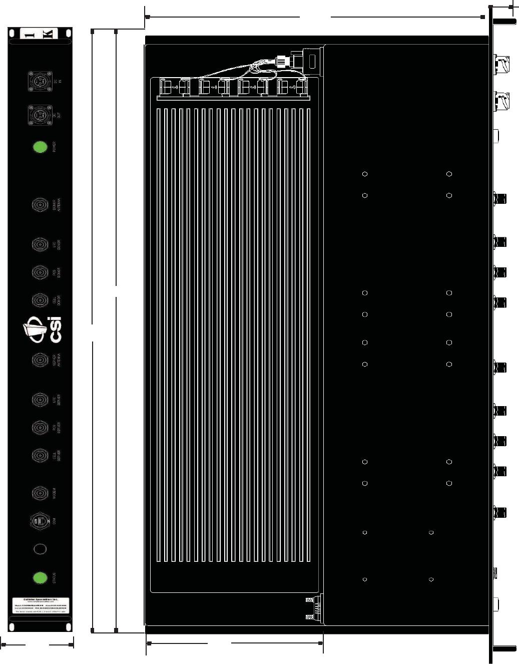
Module Side
View............................................................................................................... 5
Module
Face
Plate
View..................................................................................................... 5
Module Top
V
i
e
w
................................................................................................................
5
I
n
st
a
ll
a
t
i
on..........................................................................................................................
6
Physical
Installation Into The
T
ra
i
n....................................................................................
6
Module
Interconnection Diagram.......................................................................................
7
RF and Power
Cabling....................................................................................................... 7
Se
ct
i
on
2........................................................................................................................................ 7
Face
Plate
Dimensions...................................................................................................... 8
Top
V
i
e
w D
i
me
n
si
on
s.
........................................................................................................
9
Power
Up............................................................................................................................ 10
N
orma
l
O
p
e
ra
t
i
on...............................................................................................................
10
System Status.................................................................................................................... 10
A
l
a
rms................................................................................................................................
10
Alarm
Notifi
ca
t
i
on
Message............................................................................................... 10
Hardware Operations......................................................................................................... 11
Test
Po
i
n
t
L
o
ca
t
i
on
s
and
V
a
l
u
e
s.
.......................................................................................
11
I
nd
i
ca
t
o
r
L
i
gh
t
s.
..................................................................................................................
11
T
ro
ub
l
e
sh
oo
t
i
ng..................................................................................................................
11
Se
ct
i
on
3.........................................................................................................................................11
Warranty and
R
e
p
a
i
r
Procedures....................................................................................... 13
Local
Communication Interface
Ports.................................................................................
16
EIA232 Pin
Specifi
ca
t
i
on
s.
..................................................................................................16
General Operation Overview.............................................................................................. 16
Se
ct
i
on
4........................................................................................................................... 16
Ethernet.............................................................................................................................. 17
Monitoring
&
Alarms........................................................................................................... 17
Text Menu
I
n
t
e
rf
a
ce
............................................................................................................
17
Local
Access.......................................................................................................................
17
F
i
gu
re
1...............................................................................................................................17
F
i
gu
re
2...............................................................................................................................17
L
og
i
n...................................................................................................................................
19
Ma
i
n
Menu.......................................................................................................................... 19
Set
Parameters
Menu.........................................................................................................
19
T
e
l
n
e
t
Session
T
C
P/
I
P
........................................................................................................
20
Maintenance Mode............................................................................................................. 39
Terms
used
i
n
t
h
i
s
ma
nu
a
l
..................................................................................................
40
-4-
Section 1
Hardware Confi
gu
r
a
ti
on
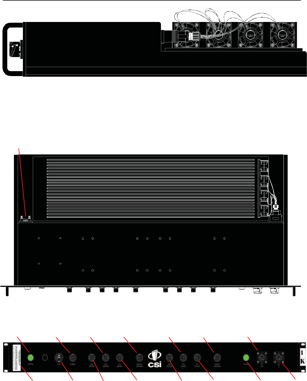
Module Side
V
iew
Warning:
The
p
ro
t
e
ct
i
ve
cover
for
the
se
ri
a
l
port must be
se
cu
re
l
y
f
a
st
e
n
e
d
when the port
i
s
not
i
n
use
to
prevent comp
ro
mi
se
of
enclosure
integrity
.
Serial
Port
Module
Top
V
i
e
w
Status
LED
Modem
PCS
Server
Server
Ant PCS
Donor
Donor Ant DC
Out
FCC
Label
COM Cell
Server
U7C
Server
Cell
Donor
U7C
Donor
Power LED DC In
Module Face Plate
V
iew
- 5 -
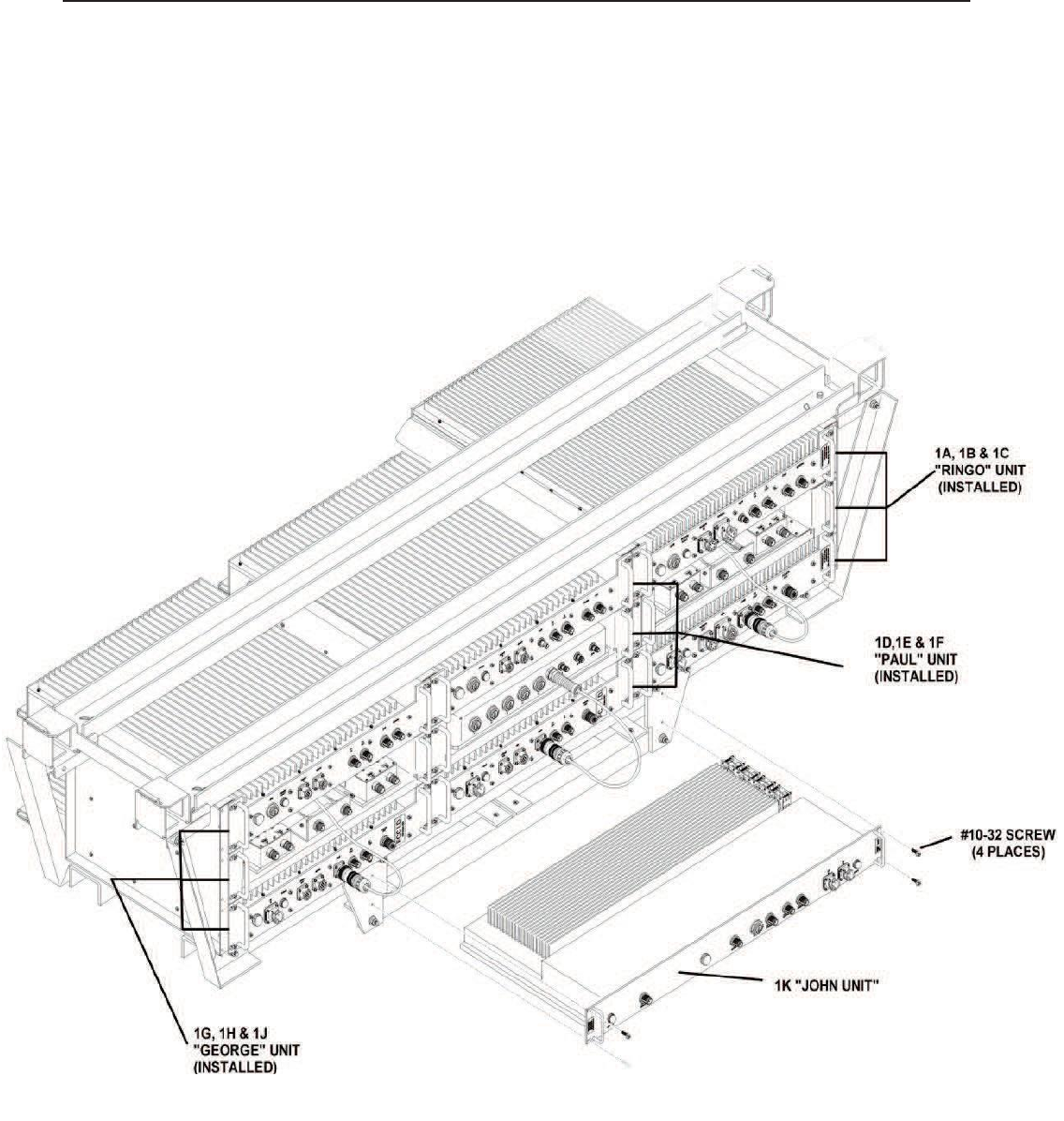
Section 1
Installation
1. Unpack the box containing the CSI 1K
repeater system module.
2.
A
f
t
e
r
unpacking
the
components,
verify
a
ll
parts
and
ca
b
l
e
s
are
present.
If
any
parts
are
d
i
sco
ve
re
d
to be missing
contact C
e
ll
ular
Specialties,
Inc. at
1-877-844-4274
to
arrange
for
replacements
to be sent. Note: all
supplied cables
are fire
resistant,
l
o
w
h
a
l
og
e
n.
3.
I
n
st
a
ll
the
repeater
i
n
the new rack
attached
at bottom
of
the
e
xi
st
i
ng
system
f
rame
and
secure
i
n
p
l
a
ce
w
i
t
h
4 - #10-32
screws .
Physical Installation
Into The
T
rain
-6 -

Section 2
Installation
1.
Remove
the male input
connector
of the CBL/A 72VDC PIGTAIL,
820-2164-001,
from the
train’s
72VDC power supply cable
and
connect
it to the female DC OUT
connector
on the 1K module. The other
connectors
on this cable
assembly
will
remain installed in
their
current
locations.
Install the
connector
of the 72VDC power supply cable from the train into the port
labeled
DC IN on the 1K
unit.
2.
Remove
the
train’s
donor
antenna
feed cable from the COMMON port on the 1B module and
connect
it to the port
labeled DONOR
ANTENNA on the 1K
module.
3.
Remove
the
train’s
radiax cable feed from the
second
COMMON port on the 1B module and
connect
it to the port
labeled
SER
VER
ANTENNA port on the 1K
module.
4.
Remove
the
820-2064-001
cable that
connects
the right hand coupler port
labeled
LOW on the 1H module to the DONOR ANT port
on
the
1J module.
5. Install the
supplied Rubber
Duck
antenna
in the 1K module, MODEM
port.
6.
Remove
the
820-2064-001
cable that
connects
the right hand coupler port
labeled
HIGH on the 1B module to the DONOR ANT
port
on the 1C
module.
7.
Remove
the
CS54-3059-12
cable that
connects
the right hand coupler port
labeled
HIGH on the 1H module to the DONOR ANT
port
on the 1F
module.
8.
Remove
the
820-2124-001
cable that
connects
the left hand coupler port
labeled
LOW on the 1H module to the DAS port on the
1
G
module.
9.
Remove
the
820-2124-001
cable that
connects
the left hand coupler port
labeled
HIGH on the 1B module to the DAS port on the
1
A
module.
10.
Remove
the
CS54-3059-12
cable that
connects
the left hand coupler port
labeled
HIGH on the 1H module to the DAS port on the
1
D
module.
11.
Remove
the
CS54-3154-12
cable that
connects
the left hand coupler port
labeled
COMMON on the 1H module to the left hand
cou-
pler port
labeled
LOW on the 1B
module.
12.
Remove
the
CS54-3154-12
cable that
connects
the right hand coupler port
labeled
COMMON on the 1H module to the right
hand
coupler port
labeled
LOW on the 1B
module.
13.
Connect
one
supplied 820-2124-036
cable from the DAS port on the 1G module to the U7C SERVER port on the 1K
module.
14.
Connect
one
supplied 820-2124-036
cable from the DONOR ANT port on the
1J
module to the U7C DONOR port on the 1K
module.
15.
Connect
one
supplied 820-2194-001
cable from the port 5 on the 1E module to the COM port on the 1K
module.
16.
Connect
one
supplied 820-2124-036
cable from the DAS port on the 1D module to the CELL SERVER port on the 1K
module.
17.
Connect
one
supplied 820-2124-036
cable from the DAS port on the 1A module to the PCS SERVER port on the 1K
module.
18.
Connect
one
supplied 820-2124-036
cable from the DONOR ANT port on the 1F module to the CELL DONOR port on the 1K
mod-
ule.
19.
Connect
one
supplied 820-2124-036
cable from the DONOR ANT port on the 1C module to the PCS DONOR port on the 1K
module.
RF
and Power Cabling
- 7-
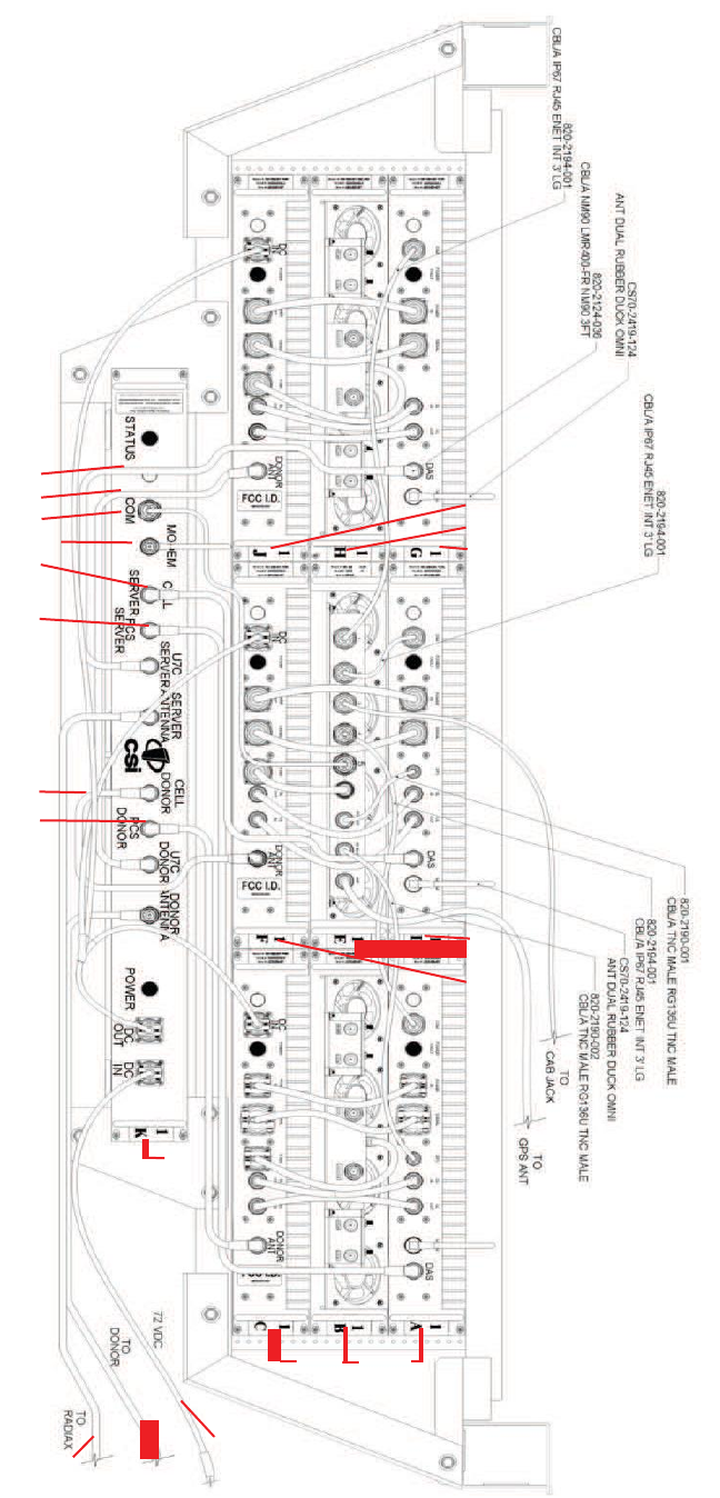
Section 2
Step
13
Step 14
1
J
Step 15
1
H
Step 5
1
G
Step
16
Step
17
Step
18
Step
19
1
D
1E
1F
1
K
1C 1B
1
A
Step
3
Step
2
Step
1
72 VDC
To
R
a
d
i
a
x To D
ono
r
Module Interconnection Diagram
- 8 -
Section 2
3.41
33.58
34.58
9.28
18.06
1.29
Face Plate Dimensions
Top View D
i
m
e
n
s
i
on
s
- 9 -

Installation
Power Up
Section 2
To power up the CSI
repeater
simp
l
y
connect
the 72 VDC power
ca
b
l
e
f
rom
the
t
ra
i
n
to the DC IN port on the Power Module.
W
h
e
n
powered
up, the
repeater
will
b
e
g
i
n
i
n
the
O
p
e
ra
t
i
on
a
l
Mode, using the
“
Band
Switching Algorithm”. The
repeater
will
not key until
boot
up is
complete,
a GPS location fix
i
s
ob
t
a
i
n
e
d
and the
un
i
t
i
s
w
i
t
h
i
n
an
”
Area D
e
fi
n
i
t
i
on
”.
Normal
Operation
After boot up and a GPS position fix
i
s
ob
t
a
i
n
the
repeater
will
b
e
g
i
n
op
e
ra
t
i
on
based
on the Area D
e
fi
n
i
t
i
on
s,
“C
h
a
nn
e
l
Power
Me
a
su
re
-
ment and Keying Decision” and “Low Isolation
Detection
and Protection”
algorithms.
The
operational software
will
continuously monitor
the
repeater
’
s
environment
and make the
necessary
a
d
j
u
st
me
n
t
s
to keep the product
op
e
ra
t
i
ng
w
i
t
h
i
n
sp
e
ci
fi
ca
t
i
on
s
and FCC
T
yp
e
Certifi
ca
t
i
on.
System Status
The
Software provides
real time
status
data reporting the
state
of the
repeater.
This
status contains:
System Info:
L
o
ca
t
i
on
Mo
d
e
l
Board
T
yp
e
C
a
rri
e
r
SW
V
e
rsi
on
Se
ri
a
l
N
umb
e
r
I
t
e
m
N
umb
e
r
Date
Bu
il
t
Watchdog
T
i
me
r
CPLD
V
e
rsi
on
Software
Build
Information:
Bu
il
d
e
r
URL
R
e
vi
sion
Comp
il
e
D
a
t
e
Local
Area
network:
Hostname
Boot
Pro
t
oco
l
I
P
A
dd
re
ss
MAC
A
dd
re
ss
Wide Area
n
e
tw
o
r
k
:
Remote
En
a
b
l
e
d
Modem
T
yp
e
I
P
A
dd
re
ss
SNMP
Confi
gu
r
a
ti
on:
En
a
b
l
e
d
R
ea
d
-o
n
l
y U
se
r
Read-write U
se
r
R
ea
d
-o
n
l
y U
se
r
R
ea
d
-o
n
l
y
Commun
i
t
y
Read-write Commun
i
t
y
T
ra
p
s/
I
n
f
orms
H
ea
rt
b
ea
t
Modem
Status:
Conn
e
ct
e
d
GPS
Location Data:
Run
St
a
t
e
L
a
t
i
t
ud
e
L
ong
i
t
ud
e
PCS
F
il
t
e
r
I
D
L
o
ca
t
i
on
BTA
Sa
t
e
lli
t
e
Coun
t
No Box
Coun
t
Se
a
rch
i
ng
Coun
t
RF
Alarms:
Over
R
a
ng
e
O
sci
ll
a
t
i
on
VSW
R
Out
if
Band
O
ve
rd
ri
ve
Low
Si
gn
a
l
No
Si
gn
a
l
Scan Receiver:
Run
St
a
t
e
Dekey
L
i
mit
F
il
t
e
r
I
D
Ch
a
nn
e
l
s
Ch
a
nn
e
l
-1
Ch
a
nn
e
l
-2
Ch
a
nn
e
l
-3
Ch
a
nn
e
l
-4
Ch
a
nn
e
l
-5
System Alarms:
Syn
t
h
e
si
ze
r
V
o
l
t
a
g
e
T
e
mp
e
ra
t
u
re
So
f
t
w
a
re
H
a
rd
w
a
re
Alarms
The
Operating Software
will
monitor the
repeater
for
conditions
that are out of normal
operation,
triggering an alarm event. The
Operat-
ing
software
in
conjunction
with the
Communications Subsystem
when so
configured
will
send
a
l
a
rm
messages
via
E-ma
il
or SMS
t
e
xt
i
ng
to a User
Provisioned
account.
Each Alarm has
these
User
Provisioned Capabilities.:
· D
i
sa
b
l
e
the
System:
The
O
p
e
ra
t
i
ng
so
f
t
w
a
re
can
d
i
sa
b
l
e
the
System
(pro
h
i
b
i
t
Keying)
un
t
il
the
a
l
a
rm
cond
i
t
i
on
i
s
cleared
i
f
provisioned
·
A
l
a
rm
F
il
t
e
r
Cond
i
t
i
on
s:
A
F
il
t
e
r
Cond
i
t
i
on
(such
as
X
number
of
occurrences
per hour) to the
a
l
a
rm
to
prevent
f
a
l
se
or
un
-
useful notifi
ca
t
i
on
s
if
p
ro
vi
sion
e
d.
·
Send
an
A
l
a
rm
Message:
The
O
p
e
ra
t
i
ng
So
f
t
w
a
re
can
send
a
no
t
i
fi
ca
t
i
on
via
message
E-ma
il
or SMS through the
Commun
i
-
cations Subsystem
if
provisioned.
·
A
l
a
rm
C
l
ea
r
Message:
The
O
p
e
ra
t
i
ng
So
f
t
w
a
re
can
send
an
a
l
a
rm
clear
message
when an
a
l
a
rm
cond
i
t
i
on
clears
if
p
ro
vi
-
sioned.
Alarm
Notification
Me
ss
a
g
e
The alarm
messages consists
of the
Systems
Identifi
ca
t
i
on
Tag, a
summary
of
the current
a
l
a
rms,
and a short
Eng
li
sh
message describ-
ing the alarm
condition(s).
Below is a list of the
alarms
that
will
trigger an alarm
message
to be
sent.:
Downlink
Over
Range
Downlink
High
T
e
m
p
e
r
a
tu
r
e
Scan Receiver
L
o
w
U
n
ca
li
b
r
a
ti
on
Uplink Over
Range
Downlink
Low
T
e
m
p
e
r
a
tu
r
e
Scan Receiver H
i
gh
AGC D
i
s
a
b
l
e
d
Synthesizer Error
Uplink High
V
SWR
No GPS D
a
ta
Property
File
Er
r
o
r
DAC
Error
Uplink Low
V
SWR
No GPS
L
o
c
k
DAS
F
a
il
u
r
e
DC
Current High
Uplink Filter
L
o
a
d
No GPS
F
i
x
Watchdog
Ti
m
e
r
DC
Current Low
Uplink Over
C
u
rr
e
n
t
GPS
Antenna
C
u
rr
e
n
t
Modem
Not
R
e
s
pond
i
ng
Downlink
High VSWR
Uplink
Under
C
u
rr
e
n
t
GPS Fix Filter Not
Pr
e
s
e
n
t
User
L
og
i
n
Downlink
Low VSWR
O
s
c
ill
a
ti
on
C
h
a
ss
i
s
O
v
e
r
h
ea
t
Password
C
h
a
ng
e
d
Downlink
Filter
Load
Uplink High
T
e
m
p
e
r
a
tu
r
e
C
h
a
ss
i
s
Under
T
e
m
p
CPU
B
oo
t
Downlink
Over
Current
Uplink Low
T
e
m
p
e
r
a
tu
r
e
Software A
bo
rt
Placed
in
Disabled
C
ond
i
ti
on
Downlink
Under Current
Fan
F
a
il
u
r
e
Software
Er
r
o
r
I
n
Maintenance
Mo
d
e
Powerup and System Check
Out
Procedure
s
- 10 -

Hardware
Operations
T
e
s
t
Point
L
o
ca
ti
on
s
and
V
a
l
u
e
s
Section 3
The CSI
repeater, CS12-560-419,
by
design, has
no
e
xt
e
rn
a
l
test
po
i
n
t
s.
The
modu
l
e
i
s
se
a
l
e
d
w
i
t
h
no
user
se
rvi
ce
a
b
l
e
parts
i
nsid
e
.
T
e
st
i
ng
and
con
fi
gu
ra
t
i
on
i
s
done
e
xcl
usive
l
y by
i
n
t
e
rf
a
ci
ng
the
repeater w
i
t
h
a
l
a
p
t
op
or
desktop computer
and using Text Menu
I
n
t
e
rf
a
ce
(TMI).
T
h
i
s
user
i
n
t
e
rf
a
ce
will
provide a
comp
l
e
t
e
status
of
the
repeater.
In
most
cases
if
a
ll
other
components
of
the
system
prove to
b
e
working properly and the
repeater
is not, the user
will
need
to return the unit to CSI for
inspection
and repair.
See
the Warranty and
R
e
p
a
i
r
Procedures
in
Section
3 of this
manual.
If
the cover for module is
removed
by the user the warranty
will
be void and the cost of any
needed
repair
will
be the
responsibility
of the
user
.
Indicator Lights
T
h
i
s
repeater was designed w
i
t
h
on
l
y two
e
xt
e
rn
a
l
i
nd
i
ca
t
o
r
li
gh
t
s.
Both are
a
pp
ro
xi
ma
t
e
l
y
3
/
4
”
d
i
a
me
t
e
r LEDs.
L
o
ca
t
e
d
on the
Module
face plate. The first LED
l
a
b
e
l
e
d
STATUS
g
l
o
w
s
red
as
the
repeater
i
s
powered
up. When the
un
i
t
comp
l
e
t
e
s
a
ll
of
i
t
’
s
bootup
p
ro
ce
du
re
s
the LED
will
change
color and glow
green
to indicate the
system
is
operating
normally.
If
the LED
remains
red
it’
s
an indication of a
prob-
lem and the user
will
need
to check the
system status
using the TMI.
The
second
LED is also
located
on the
faceplate
of the Module, and is
labeled
POWER. This light is
designed
only to show that the unit
has DC current and
will
glow
green
when the unit is
powered.
T
r
oub
l
e
s
hoo
ti
ng
All
cables
should be
checked
for
shorts
and
opens.
The rooftop
antenna
(Donor
Antenna),
should be
checked
for
damage.
The DAS
antennas
should be
checked
for
damage.
If
cables
and
antennas
are
acceptable
and the problem
persists,
check
repeater status
using the Web
based
GUI or the TMI.
See Alarm/
Action Matrix on the next
page.
Sh
ou
l
d
the
repeater
f
a
il
,
or
if
service
i
s
l
o
st
and the
cause
can not be
determined
f
rom
the
steps above,
the
user sh
ou
l
d
contact CSI
T
e
chn
i
ca
l
Support
@
1.877.844.4274.
CSI
will
re
mo
t
e
l
y
access
the
repeater
and
a
d
vi
se
the
respondent
of
next
st
e
p(s).
-11 -

Hardware Operations
Section 3
Subsystem
Alarm
Name
Alarm
T
y
p
e
Send
E-m
a
il
Shutdown
Op Mo
d
e
?
Disable
U
n
i
t?
Downlink
Power
Uplink
Power
Common Hardware Alarms
Downlink
P
A
Uplink
P
A
Scanning Receiver Alarms
GPS
Receiver Alarms
Software
Alarm
T
ypes
Communications
Over
Range
Low
Si
gn
a
l
No
Si
gn
a
l
Out
of
Band
Si
gn
a
l
Over
Range
Out
of
Band
Si
gn
a
l
Synthesizer Error
Dac
Erro
r
DC Current H
i
gh
DC Current Low
Oscillation
I
npu
t
Power H
i
gh
H
i
gh
VSW
R
Low VSW
R
F
il
t
e
rL
o
a
d
O
ve
rcu
rren
t
U
nd
e
rcu
rren
t
Low
Isolation
High
T
e
mp
e
ra
t
u
re
Low
T
e
mp
e
ra
t
u
re
HighVSWR
Low VSW
R
F
il
t
e
rL
o
a
d
O
ve
rcu
rren
t
U
nd
e
rcu
rren
t
O
sci
ll
a
t
i
on
Low
Isolation
High
T
e
mp
e
ra
t
u
re
Low
T
e
mp
e
ra
t
u
re
Fan Activation
Fan
F
a
il
u
re
ScanRcvrLow
Sca
n
R
cvrH
i
gh
No GPS
Data
No GPS
L
o
ck
No GSP
F
i
x
Gps
Antenna Current
Gps
F
i
x
F
il
t
e
r Not
Pre
se
n
t
Overheat
U
nd
e
rt
e
mp
So
f
t
w
a
re
A
bo
rt
So
f
t
w
a
re
Erro
r
U
n
ca
li
b
ra
t
i
on
AGC D
i
sa
b
l
e
d
Property F
il
e
Erro
r
DAS
F
a
il
u
re
Watchdog
T
i
me
r
H
ea
rt
b
ea
t
Modem Not
Responding
Modem Not
C
onn
e
ct
e
d
Critical
R
ou
t
i
n
e
R
ou
t
i
n
e
R
ou
t
i
n
e
Critical
R
ou
t
i
n
e
Critical
C
ri
t
i
ca
l
Se
ve
re
Se
ve
re
Routine
R
ou
t
i
n
e
Se
ve
re
Se
ve
re
C
ri
t
i
ca
l
Se
ve
re
Se
ve
re
Routine
Se
ve
re
Se
ve
re
Severe
Se
ve
re
C
ri
t
i
ca
l
Se
ve
re
Se
ve
re
R
ou
t
i
n
e
Routine
Se
ve
re
Se
ve
re
Routine
Se
ve
re
Severe
Se
ve
re
Critical
Se
ve
re
C
ri
t
i
ca
l
Severe
Se
ve
re
Severe
Se
ve
re
C
ri
t
i
ca
l
Se
ve
re
C
ri
t
i
ca
l
C
ri
t
i
ca
l
C
ri
t
i
ca
l
C
ri
t
i
ca
l
C
ri
t
i
ca
l
I
n
f
orma
t
i
on
a
l
Severe
R
ou
t
i
n
e
Y
e
s
N
o
N
o
N
o
Y
e
s
N
o
Y
e
s
Y
e
s
Y
e
s
Y
e
s
No
N
o
Y
e
s
Y
e
s
Y
e
s
Y
e
s
Y
e
s
No
Y
e
s
Y
e
s
Y
e
s
Y
e
s
Y
e
s
Y
e
s
Y
e
s
N
o
No
Y
e
s
Y
e
s
No
Y
e
s
Y
e
s
Y
e
s
Y
e
s
Y
e
s
Y
e
s
Y
e
s
Y
e
s
Y
e
s
Y
e
s
Y
e
s
Y
e
s
Y
e
s
Y
e
s
Y
e
s
Y
e
s
Y
e
s
N
o
Y
e
s
N
o
Y
e
s
N
o
N
o
N
o
Y
e
s
N
o
Y
e
s
Y
e
s
Y
e
s
Y
e
s
No
N
o
N
o
N
o
Y
e
s
N
o
N
o
No
Y
e
s
N
o
N
o
N
o
Y
e
s
N
o
N
o
N
o
No
Y
e
s
N
o
No
N
o
Y
e
s
Y
e
s
Y
e
s
N
o
Y
e
s
N
o
Y
e
s
N
o
N
o
Y
e
s
Y
e
s
Y
e
s
Y
e
s
Y
e
s
Y
e
s
Y
e
s
Y
e
s
N
o
N
o
N
o
N
o
N
o
N
o
N
o
N
o
Y
e
s
Y
e
s
N
o
N
o
N
o
N
o
N
o
N
o
N
o
N
o
N
o
N
o
N
o
N
o
N
o
N
o
N
o
N
o
N
o
N
o
N
o
N
o
N
o
N
o
N
o
N
o
N
o
Y
e
s
N
o
N
o
N
o
Y
e
s
N
o
N
o
??
N
o
Y
e
s
Y
e
s
N
o
N
o
N
o
N
o
N
o
N
o
-12-

Hardware
Operations
Section 3
1
Scope
The warranty period for this product shall be 18
months
(548
calendar
days) from the date of the
Purchaser
’
s
A
cce
p
t
a
n
ce
,
plus
any
extended maintenance periods as specified
i
n
the order. During
sa
i
d
period(s),
CSI
warrants
that
each repeater w
ill
be free of
defects
in material and
workmanship.
CSI’s
sole obligation and the
Purchaser
’
s
exclusive remedy
for
any
breach
of
warranty
i
s
li
mit
e
d
to
a
d
j
u
st
me
n
t
s,
re
p
a
i
rs,
or
a
t
the
Purchaser
’
s
op
t
i
on,
re
p
l
a
ce
me
n
t
of
a
System
or
parts
of
a
System
t
h
e
re
o
f
at no cost to the CSI.
All
exchanged Syst
e
ms
or
System
parts
will
become
the property of the CSI. Servicing
hereunder
will
be
furnished
by the
CSI’s nearest service loca-
tion. CSI shall perform this
service
at a time
agreed
to by the
Purchaser.
This warranty
will
not apply to a particular item if:
(a)
Adjustment,
repair or
replacement
is
required because
of
accident, neglect, misuse,
failure of electric power,
environmen-
tal controls,
transportation
or
causes
other than ordinary
use, except
that such
adjustment,
repair, or
replacement
is
required
due to
actions caused
by or the
responsibility
of
CSI’s employees
or
CSI’s authorized
agents;
(b) The
Purchaser
fails to
operate
a
System
or follow
operator-level maintenance procedures
in
accordance
with the CSI’
s
recommendations;
(c) Any
person
other than the
CSI’s engineer
or an
authorized agent
of the CSI modifies,
a
d
j
u
st
s,
or
re
p
a
i
rs
the product
o
r
performs
any
maintenance service
other than routine
operator-level maintenance
without the
CSI’s
prior written
consent.
The warranty
hereunder does
not
include:
(a) Any
furnished consumable supplies,
(b) Painting or
refi
n
i
sh
i
ng
the
p
ro
du
ct
,
(c) Electrical work
external
to the
product,
(d)
I
n
st
a
ll
a
t
i
on,
ma
i
n
t
e
n
a
n
ce
or
re
mova
l
of
a
l
t
e
ra
t
i
on
s
or
attachments
to the product
except as
provided by the
o
ri
g
i
n
a
l
syst
e
m
design.
CSI’s
liability for
breach
of the
above
warranty
will
in no event
exceed
the
purchase
price of the
Product(s)
that has
been paid
by the
Purchaser
.
2
Product
Hardware Warranty
(Non-Software)
(a) CSI
represents
and
warrants
to the
Purchaser
that upon delivery of a
repeater
to the
Purchaser,
all right, title and
interest
i
n
the
un
i
t
will
pass
to the
Purchaser
f
re
e
of
a
ll
li
e
n
s,
i
mp
e
rf
e
ct
i
on
s
i
n
t
i
t
l
e
,
cl
a
i
ms,
charges,
re
st
ri
ct
i
on
s,
or other
e
ncumbranc-
es. The CSI
represents
and
warrants
a
repeater
’
s
Hardware
(sp
e
ci
fi
ca
ll
y
e
xcl
ud
i
ng
the
Product
So
f
t
w
a
re
)
as
f
u
rn
i
sh
e
d
sh
a
ll
be new,
merchantable,
free from
defects
in material and
workmanship,
fit
for
the
o
rd
i
n
a
ry
purpose
for w
h
i
ch
the product
i
s
used,
shall not infringe on any U.S.
Patent,
and for the period
specified
i
n
t
h
i
s
document
f
rom
the date a
repeater
i
s
d
e
li
ve
re
d
and shall conform to this
documents
specifi
ca
t
i
on
s.
Sh
ou
l
d
a
un
i
t
not
con
f
o
rm
to the
f
o
re
go
i
ng
w
a
rran
t
i
e
s,
CSI
sh
a
ll
re
p
a
i
r
o
r
replace defective
or
nonconforming product.
(b) During the warranty period, a
d
e
f
e
ct
i
ve
repeater sh
a
ll
be
e
i
t
h
e
r
re
p
a
i
re
d
on-site by CSI or
returned
to the CSI
for
re
p
a
i
r
or
replacement
at no
charge
or cost to the
Purchaser.
The
Purchaser
shall bear the risk of loss or
damage
until a unit is
placed
in the
possession
of the carrier.
Unless otherwise agreed
to by the CSI and the
Purchaser,
for a product that is
returned to
CSI for repair, CSI shall
complete repairs
and return
repaired
the product, or ship a
replacement
product, within three
(3)
days
of receipt of
defective repeater
at
CSI’s designated
repair location. CSI shall bear the cost of
transportation
charges
for
shipment
to CSI (FOB origin freight collect) of the product to be
repaired
or
replaced.
For return
shipments
from CSI
to
the
Purchaser,
CSI shall bear the risk of loss or
damage
during transit and shall
prepay
and bear the cost of
transportation
charges
for
shipment
of the product that has
been repaired
or
replaced.
If
a
repeater returned
is not
defective,
CSI
shall
promptly
advise
the
Purchaser
in writing of the
determination
and in such
cases,
CSI shall return product to the
Purchaser
at the
Purchaser
’
s
expense
and risk
i
n
i
t
s
“as
re
ce
i
ved
”
cond
i
t
i
on.
If
a
repeater
i
s
returned
and
i
s
not
i
n
warranty,
CSI
sh
a
ll
promptly
advise
the
Purchaser
in writing of this
determination
and the
charge
to repair the product. In such
cases,
CSI
shall
repair the product
if
so
instructed
by the
Purchaser
in writing and
charge
the
Purchaser
for labor, parts, and
shipping.
(c) During the warranty period,
if
the
Purchaser
’
s
t
e
chn
i
ca
l
p
e
rso
nn
e
l
attempt
to
determine whether
or not a CSI
repeater
i
s
the
cause
of
service
interruption and
cannot
identify and
resolve
the problem
causing
the interruption after
communicating
with
CSI’s technical personnel
via
telephone
or other
suitable means,
and the
service
interruption still
exists,
then the
Pur-
chaser
may
request
that CSI begin on-site
repairs as
soon
as possible,
but in no event later than one (1)
business
day
plus
reasonable
travel time after receiving the
Purchaser
’
s
request.
If
the
p
ro
b
l
e
m
i
s
w
i
t
h
C
SI
’
s
product,
(so
f
t
w
a
re
or
h
a
rd
w
a
re
),
such on-site
repairs
by CSI shall be at no
charge
to the
Purchaser
.
Warranty and Repair Pr
o
ce
du
r
e
s
- 13 -

Section 3
Hardware
Operations
(d) During the Warranty period,
if
the
service
interruption still exists after
compliance
with (c)
above,
and the
service interrup-
tion is
caused
by either
CSI’s defective repeater(s)
and/or
CSI’s
product that
does
not confirm to
sp
e
ci
fi
ca
t
i
on
and CSI
h
a
s
been
given a
reasonable
time frame,
as determined
by the
Purchaser,
to correct the
service
interruption, the
Purchaser may
return the product to CSI and
receive
a credit for the total
purchase
price of the
Product
or a
completely
new
repeater,
at
the
Purchaser
’
s
op
t
i
on,.
(e) Any
replacement,
repair, modifi
ca
t
i
on,
i
n
st
a
ll
a
t
i
on
or other
service performed
by CSI
sh
a
ll
be
warranted, commencing w
i
t
h
the date upon which
repaired
product is
returned
to the
Purchaser,
for the
remainder
of the
unexpired
period of the
warranty
.
(f) The
warranties
do not
extend
to a
repeater
to the extent that such
repeater
has
been subjected
to
misuse, neglect,
abuse,
accident caused
by the
Purchaser
or by a
t
h
i
rd
party
subsequent
to the
d
e
li
ve
ry
of
the
un
i
t
,
and such
a
ct
i
on
i
s
the
cause
of t
h
e
damage
or
malfunction.
3
Product
Software
W
arranty
(a) CSI
warrants
that the
Purchaser
shall have quiet
enjoyment
of the
Product Software
and that the
Product Software
and
the
Purchaser
’
s
use
sh
a
ll
be
f
re
e
f
rom
cl
a
i
ms
of
i
n
f
ri
ng
e
me
n
t
,
misuse
or
mi
sa
pp
ro
p
ri
a
t
i
on
of
any
i
n
t
e
ll
e
ct
u
a
l
property
ri
gh
t
during the term of the
Purchaser license
to Use the
Software.
As to
Product Software
which CSI
does
not have title, CSI
war-
rants that has rights in the
Software
sufficient to permit the
li
ce
n
se
of
the
So
f
t
w
a
re
to and that CSI
has
full
right, power
a
nd
authority to
license
the
Software
and other rights
granted hereunder
to Verizon
Wireless.
(b) CSI also
warrants
that the media containing the
Software
will
be free from
defects
in material and
workmanship
and
that
all
related services
provided by CSI shall be
rendered
by qualified
p
e
rso
nn
e
l
who
will
perform the
tasks assigned
consi
st
e
n
t
with good
professional practice
and the
state
of the art
involved.
(c) CSI also
warrants
that there
does
not exists a copy
protection
or similar
mechanisms
within the
Product Software, which
will,
either now or in the future, interfere with the
operation
of the
Product. Furthermore,
CSI
warrants unless requested
in
writing by the
Purchaser
and the
Purchaser approves response,
or CSI
advises
the
Purchaser
in writing that it is
necessary to
perform valid duties under this
attachment
and
authorized
in writing by the
Purchaser,
any
Product Software
provided to
the
Purchaser
by CSI for Use by the CSI or the
Purchaser shall:
·
con
t
a
i
n
no
h
i
dd
e
n
fi
l
e
s;
· not
re
p
li
ca
t
e
,
transmit or
a
ct
i
va
t
e
i
t
se
l
f
w
i
t
hou
t
con
t
ro
l
of
an
of
an
a
u
t
ho
ri
ze
d
person
op
e
ra
t
i
ng
computer
e
qu
i
p
me
n
t
on
which it
resides;
· not
a
l
t
e
r
,
damage
or
erase
any data or
computer programs w
i
t
hou
t
con
t
ro
l
of
an
a
u
t
ho
ri
ze
d
person
op
e
ra
t
i
ng
compu
t
e
r
equipment
on which it
resides;
·
con
t
a
i
n
no
encrypted
i
mb
e
dd
e
d
key, node
l
o
ck,
t
i
me
-o
u
t
or other
f
un
ct
i
on,
whether
i
mp
l
e
me
n
t
e
d
by
e
l
e
ctro
n
i
c,
me
ch
a
n
i
-
cal or other
means,
which
restricts
or may restrict Use or
access
to any
programs
or data
developed
under this
Agree-
ment,
based
on
residency
on a specific
hardware con
fi
gu
ra
t
i
on,
f
re
qu
e
n
cy
of
du
ra
t
i
on
of
Use,
or other
li
mit
i
ng
cri
t
e
ri
a
(“Illicit
Code”).
(d) Where the
Product Software
is
intended
to be
used
in
transaction processing
or in the public
switched
network, CSI
rep-
resents
that nothing in the
Product Software precludes
the
Purchaser
form
integrating
a network
management
so
l
u
t
i
on
(i
n
cl
ud
-
ing
transaction processing
and network monitoring) with the
Product Software.
(e) For the period
specified b
e
g
i
nn
i
ng
w
i
t
h
the
e
ff
e
ct
i
ve
date
of
li
ce
n
se
of
the
So
f
t
w
a
re
,
CSI
represents
and
warrants
that
t
h
e
Product Software
will
perform in
accordance
with
specifi
ca
t
i
on
s.
If w
i
t
h
i
n
one year (365 days)
subsequent
to the
e
xp
i
ra
t
i
on
o
f
the warranty period CSI has not
repaired
the
Product Software
to perform in
accordance
with
specifi
ca
t
i
on
for
any
e
xce
p
t
i
on
communicated
in writing by the
Purchaser
to CSI during the warranty period, the
Purchaser
may order and CSI shall refund
to
the
Purchaser
the
amount
paid to it for the
nonconforming Product Software.
(f) CSI
represents
and
warrants
that
if
any
po
rt
i
on
of
the
Product
So
f
t
w
a
re
i
s
or
becomes
unu
sa
b
l
e
,
t
o
t
a
ll
y or
i
n
any
re
sp
e
ct
,
the Supplier
will
correct errors,
defects
and nonconformity and
restore
the
Product Software
to conforming condition without
additional
charge
to the
Purchaser
.
Warranty and Repair Pr
o
ce
du
r
e
s
-14 -

Section 3
Hardware
Operations
4
Continuing
Availability
of Service and
Parts
(a) CSI shall,
if
requested
by the
Purchaser,
provide the
Purchaser
with
maintenance service,
repair
service
and parts for
the
Product
and
Software,
for a period of
seven
(7)
years
after
extended Product
and
Service agreements
have
been discontin-
ued by the
Purchaser.
If
CSI is
unable
to supply such
services
and/or parts or CSI is
unable
to obtain an
alternative
source
to provide such
services
and/or parts for the
Purchaser,
then the CSI shall, without obligation or
charge
to the
Purchaser
,
provide the
Purchaser
with
drawings
or other
documents required
to either
manufacture
or buy such parts and the
technical
information or any other rights
necessary
for the
Purchaser
to
manufacture
or
purchase
such parts for the
purpose
of
support-
ing the
Purchaser
’
s
customer b
a
se
.
(b) The
technical
information shall include, by
example
and not by way of limitation:
·
Ma
nu
f
a
ct
u
ri
ng
d
ra
w
i
ng
s
and
sp
e
ci
fi
ca
t
i
on
s
of
ma
t
e
ri
a
l
s
and
parts comprising
the
re
p
l
a
ce
me
n
t
and
re
p
a
i
r
parts
and
co
m-
ponents;
·
Ma
nu
f
a
ct
u
ri
ng
d
ra
w
i
ng
s
and
sp
e
ci
fi
ca
t
i
on
s
covering
sp
e
ci
a
l
t
oo
li
ng
and
op
e
ra
t
i
on
;
· A
d
e
t
a
il
e
d
li
st
of
a
ll
comme
rci
a
ll
y
a
va
il
a
b
l
e
Continuing
Availability of Service and Partsble parts and
components
purchased
by CSI on the open
market, disclosing
the part
number, name
and location of the
Company
and price lists for the
pur-
chase; and
· One
comp
l
e
t
e
copy
of
the
source
code
used
i
n
the
p
re
p
a
ra
t
i
on
of
any
so
f
t
w
a
re
li
ce
n
se
d
or
o
t
h
e
rw
i
se
a
cqu
i
re
d
by
t
h
e
Purchaser
from CSI, provided
however,
that such
source
code shall remain the property of CSI and shall be
separately
licensed
to the
Purchaser
for use by the
Purchaser
to
support
the
Product.
(c)
In
the event that CSI
e
i
t
h
e
r (i)
does
not own the
source
code or
(ii)
does
not have the
rights
to
d
i
sclo
se
such
source
cod
e,
then CSI shall
disclose
its licensor or owner of said
source
code and shall get the rights on behalf of the
Purchaser
.
(d) Certain parts of the
Product Software
is
subject
to a licensing
agreement
and is
sublicensed
to the
Purchaser.
In
the
event
of
the
i
n
a
b
ili
t
y to provide
updates
or
con
t
i
nu
i
ng
support
of
the
a
pp
li
ca
t
i
on
so
f
t
w
a
re
at a
re
a
so
n
a
b
l
e
cost, CSI
sh
a
ll
a
ssist
the
Purchaser
in locating an
alternative
source.
5
Product
Returns
Please
call
1.877.844.4274
to obtain a Return Material Authorization (RMA)
number
for product
assessment
and
repair.
Warranty and Repair Pr
o
ce
du
r
e
s
- 15 -
Section 4
Software
Operations
Local Communication Interface
Ports
To
a
ll
o
w
mon
i
t
o
ri
ng
and
con
t
ro
l
,
the
repeater
i
s
e
qu
i
pp
e
d
w
i
t
h
two
ports
that provide
e
xt
e
rn
a
l
commun
i
ca
t
i
on
access
(1
Ethernet CA
T
-5
,
and 1 DB-9 serial). The
Ethernet,
CAT-5 port
i
s
provided
as
a primary
commun
i
ca
t
i
on
s
port to the PC. One
se
ri
a
l
i
n
t
e
rf
a
ce
,
COM,
ca
n
provide
communications
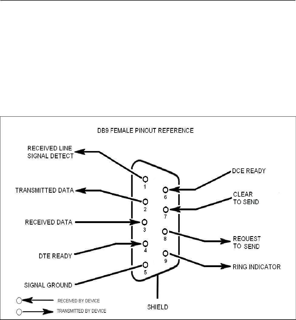
to local PC. The DB-9 pin
assignments
of COM 1 conform to the
standard
Electronic
Industries Association
(EIA232)
specifi
ca
t
i
on.
A
d
i
a
g
ra
m
of
the
p
i
n
d
e
scri
p
t
i
on
s
i
s
provided
b
e
l
o
w
for
re
f
e
re
n
ce
.
Conn
e
ct
i
ng
a
nu
ll
modem
ca
b
l
e
to the COM 1 port and using a
t
e
rmi
n
a
l
e
mu
l
a
t
i
on
program w
i
t
h
a PC
will
a
ll
o
w
commun
i
ca
t
i
on
to
t
h
e
control
processor
’
s
Text Menu
I
n
t
e
rf
a
ce
(TMI) for
t
ro
ub
l
e
sh
oo
t
i
ng
and
advanced
d
i
a
gno
st
i
cs.
C
a
ll
CSI
t
e
chn
i
ca
l
support
for
assistance
i
f
you
need
to
access these advanced features
or for further
information.
EIA232 Pin
Specifi
ca
ti
on
s
The
diagram above
is for
reference
only,
it’
s
intended
to provide a quick
source
for pinout information in the event it should be
neces-
sary to
adapt
your serial cable
because
of an
unusual connector
confi
gu
ra
t
i
on.
In
the vast
ma
j
o
ri
t
y
of
cases
t
h
i
s
i
n
f
orma
t
i
on
will
not
b
e
needed.
General Operation Overview
-16 -
Section 4
Software
Operations
Ethernet
The
Ethernet
AUI
conforms
to IEEE 802.3 and is
capable
of
supporting
10/100 Mbps
communications speeds.
This port is
used
to
pro-
vide
access
to the UI.
Monitoring
&
Alarms
There are no physical
connections
provided to exclusively and
specifi
ca
ll
y
commun
i
ca
t
e
system
or
a
l
a
rm
status.
I
n
f
orma
t
i
on
w
i
t
h
re
g
a
rd
to
system
or alarm
status
is provided by the TMI
accessible
via the
communication
ports
described
earlier.
Text Menu
I
nte
rfa
ce
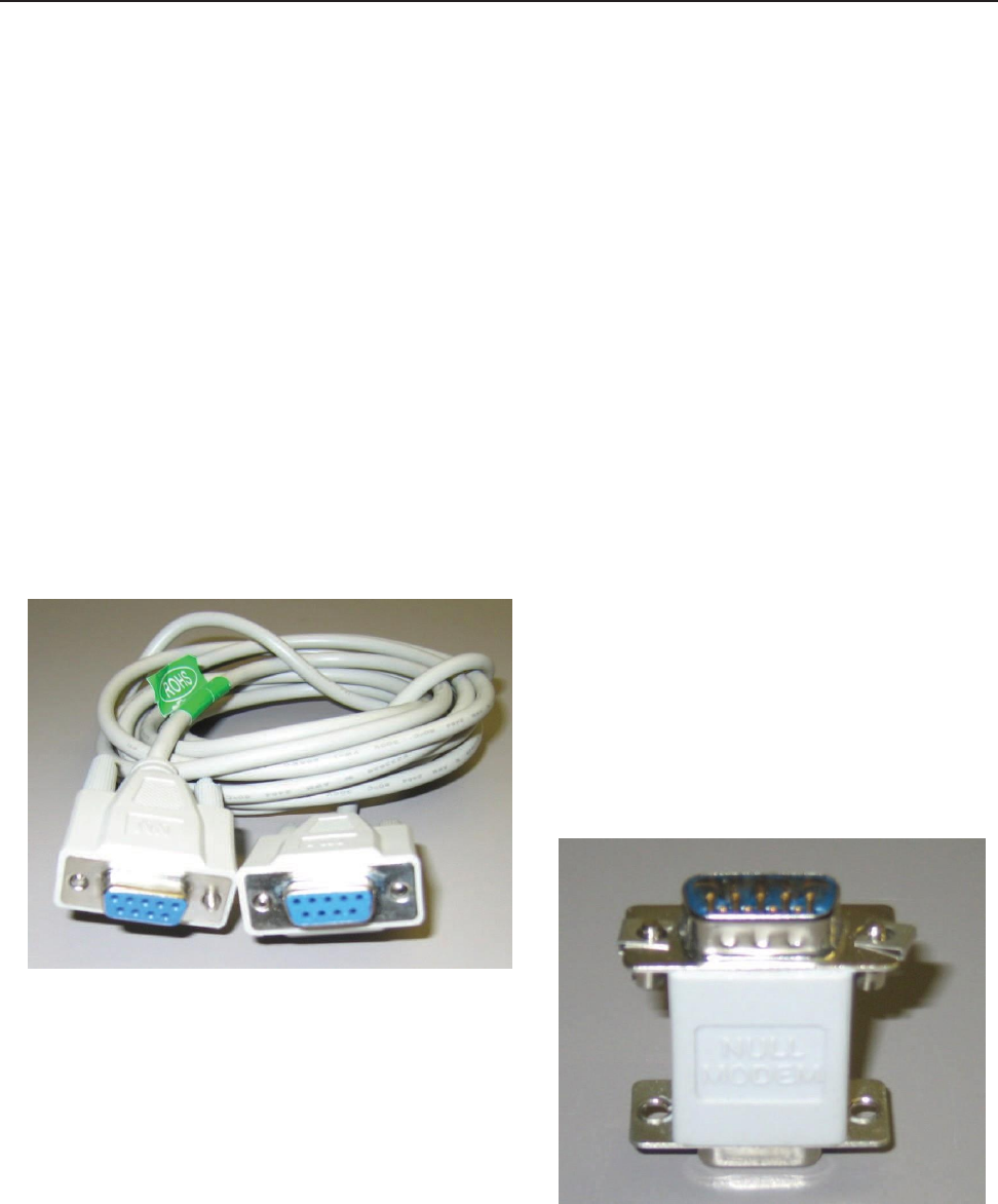
Local
Access
Local
access
to the
repeaters
TMI, also known
as
the
console interface,
is
made
by
connecting
a serial cable (optional),
as
shown in
figure 1,
f
rom
the
se
ri
a
l
connector
of
the
l
a
p
t
op
to the
se
ri
a
l
port
l
o
ca
t
e
d
on the top
of
the
enclosure
on the
ve
rt
i
ca
l
su
rf
a
ce
facing
the
rear and near the
heatsink.
This
connector
is not
labeled
and is
sealed
with a
special
cover to maintain the integrity of the
enclosure. This
cover must be
reinstalled
after the serial port is
used.
In
some cases,
if
the
connector gender
is not the
same as
shown in figure 1,
a
n
adapter
(optional)
as
shown in figure 2 may
a
l
so
be
re
qu
i
re
d.
Figure 1
Figure 2
General Operation Overview
- 17 -
Software
Operations
Section 4
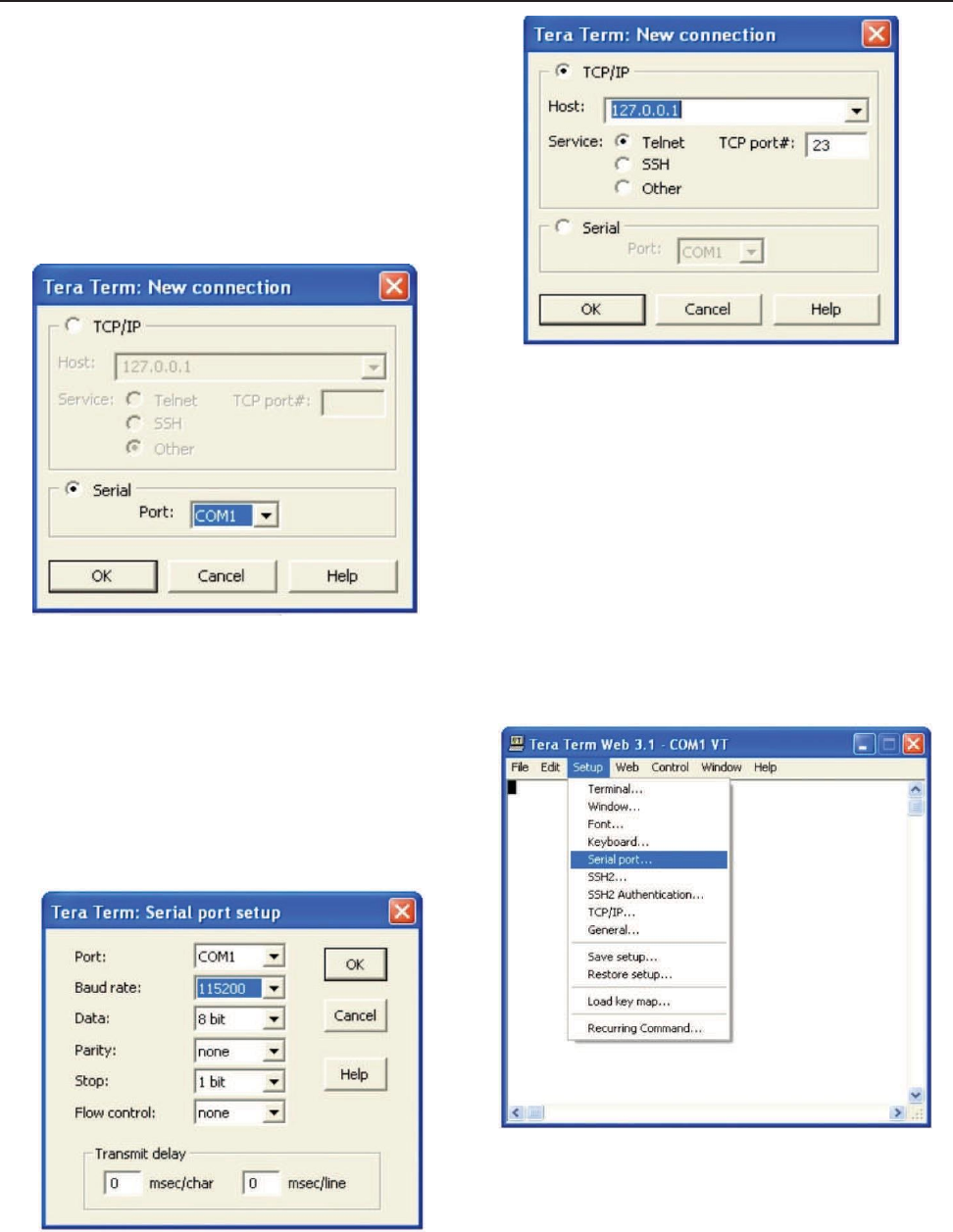
Many terminal
emulation programs
will
work
if
properly
configured.
In t
h
e
following
description,
“TeraTerm” is
used
to
establish
the TMI
session.
This
program
is readily
available
via the Internet and is free from
A
ye
ra
T
e
chno
l
og
i
e
s
at: http://www
.ayera.com/teraterm/
TeraTerm
Pro Web works on
W
i
ndo
w
s
95/98, 2000, XP. Here
i
s
the
l
a
t
e
st
TeraTerm
Pro Web
re
l
ea
se
:
Version 3.1.3,
October
8, 2002.
tt
p
ro
313.
zi
p
When the
program
is
started,
the
screen
to the right is
displayed.
Select
the Serial radio button and
press OK.
Note: It may be
necessary,
in the
System Properties section
of the control panel; using
Device
Manager
to
determine
what COM port your
computer uses
for the
communications
port. In this
case
it is COM
1.
Pressing
“OK” will
open up a blank dialog
screen.
Go to the
setup
dropdown
menu and
select
Serial port to make
changes
to the
serial
port
setup.
Configure
the
t
e
rmi
n
a
l
program
for
the correct COM port,
i
n
t
h
i
s
case
COM 1 and
115200
baud rate
as
shown
below
.
General Operation Overview
-18 -
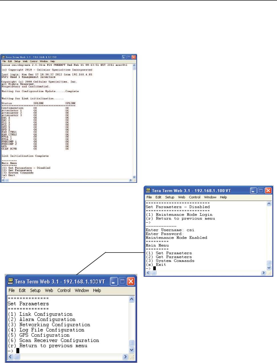
Software
Operations
Text Menu
I
nte
rfa
ce
Login
Section 4
Once the unit has
completed
its boot up and link initialization
phases
it
will
display the login prompt. The default
username
is
“bandone”
The default
password
is “csi1234”.
Main
Menu
When “Set
Parameters”
is first
se
l
e
ct
e
d
the
un
i
t
w
ill
ask for the
maintenance
mode login. (The
default
username
for the
maintenance
mode is “csi” and
the
password
is “csi1234”.)
Set
Parameters Menu
Once the
maintenance
mode login is
performed
successfully
the main menu
will
be
displayed again
but without the “(Disabled)” qualifier on the
“Se
t
Parameters” choice.
Selecting
(1)
will
display the Set
Parameters Menu.
General Operation Overview
-19 -
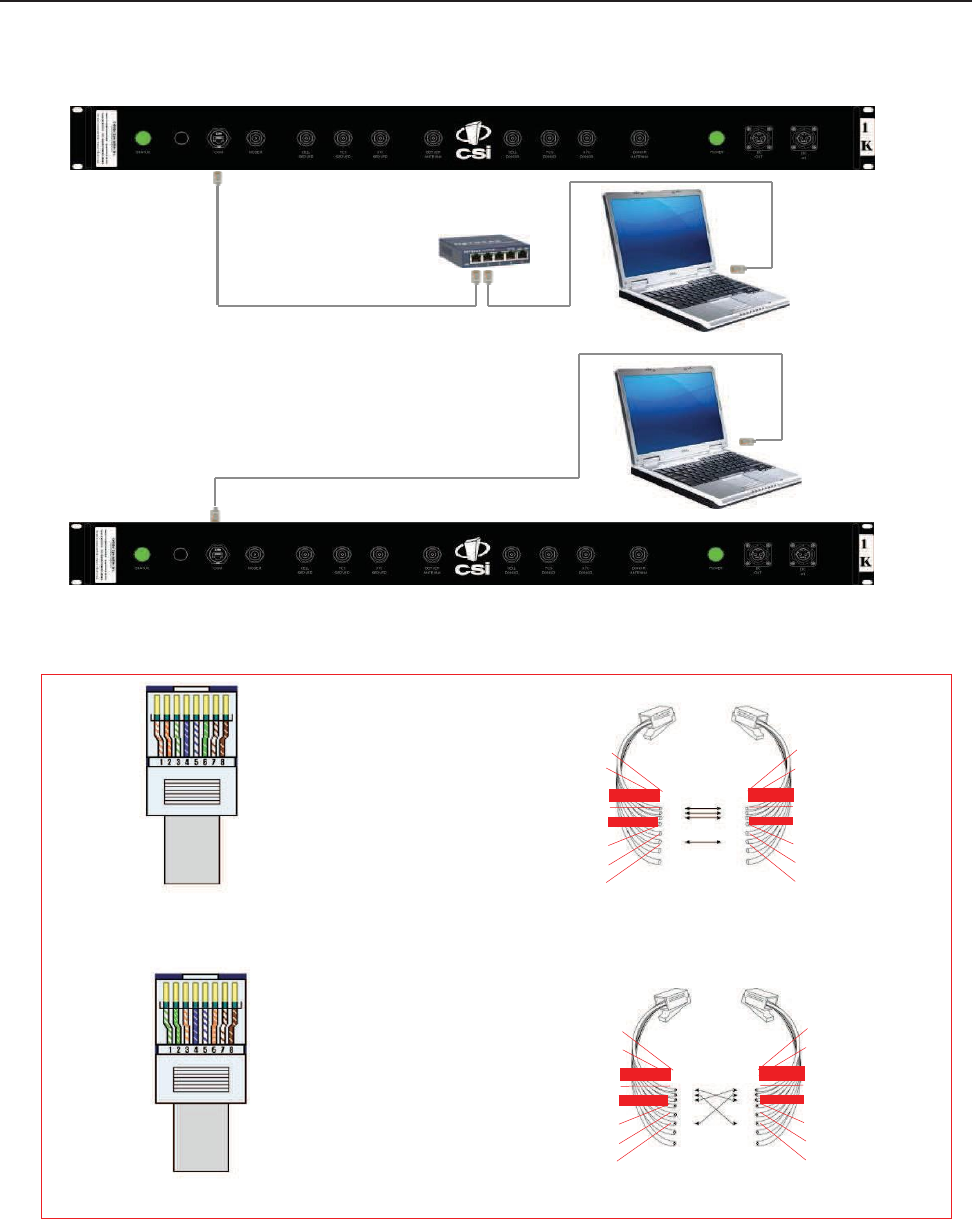
Software
Operations
Section 4
Telnet
Se
ss
i
on
T
C
P
/
I
P
The
diagram
below
shows
the normal use of
Crossed
and Straight
cables.
Repeater
Straight Cable
Network
Hub
or
Switch
PC
Straight Cable
Repeater
Crossed Cable
PC
Pin # Signal
AT&T
258
A
1 Transmit+
W
h
i
t
e
/
O
ra
ng
e
2 Transmit-
O
ra
ng
e
/W
h
i
t
e
or
O
ra
ng
e
3
R
e
ce
i
ve
+
W
h
i
t
e
/
G
re
e
n
4 N/A
Bl
u
e
/W
h
i
t
e
or
Bl
u
e
5 N/A
W
h
i
t
e
/
Bl
u
e
6
R
e
ce
i
ve
-
G
re
e
n
/W
h
i
t
e
or
G
re
e
n
7 N/A
W
h
i
t
e
/
Brow
n
8 N/A Brow
n
/W
h
i
t
e
or Brow
n
Pin # Signal
AT&T
258
A
1
R
e
ce
i
ve
+
W
h
i
t
e
/
O
ra
ng
e
2
R
e
ce
i
ve
-
O
ra
ng
e
/W
h
i
t
e
or
O
ra
ng
e
3 Transmit+
W
h
i
t
e
/
G
re
e
n
4 N/A
Bl
u
e
/W
h
i
t
e
or
Bl
u
e
5 N/A
W
h
i
t
e
/
Bl
u
e
6 Transmit-
G
re
e
n
/W
h
i
t
e
or
G
re
e
n
7 N/A
W
h
i
t
e
/
Brow
n
8 N/A Brow
n
/W
h
i
t
e
or Brow
n
Straight Cable
8
1
7
2
6
3
5
4
4
5
3
6
2
7
1
8
Crossed Cable
A
B
8
1
7
2
6
3
5
4
4
5
3
6
2
7
1
8
General Operation Overview
- 20 -
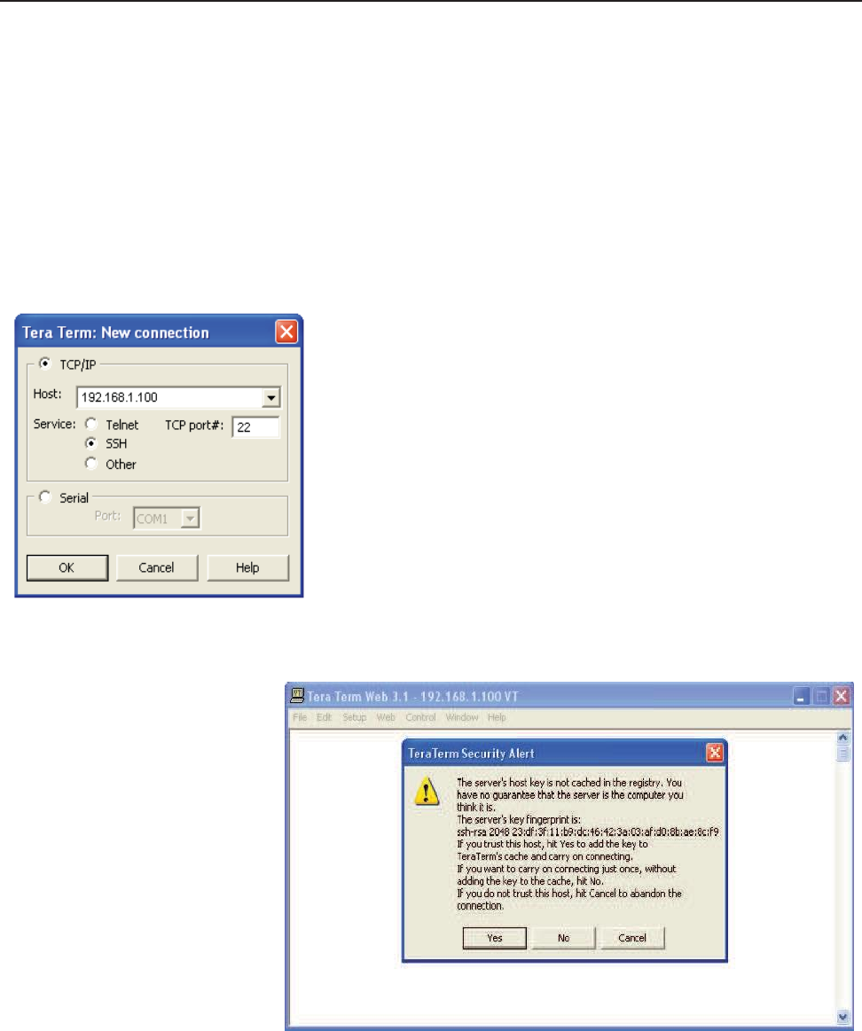
Software
Operations
Section 4
Remote access
to the
repeater
may be
gained
through a LAN
connection
and a terminal
emulation program
for TCP/IP.
As w
i
t
h
the
se
-
rial
connection,
many terminal
emulation programs
will
work,
if
properly
configured.
In
the
f
o
ll
o
w
i
ng
d
e
scri
p
t
i
on,
“TeraTerm”
i
s
used
t
o
establish
the TCP/IP
session.
Also, it
will
be
required
that the network
confi
gu
ra
t
i
on
of
the
computer
and the
repeater
b
e
i
ng
con
t
ro
ll
e
d
b
e
set up with the
same
Sub Net and Sub Net Mask in order to
establish
a link. In other words, the IP
addresses
of both the
computer
used
and the
repeater
must use the
same
group of IP
address number sets.
For
example,
the
repeater
ships with the default IP
address
of
192.168.1.100
and a Sub Net Mask
of
255.255.255.0.
In
order to
connect,
the
computer
to be
used
for
the
li
n
k w
ou
l
d
norma
ll
y
need
an
IP
address
of
something
like
192.168.1.12
with a Sub Net Mask of
255.255.255.0,
the
same
Sub Net Mask
as
the
repeater.
In this
example
note: the last digit of the IP
address
may be any
number except
1,100 and 255. Configuring your PC
i
s
norma
ll
y
f
a
i
rl
y
st
ra
i
gh
t
f
o
rw
a
rd
but it
does
vary
somewhat
with the
operating system
involved.
If
you require
assistance, contact
your IT
department
and they
will
be
able
to set up your PC for
you.
When the
TeraTerm program
i
s
started,
the
f
o
ll
o
w
i
ng
screen
i
s
d
i
sp
l
a
yed.
Change
the
d
e
f
a
u
l
t
host
I
P
address
to the
I
P
address
of t
h
e
repeater
to be
con
t
ro
ll
e
d.
In
the
case
of
a new
i
n
st
a
ll
,
the
d
e
f
a
u
l
t
address
i
s
192.168.1.100
and
has been assigned
at the
f
a
ctory
.
Select
the
service
SSH. The TCP Port must be
22
.
Click the yes button and the first
SSH
2
Authentication Challenge screen
is
dis-
played. The user then types the
username
in the
space provided.
To make
ch
a
ng
e
s
default user
name
is
“bandone” .
Pressing
the
“OK”
button may display the security alert shown
below
.
General Operation Overview
- 21 -
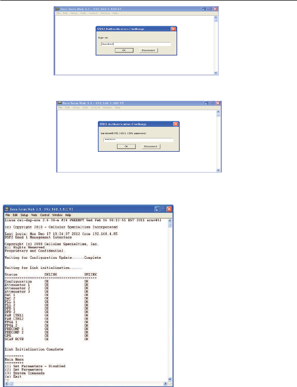
General Operation Overview
- 22 -
Software
Operations
Section 4
Press
OK after
entering
the user
name
and the
second
SSH2
Authentication Challenge
will
be
displayed.
In the
fi
e
l
d
provided, type the
user name
for
the
repeater
to be
changed.
The
d
e
f
a
u
l
t
password
i
s
“csi1234”
for all
repeaters.
After
typing
the
password press
OK and the main menu
will
be
displayed as
shown
next.
When “Set
Parameters”
is first
se
l
e
ct
e
d
the
un
i
t
w
ill
ask for the
maintenance
mode login. (The
default
username
for the
maintenance
mode is “csi”
and
the
password
is “csi1234”.)
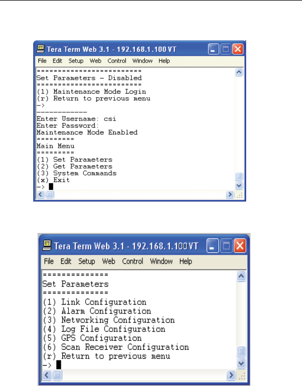
General Operation Overview
- 23 -
Software
Operations
Section 4
Set
Parameters Menu
Once the
ma
i
n
t
e
n
a
n
ce
mode
l
og
i
n
i
s
performed
successf
u
ll
y the
ma
i
n
menu
will
be
d
i
sp
l
a
yed
a
g
a
i
n
but w
i
t
hou
t
the
“(D
i
sa
b
l
e
d
)”
qu
alifi
e
r
on the “Set
Parameters” choice.
Selecting
(1)
will
display the Set
Parameters Menu.

General Operation Overview
- 24 -
Software Operations
Section 4
==============
Set
Parameters
==============
(1) Link
Confi
gu
ra
t
i
on
The
“Link
Confi
gu
ra
t
i
on
”
menu
i
s
a
co
ll
e
ct
i
on
of
menu
op
t
i
on
s
that
con
t
ro
l
the RF
op
e
ra
t
i
ng
ch
a
ra
ct
e
ri
st
i
cs
of
a
li
ve
system.
==================
Link
Confi
gu
ra
t
i
on
==================
(1) Adjust
Gain
The “Adjust Gain” option allows the user to control the total gain of the
system.
Valid gain
settings range
from
55
dB
to 90 db.
If
the user
selects
to
configure
the
do
w
n
li
n
k
g
a
i
n,
the
up
li
n
k
g
a
i
n
will
a
u
t
o
ma
t
i
ca
ll
y be
se
t
to the
sa
me
value. In order to override this condition, the user
will
have to
select
the uplink option and adjust the gain to
the
desired value.
-----------
Links:
(1) downlink
(2) uplink
(r) Return to
previous menu
Link?
-----------
User
Gain:
Setting
85.00 dB
User
Gain?
85.0
Auto Setting Uplink Gain to 85.00
dB
To override,
se
t
U
p
li
n
k
g
a
i
n
se
p
a
ra
t
e
l
y
(2)
Select
Active Filter
The “Select Active
fi
l
t
e
r”
op
t
i
on
a
ll
o
w
s
the
user
to
se
l
e
ct
the
fi
l
t
e
r
co
e
f
fi
ci
e
n
t
s
that have
been
l
o
a
d
e
d
i
n
the FPGA
f
o
r
test
purposes. Please
note that in order for this to work properly, the GPS task
needs
to be
disabled otherwise the
fi
l
t
e
r
se
l
e
ct
i
on
will
be
overridden
by the current
l
o
ca
t
i
on
of
the
syst
e
m.
----------------
FILTER
settings:
(1)
select
fi
l
t
e
r
co
e
f
fi
ci
e
n
t
(2) show
fi
l
t
e
r
co
e
f
fi
ci
e
n
t
(r) Return to
previous menu
FILTER
settings?
Filter Coefficient
T
a
b
l
e
fi
l
t
e
r
i
nd
e
x[
1
]
=
a
l
B0
F
0
-0
fi
l
t
e
r
i
nd
e
x[
2
]
=
a
l
B0
C
0
D
0
-0
fi
l
t
e
r
i
nd
e
x[
3
]
=
fi
l
t
e
r
i
nd
e
x[
4
]
=
fi
l
t
e
r
i
nd
e
x[
5
]
=
fi
l
t
e
r
i
nd
e
x[
6
]
=
fi
l
t
e
r
i
nd
e
x[
7
]
=
fi
l
t
e
r
i
nd
e
x[
8
]
=

Section 4
Software
Operations
fi
l
t
e
r
i
nd
e
x[
9
]
=
fi
l
t
e
r
i
nd
e
x[
10
]
=
fi
l
t
e
r
i
nd
e
x[
11
]
=
fi
l
t
e
r
i
nd
e
x[
12
]
=
fi
l
t
e
r
i
nd
e
x[
13
]
=
fi
l
t
e
r
i
nd
e
x[
14
]
=
fi
l
t
e
r
i
nd
e
x[
15
]
=
fi
l
t
e
r
i
nd
e
x[
16
]
=
----------------
FILTER
settings:
(1)
select
fi
l
t
e
r
co
e
f
fi
ci
e
n
t
(2) show
fi
l
t
e
r
co
e
f
fi
ci
e
n
t
(r) Return to
previous menu
FILTER
settings?
select
fi
l
t
e
r
[
1
-1
6
]
(3) Filter
Programming
The “Filter
Programming”
option allows the user to
select
and load one of the
loaded
fi
l
t
e
r
co
e
f
fi
ci
e
n
t
s
on the
sys-
tem. The user
will
be
prompted
to
select
which index the
fi
l
t
e
r
will
be
l
o
a
d
e
d
i
n
t
o,
one through
sixteen
or
a
ll
for t
e
st
purposes. Please
note that in order for this to work properly, the GPS task
needs
to be
disabled otherwise
the
fi
l
t
e
r
selection
will
be
overridden
by the current location of the
system.
-------------
Scan
USB for
fi
l
es?
(y
,n
):
File
names:
(1)
alA0B0-0
(2)
alA0B0C0D0E0F0-WD
(3)
alB0-0
(4)
alB0C0-0
(5)
alB0C0D0-0
(6)
alB0D0-0
(7)
alB0F0-0
(8)
alF0-0
(r) Return to
previous menu
Enter
fi
l
e
nu
mb
e
r?
Select
fi
l
t
e
r
ID
[
1
-1
6
]
[
99
=
a
ll
]
=>
-----------
==================
Link
Confi
gu
ra
t
i
on
==================
(1) Adjust
Gain
(2)
Select
Active Filter
(3) Filter
Programming
(4) PA Output
C
on
t
ro
l
(5) PA
O
sci
ll
a
t
i
on
Shutdown C
on
t
ro
l
(6) PA
O
sci
ll
a
t
i
on
T
i
me
r
C
on
t
ro
l
(r) Return to
previous menu
->
(4) Power Amplifier Output
C
on
t
ro
l
General Operation Overview
-25 -

Section 4
Software
Operations
The “Power Amplifier Output
C
on
t
ro
l
”
op
t
i
on
a
ll
o
w
s
the
user
to
con
t
ro
l
the
state
of
the power
a
mp
li
fi
e
r
,
ON or
OFF
.
The setting
overrides
all other PA
con
t
ro
l
tasks
and
i
s
persistent across reboots.
Care must be taken to
i
n
su
re
t
h
e
user is
aware
of the
state
of this setting so
as
to eliminate false
keyed/de-keyed
states.
-----------------
PA Output
En
a
b
l
e
:
(1) of
f
(2)
on
(r) Return to
previous menu
PA Output
En
a
b
l
e?
(r) Return to
previous menu
->
(2) Alarm
Confi
gu
ra
t
i
on
The “Alarm
Confi
gu
ra
t
i
on
”
menu
i
s
a
co
ll
e
ct
i
on
of
menu
op
t
i
on
s
that
con
t
ro
l
the
a
l
a
rmi
ng
op
e
ra
t
i
ng
ch
a
ra
ct
e
ri
st
i
cs
of a live
system.
===================
Alarm
Confi
gu
ra
t
i
on
===================
(1) Alarm
Masking
The “Alarm Masking” option provide the user an ability to mask or
unmask
individual
alarms based
on the
known
operating characteristics
of the
environment
that the unit is place in. Certain
alarms
will
occur that do not directly
af-
fect the proper
operation
of the
system
and can
therefore
be
masked.
All
alarms
are still
registered
with the
system
regardless
of the alarm
state,
user notifi
ca
t
i
on
on
l
y
takes
p
l
a
ce
d
on
unmasked
a
l
a
rms.
=============
Alarm
Masking
=============
(1) Show Alarm
Confi
gu
ra
t
i
on
Displays the current mask
state
of all the
alarms.
(2)Set Duplicate Alarm
interval
(3)
All
Alarms
Sets
all
alarms
to a given mask
state (ON/OFF).
(4) Link
Alarms
Sets
specific
a
l
a
rms
of
a
p
a
rt
i
cu
l
a
r
li
n
k to a
g
i
ven
mask
state (ON/OFF).
(5) HW/SW Alarm
Confi
gu
ra
t
i
on
Sets
specific
a
l
a
rms
of
a specific
sub-system
to a
g
i
ven
mask
state (ON/OFF).
(6)
Miscellaneous Alarms
Sets
specific
mi
sce
ll
a
n
e
ou
s
a
l
a
rms
to a
g
i
ven
mask
state (ON/OFF).
(r) Return to
previous menu
->
(2) Alarm
Notifi
ca
t
i
on
The “Alarm
Notifi
ca
t
i
on
”
op
t
i
on
provides
the
user
the
a
b
ili
t
y to
con
fi
gu
re
the
system
to
e
xt
e
rn
a
ll
y
no
t
i
f
y
service p
e
r-
sonnel
of alarm event
s.
==================
General Operation Overview
- 26 -

Section 4
Software
Operations
Alarm
Notifi
ca
t
i
on
==================
(1) Alarm Origin
T
a
g
The “Alarm Origin
T
a
g
”
op
t
i
on
provides user access
to two
se
tt
a
b
l
e
parameters
that are
used
to
d
i
st
i
ngu
i
sh
w
h
i
ch
system
is reporting the alarm. The user should
develop
a relative
scheme
of naming individual units so that
they
can
be easily identified by
service p
e
rso
nn
e
l
.
The two
parameters
are
i
n
cl
ud
e
d
as
part
of
the
a
l
a
rm
i
n
f
orma
t
i
on
t
h
a
t
is
sent.
================
Alarm Origin
T
a
g
================
(1) Host
Name
(2)
Location
(r) Return to
previous menu
(2) E-mail Alarm
Confi
gu
ra
t
i
on
==========================
E-mail Alarm
Confi
gu
ra
t
i
on
==========================
The “E-mail Alarm
Confi
gu
ra
t
i
on
”
op
t
i
on
con
fi
gu
re
s
the
e
-ma
il
a
l
a
rm
no
t
i
fi
ca
t
i
on
su
b-syst
e
m.
(1) Show E-mail
Confi
g
Displays the current
confi
gu
ra
t
i
on
of
the
e
-ma
il
su
b
syst
e
m.
(2)
Enable/Disable msmtp
Controls the
state
of the e-mail
sub-system,
the user must first
e
n
a
b
l
e
msmtp
i
n
order
for
any
e
-ma
il
a
l
a
rms
to
b
e
sent.
(3) Set
Recipient
Address
This option allows the user to
configure
up to five
d
e
st
i
n
a
t
i
on
e
-ma
il
addresses
that
will
re
ce
i
ve
system
a
l
a
rm
events.
It is best to
leverage
the
management
and
confi
gu
ra
t
i
on
op
t
i
on
s
of
a
d
e
st
i
n
a
t
i
on
ma
il
server
i
n
order
t
o
setup
a mail group of
service personnel
that
will
receive
the
alarms.
(4) Heart Beat Email
Confi
gu
ra
t
i
on
The
system
is
capable
of being
configured
to
send
out a
heartbeat
e
-ma
il
on a
p
e
ri
od
i
c
basis.
T
h
i
s
f
un
ct
i
on
can
b
e
used
to monitor the
operational state
of the
system.
(5)
Send
Test
Ema
il
Provided
that the e-mail
sub-system
is
enabled
and that there are
configured
d
e
st
i
n
a
t
i
on
addresses,
t
h
i
s
op
t
i
on
w
ill
generate
a test e-mail for
diagnostic
purposes.
(6) E-mail Client
Confi
gu
ra
t
i
on
This menu item provide
access
to user
confi
gu
ra
b
l
e
op
t
i
on
s
that
setup
the
e
-ma
il
cl
i
e
n
t
(DSP
system)
for
use w
i
t
h
an
authenticated
e-mail
server
and
account.
General Operation Overview
-27 -

Section 4
Software
Operations
(r) Return to
previous menu
->
(3) SMS
Message
Confi
gu
ra
t
i
on
The “SMS
Message
Confi
gu
ra
t
i
on
”
op
t
i
on
con
fi
gu
re
s
the SMS (Short
Me
ssa
g
i
ng
Service)
l
a
l
a
rm
no
t
i
fi
ca
t
i
on
su
b
-
system.
This option can be
used
to
send
alarm notifi
ca
t
i
on
s
to a
u
se
r
’
s
ce
ll
phone as
text
me
ssa
g
e
s.
(r) Return to
previous menu
->
(3)
Watchdog
T
i
me
r
C
on
fi
gu
ra
t
i
on
The “Watchdog
T
i
me
r
C
on
fi
gu
ra
t
i
on
”
op
t
i
on
con
fi
gu
re
s
a
hardware based watchdog
t
i
me
r
.
Once
e
n
a
b
l
e
,
the D
SP
software
will
periodically write to the
watchdog
timer thus
preventing
an
unscheduled
reboot. Certain
alarms
can
be
configured
to
i
nh
i
b
i
t
t
h
i
s
p
e
ri
od
i
c
write w
h
i
ch
i
n
turn
will
reboot the
system
when they
occu
r
.
============================
Watchdog
T
i
me
r
C
on
fi
gu
ra
t
i
on
============================
(1) ON
(2)
OFF
(3)
Reset Reboot Counter
(r) Return to
previous menu
->
(r) Return to
previous menu
->
(3) Networking
Confi
gu
ra
t
i
on
The “Networking
Confi
gu
ra
t
i
on
”
menu
con
t
a
i
n
s
three
con
fi
gu
ra
t
i
on
menus.
The
“L
o
ca
l
Network
C
on
fi
gu
ra
t
i
on
”
p
ro
-
vides
access
to the network
connection
that is
made
to the
system
via the
Ethernet
port
located
on the front
panel
of the unit. The “Remote Network
Confi
gu
ra
t
i
on
”
i
s
used
to
con
fi
gu
re
the w
i
re
l
ess
modem(s)
that are
attached
to
t
h
e
USB port of the SBC (single board
computer)
that controls the unit. The “SNMP
Confi
gu
ra
t
i
on
”
op
t
i
on
i
s
not
used
o
r
supported
in this version of
product.
========================
Networking
Confi
gu
ra
t
i
on
========================
(1) Local Network
Confi
gu
ra
t
i
on
The “Local Networking
Confi
gu
ra
t
i
on
”
menu
a
ll
o
w
s
the
user
to
con
fi
gu
re
the
Ethernet
port to
operate
i
n
one
of t
h
re
e
modes
once
enabled.
If
the unit is
configured
to have a
st
a
t
i
c
I
P
address,
then the
user
must know what the
ch
a
ra
c-
teristics of the network are that the unit
will
be
connected
to. In DHCP client mode, the unit
will
broadcast
a
request
for an IP
address
from a properly
configured
DHCP
server
on the network.
In
DHCP
server
mode
(d
e
f
a
u
l
t
) the
un
i
t
will
assign
itself an IP
address
of
192.168.1.100
and it
will
also listen for DHCP IP
address requests.
If
the
user
connects
a device (laptop) directly to the
Ethernet
port (cabling
requirements
may differ) the unit
will
issue
an IP
ad-
dress
of
192.168.1.90.
The unit is currently
capable
of issuing one client
address.
This is done to limit
cataclysmic
events
should the unit be
connected
to a network that
already
has a DHCP
server
.
----------------------
CAUTION: Network
reconfi
rma
t
i
on
may
cause
l
o
ca
l
and
remote access
i
n
t
e
rru
p
t
i
on
s.
General Operation Overview
-28 -

Section 4
Software
Operations
----------------------
===========================
Local Network
Confi
gu
ra
t
i
on
===========================
(1)
enable
(2)
disable
(3) set default static IP
(192.168.1.100)
(4) set labview calibration IP
(192.168.1.69)
(r) Return to
previous menu
->
(2)
Remote
Network
Confi
gu
ra
t
i
on
The “Remote Networking
Confi
gu
ra
t
i
on
”
menu
a
ll
o
w
s
the
user
to
con
fi
gu
re
the
modem connected
to the
i
n
t
e
rn
a
l
USB port of the SBC. This version of
software
is
preconfigured
to
e
n
a
b
l
e
the
d
e
f
a
u
l
t
modem
type
i
n
st
a
ll
e
d
i
n
t
h
e
unit and no user
selection
is
necessary
.
============================
Remote
Network
Confi
gu
ra
t
i
on
============================
(1)
enable modem
(2)
disable modem
(3) Set Modem
HeartBeat IpAddress
(r) Return to
previous menu
->
(3) SNMP
Confi
gu
ra
t
i
on
The “SNMP
Confi
gu
ra
t
i
on
”
menu
i
s
not
supported
for t
h
i
s
revision
of
the
p
ro
du
ct
.
==================
SNMP
Confi
gu
ra
t
i
on
==================
(1)
enable SNMP
============================
SNMP
Confi
gu
ra
t
i
on
Pa
rame
t
e
r
============================
(1) Show SNMP
Confi
g
(2) List NMS IP
A
dd
re
sses
(3) Clear NMS IP
A
dd
re
sses
(4)
Create
NMS IP
A
dd
re
ss
L
i
st
(5)
Heartbeat Control
(6)
Heartbeat Frequency
(7) Trap
C
on
t
ro
l
(8)
Restart
SNMP
Daemon
(9)
Send
Test
T
ra
p
/
I
n
f
o
rm
(r) Return to
previous menu
->
(2)
disable SNMP
(r) Return to
previous menu
(r) Return to
previous menu
(4) Log File
Confi
gu
ra
t
i
on
The
system
is
capable
of storing
it’
s
log
fi
l
es
p
e
rsi
st
e
n
t
l
y on a
p
e
ri
od
i
c
basis
so that post mortem
a
n
a
l
ysi
s
can
t
a
ke
General Operation Overview
- 29 -

Section 4
Software
Operations
place.
The log
fi
l
es
will
be
p
l
a
ce
d
i
n
the
“/
l
og
”
d
i
re
ct
o
ry on the
compact
flash. The
service p
e
rso
nn
e
l
can then
u
se
off
the
sh
e
l
f
a
pp
li
ca
t
i
on
s
to extract the
i
n
f
orma
t
i
on
to
t
h
e
i
r
l
a
p
t
op
for
re
vi
e
w
.
======================
Log File
Confi
gu
ra
t
i
on
======================
(1)
Display Log
Rotate Settings
Displays the current
settings
of the log
fi
l
e
ro
t
a
t
i
on
p
a
rame
t
e
rs.
(2)
Change
Log Rotation
Period
This option allows the user to control the
frequency
of the log rotation task which
will
persistently
store the log
fi
l
es
based
on
size.
(3)
Change
Minimum Log
Size
If
an running log
fi
l
e
exceeds
t
h
i
s
size (in bytes) the
l
og
fi
l
e
will
be
cop
i
e
d
to the
persistent storage
l
o
ca
t
i
on.
(4)
Change
Number of Logs
Rotated
This
parameter determines
the
number
of log
fi
l
es
of
each
type to
ma
i
n
t
a
i
n
i
n
persistent storage.
Once the
ma
xi
-
mum
number
is
reached,
older
fi
l
es
are
d
i
sca
rd
e
d
ke
e
p
i
ng
on
l
y the most
recent
fi
l
e
s.
(5)
Configure
Log to
F
il
e
This option allows the user to write the current
system status
information to the
appropriate
log
fi
l
e
on a
p
e
ri
od
i
c
basis.
(r) Return to
previous menu
->
(5) GPS
Confi
gu
ra
t
i
on
The GPS
sub-system
is an integral part of the control of the DSP
based system.
During normal
operating
mode,
the
GPS
receiver
controls the
selection
of
fi
l
t
e
rs
and the key
state
of
the
un
i
t
.
The
un
i
t
must first
re
ce
i
ve
a
va
li
d
G
PS
string from the
satellites
before the unit
will
perform properly. The
f
o
ll
o
w
i
ng
menu
a
ll
o
w
s
the
user
to
examine
a
nd
configure
the GPS
op
e
ra
t
i
ng
parameters
of
the
un
i
t
.
=================
GPS
Confi
gu
ra
t
i
on
=================
(1) Set GPS
Mode
The GPS mode menu controls the
operational state
of the GPS
receiver.
The
system
i
s
designed
to run w
i
t
h
a
G
PS
emulator connected
to COM3 (internal) for use
s
a
test/debug
mode. Additional menu items can be
used
to
assist
in
the
diagnosis
of GPS
related
issues.
============
Set GPS
Mode
============
(1)
Enable
GPS
Receiver
(default
enabled)
(2)
Enable
GPS Emulator (default
disabled)
(3) Disable GPS
Receiver
(default
enabled)
(4) Set GPS
Source
Device (default Network Host
Client)
(5) Set GPS ECP IP
A
dd
re
ss
(d
e
f
a
u
l
t
192.168.1.101, 192.168.100
)
(6)
Enable/Disable
Amplifier
(d
e
f
a
u
l
t
e
n
a
b
l
e
d
)
(7) Set No Box
Shutdown
Mode (default
enabled)
(8) Set No
Satellites Shutdown
Mode (default
enabled)
(r) Return to
previous menu
->
New to the GPS mode menu controls is the ability to
select
the
source
of the GPS
signal/mode used
by
system.
General Operation Overview
- 30 -

Section 4
Software
Operations
The
system
is now
capable
of receiving a GPS signal via an
Ethernet connection
to a host
system
which itself
is
connected
to a GPS
source.
This mode of
operation
is the default for the Acela AWS
un
i
t
and
it
i
s
con
fi
gu
re
d
t
o
primarily
access
the Acela CELL unit and
secondarily
the Acela PCS
unit.
============
Set GPS
Mode
============
(1)
Enable
GPS
Receiver
(2)
Enable
GPS
Emulator
(3) Disable GPS
Receiver
(4) Set GPS
Source Device
(5) Set GPS ECP IP
A
dd
re
ss
(6)
Enable/Disable
Amplifier
(7) Set No Box
Shutdown Mode
(8) Set No
Satellites Shutdown Mode
(r) Return to
previous menu
->
(1) TTY
Device
(2) Network Host
Client
(3) Network Host
Server
Enter GPS
Source
and *reboot*
system ->
Also new to the GPS mode menu controls is the ability to
select
the IP
address
of the
source
of the GPS
signal/
mode
used
by
system.
This is typically
used
in a
laboratory environment
when
systems
are not installed in
the
actual
trains.
============
Set GPS
Mode
============
(1)
Enable
GPS
Receiver
(2)
Enable
GPS
Emulator
(3) Disable GPS
Receiver
(4) Set GPS
Source Device
(5) Set GPS ECP IP
A
dd
re
ss
(6)
Enable/Disable
Amplifier
(7) Set No Box
Shutdown Mode
(8) Set No
Satellites Shutdown Mode
(r) Return to
previous menu
->
-------------------------------------
ECP
Management Server
IP
A
dd
re
ss:
*
Enter up to 5 IP
A
dd
re
sses
*
Hit 's' to
save
new list
*
Hit 'r' to return to
menu
Setting
(192.168.1.101)
ECP
Management Server
IP
A
dd
re
ss
1?
nnn.nnn.nnn.nnn
GPS ECP
addresses:
(2) Set
T
i
me
I
n
t
e
rva
l
=================
Set
T
i
me
I
n
t
e
rva
l
=================
General Operation Overview
- 31 -

Software Operations
Section 4
(1) Set Test D
e
l
a
y
A
user
se
l
e
ct
e
d
period
used
to
d
e
l
a
y
(i
nh
i
b
i
t
) the
ru
nn
i
ng
of
the GPS
t
a
sk.
(2) Set GPS
Receive Update Interval
This
parameter determines
interval at which the GPS task
acquires
the GPS
Receiver data.
It can be in
seconds
and
microseconds.
The default is 1
sec.
(3) Set
Program
Filter
Interval
The interval the GPS task
programs
the Filter.
T
h
i
s
i
s
one
of
the
parameters
for
programming
the
fi
l
t
e
r
.
The
d
e
f
a
u
l
t
value is 18
sec.
Other
parameters
for
fi
l
t
e
r
programming
are
d
i
st
a
n
ce
t
ra
ve
ll
e
d
a
f
t
e
r one
fi
l
t
e
r
i
s
programmed. Ex-
cept during the initial
programming
period when both
fi
l
t
e
r are
p
ro
g
ra
mmed.
(4) Set No Data
T
i
me
ou
t
I
n
t
e
rva
l
The interval the GPS task can be without receiving any data from GPS
Receiver.
A
f
t
e
r w
h
i
ch
an
a
l
a
rm
i
s
sent
a
nd
the PA
i
s
turned OFF. The
d
e
f
a
u
l
t
va
l
u
e
i
s
25
se
c.
(5) Set Polling
Interval
The interval for which the GPS task
remains disabled
after the PA
i
s
turned OFF. The
d
e
f
a
u
l
t
i
s
50
se
c.
(6) Set Emulator
Update Interval
The interval the GPS task
reads
the GPS Emulator data from the test port. The default is 15
sec.
(r) Return to
previous menu
->
(3) Set
Programming Distance
========================
Set
Programming Distance
========================
(1) Set
Distance
To
Program
F
il
t
e
r
The
distance
the train may travel after
programming
one
fi
l
t
e
r at w
h
i
ch
the next
fi
l
t
e
r
i
s
programmed.
The D
e
f
a
u
l
t
i
s
quarter
mile (0.25
miles).
(2) Set Maximum
Distance
To
Program
F
il
t
e
r
The maximum
distance
the train can travel before
programming
the next
fi
l
t
e
r
.
D
e
f
a
u
l
t
i
s
5
mi
l
e
s.
(r) Return to
previous menu
->
(4) Set Maximum
Count
=================
Set Maximum
Count
=================
(1) Set Maximum No Box
Count
The maximum count for No Box (no fix data)
b
e
f
o
re
an
a
l
a
rm
i
s
sent
and the PA
i
s
turned OFF. D
e
f
a
u
l
t
i
s
1500
~
25mins
(2) Set Maximum No Satellite
Count
The maximum count for not
enough satellites
(minimum is 3) before an alarm is sent and the PA
i
s
turned
OFF
.
Default is 1800 ~
30mins
(r) Return to
previous menu
->
(4) Set Test
L
o
ca
t
i
on
Used to
select
the location of the test
fi
l
t
e
r
se
t
used
for t
ro
ub
l
e
sh
oo
t
i
ng
pu
rp
o
se
s.
=================
Set Test
L
o
ca
t
i
on
=================
(1) Set Default Test
L
o
ca
t
i
on
(2) Set Box For Test
L
o
ca
t
i
on
(r) Return to
previous menu
General Operation Overview
- 32 -

Software Operations
Section 4
->
(6)
Read
GPS
Parameters
Displays the current GPS
confi
gu
ra
t
i
on
se
tt
i
ng
s.
======================================================
GPS
Parameters
======================================================
Run
State
En
a
b
l
e
d
Debug Msg Level
0
PA
C
on
t
ro
l
Mode
En
a
b
l
e
d
LookUp
T
a
b
l
e
Size
10
Test D
e
l
a
y
0
GpsRx
Update
Interval 1
secs:0 usecs
Program
Filter Interval 18
secs
NoData
T
i
me
ou
t
I
n
t
e
rva
l
25
secs
Polling Interval 50
secs
Emulator
Update
Interval 15
secs
Max NoBox Count
1500
Max No
Satellites
Count
1800
NoBox
Shutdown
Mode
Enabled
No
Satellites Shutdown
Mo
Enabled
======================================================
(7) Set Debug
Message Level
User
se
l
e
ct
a
b
l
e
debug
l
e
ve
l
,
messages
are
sent
to the
“/
va
r/
l
og
/
d
r6
10_2.
l
og
”
fi
l
e
.
(0) Display No
Msg
(1) Display Info
Msg
(2) Display Debug
Msg
(3) Display More Debug
Msg
Enter GPS Debug Msg Level (0)->
(r) Return to
previous menu
->
(6)
Scan Receiver
Confi
gu
ra
t
i
on
The
scan receiver hardware
is
used
to monitor the power levels of a set of
frequencies
for a given
fi
l
t
e
r
set.
If
t
h
e
scanned
power level is
above
the maximum
threshold
value, the task
will
de-key the unit until such a condition
no
longer
exists.
===========================
Scan Receiver
Confi
gu
ra
t
i
on
===========================
(1)
Scan Receiver Operation
This option is
used
to control the
state
of the
scan receiver
task
(ON/OFF).
(2)
Read Scan Receiver
Parameters
Displays the current
confi
gu
ra
t
i
on
se
tt
i
ng
s
of
the
scan
re
ce
i
ve
r
t
a
sk.
(3)
Channel Sample Count
The
number
of
samples
per
channel
to
acquire
in order to
compute
an
average
power
value.
(4) Key/De-key
Threshold
The maximum power level in dBm which
will
cause
the
scan receiver
task to de-key the
P
A
.
(5) PA
Recovery
T
i
me
The period of time in
seconds
that the unit
will
remain in a
de-keyed state
following an oscillation
induced de-key.
(6) De-key
Sample Count
General Operation Overview
- 33 -

Software Operations
Section 4
The
number
of power
readings
to
sample
in order to
compute
the rolling
average
of the current
scanned channels.
(7)
Short/Fast
Key
Sample Count
The
number
of power
readings
to
sample
in order to
compute
the
short/fast average
of the current
scanned chan-
nels.
(See
product
specifi
ca
t
i
on
docu
me
n
t
)
(8) Long/Slow Key
Sample Count
The
number
of power
readings
to
sample
in order to
compute
the long/slow
average
of the current
scanned chan-
nels.
(See
product
specifi
ca
t
i
on
docu
me
n
t
)
(9)
Fast/Slow
Key Delta
V
alue
The value in dBm that
determines
if
a fast or slow key
decision
is
made.
(r) Return to
previous menu
(r) Return to
previous menu
->
==============
Get
Parameters
==============
The “Get
Parameters”
menu is
available
to all
users
in order to view
system status
information and
diagnose alarm
information.
(1) Link
Status
The
“Link
Status” option
displays
the current
state
of the
system parameters.
Information on this
page
is
used to
diagnose
the health of the
system.
=============================================================================
T
i
me
st
a
mp
:
2012:12:21
-
15:20:16
UTC U
T
C
=============================================================================
Uptime : 2 days 20 hours 46
minutes
=============================================================================
Power (dBm) DNLINK UPLINK
=============================================================================
IN-BAND INPUT
-83.42
-65.58
COMPOSITE INPUT
-50.70
-56.66
MEASURED
OUTPUT
3.58
21.42
CALIBRATED
OUTPUT
27.40
33.00
MAXIMUM
OUTPUT
27.40
33.00
VSWR
----
++++
=============================================================================
AGC Control (dB)
=============================================================================
MODE ON
---/--- 0.00
0.00
=============================================================================
Status
=============================================================================
VOLTAGE OK OK
TEMPERATURE OK
OK
SOFTWARE
OK
OK
HARDWARE OK OK
OSCILLATION
OK
OK
OVERRANGE OK
OK
CALIBRATION OK
OK
=============================================================================
General Operation Overview
- 34 -

Software
Operations
Section 4
DC
Current
=============================================================================
AMPERAGE
3.54
=============================================================================
Temperature
(C
e
l
si
u
s)
=============================================================================
CPU 40.06 new item,
displays
the
temperature
of the Single Board
Computer
FPGA
53.75
=============================================================================
Power Amplifier
=============================================================================
STATUS
O
N
AMPERAGE 0.89
6.31
TEMPERATURE ----
66.84
=============================================================================
Fan
Confi
gu
ra
t
i
on
=============================================================================
STATE OFF
OFF
STATUS OK OK
=============================================================================
System
Confi
gu
ra
t
i
on
=============================================================================
GAIN (dB) 87.00
87.00
FILTER
alB0F0-0
=============================================================================
(2)
System Events
The “System Events” option
displays
the current list of
system alarms.
Alarm
statistics
are
maintained
in the
“Show
Counts”
option.
============
System Events
=============
(1) List
(2) Show
Counts
(3)
Clear
(r) Return to
previous menu
(3)
System Information
The “System Information” option
displays
the current
state
of the non-RF
parameters.
======================================================
System
Info:
2008:11:18
-
20:54:46 UTC
======================================================
Location
Software_lab
System
Type
C
SI
-D
SP8
5
-
A
Board Type
PCS - Rev. B
Carrier Verizon EVDO
SW Version
02.03.00 RC5
Serial Number
CDJ80150-000148
Item Number
CS10-369-xxx
Date Built
10/08/2008
Watchdog
T
i
me
r
En
a
b
l
e
d
General Operation Overview
- 35 -

Software Operations
Section 4
======================================================
Local Area
Network:
======================================================
Hostname
csi-acela-beta5
Boot Protocol
dhcp
I
P
A
dd
re
ss
192.168.1.90
MAC
Address
======================================================
Wide Area
Network:
======================================================
PPP Enabled
YES
Modem Type CDMA
PPP0 Address
166.143.7.196
PPP0
MAC
Address 166.143.7.196
PPP1 Address
0.0.0.0
PPP1
MAC
Address
======================================================
SNMP
Confi
gu
ra
t
i
on
:
======================================================
Enabled
YES
T
ra
p
s/
I
n
f
orms
N
O
Heartbeat
NO
======================================================
MODEM
Status Information
======================================================
MODEM
#1
RSSI (dBm) -69 (OK)
Registration
Sts Modem has
registered
Phone
Number
9084425314
Current Band Cellular
Sleep
System
ID
28
Network ID
5
Temperature
(C)
36
======================================================
GPS Location
Data
======================================================
Run
State
Enabled
Latitude
42.997005
Longitude
-71.468246
Filter ID
1
Filter Name
pcR0A0D0B0E0F0C0-Wid
Location
Manchester
BTA
500
Satellite Count
3
NoBox Count
0
Searching
Count
0
======================================================
Scan Receiver
MHz avg
dBm
======================================================
Run
State
Enabled
Dekey Limit
-65.00
Filter ID
1
Channels
11
General Operation Overview
- 36 -

Software Operations
Section 4
Channel-1
1971.25
-1
10.58
Channel-2
1972.50
-1
10.38
Channel-3
1973.75
-1
10.72
Channel-4
1975.00
-1
10.82
Channel-5
1976.25
-1
10.00
Channel-6
1977.50
-1
11.49
Channel-7
1978.75
-1
11.35
Channel-8
1980.00
-1
11.06
Channel-9
1981.25
-1
10.67
Channel-10
1982.50
-1
10.96
Channel-11
1983.75
-1
11.01
======================================================
(4) Link
Status Loop
The
“Link
Status
Loop” option
displays
the current
state
of the
system
on a periodic
basis
in the form of a
parse
able
string. Mode
‘0’
displays
a list of
system parameters
on a periodic
basis.
Mode
‘1’
displays
a list of
system pa-
rameters
every time the
fi
l
t
e
r
se
l
e
ct
i
on
changes.
Mode
‘
2
’
d
i
sp
l
a
ys
a
li
st
of
scan
re
ce
i
ve
r
parameters
on a
p
e
ri
od
i
c
basis.
Mode
‘3’
displays
a list of power
detector values
on a periodic
basis.
Enter loop delay ->
2
Display Mode (0 = normal, 1 = BTA
changes,
2 =
ScanRcvr
RSSI, 3 = power) ->
0
2012:12:21, 16:50:26
UTC, 2:22:16, 48.00, 48.00, 43.18, 0.00, 0.49,
Providence, 42.038258, -71.216042,
8, 2,
1,
2, alA0B0-0, alB0F0-0, 1, 0x10, 1,
-120.86,
-92.38, -50.94, -56.66, -33.86, -5.38, 87.00, 87.00, 0.0, 0.0, OK, OK,
OK, OK, OK, OK, OK, OK, OK, OK, OK, OK, NM, 2, -65.00, 1, 8, 4, 12, -13.61, -13.62, -13.59, 12, 1,
2120.62,
-13.82, 2,
2121.88,
-13.67, 3,
2123.12,
-13.87, 4,
2124.38,
-14.23, 5,
2125.62,
-14.50, 6,
2126.88,
-14.64,
7,
2128.12,
-14.52, 8,
2129.38,
-14.56, 9,
2130.62,
-14.62, 10,
2131.88,
-14.60, 11,
2133.12,
-14.64, 12,
2134.38,
-14.64,
General Operation Overview
- 37 -

Software Operations
Section 4
The
repeater
’
s
op
e
ra
t
i
ng
so
f
t
w
a
re
have two
modes,
an
O
p
e
ra
t
i
on
a
l
mode and a
Ma
i
n
t
e
n
a
n
ce
mode.
These
are
de-
scribed
below
.
Operational Mode:
Upon power up, the
System
will
begin
operation
in the
Operational
Mode. Using a “Band
Sw
i
t
ch
i
ng
A
l
go
ri
t
h
m”
the
re
p
ea
t
e
r
will
not key until a GPS position fix
i
s
ob
t
a
i
n
e
d
and the
un
i
t
i
s
w
i
t
h
i
n
an Area D
e
fi
n
i
t
i
on.
Once GPS position fix
i
s
ob
t
a
i
n
the
repeater
will
b
e
g
i
n
op
e
ra
t
i
on
based
on the Area D
e
fi
n
i
t
i
on
s
“C
h
a
nn
e
l
Power
Me
a
su
re
-
ment and Keying Decision” and “Low Isolation
Detection
and Protection”
algorithms.
The
operational software
will
continu-
ously monitor the
system’s environment
and make the
necessary adjustments
to keep the product
operating
with
specifi
ca
-
tions and within the normal
operating range
of the
Product
and FCC Type
C
e
rt
i
fi
ca
t
i
on.
System Status
The
Operating Software provides
real time
status
data that
reports
the
state
of the
repeater.
This
status contains:
T
i
me
st
a
mp
Modem Band
T
yp
e
Sa
t
e
lli
t
e
Coun
t
System
Up
T
i
me
A
ct
i
ve
F
il
e
r
NoBox
Coun
t
So
f
t
w
a
re
V
e
rsi
on
I
n
-b
a
nd
i
npu
t
Se
a
rch
i
ng
Coun
t
System
Se
ri
a
l
N
umb
e
r
Measured
O
u
t
pu
t
Scan
RX Run
St
a
t
e
Mo
d
e
l
N
umb
e
r
Composite
I
npu
t
DeKey
L
i
mit
I
t
e
m
N
umb
e
r
AGC Mo
d
e
Scan
RX
F
il
t
e
r
I
D
L
o
ca
t
i
on
AGC
A
tt
e
nu
a
t
i
on
#
of
Ch
a
nn
e
l
s
Modem
Si
gn
a
l
Stre
ng
t
h
GPS
Run
St
a
t
e
1 -10
Ch
a
nn
e
l
F
re
q
’
s
&
SSI
Modem
R
e
g
i
st
ra
t
i
on
St
a
t
u
s
L
a
t
i
t
ud
e
Modem
Phone N
umb
e
r
L
ong
i
t
ud
e
RF
Alarms:
System Alarms:
Modem Current
Band
F
il
t
e
r
I
D
Over
R
a
ng
e
Synthesizer
L
o
ck
Modem
System
I
D
F
il
t
e
r N
a
me
O
sci
ll
a
t
i
on
V
o
l
t
a
g
e
Modem Network
I
D
L
o
ca
t
i
on
VSW
R
T
e
mp
e
ra
t
u
re
Modem
T
e
mp
e
ra
t
u
re
BTA
Out
of
Band
O
ve
rd
ri
ve
So
f
t
w
a
re
Low
Si
gn
a
l
H
a
rd
w
a
re
No
Si
gn
a
l
Currently
System events
are
stored
to a Log File. In future
releases,
with the
exception
of the
System
Serial Number
and
System
Identifier, The
R
ea
l
T
i
me
Status
of
the
Product
will
be
saved
to
non
vo
l
a
t
il
e
memory
for
re
t
ri
e
va
l
.
The
non
vo
l
a
t
il
e
memory
will
be able to store 48 hours of
Status data,
with up to 6
complete status records
per minute. The interval that
the
status records
are
saved
will
be user
defi
n
e
d.
The
Operating Software
will
also record to nonvolatile memory and make
available
to a user in the
Maintenance Mode:
- A count and
t
i
me
stamp each
t
i
me
the
processor
i
s
boo
t
e
d.
- A count and
t
i
me
stamp
of
each
t
i
me
the
op
e
ra
t
i
ng
so
f
t
w
a
re
i
s
p
l
a
ce
d
i
n
t
o
the
Ma
i
n
t
e
n
a
n
ce
Mode, and the
User
ID
o
f
the
operator
that
performed
the
action.
- A count and
t
i
me
stamp each
t
i
me
the
Watchdog
T
i
me
r
i
s
a
ct
i
va
t
e
d,
and the
associated
d
e
bugg
i
ng
i
n
f
orma
t
i
on
a
va
il
-
able at the time of activation of the
Watchdog
T
i
me
r
.
- The count and
t
i
me
stamp
of
any
a
ct
i
va
t
i
on
of
the “Low
I
so
l
a
t
i
on
D
e
t
e
ct
i
on
and
Pro
t
e
ct
i
on
A
l
go
ri
t
h
m”
as
d
e
fi
n
e
d
i
n
a
t
-
tachment
C of this
document.
A
l
a
r
m
s
The
Operating Software
has the ability to monitor a
System
for
conditions
that are out of normal
operation,
triggering
an
alarm event. The
Operating software
in
conjunction
with the
Communications Subsystem
is
capable
of
sending
alarm
mes-
sages
via E-mail using
standard
SMTP and
POP3 protocols
to a User
Provisioned
e-mail
account
.
Each Alarm
defined has these User Provisioned C
a
p
a
b
ili
t
i
e
s.
:
-
Disable
the
System:
The
Operating software
can
disable
the
System
(prohibit Keying) until the alarm
condition
is
cleared.
- Alarm Filter
Conditions:
A
F
il
t
e
r
Cond
i
t
i
on
(such
as
X
number
of
occurrences
per hour) to the
a
l
a
rm
to
p
re
ven
t
false or
un-useful notifi
ca
t
i
on
s
if
p
ro
vi
sion
e
d.
-
Send
an Alarm
Message:
The
O
p
e
ra
t
i
ng
So
f
t
w
a
re
can
send
a
no
t
i
fi
ca
t
i
on
via
message
E-ma
il
through the
Co
m-
munications Subsystem
if
provisioned.
- Alarm
Clear Message:
The
O
p
e
ra
t
i
ng
So
f
t
w
a
re
can
send
an
a
l
a
rm
clear
message
when an
a
l
a
rm
cond
i
t
i
on
clears
if
provisioned.
General Operation Overview
- 38 -
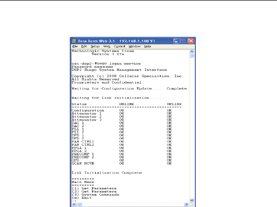
Software
Operations
Section 4
Maintenance Mode
The
repeater has,
in addition to
it’
s
norma
l
“O
p
e
ra
t
i
on
a
l
Mo
d
e
”
a
“Ma
i
n
t
e
n
a
n
ce
Mode”.
A
f
t
e
r
system
boot up
t
h
i
s
mode can be
accessed
i
n
the TMI only by typing the user
name
and
password
of
service.
T
h
i
s
mode
of
op
e
r
a
t
i
on
p
r
o
v
i
d
e
s
a
ll
the
same menus
and
f
ea
t
u
r
e
s
as shown
i
n
the
s
o
f
t
w
a
r
e
o
v
e
rv
i
e
w on
p
r
e
v
i
ou
s
p
a
g
e
s
except
that upon
entering
the
Maintenance
Mode, the product will de-key and await
instructions
from a
conn
e
ct
e
d
user. During the
Maintenance
Mode of
operation
the
Operating Software supports:
-
Ma
nu
a
l
op
e
ra
t
i
on
of
the Key/De-Key
f
un
ct
i
on.
-
Ma
nu
a
l
op
e
ra
t
i
on
of
the Area D
e
fi
n
i
t
i
on
Sw
i
t
ch
i
ng
f
un
ct
i
on.
-
Ma
nu
a
l
Se
tt
i
ng
of
the
g
a
i
n
se
tt
i
ng
i
n
both the U
p
li
n
k and D
o
w
n
li
n
k D
i
re
ct
i
on
s
-
R
e
t
ri
e
va
l
of
a
ll
current
User Provisioned
Se
tt
i
ng
s
f
rom
the
Pro
du
ct
-
R
e
t
ri
e
va
l
of
the Current Version
of
so
f
t
w
a
re
i
n
the
Pro
du
ct
-
Se
tt
i
ng
of
a
ll
User Provisioned
Se
tt
i
ng
s
-
R
e
t
ri
e
va
l
of
l
ogg
e
d
Status
d
a
t
a
-
R
e
t
ri
e
va
l
of
boot
counts,
Ma
i
n
t
e
n
a
n
ce
Mode entry
counts,
Watch Dog
t
i
me
r
events w
i
t
h
d
e
bugg
i
ng
data,
a
nd
Low Isolation
Detection
and
Protection
events.
- The
Ability
to D
i
sa
b
l
e
and
En
a
b
l
e
the
Syst
e
m.
- A Method to
a
u
t
o
ma
t
i
ca
ll
y
p
l
a
ce
the
System
back
i
n
t
o
op
e
ra
t
i
on
upon the
d
i
sco
n
t
i
nu
a
n
ce
of
the
Ma
i
n
t
e
n
a
n
ce
session.
- A Method to
a
u
t
o
ma
t
i
ca
ll
y
p
l
a
ce
the stem back
i
n
t
o
op
e
ra
t
i
on
a
f
t
e
r a
User Provisioned
t
i
me
limit of
i
n
a
ct
i
vi
t
y
i
n
the
Maintenance Mode.
-
Ability
to
l
o
a
d
O
p
e
ra
t
i
ng
So
f
t
w
a
re
i
n
t
o
the
re
p
ea
t
e
r
’
s
p
ro
ce
sso
r
.
-
Ability
to perform a
“so
f
t
”
reset
of
the
p
ro
ce
sso
r
.
General Operation Overview
- 39 -

Software Operations
Section 4
Terms used
in
th
i
s
m
a
nu
a
l
AGC=
A
u
t
o
ma
t
i
c
G
a
i
n
C
on
t
ro
l
CBC=
Cross
Band
Coupler
CSI= Cellular
Specialties, Inc.
DAS= Distributed
Antenna
System
DC = Direct
Current
DHCP= Dynamic Host
Confi
gu
ra
t
i
on
Pro
t
oco
l
DL = Down Link
FCC =
Federal Communications Commission
FPGA= Field
Programmable
Gate Array
GPS = Global
Positioning
System
GUI
=
Graphical
User
Interface
I
P
= Internet
Protocol
IT
= Information
T
e
chno
l
og
i
e
s
LAN = Local Area
Network
LED= Light Emitting
Diode
LNA = Low Noise Amplifier
PCS =
Personal Communications
Service
RF= Radio
Frequency
SBC= Single board
Computer
SNMP= Simple Network
Management Protocol
TMI=
Text Menu
I
n
t
e
rf
a
ce
UL = Up Link
USB = Universal Serial
Bus
VSWR =
V
o
l
t
a
g
e
St
a
nd
i
ng
Wave
R
a
t
i
o
General Operation Overview
- 40 -

Software Operations
Section 4
Repeater Index
A
AGC 6,
40
Alarm
Notifi
ca
t
i
on
Me
ssa
g
e
10
Alarms
10
B
Band Switching Algorithm
10
Block Diagram of the Major
Components 4
Indicator Lights
11
Installation
6
L
LED
40
Local
Communication Interface
Ports
16
Login
19
M
Main Menu
19
Maintenance
Mode
39
Module
Face
Plate
Confi
gu
ra
t
i
on
5, 8,
9
Module
Face
Plate View
5
Set
Parameters
Menu 19,
23
SNMP
40
Software Operations 16
Straight Cable
20
System
Alarms
38
System Status 10
T
T
e
l
n
e
t
Session 20
T
e
l
n
e
t
Session (Remote
A
cce
ss)
20
terminal
emulation programs 18
Terms
used
i
n
t
h
i
s
ma
nu
a
l
40
Text Menu
I
n
t
e
rf
a
ce
17
Top
V
i
e
w D
i
me
n
si
on
s
9
C Module
Interconnection
Diagram 7 U
Module Label
Locations 7
Continuing
A
va
il
a
b
ili
t
y
of
Se
r-
vice and
Parts 15
CPU
40
Crossed
Cable
20
CSI
40
D
DAS
40
DC IN
10
DHCP
40
E
EIA232 Pin
Specifi
ca
t
i
on
s
16
ERP
40
F
Face
Plate
Dimensions 8
FPGA
40
G
General Operation Overview
16
GPS
10
H
Hardware
Confi
gu
ra
t
i
on
5
Hardware Operations 11
I
Important Safety
Information
2
Module Side View
5
Module Top
V
i
e
w
5
Monitoring
&
Alarms
17
N
Normal
Operation 10
null
modem adapter 17
O
Operational
Mode
38
P
Physical
Installation Into The
T
ra
i
n
6
Power Up 10,
11
Powerup
and
System
Check
Out
Procedures 10
Product Hardware
Warranty
13
Product Software
Warranty
14
R
RF
40
RF Alarms
38
RF and Power Cabling 6,
7
S
SBC
40
Section
2
7
Section
3
10
Section
4
16
serial cable
17
USB
40
W
Warranty and
R
e
p
a
i
r
Pro
ce
du
re
s
13
warranty period
13
Web
based
GUI
Session 17
General Operation Overview
- 41 -

N
o
te
s
- 42 -

N
o
te
s
- 43 -

D960-1042-006 rev 007