Westell CSIDRACELAPRAW AWS REPEATER User Manual 960 1042 006 Manual John r004 indd
Westell, Inc. AWS REPEATER 960 1042 006 Manual John r004 indd
UserManual.wiki
>
Westell
>
CSIDRACELAPRAW User Manual
User Manual Rev
Navigation menu
Upload a User Manual
Namespaces
Wiki Guide
HTML
PDF
Info
Views
User Manual
Discussion / Help
Navigation
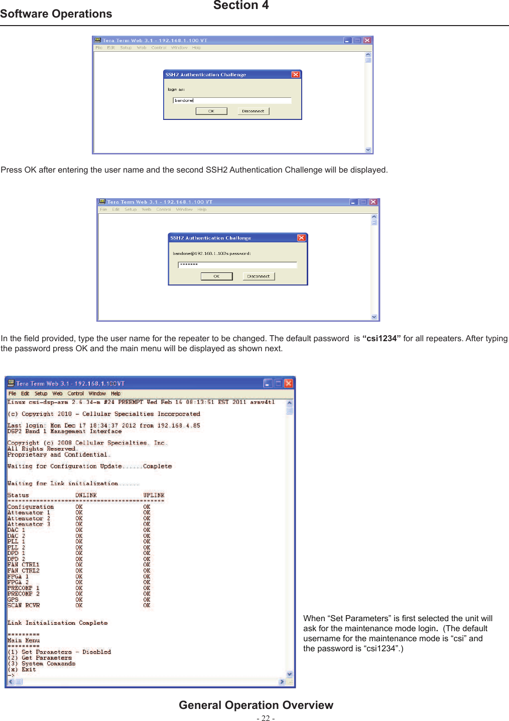
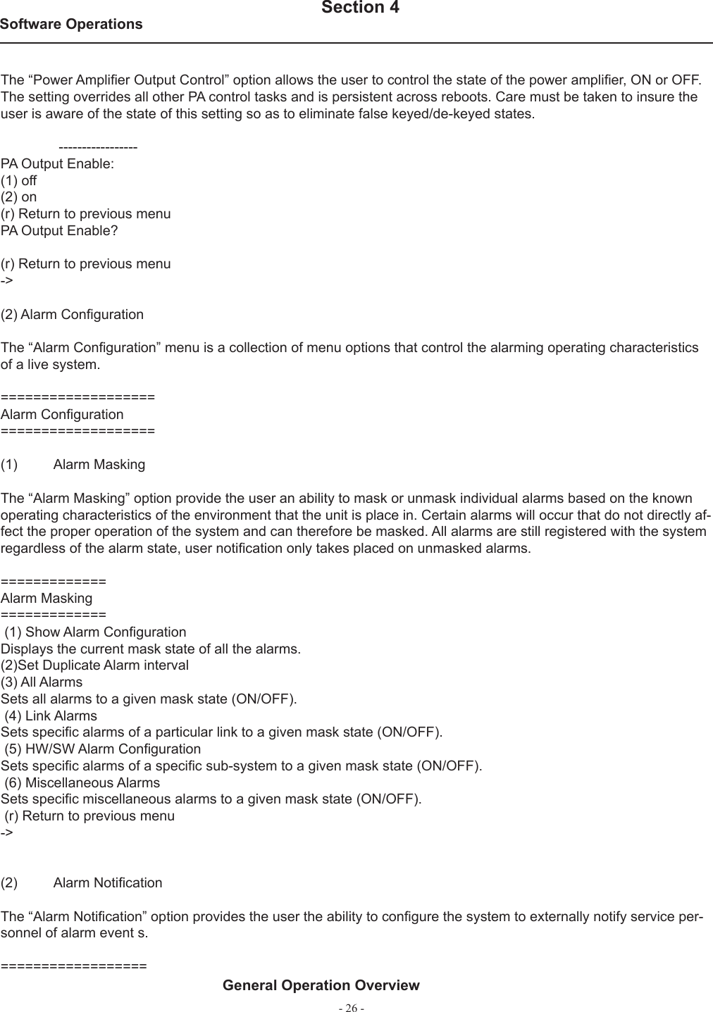
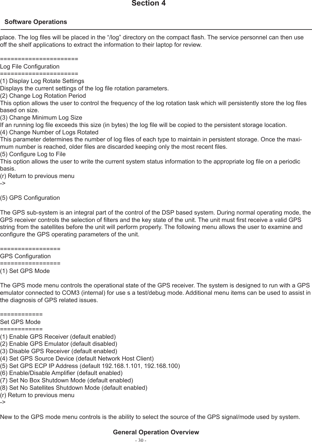
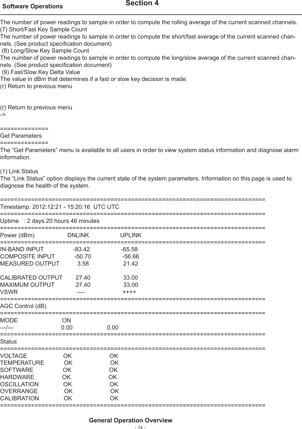
![- 24 -Software Operations Section 4General Operation Overview==============Set Parameters==============(1) Link Confi gurationThe “Link Confi guration” menu is a collection of menu options that control the RF operating characteristics of a live system. ==================Link Confi guration==================(1) Adjust GainThe “Adjust Gain” option allows the user to control the total gain of the system. Valid gain settings range from 55 dB to 90 db. If the user selects to confi gure the downlink gain, the uplink gain will automatically be set to the same value. In order to override this condition, the user will have to select the uplink option and adjust the gain to the desired value.-----------Links:(1) downlink(2) uplink(r) Return to previous menuLink?-----------User Gain:Setting 85.00 dBUser Gain? 85.0Auto Setting Uplink Gain to 85.00 dBTo override, set Uplink gain separately(2) Select Active FilterThe “Select Active fi lter” option allows the user to select the fi lter coeffi cients that have been loaded in the FPGA for test purposes. Please note that in order for this to work properly, the GPS task needs to be disabled otherwise the fi lter selection will be overridden by the current location of the system.----------------FILTER settings:(1) select fi lter coeffi cient(2) show fi lter coeffi cient(r) Return to previous menuFILTER settings?Filter Coeffi cient Tablefi lter index[1] = alB0F0-0fi lter index[2] = alB0C0D0-0fi lter index[3] =fi lter index[4] =fi lter index[5] =fi lter index[6] =fi lter index[7] =fi lter index[8] =](https://usermanual.wiki/Westell/CSIDRACELAPRAW/User-Guide-2115732-Page-23.png)
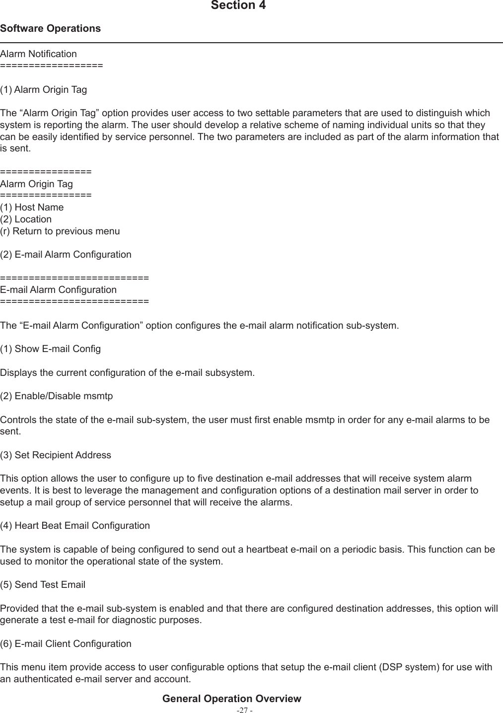
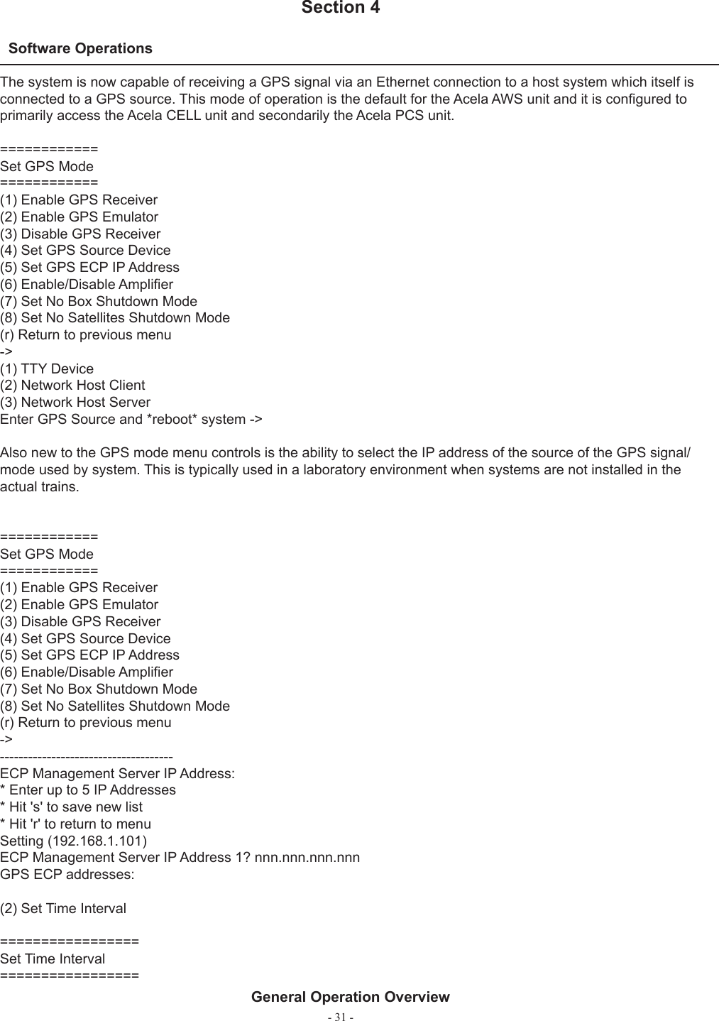
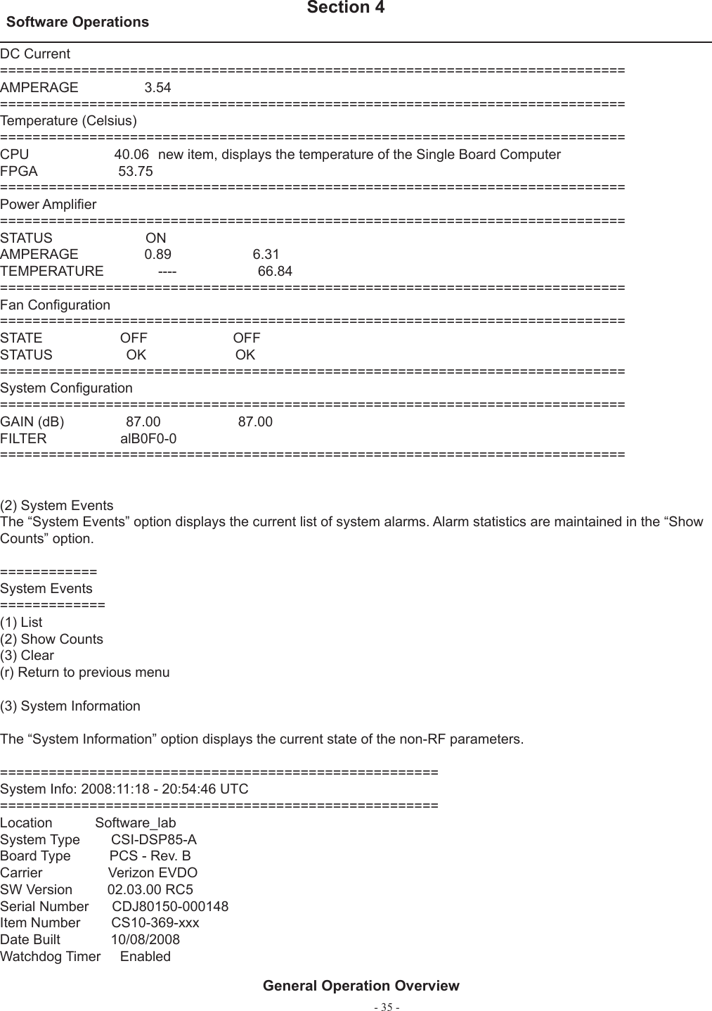
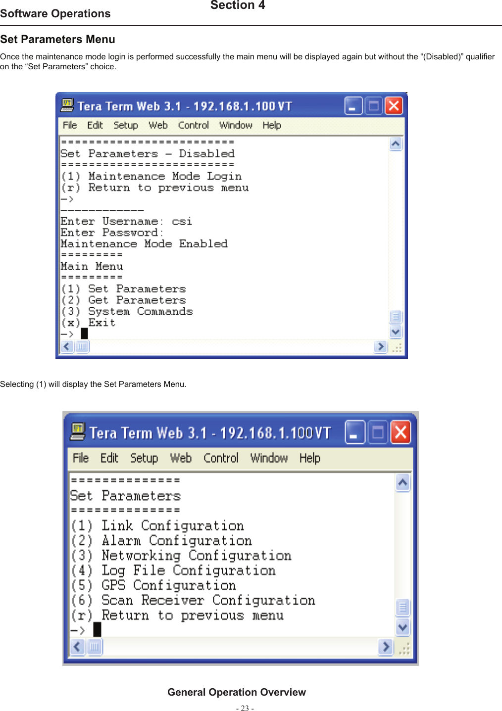
![-25 -Software Operations Section 4General Operation Overviewfi lter index[9] =fi lter index[10] =fi lter index[11] =fi lter index[12] =fi lter index[13] =fi lter index[14] =fi lter index[15] =fi lter index[16] =----------------FILTER settings:(1) select fi lter coeffi cient(2) show fi lter coeffi cient(r) Return to previous menuFILTER settings?select fi lter [1-16](3) Filter ProgrammingThe “Filter Programming” option allows the user to select and load one of the loaded fi lter coeffi cients on the sys-tem. The user will be prompted to select which index the fi lter will be loaded into, one through sixteen or all for test purposes. Please note that in order for this to work properly, the GPS task needs to be disabled otherwise the fi lter selection will be overridden by the current location of the system.-------------Scan USB for fi les? (y,n):File names:(1) alA0B0-0(2) alA0B0C0D0E0F0-WD(3) alB0-0(4) alB0C0-0(5) alB0C0D0-0(6) alB0D0-0(7) alB0F0-0(8) alF0-0(r) Return to previous menuEnter fi le number? Select fi lter ID [1-16] [99 = all] =>-----------==================Link Confi guration==================(1) Adjust Gain(2) Select Active Filter(3) Filter Programming(4) PA Output Control(5) PA Oscillation Shutdown Control(6) PA Oscillation Timer Control(r) Return to previous menu->(4) Power Amplifi er Output Control](https://usermanual.wiki/Westell/CSIDRACELAPRAW/User-Guide-2115732-Page-24.png)