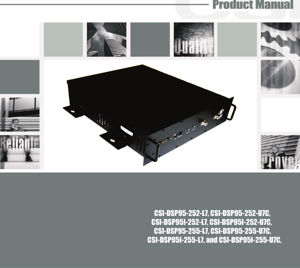
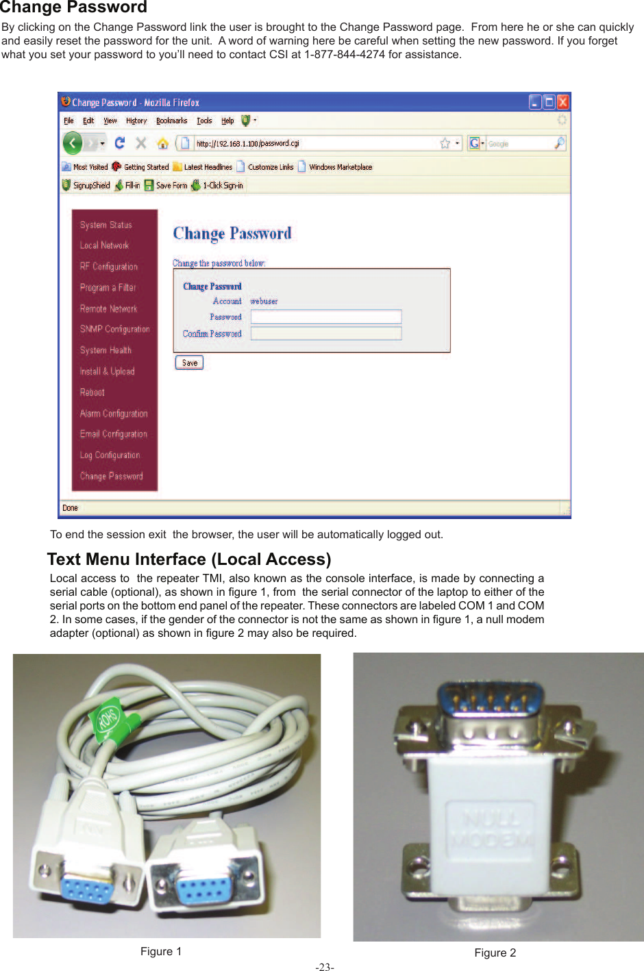
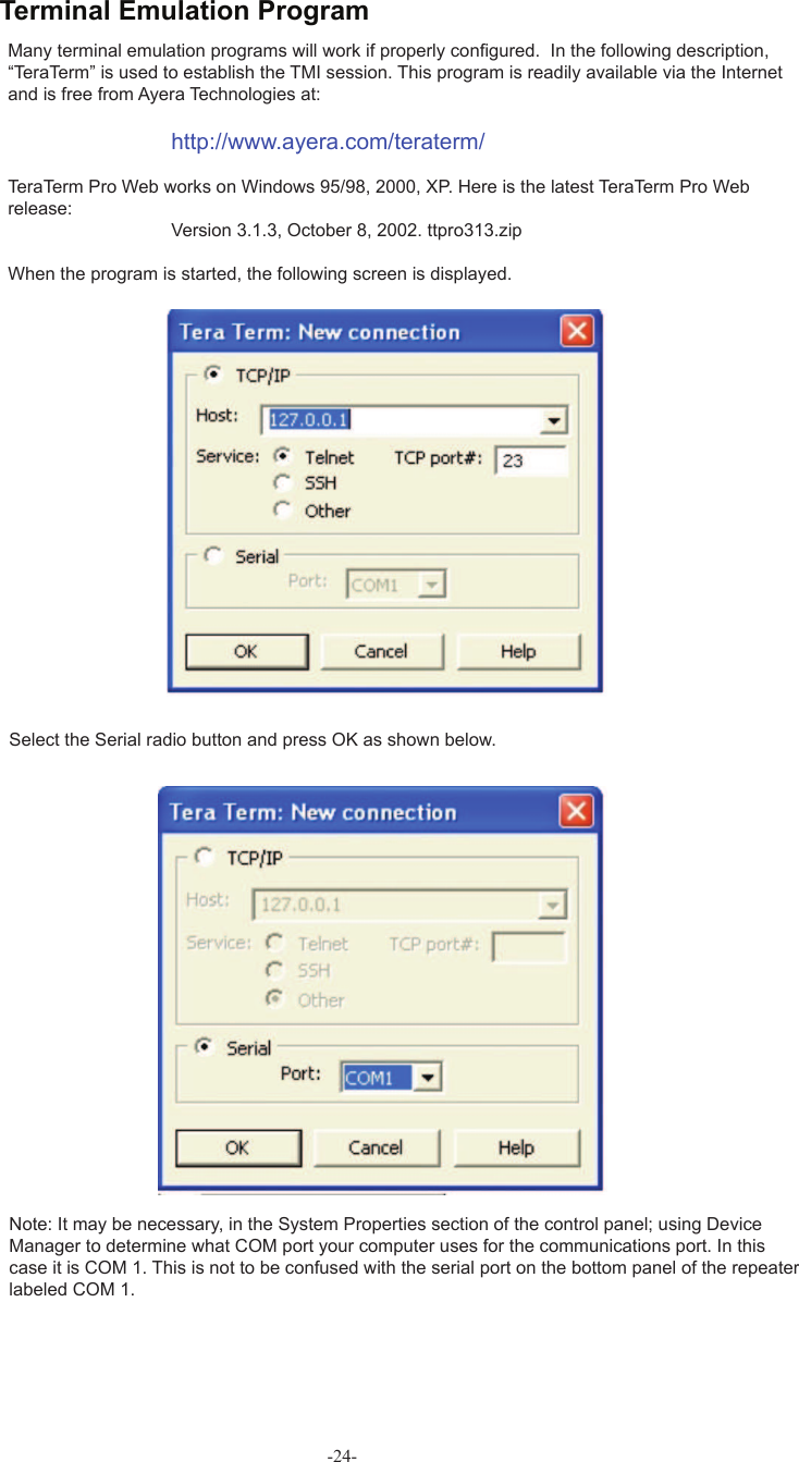
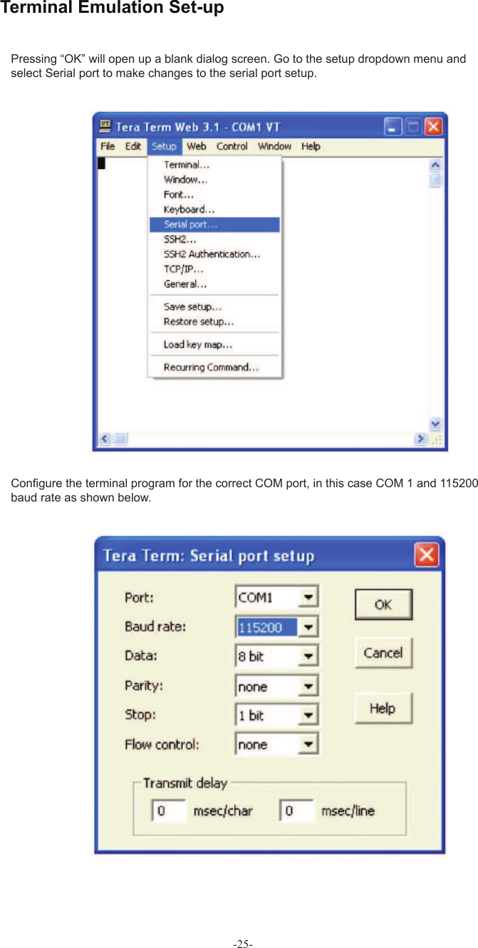
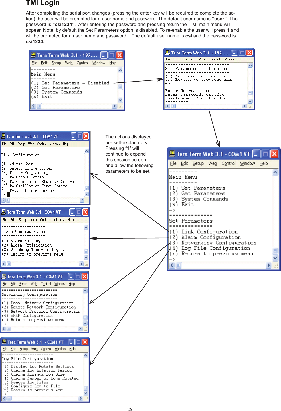
Westell CSIDSP95255U7C DSP95 255 DIGITAL REPEATER LTEC 700 MHz UPPER C BAND User Manual

Westell, Inc. DSP95 255 DIGITAL REPEATER LTEC 700 MHz UPPER C BAND Users Manual

Users Manual

      CSI-DSP95-252-L7, CSI-DSP95-252-U7C,     CSI-DSP95I-252-L7, CSI-DSP95I-252-U7C,      CSI-DSP95-255-L7, CSI-DSP95-255-U7C, CSI-DSP95I-255-L7, and CSI-DSP95I-255-U7C,
-2-
Table of ContentsProduct Registration Information ................................................................................................................... 4Document Purpose / Intended Users.............................................................................................................. 4Application ........................................................................................................................................................ 4Radio and Television Interference .................................................................................................................. 4Safety Guidelines ............................................................................................................................................. 4Important Safety Information .......................................................................................................................... 5Terms used in this manual .............................................................................................................................. 5Product Introduction ........................................................................................................................................ 5Band Plan and Filter Naming Convention ...................................................................................................... 6LTE Filter File Naming Convention ................................................................................................................. 6Functional Overview ........................................................................................................................................ 7LED Indicator .................................................................................................................................................... 7Local Communication Interface Ports ............................................................................................................ 8EIA232 Pin Specifi cations................................................................................................................................ 8USB Interface .................................................................................................................................................... 8Ethernet ............................................................................................................................................................. 8Monitoring & Alarms ........................................................................................................................................ 9System Set-Up Considerations ....................................................................................................................... 9Selection of external attenuators to be used in line with the Antenna Port(s) ........................................... 91:1 Port Confi guration  ..................................................................................................................................... 9Donor Port ....................................................................................................................................................... 10Server Port ...................................................................................................................................................... 10Attenuator Selection Guidelines ................................................................................................................... 10Mounting the Digital Repeater ........................................................................................................................11Wall Mounting  .................................................................................................................................................1119” Relay Rack Mounting  ..............................................................................................................................1119” Four Post Rack Mounting  .......................................................................................................................11Important Installation Notes .......................................................................................................................... 12Installation Tips .............................................................................................................................................. 12Donor Antenna ................................................................................................................................................ 12Indoor Antennas ............................................................................................................................................. 12Optional Accessories ..................................................................................................................................... 12Circuit Operational Description .................................................................................................................... 13Functional Block Diagram ............................................................................................................................. 13Mechanical Specifi cations ............................................................................................................................. 14Environmental Requirements........................................................................................................................ 14AC Power Specifi cations ............................................................................................................................... 14Operating Power Parameters ........................................................................................................................ 15Mechanical Drawing ....................................................................................................................................... 16System Status ................................................................................................................................................. 17Web based GUI Session ................................................................................................................................ 17Local Network ................................................................................................................................................. 18RF Confi guration ............................................................................................................................................ 19Program a Filter .............................................................................................................................................. 19Remote Network ............................................................................................................................................. 20SNMP Confi guration ....................................................................................................................................... 20System Health ................................................................................................................................................. 21Install & Upload .............................................................................................................................................. 21Reboot ............................................................................................................................................................. 22E-mail Confi guration ...................................................................................................................................... 22Alarm Confi guration ....................................................................................................................................... 22Log Confi guration .......................................................................................................................................... 22Change Password .......................................................................................................................................... 23Text Menu Interface (Local Access) .............................................................................................................. 23Terminal Emulation Program ......................................................................................................................... 24Terminal Emulation Set-up ............................................................................................................................ 25TMI Login ......................................................................................................................................................... 26Telnet Session (Remote Access) .................................................................................................................. 28Telnet Session Login ...................................................................................................................................... 29Modem Interface (Remote Access with login) ............................................................................................. 30Additional Tips ................................................................................................................................................ 31Suggested spectrum analyzer setting .......................................................................................................... 33RF Notes .......................................................................................................................................................... 33Industry Certifi cations/Registration Numbers: ............................................................................................ 34Index ................................................................................................................................................................ 35-3-
-4- Product Registration InformationDISCLAIMER: All  information and statements contained  herein are  accurate to  the best  of the knowledge of Cellular Specialties, Inc. (CSI), but Cellular Specialties makes no warranty with respect thereto, including without limitation any results that may be obtained from the products described herein or the infringement by such products of any proprietary rights of any persons. Use or ap-plication of such information or statements is at the users sole risk, without any liability on the part of Cellular Specialties, Inc. Nothing herein shall be construed as licence or recommendation for use, which infringes upon any proprietary rights of any person. Product material and specifi cations are subject to change without notice. Cellular Specialties’ standard terms of sale and the specifi c terms of any particular sale apply.The general safety information in this guideline applies to both operating and service personnel. Specifi c warnings and cautions will be found in other parts of this manual where they apply, but may not appear in this summary. Failure to comply with these precautions or specifi c warnings elsewhere in the manual violates safety standards of design, manufacture, and intended use of equipment. Cellular Specialties, Inc. assumes no liability for the customer’s failure to comply with these requirements: Grounding  This Digital Repeater system is designed to operate from 100-240 VAC and should always   be operated with the ground wire properly connected. Do not remove or otherwise alter the   grounding lug on the power cord. Explosive Atmospheres To avoid explosion or fi re, do not operate this product in the presence of fl ammable   gases or fumes. Lightning Danger Do not install or make adjustments to this unit during an electrical storm. Use of a suitable lightning arrester, such as CSI’s model number CSI-CAP, is very strongly recommended.No User Serviceable Parts Inside HAZARDOUS VOLTAGES ARE PRESENT WHEN THE COVER IS REMOVED. Opening the chassis will void your warranty. If you suspect a malfunction with this product, call your dealer or the Cellular Specialties Support Line at: (603) 626-6677, Toll Free (USA) 1-877-844-4274.Safety GuidelinesThis guide should be applied whenever a need exists to add Digital Repeater capability to an existing system or when this capability is being included with a new installation. Application Document Purpose / Intended UsersThe purpose of this document is to provide a step-by-step procedure to help the experienced technician/engineer install and commission an in-building wireless enhancement repeater system using CSI’s Digital Repeater. Following the procedures outlined will minimize risks associated with modifying a live system and prevent service interruptions. This document assumes the technician/engineer understands the basic principles and functionality involved with Repeater and in-building systems. It is geared to the practical concerns of the installer.The serial number may be found on the label on the bottom panel near the power connectors. Note this number below. Retain this manual, along with proof of pur-chase, to serve as a permanent record of your purchase. MODEL NUMBER   SERIAL NUMBER            PURCHASE DATEPOINT OF SALE COMPANYRadio and Television InterferenceNOTE: This equipment has been tested and found to comply with the limits for a Class A digital device, pursuant to Part 15 of the FCC rules. These limits are designed to provide reasonable protection against harmful interference when the equipment is operated in a commercial environment.  This equipment generates, uses and can radiate radio frequency energy and, if not installed and used in accordance with the instruction manual, may cause harmful interference to radio communications. Operation of this equipment in a residential area is likely to cause harmful interference in which case the user will be required to correct the interference at his own expense. In order to maintain compliance with FCC regulations shielded cables must be used with this equipment. Operation with non-approved equip-ment or unshieled cabled is likely to result in interference to radio & television reception. Changes and Modifi cations not expressly approved by Cellular Specialties can void your authority to operate this equipment under Federal Communications Commissions rules.
-5-   AGC= Automatic Gain Control                  ERP= Effective Radiated Power  APC= Automatic Power Control   FPGA= Field Programmable Gate Array  AUI= Attachment Unit Interface   LED= Light Emitting Diode  CPU= Central Processing Unit                 OIP3= Third-Order Intercept Point   CSI= Cellular Specialties, Inc.                  RF= Radio Frequency  DAS= Distributed Antenna System   SBC= Single board Computer                 DHCP= Dynamic Host Confi guration        SNMP= Simple Network Management Protocol                          Protocol      TMI= Text Menu Interface  DSP= Digital Signal Processing   USB = Universal Serial Bus  EEPROM= Electrically Erasable   UHCI = Universal Host Controller Interface      Programmable read-       only Memory  Antennas used for the purpose of radiating signals indoors are limited to a maximum gain of 3 dBi. The outdoor antenna used for the purpose of communicating to the wireless infrastructure is limited to 14dBi gain, or any combination of gain and loss that equates to 14dB at input. Each antenna must be positioned to observe minimum separation requirements from all users and bystanders. The following guidelines should be used when considering separation distances.INDOOR antennas must be placed such that, under normal conditions,  personnel cannot come within 122 cm (~4.0 ft.) from any inside antenna. Adhering to this minimum separation will ensure that the employee or bystander cannot exceed RF exposures beyond the maximum permissible limit as defi ned by section 1.1310 i.e. limits for General Population/Uncontrolled Exposure.OUTDOOR antenna must be positioned such that, under normal conditions,  personnel cannot approach closer than 183 cm. (~6 ft.). A directional antenna having a maximum gain of 14 dBi is used, precautions should be taken to prevent personnel from routinely passing through the main radiation beam at a distance closer than specifi ed.Product IntroductionTerms used in this manual Important Safety InformationCellular Specialties, Inc. (CSI) developed the DSP85-252, DSP85-255, DSP85I-252 and DSP85I-255 digital repeaters for use within enclosed structures where suffi cient signal from local cell sites to operate cell phones is unavailable. Adequate signal must be available outside the structure as a prerequisite to achieving in-building coverage. The Digital Repeater is connected to an external antenna, usually on the roof, and to one or more internal antennas placed strategically throughout the area where wireless service is desired.The external antenna typically is directional, such as a “yagi”. Internal antennas are typically omnidirectional, although various other types may be used depending on the coverage application. The CSI DSP Repeater amplifi es both the “uplink” (phone to tower) & “downlink” (tower to phone) signals thus facilitating communications to and from the intended wireless infrastructure. With a maximum total of +85dB nominal gain on both the up and down links, gain can be adjusted over a range from +53.5dB to +85dB in 0.5dB steps. Control of the repeater is achieved utilizing a computer connected to com port 1 or 2 or via a Crossover Ethernet cable connected to the Ethernet port. A specifi c fi ltering process modifi es each amplifi cation chain. This process digitally converts the assigned spectrum and then ap-plies digital signal processing (DSP) techniques. DSP is used to create passbands that selects the RF energy passing through either the uplink or downlink paths. After the digital processing is complete, the information is converted back to an analog signal that is applied to the remaining stages of amplifi cation. The resulting signals emitted by the repeater are specifi c to the network service providers’  requirements. If these requirements change, only the DSP confi guration parameters need change in order to adapt. Confi guration parameters are created at the factory and supplied as fi les that may be downloaded to the repeater. The fi lter set confi gurations stored in memory determine the unit’s adaptability to various fi eld applications. The following pages de-scribe the Cellular and PCS band plans as well as the convention CSI uses to identify and store the fi les that make up the fi lter set. All CSI repeaters are shipped with an active fi lter set that is programmed according to the ordering parties’ specifi cations.  In most cases, the installer will not be required to program a fi lter.
LTE Filter File Naming Convention-6-LTE Lower A, B & C Band PlanUp Link (MHz)Down Link (MHz) 728698A0UL698-704DL728-734B0UL704-710DL734-740A1UL698.5-703.5DL728.5-733.5B1UL704.5-709.5DL734.5-739.5AB704 710734 740Up Link (MHz)Down Link (MHz)A2 A3 A4 A5 A6 A7UL698-699DL728-729UL699-700DL729-730UL700-701DL730-731UL701-702DL731-732UL702-703DL732-733UL703-704DL733-734B2 B3 B4 B5 B6 B7UL704-705DL734-735UL705-706DL735-736UL706-707DL736-737UL707-708DL737-738UL708-709DL738-739UL709-710DL739-740746716CC0UL710-716DL740-746C1UL710.5-715.5DL740.5-745.5C7C6C5C4C3C2UL715-716DL744-745UL714-715DL744-745UL713-714DL743-744UL712-713DL742-743UL711-712DL741-742UL710-711DL740-741LTE Upper C Band PlanUp Link (MHz)Down Link (MHz) 746776C0UL776-787DL746-757C1UL776.5-786.5DL746.5-756.5C787757Up Link (MHz)Down Link (MHz)781.5751.5Note: All Variant/Guard Band designators other than 0 are user defi ned custom fi lters.Band Plan and Filter Naming Convention
-7-The CSI-repeater incorporates the following features for convenient operation, access, protection, and control.•  Network Confi guration and Control using  either a webpage style GUI through   any standard  browser or a menu driven user interface using the serial port.   (Note: GUI does not require Internet access.) •  User Gain Control (affects all passbands)•  Automatic Gain Control•  Automatic Power Control•  Oscillation Protection•  Over Drive Protection (P.A. limiting)•  Under/Over Voltage Protection•  Fault Protection•  Alarm Notifi cation - Local/Remote•  Upgrade Support - Local/Remote•  External Interfaces - USB/Ethernet/Serial•  Re-loadable fi lters - Local/Remote•  Web-based monitoring and control - Local/Remote•  Persistent Status and Error informationAutomatic safety precautions are built into the amplifi er system. In the case of a catastrophic system event, a shutdown circuit is incorpo-rated that will disable all emissions should the uplink input or downlink input be overdriven or should an oscillation or output overpower event occur. The amplifi er will periodically attempt to recover from the detected condition automatically. Warning light indicators are as follows:When a boot up  is complete and no alarm conditions exist, the LED indicator will be illuminated green.  Should a fault condition develop the LED will illuminate red and the user may check the status page of the GUI for the nature of the fault.* Functional Overview LED Indicator*Note:  During Power up, the repeater will require a approximately three minutes for             the internal computer to boot up. During this time the LED on the front panel may light             and go out several times.            Do not unplug the unit while it is in the boot up process!
-8-EIA232 Pin Specifi cationsThe diagram above is for reference only, it’s intended to provide a quick source for pinout informa-tion in the event it should be necessary to adapt your serial cable because of an unusual connector confi guration.  In the vast majority of cases this information will not be needed.To allow monitoring and control, the repeater is equipped with four ports that provide external communication access (1 Ethernet CAT-5, 2 DB-9 serial, and 1 USB). The Ethernet, CAT-5 port is provided as a primary communications port to the PC. One serial interface provides communications to local PC and the second to an external modem when provided. The  USB interface provides a means to download fi les from a memory device and may also be used by an external modem.  The DB-9 pin assignments conform to the standard Electronic Industries Association (EIA232) specifi cation. A diagram of the pin descriptions is provided on this page  for reference.Connecting a null modem cable to one of the COM ports and using a terminal emulation program with a PC will allow communication to the control processor’s Text Menu Interface (TMI). See command line interface section for further detail.The Universal Serial Bus (USB) interface conforms to Intel’s Universal Host Controller Interface (UHCI) version 1.1 dated March 21, 1996. This interface will support data transfer rates up to 12 Mbps and can be used for software updates and fi lter fi le uploads.Local Communication Interface Ports USB InterfaceThe Ethernet AUI conforms to IEEE 802.3 and is capable of supporting 10/100 Mbps communications speeds. This port is used to provide access to the GUI.Ethernet
-9-All cables should be checked for shorts and opens. Also verify that there are no cables with loose or poor connections. RF leakage could cause oscillation to occur under some conditions.The rooftop antenna (Donor Antenna), if directional, should be checked for proper alignment along the calculated compass heading. Typically, the directional antenna would be aimed at the same site that your handset uses, but it may not always be so. It is critical the installer contact the service provider for information on, and approval of, the site he or she has selected before the system is turned on.If cables and alignment are acceptable and a problem persists, it may be necessary to use a spectrum analyzer to examine the signal environment in which the unit is operating. The existence of strong  adjacent channel signals within the frequency band(s) can cause the AGC to reduce the amplifi er’s gain or cause alarms. In some cases additional fi ltering or attenuation might be required to reject these unwanted signals. In some instances, the donor antenna can be reoriented horizontally, to place the interference source in an antenna pattern “null”. There also may be some cases where the interference from outside signals is so great that they cannot be fi ltered or oth-erwise reduced or eliminated without expensive and possibly prohibitive measures. In these cases it may not be practical to use the CSI repeater for providing coverage to these sites.There are no physical connections provided to specifi cally communicate system or alarm status. This information is embedded in the information accessible via the communication ports described earlier. Monitoring & AlarmsSystem Set-Up ConsiderationsSelection of external attenuators to be used in line with the Antenna Port(s)HIGHLOW/COMETHERNETUSBSTATUS 2STATUS 1ACOMHIGH LOW/COMSERVER DONORInput:  One dual band duplex port, from the dual band donor.Output:  One dual band duplex port, to the DAS.1:1 Port Confi guration
-10-If a CSI repeater is installed in an area with very strong desired and/or undesired signals, it is important to ensure that the overall signal levels are optimized to be within the best operating range of the repeater.  Additionally, de-sensing of a nearby base station site must be avoided.  These goals can be accomplished by properly attenuating the antenna port(s) in the path of the donor antenna(s).  In effect, one can imagine that the particular repeater deployment is electrically moved farther from the base station using attenuators that are equivalent to increasing the path loss from the donor antenna to the base station. The following potential outcomes result from the use of attenuators on the donor port(s) of the unit:  Uplink output power, as reported by the repeater, is reduced by the value of the attenua-tion, protecting nearby base stations.  Downlink signal to noise ratio is high at the point of the attenuator, resulting in slight but negligible reduction in downlink performance. Other performance is essentially unchanged.Donor PortServer port attenuation may also be necessary, particularly where a powered DAS is present.  The selection guidelines below apply to both server and donor ports.  In order to properly measure uplink signal strength, a signal generator should be used.  If a signal generator is not available, placing a test call while under the server antenna with the least path loss to the repeater should provide reasonable data.The following potential outcomes result from the use of attenuators on the server port(s) of the CSI repeater:  Downlink output power, as reported by the unit, is reduced by the value of the attenuation.  Uplink incoming power from the DAS is reduced, along with potentially strong and/or harmful out-of-band signals (including noise) that are generated by the DAS.Server PortAttenuator Selection GuidelinesAccurate attenuator values need to be chosen to ensure that the maximum total power (higher of Composite or In-Band Input) applied to the donor and server port(s) does not exceed the following thresholds:                              Input Signal      Max Gain                Input Signal    Max Gain                      <-45 dBm         85 dB    -32.2 dBm                   69 dB                                        -44.3 dBm        84 dB    -31.4 dBm                   68 dB                                        -43.6 dBm         83 dB     -30.6 dBm                        67 dB                                        -42.9 dBm          82 dB     -29.8 dBm                             66 dB                                        -42.2 dBm          81 dB     -29 dBm                          65 dB                                        -41.5 dBm          80 dB     -28.2 dBm                        64 dB                                        -40.6 dBm         79 dB     -27.4 dBm                        63 dB                                        -39.7 dBm          78 dB     -26.6 dBm                        62 dB                                        -38.8 dBm          77 dB     -25.8 dBm                        61 dB                                        -37.9 dBm          76 dB      -25 dBm                       60 dB                                        -37 dBm          75 dB      -24.4 dBm                            59 dB*                                        -36.2 dBm          74 dB      -23.8 dBm                            58 dB*                                       -35.4 dBm          73 dB      -23.2 dBm                            57 dB*                                        -34.6 dBm         72 dB      -22.6 dBm                            56 dB*                                        -33.8 dBm          71 dB      -22 dBm                     < 55 dB*                                       -33 dBm          70 dB        *We recommend padding this level due to potential for fl uctuating signal.     -25 dBm is the maximum input signal level that should be applied to the repeater, even if the gain is lower than 55 dB. Input signals exceeding these thresholds will result in composite input attenuation, called “ADC Protect” (Analog to Digital Converter Protection).  Output power is reduced whenever the above thresholds are exceeded by reducing the gain by 1dB for each 1 dB that the threshold is exceeded.  ADC Protect should not be confused with AGC (Automatic Gain Control), which reduces gain to prevent In-Band (measured) output power from exceeding the specifi ed maximum output level. To determine the total power applied to the donor and server ports, please reference the “Composite Input” values as reported in the Web (“System Status”) or Menu (“Link Status”) interfaces (depicted and explained later in this manual).  Large delta’s between in-band and composite input signals:Care should be taken to isolate the best donor site to ensure the least possible delta between in-band and composite downlink signals. If the (downlink) composite input exceeds the in-band input by more than 3 dB for the LTE band  the maximum output power will be reduced.
-11- Mounting the Digital RepeaterThe following diagrams illustrate the methods for mounting the repeater in a typical wall or rack installation.  Brackets provided serve for both options.Step 2: Mark the location of the wall anchoring            holes and drill. The wall anchoring            system you use for the repeater will            need to be able to support at least 46             lbs/ 21kg.  Install wall anchors and             hang repeater as shown.Step 1: Install the wall mount brackets as shown in the drawing to the right. Wall Mounting 19” Relay Rack Mounting Mount the repeater as shown and secure front panel with screws. Note: the CSI digital repeaters must be supported in the 19” Relay Rack system with a shelf. Do not rely on the front panel mount exclusively to support all the weight of the unit.Install slid brackets on repeater as shown in the tapped holes provided. Slid repeater into the receiving brackets and secure with screws. The repeater must be supported in the rack system with slide rail. Do not rely on the front panel mount exclusively to support all the weight of the unit.19” Four Post Rack Mounting
-12-A complete line of accessories is available from Cellular Specialties, Inc. Check with your CSI distributor for any additional items needed.  Below are just a few examples suitable for most in-building needs.•Directional Couplers       6dB - model number: CSI-DC6/700-2.7K/N     10dB - model number: CSI-DC10/700-2.7K/N     15dB - model number: CSI-DC15/700-2.7K/N     20dB - model number: CSI-DC20/700-2.7K/N     30dB - model number: CSI-DC30/700-2.7K/N•Outside Donor Antenna                 Panel - model number: CSI-AP/698/2.2K/7-10 •UPS      Battery backup, 2 hr Single band      1 hour dual band - model number: CS48-985-600 Battery backup, 4 hr Single band 2 hour dual band - model number: CS48-985-601•Power Dividers       2:1 - model number: CSI-SPD2/700-2.7K/N              3:1 - model number: CSI-SPD3/700-2.7K/N      4:1 - model number: CSI-SPD4/700-2.7K/N   •Grounding Kit - model number: CSI-GKIT                 •Lightning Arrestor - model number: CSI-CAP•Inside Omnidirectional Antenna      Quad-band - model number: CSI-AO/700/2.7K/3Optional Accessories •        Inadequate isolation between the outside and inside antennas may cause regenerative feedback in the system. This feedback can cause the amplifi er to emit a continuous signal at maximum amplitude and, in some cases, interfere with normal operation of the donor site. Careful consideration of the layout and placement of the system is imperative to minimize this possibility and to minimize the amount of signal leaking from the building. See installation tips below for general guidelines.•  The installer should refer to the Safety Guidelines section on page 4 and the Important Safety Information section on page 5 for proper antenna selection and installation. To avoid serious injury or death and damage to the repeater, do not install donor or server antennas near overhead power lines or high power components.   Allow enough distance so that if antennas should fall they will not come in contact  with those components.•  Close proximity  to the donor or server antennas with the repeater in operation may expose the user or installer to RF fi elds that exceed FCC limits for human exposure.WARNING!  AMPLIFIER OR HANDSET DAMAGE MAY OCCUR IF A HANDSET IS CONNECTED DIRECTLY TO THE REPEATER OR THE COAX THAT LEADS TO THE REPEATER.Important Installation NotesDonor Antenna1.  Accurately determine  the azimuth to the donor cell site . Obtain the donor site information and approval from the            service provider/carrier.2.  Ensure that the radiation path to the donor cell site is as unobstructed as possible.3.  Mount the donor antenna at or toward the edge of the roof, in the direction of the donor site. Try to avoid having the RF             signal from the donor pass above the location(s) of the service antennas.  Normally the service antennas will be behind           and below the donor antenna if viewed from above. This approach will help avoid interference and feed back both, to and          from the service antennas. 4.  Normally mounting the donor antenna higher will allow a less obstructed path to the donor site.  However, in high traffi c         metro areas avoid mounting the donor antenna any higher than necessary as the quality of the donor signal may start to         become less stable and it is more likely to encounter adjacent channel interference.5.  When possible shield the donor antenna’s back side by locating it so that any HVAC units and/or penthouse structures are         behind the antenna relative to the donor cell site location.Installation TipsIndoor Antennas1.  Use omnidirectional antennas (see optional accessories) indoors, and locate them centrally with respect to the intended         coverage area to minimize signal leakage to the outside. Use directional antennas indoors only in special cases when higher         gain and directionality would be helpful and RF exposure limits will not be exceeded.2.  To avoid repeater uplink overload and gain limiting mount the indoor antennas away from areas where mobile subscribers          frequently use their phones such as desks or dispatch areas. •Cross Band Couplers   Quad band Rack Mount: CSI-CM250-7/C/AW/P  (700 LTE, Cell, AWS and PCS)  Quad band Wall Mount: CSI-CBC/696-2170/N   (700 LTE, Cell, AWS and PCS)  Tri band Rack Mount: CSI-CM250-U7C/C/P  (700 Upper C LTE, Cell and PCS)      Tri band Wall Mount: CSI-CBC21/740-1990/N         (700 Upper C LTE, Cell and PCS)   Tri band Rack Mount: CSI-CM250-L7AB/C/P  (700 Lower A/B LTE, Cell and PCS)  Tri band Wall Mount: CSI-CBC21/696-1990/N  (700 Lower A/B LTE, Cell and PCS)
-13-The repeater uses a single down-conversion/up-conversion scheme. There are multiple  RF amplifi er stages prior to each down-converting mixer. The down-converting mixers are followed by a single IF amplifi er. A Digital Signal Processor block then processes the resultant digitized IF signal that was previously generated by an Analog-to-Digital Converter. The processed (fi ltered) digital signal is fed to a Digital-to-Analog converter and then up-converted to RF. A driver amplifi er and a fi nal power amplifi er make up the fi nal gain stages before application to the diplexer. The maximum total system gain (diplexer input to diplexer output) is nominally 85 dB for either the downlink  or the uplink paths with both links having independent manual and automatic gain controls (AGC). AGC reacts to analog power detection on both the input and output of the uplink and downlink RF chains. A control algorithm continu-ously monitors these detected values and dynamically adjusts various gain stages  such that the net system gain value, entered manually, is maintained without either exceeding FCC parameters or overdriving the A/D converters. Circuit Operational Description Functional Block DiagramUpon detection of oscillation the unit will shut down.  After a “short duration” of 30 seconds the unit will attempt normal operation.  If no continued oscillation is occurring the unit will stay on. However, if oscillation is still occurring, the repeater will remain shut down and retry 1 additional time in the “short duration” loop.  If after these two “short duration” retries, the oscillation is still detected, it will turn off again and wait a “long duration” period of 10 minutes.  If after 6 “long duration” retries, oscillation continues,  the unit  will go into a “disable duration” of 24 hours. It will continue in the “disable duration” loop and retry every 24 hours.LED on the front panel display provide immediate visual indications of the unit’s primary power and major or minor alarm status. The repeater features automatic shutdown protection, as a safety measure, should excessive drive be applied to the input or an oscillation condition occur. When in a protected mode, a control algorithm determines the appropriate method of recovery to a normal, previously defi ned state, or maintains the protection until manually reset.Indoor Antennas continued3.  To determine the quantity and locations of indoor antennas, use an appropriate phone’s signal meter to determine areas of          weak signals. These are the approximate areas where indoor antennas may be needed. Also be aware the signal from an          indoor antenna, in most cases, can be expected to penetrate about two standard offi ce sheetrock type walls to reach users.          After two walls or if the walls are made of other materials, it may be necessary to split the available signal and add more          antennas.
-14-Mechanical Specifi cations AC Power Specifi cations Environmental RequirementsParameter    Specifi cation  NotesColor        Satin BlackParameter              Specifi cation  Notes AC Voltage                             100 - 240 VAC  External Power Supply AC Power Frequency  47 - 63 Hz  Weight  31.0 lbs / 14.1 kg  Thermal Management                Fan Cooled  Surface Coating   Powder Coat  AC Current 2.0 Amps  @ 120 VAC  1.0 Amps  @ 230 VAC Repeater SizeHeight    5.25 in.                           3RUWidth    19.00 in.Depth    20.28 in.     Heat Output                              700 BTU/HrParameter             Specifi cation           Notes Relative Humidity  5% to 95%  Non-condensing Temperature Range                  0° to 50° C                                              (32° to 122° F)
-15-Operating Power Parameters OIP3  Linear Output Power                +33 dBm max (CSI-DSP85-252 Down Link)           LTE +32 dBm                                                     (CSI-DSP85-252 Up Link )            + 30dBm max Noise Figure (Avg)       6.0 dB   At Maximum Gain   Parameter      Specifi cation  Notes Maximum RF input Power          +10 dBm without damage Linear Gain   85 dB                  Factory Calibrated Gain Pass Band Ripple    +/-1.5 dB  Automatic Gain Control           30dBmax range        In 0.5 dB steps Manual Gain Control     53.5-85 dB              In 0.5 dB steps RMS Vector Error (EVM)    3% max  TDMA,EDGE,W-CDMA,CDMA2000 CDMA RHO    0.98 min  CDMA2000, 1x-EVD0 Spurious Emissions & Applicable Documents FCC  -13 dBm max  Per FCC part 2, 22, 24 Industry Canada  -13 dBm max Propagation Delay        <2.5 usec   Input VSWR (Typ)                         <2.0:1 + 41 dBm Connectors   N-Female              LTE +29 dBmLinear Output Power                 + 37 dBm max (CSI-DSP85-255 Down Link)          LTE +36 dBm                                                     (CSI-DSP85-255 Up Link )             30dBm maxLTE +29 dBm(CSI-DSP85-252 Down Link)  (CSI-DSP85-252 Up Link)  (CSI-DSP85-255 Up Link)  + 51 dBm(CSI-DSP85-255 Down Link)  Measured with 2 CW tonesat 14 dBm/tone+ 41 dBm+ 57 dBm Measured with 2 CW tonesat 14 dBm/tone
-16-Mechanical DrawingHIGHLOW/COMETHERNETUSBSTATUS 2STATUS 1ACOMHIGH LOW/COMSERVER DONOR
-17-When  login is complete the user is brought to the system status page. The links shown in the navagation box on the left are activated by clicking on them. Primary access to the repeater is  gained using a LAN connection and a web browser program such as Firefox by Mozilla, or Internet Explorer from Microsoft.  The repeater ships with the default IP address of 192.168.1.100, but it can be changed later if required. If connecting directly to the repeater from a laptop or PC with a crossover CAT-5E cable or over a LAN the user types the IP address of the repeater into the browser address line to connect. (Note: Most users will need to update the TCP/IP settings on their computer to enable connection to a host that has a static IP.  Select “Use the following IP Address” and enter the IP Address as follows: 192.168.1.x, where “x” = any number from 2 to 254 inclusive other than 100. The subnet mask is 255.255.255.0.  Questions pertaining to these settings should be referred to the user’s IT depart-ment or you may refer to the Additional Tips section at the end of this manual.)  When connection is made the user will be prompted for a user name and password. For the purpose of the GUI ses-sion, the default user name is webuser and the password is csi1234.  This can also be changed as required. Internet access is not required to use the GUI.  (Note: If you are connecting using a laptop, verify that your Ethernet port is powered.  Some laptops will not allow Ethernet connection when on battery power. If this is the case with the laptop you are using you will need to plug it in or update the power settings.)System Status Web based GUI Session
-18-If the user selects  Local Network from the  System Status page, the following screen is displayed and from here network confi guration can be modifi ed as required. The default is set to Static. Check with your IT department for explanation and approval of the DHCP and DHCP Server options you plan to use before you select them. *NOTE:  In units with software version 2.2.4 or prior, only letters, numbers and underscores are acceptable nomenclature.  In units with software version 2.3.0 and up, Underscores are not acceptable; however, hyphens are acceptable.After any changes are made press the refresh button to review the fi elds and ensure the change made is correct. Note: changing network settings will cause the current TCP/IP connection to fail because the change will  take effect immediately. From here the user may return to the System Status screen or click on the other options. Local Network
-19-If the user would like to modify RF confi guration click on the words  RF Confi guration in the navigation box and the screen below is displayed.The user inputs the gain value desired. Gain values from 53.5 dB to 85.0 dB may be selected. The repeater will not allow the user to set values outside this range. If a new fi lter set is required, the new fi lter may be selected from the “ Program a Filter page” below.The user may select the desired fi lter by pressing the band/sub-band and  modulation selection buttons. Undesired bands/sub-bands if lit will require the user to manually “deselect” them before programming.   Pressing the Program button will complete the selection and load the desired fi lter. The time required to complete this process will take just a few moments.  Note: If the fi lter desired is not currently in the unit, additional fi lters along with instructions on how to load them are available by contacting CSI.RF Confi gurationProgram a Filter
-20-To change SNMP settings click  SNMP Confi guration in the navigation box, the screen below will be displayed. If the user is not well versed in Simple Network Management Protocol he or she should check with their IT professional for proper setting requirements.Remote NetworkSNMP Confi gurationIf the repeater includes a USB modem kit, click on  Remote Network in the navigation box and the screen below is displayed. Highlight the carrier on whose network the repeater and modem will be confi gured and click the Change Settings button. Refer to the documentation included with the modem kit for additional information on confi guring the modem. If the repeater is connected to an ethernet device for remote access and/or monitoring, this feature must be disabled.
-21-By clicking  System Health the current state of the repeater can be reviewed.Should a software install or upgrade be needed it can be done from the  Install & Upload screen shown below. As with the other screens it can be reached by clicking the words in the navigation box. Contact CSI for updates and instructions.System HealthInstall & Upload***The user may clear LED indicators, alarms and the  Event Log by clicking the Clear Log button.******* If required, visit the “System Health” screen and click on “Trigger Test Alarm” and wait for confi rmation that the Service Provider representative that is responsible for monitoring the repeater has been notifi ed of the alarm. Be sure to “Clear All Logs” prior to logging out of the Web Interface.****
-22-If a reboot of the repeater becomes neces-sary click on the Reboot option in the navigation box and the  Reboot page is displayed.RebootThe Log Confi guration page provides the user with the means to modify three aspects of how log fi les are created and stored as shown below.Log Confi guration Alarm Confi gurationThe Alarm Confi guration page allows the user to specify what events will trigger an alarm. *NOTE:  Letters, numbers & hyphens are the only acceptable nomenclature for the Location fi eld and hyphens may not be used as the fi rst or last character.  E-mail Confi gurationE-mail Confi guration page allows the user to enter up to fi ve E-mail addresses to which the repeater can send specifi ed alarm messages when the repeater is connected via ethernet or wireless modem and E-mail Alarm Notifi ca-tion or Remote Networking are enabled.  *NOTE:  In all fi elds the software will not allow the user to enter invalid characters.
-23-To end the session exit  the browser, the user will be automatically logged out. Figure 1 Figure 2Local access to  the repeater TMI, also known as the console interface, is made by connecting a  serial cable (optional), as shown in fi gure 1, from  the serial connector of the laptop to either of the serial ports on the bottom end panel of the repeater. These connectors are labeled COM 1 and COM 2. In some cases, if the gender of the connector is not the same as shown in fi gure 1, a  null modem adapter (optional) as shown in fi gure 2 may also be required.Text Menu Interface (Local Access)By clicking on the Change Password link the user is brought to the Change Password page.  From here he or she can quickly and easily reset the password for the unit.  A word of warning here be careful when setting the new password. If you forget what you set your password to you’ll need to contact CSI at 1-877-844-4274 for assistance.  Change Password
-24-Many  terminal emulation programs will work if properly confi gured.  In the following description, “TeraTerm” is used to establish the TMI session. This program is readily available via the Internet and is free from Ayera Technologies at:    http://www.ayera.com/teraterm/TeraTerm Pro Web works on Windows 95/98, 2000, XP. Here is the latest TeraTerm Pro Web release:    Version 3.1.3, October 8, 2002. ttpro313.zipWhen the program is started, the following screen is displayed.Select the Serial radio button and press OK as shown below.Note: It may be necessary, in the System Properties section of the control panel; using DeviceManager to determine what COM port your computer uses for the communications port. In this case it is COM 1. This is not to be confused with the serial port on the bottom panel of the repeater labeled COM 1.Terminal Emulation Program
-25-Pressing “OK” will open up a blank dialog screen. Go to the setup dropdown menu and select Serial port to make changes to the serial port setup.Confi gure the terminal program for the correct COM port, in this case COM 1 and 115200 baud rate as shown below.Terminal Emulation Set-up
-26-After completing the serial port changes (pressing the enter key will be required to complete the ac-tion) the user will be prompted for a user name and password. The default user name is “user”. The password is “csi1234”.  After entering the password and pressing return the  TMI main menu will appear. Note: by default the Set Parameters option is disabled. To re-enable the user will press 1 and will be prompted for a user name and password.   The default user name is csi and the password is csi1234.The actions displayed are self-explanatory. Pressing “1” will continue to expand this session screen and allow the following parameters to be set.TMI Login
-27-After selecting option 1, downlink, the current user gain is displayed and the option to change it is accomplished by typing the desired gain at the prompt. The user is then returned to the previous menu.Each “Set Parameter” selection, when chosen will be expanded to allow changing or setting of that parameter. For example from the Link Confi guration menu on the previous page, selecting 1 - Adjust Gain will display the menu shown below.
-28-All the other options operate in much the same way. Some of the options will offer the user addi-tional selections and will be self-explanatory. Below is one example of these additional options, the one shown below is the result of selecting (3) Filter Programming. Note: Graceful session termination is important. Use Disconnect under the fi le dropdown menu to terminate a session, otherwise the port may become disabled and force the system to be rebooted.Remote access to the repeater may be gained through a LAN connection and a terminal emula-tion program for TCP/IP. As with the serial connection, many terminal emulation programs will work, if properly confi gured.  In the following description, “TeraTerm” is used to establish the Telnet session. Also, it will be required that the network confi guration of the computer and the repeater being controlled be set up with the same Sub Net and Sub Net Mask in order to establish a link. In other words, the IP addresses of both the computer used and the repeater must use the same group of IP address number sets. For example, the repeater ships with the default IP address of 192.168.1.100 and a Sub Net Mask of 255.255.255.0. In order to connect, the computer to be used for the link would normally need an IP address of something like 192.168.1.12 with a Sub Net Mask of 255.255.255.0, the same Sub Net Mask as the repeater. In this example note: the last digit of the IP address may be any number except 1,100 and 255.  Confi guring your PC is normally fairly straight forward but it does vary somewhat with the operating system involved.  If you require assistance, contact your IT department and they will be able to set up your PC for you or you may review the Additional Tips Section at the end of the manual.When the TeraTerm program is started, the following screen is displayed. Change the default host IP address to the IP address of the repeater to be controlled. In the case of a new install, the default address is 192.168.1.100 and has been assigned at the factory. Select the service Telnet. The TCP Port must be 23.  Telnet Session (Remote Access)
-29-Pressing the “OK” button will bring the user to the following screen, which will require the user to log in.  The default user name is “user”. The default password is “csi1234”.In the fi eld after the prompt type the user name and password. After typing the password press the enter key and the main menu will be displayed as shown next. Telnet Session Login
-30-Telnet and serial sessions both provide access to the same Text Menu Interface. We have already shown many of the options available and all are self explanatory, so they will not be repeated. A modem can also be used to gain remote access to the unit provided the repeater has been prop-erly equipped. A selection of modems is available as an option. If the modem requires a SIM card for activation, special requirements must be met for the SIM card to become fully functional, con-tact the service provider. In addition, an IP address must be obtained and entered into the repeater.Once the modem has been installed and activated, it can be accessed from any terminal emula-tion program just as in the serial and Telnet examples provided earlier.  Access response time will depend on many factors, some of which are:  •  Quality of the connection (RF signal in the case of wireless modems)  •  Technology (CDMA, EDGE, GPRS, etc.)  •  Network congestion (Throughput)When a connection has been established,  the same login screen shown in both the serial and Telnet examples is presented.Modem Interface (Remote Access with login)
-31- Instructions to change  TCP/IP settings on your Windows computer.Click in the Network Connections Icon in the Control Panel. See below.Right click on Local Area Connection - and select “Properties”.Scroll down to “Internet Protocol (TCP/IP) and click on the “Properties” button.Additional Tips
-32-If you are set up to use DHCP, the window shown below will be displayed. Select “Use the following IP address:” and enter “192.168.1.2.”  The subnet mask should automatically populate to “255.255.255.0”.Nothing else will need  to be chosen or entered. Click “OK”, then “OK again and retry connection.A crossover Ethernet cable (supplied) must be used for Web Interface access.  As a reminder, you must verify the Ethernet port on your laptop is powered. If your laptop is on battery power, the Ethernet port may be inactive by default.  If this is the case simply plug in the laptop to a 110vac source or change the power settings to enable the Ethernet port when the laptop is using battery power.
-33-When   troubleshooting RF issues,  and when surveying challenging RF en-vironments, it’s important to have a spectrum analyzer capable of measur-ing the frequency that you are working with.  An attenuator should be used to protect the input, when connected to a source of RF power such as the repeater or a powered DAS.Both Uplink and Downlink should be measured.  Downlink should be measured on the donor cable and at the output (server) port of the powered up repeater, and Uplink at the lead from the DAS (on fi ber/powered DAS’s, where the lead would connect to the server port on the repeater) and at the donor port with the repeater powered up.  Measurements may also be necessary at server antenna locations.  Your spectrum analyzer will need to be equipped with a whip antenna for this. Resolution Bandwidth (RBW) should be set at 200 kHz for GSM and 1 MHz for CDMA.  If you cannot select these values, the closest available values should be used.  Video fi lter should be about one tenth of RBW.  Other settings like span are whatever is appropriate.  One should also make sure that there are no signals above the top of the screen. If you cannot see an adjacent out of band signal when using the 1 MHz RBW fi lter, you can decrease the RBW, to see the close-in-frequency sig-nals.  Be sure to set the RBW back when you want to measure the power level. Suggested spectrum analyzer setting RF NotesTo prevent overload of the DSP input stages, the maximum measured level of in-band or out of band signals should be less than -50 dBm when the DSP gain is set to 85 dB, -40 dBm when set to 75 dB, etc.  This applies when there is one dominant signal and applies TO BOTH THE DOWNLINK AND UPLINK.  If there are two dominant signals, and the gain is set to 85 dB, then the level of each signal should be kept to less than -53 dBm.  With three signals, each should be less than -55 dBm.  With ten signals each should be less than -60 dBm.  This lat-ter reduction prevents the composite power of the multiple signals from exceed-ing an acceptable level.  Add fi xed attenuators in line with the donor antenna line/DAS feed to keep signals below the levels indicated above.
-34-Seller warrants that its products are transferred rightfully and with good title; that its products are free from any law-ful security interest or other lien or encumbrance unknown to Buyer; and that for a period of one year from the date of installation or fi fteen months from the date of original ship-ment, whichever period expires fi rst, such products will be free from defects in material and workmanship which arise under proper and normal use and service. Buyer’s exclusive remedy hereunder is limited to Seller’s correction (either at its plant or at such other place as may be agreed upon be-tween Seller and Buyer) of such defects by repair or replace-ment at no cost to Buyer. Transportation costs in connection with the return of products to Seller’s plant or designated facility shall be paid by Buyer. The provisions of this warranty shall be applicable with respect to any product which Seller replaces pursuant to it. SELLER MAKES NO WARRANTY, EXPRESS OR IMPLIED, OTHER THAN AS SPECIFICALLY STATED ABOVE. EXPRESSLY EXCLUDED ARE THE IMPLIED WARRANTIES OF MERCHANTABILITY AND FITNESS FOR PURPOSE. THE FOREGOING SHALL CONSTITUTE ALL OF SELLER’S LIABILITY (EXCEPT AS TO PATENT INFRINGE-MENT) WITH RESPECT TO THE PRODUCTS. IN NO EVENT SHALL SELLER BE LIABLE FOR SPECIAL, CONSEQUENTIAL OR INCIDENTAL DAMAGES, INSTALLATION COSTS, LOST REVENUE OR PROFITS, OR ANY OTHER COSTS OF ANY NA-TURE AS A RESULT OF THE USE OF PRODUCTS MANUFAC-TURED BY THE SELLER, WHETHER USED IN ACCORDANCE WITH INSTRUCTIONS OR NOT. UNDER NO CIRCUMSTANCES SHALL SELLER’S LIABILITY TO BUYER EXCEED THE ACTU-AL SALES PRICE OF THE PRODUCTS PROVIDED HEREUN-DER. No representative is authorized to assume for Seller any other liability in connection with the products. FCC: NVRCSI-DSP25XH-L7, NVRCSI-DSP25XH-U7C  IC: 4307A-DSP25XH-L7,  4307A-DSP25XH-U7COne Year Limited  WarrantyIndustry Certifi cations/Registration Numbers:
-35-IndexAAC Current  14AC Power Frequency  14AC Power Speci cations  14AC Voltage  14Additional Tips  31AGC  5Alarm Con guration  22APC  5Application  4AUI  5Automatic Gain Control  15BBox Weight  14CCDMA RHO  15Change Password  23Circuit Operational Description  13Connectors  15CPU  5CSI  5DDAS  5DHCP  5Document Purpose / Intended Users  4DSP  5EEEPROM  5Email Con guration:  22Environmental Requirements  14ERP  5Event Log  21Explosive Atmospheres  4FFPGA  5Functional Block Diagram  13Functional Overview  7GGrounding  4HHeat Output  14IImportant Installation Notes  12Important Safety Information  5Inadequate isolation  12Industry Certi cations/Registration Numbers  34Input VSWR  15Install So ware  21LLED  5LED Indicators  7Lightning Danger  4Linear Gain  15Linear Output Power  15Liner Output Power  15Local Network  18Log Con guration  23login  17MManual Gain Control  15Maximum RF input Power  15Modem Interface  30modulation selection  19Monitoring & Alarms  9NNoise Figure  15null modem adapter  23OOIP3  15PPass Band Ripple  15Product Registration Information  4Program a Filter  19Propagation Delay  15RReboot  22Relative Humidity  14Remote Network  20Repeater Size  14Resolution Bandwidth  33RF Con guration  19RF Notes  33RMS Vector Error  15SSBC  5serial cable  23SNMP  5SNMP Con guration  20Spurious Emissions & Applicable Documents  15Suggested spectrum analyzer setting  33Surface Coating  14System Health  21System Status  18TTCP/IP settings  31Telnet Session  28,  29Temperature Range  14terminal emulation programs  24Terms used in this manual  5  ermal Management  14TMI  5troubleshooting RF issues  33UUHCI  5USB  5USB Interface  8WWall Mounting  11Warranty  34Web based GUI Session  17Weight  14
-36-Notes
-37-Notes
-38-Notes
-39-Notes
960-1049-410  rev 003

Navigation menu