Westell PS71090-P8 Public Safety Signal Booster User Manual
Westell, Inc. Public Safety Signal Booster
UserManual.wiki
>
Westell
>
PS71090 P8 User Manual
User Manual
Navigation menu
Upload a User Manual
Namespaces
Wiki Guide
HTML
PDF
Info
Views
User Manual
Discussion / Help
Navigation
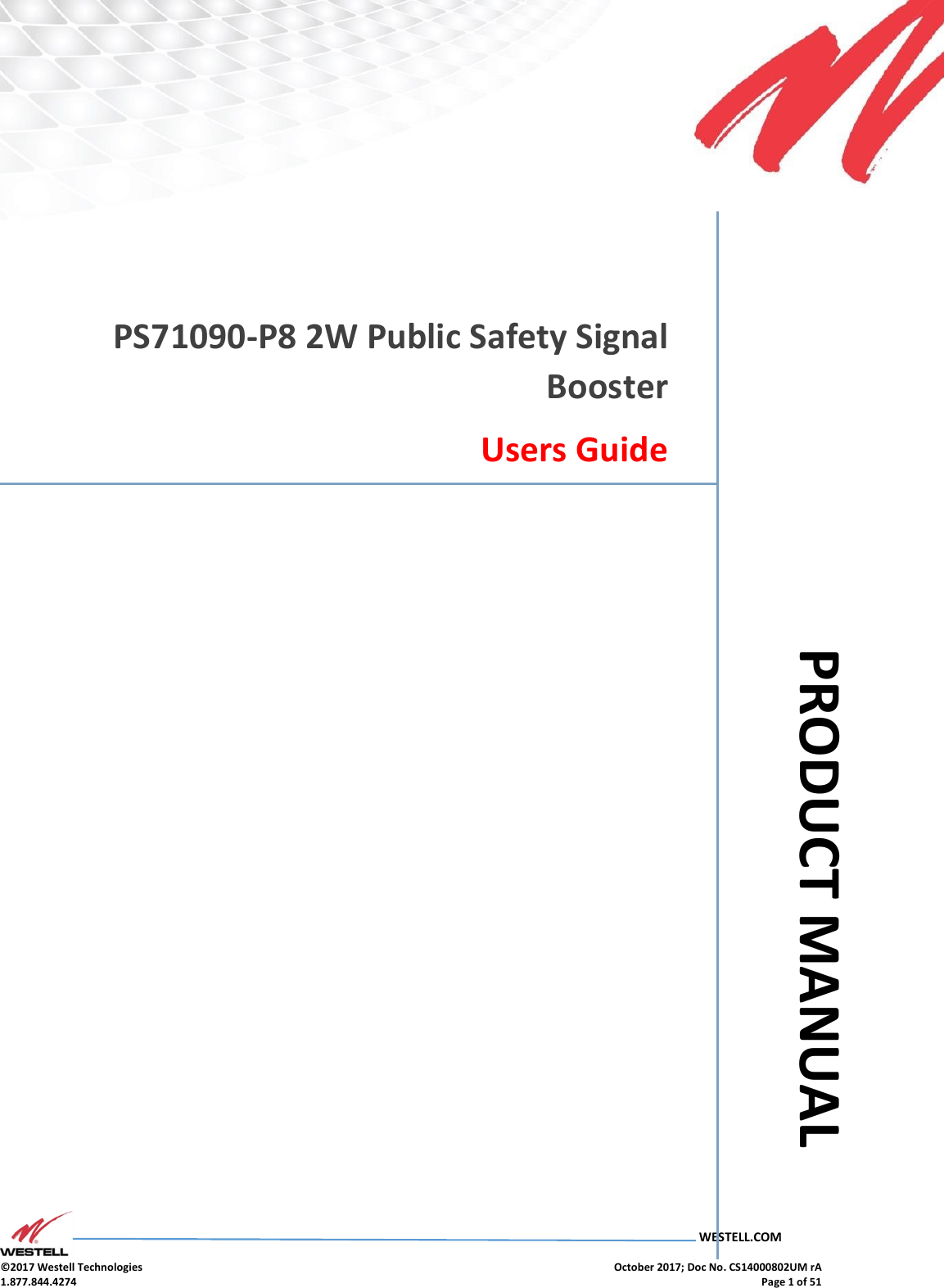
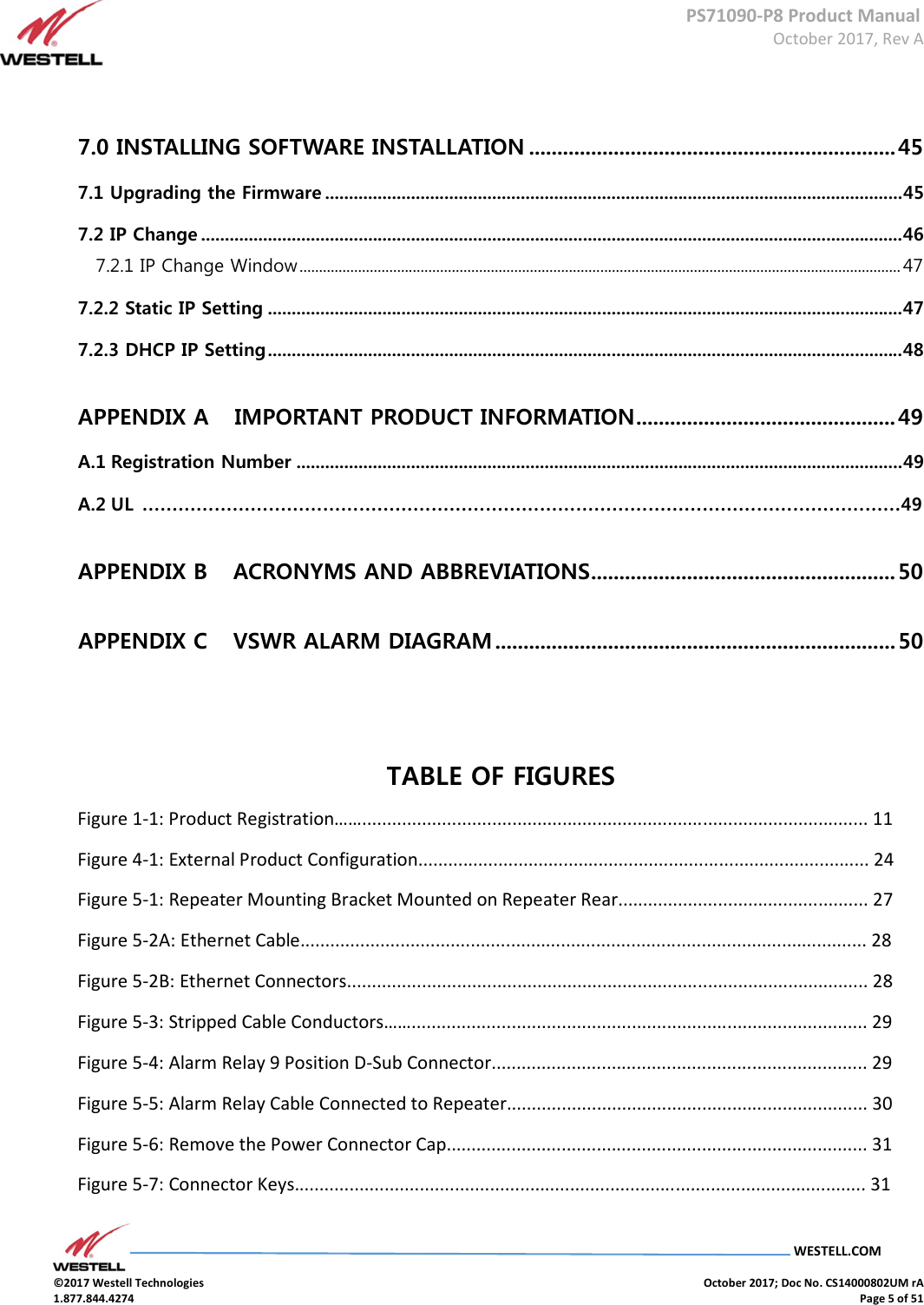
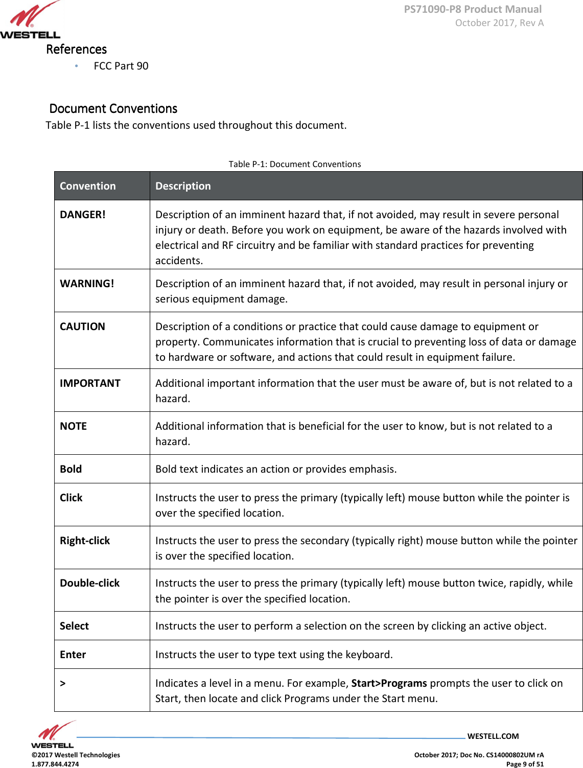
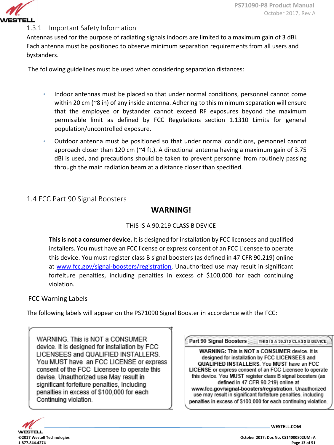
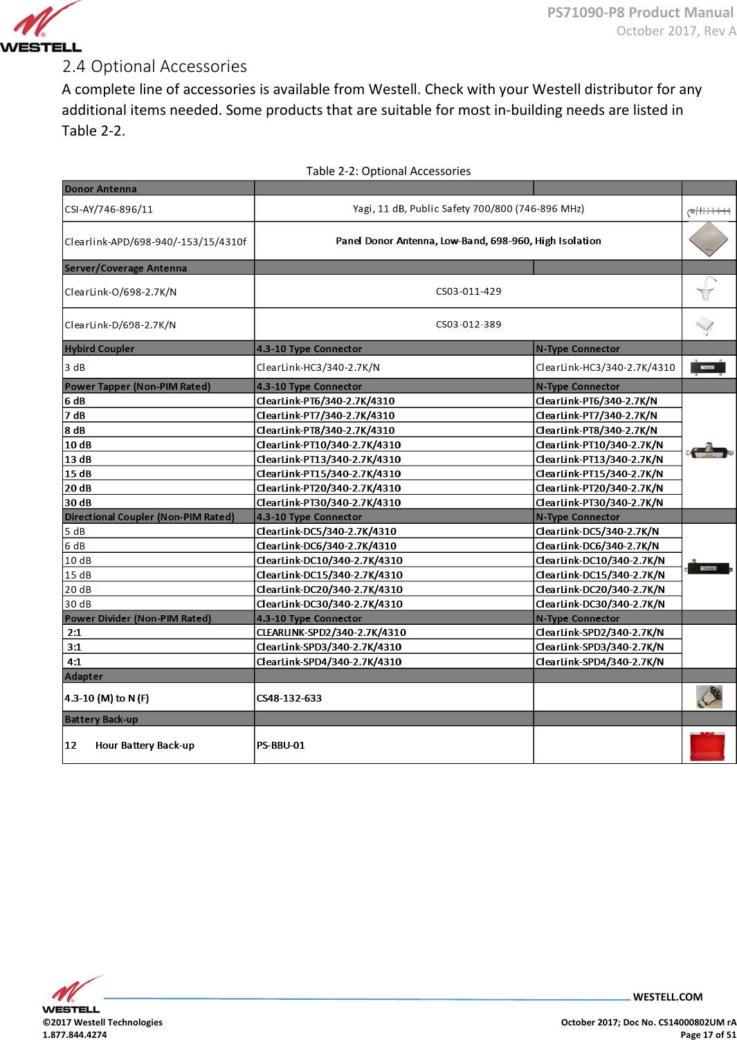
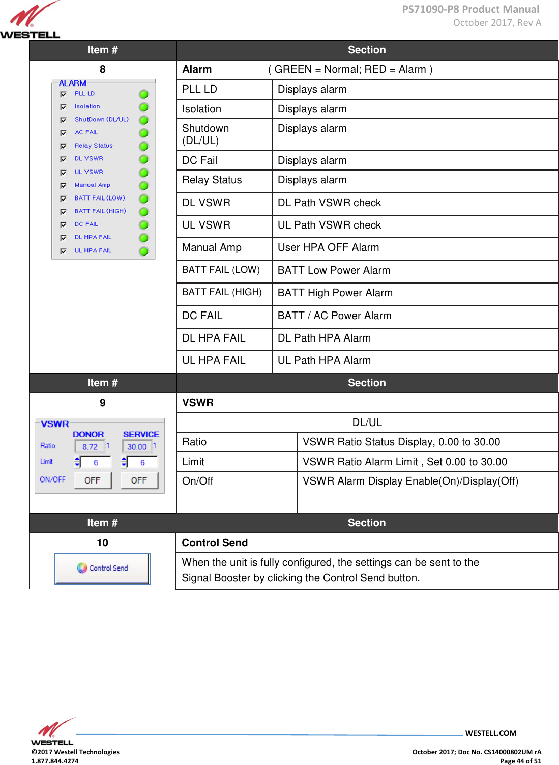
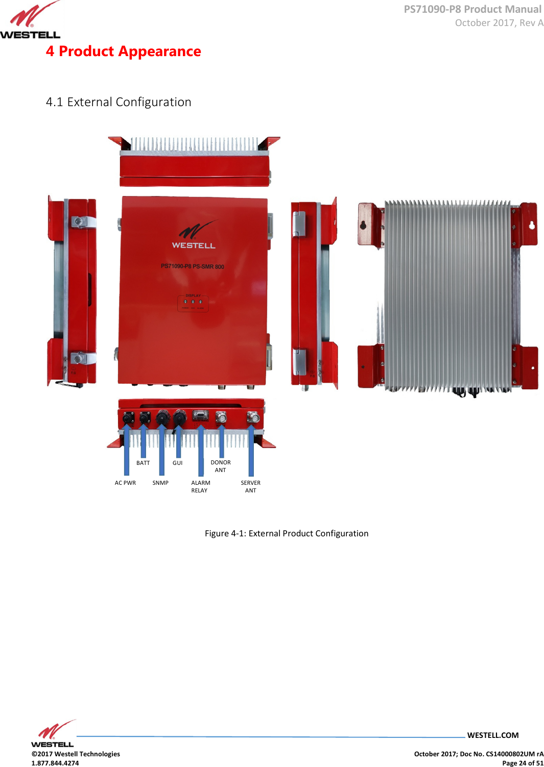
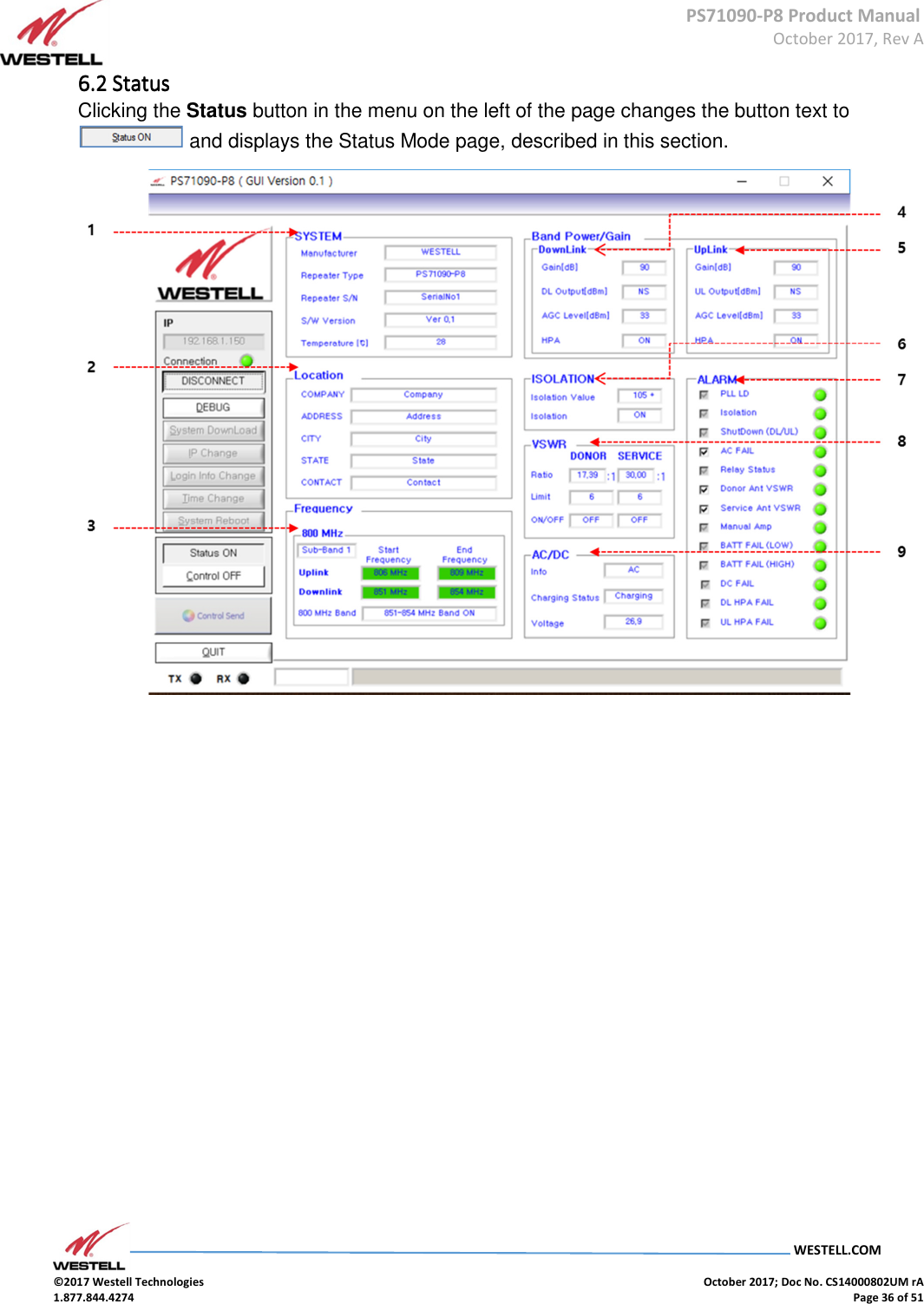
![PS71090-P8 Product Manual October 2017, Rev A WESTELL.COM ©2017 Westell Technologies October 2017; Doc No. CS14000802UM rA 1.877.844.4274 Page 21 of 51 Refer to Section 6 System Operation for more information about the GUI. 3.6 Alarm Status Table 3-6 Alarm Status Mask Item Alarm Enable[ √√√√ ] Disable[ ] Condition/ Troubleshooting AC Power Input DC Power Input Repeater Unit LED GUI Display POWER ISO ALARM AC FAIL [√] Power : AC (Normal) O X Solid OFF OFF ALL GREEN (Normal) DC FAIL [√] BATT FAIL (L) [√] BATT FAIL (H) [√] PLL LD [√] PLL LD (Alarm1 & Alarm2) X O Solid OFF Blinking Relay Status : RED PLL LD : RED DL/UL HPA : RED Manual Amp : RED Rest GREEN Isolation [√] Minimum isolation between Donor & server Antenna = Gain+15dB (Alarm1 & Alarm2) X O Solid Blinking OFF Relay Status : RED Isolation : RED DL/UL HPA : RED Manual Amp : RED Rest GREEN Shutdown (DL/UL) [√] Too strong signal from CELL TOWER. AGC Out of Range. (Alarm2) X O Solid OFF Solid Relay Status : RED Shutdown (DL/UL) : RED DL/UL HPA : RED Manual Amp : RED Rest GREEN AC FAIL [√] DC ONLY DC Voltage : 27V Alarm All Enable (Alarm1) X O Solid OFF OFF Relay Status : RED AC FAIL : RED Rest GREEN DC FAIL [√] BATT FAIL (L) [√] BATT FAIL (H) [√] AC FAIL [ ] DC ONLY DC Voltage : 27V Disable / Mask : AC FAIL (Normal) X O Solid OFF OFF Relay Status : GREEN AC FAIL : RED Rest GREEN DC FAIL [√] BATT FAIL (L) [√] BATT FAIL (H) [√]](https://usermanual.wiki/Westell/PS71090-P8/User-Guide-3663833-Page-21.png)
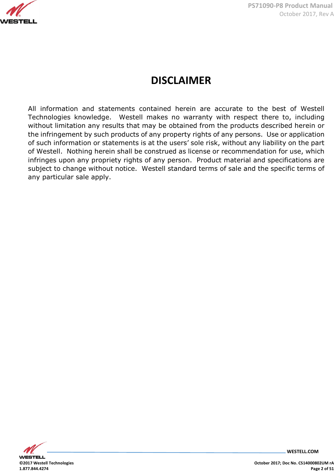
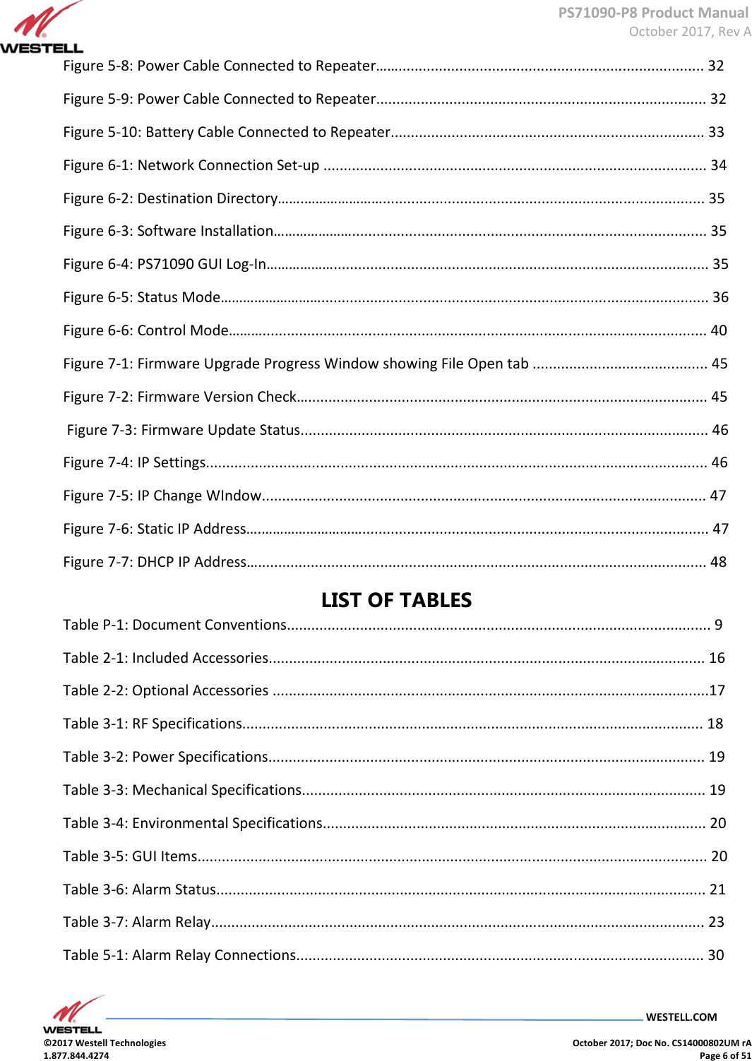
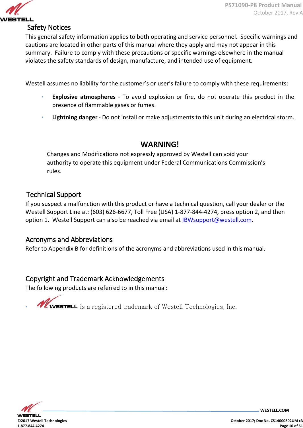
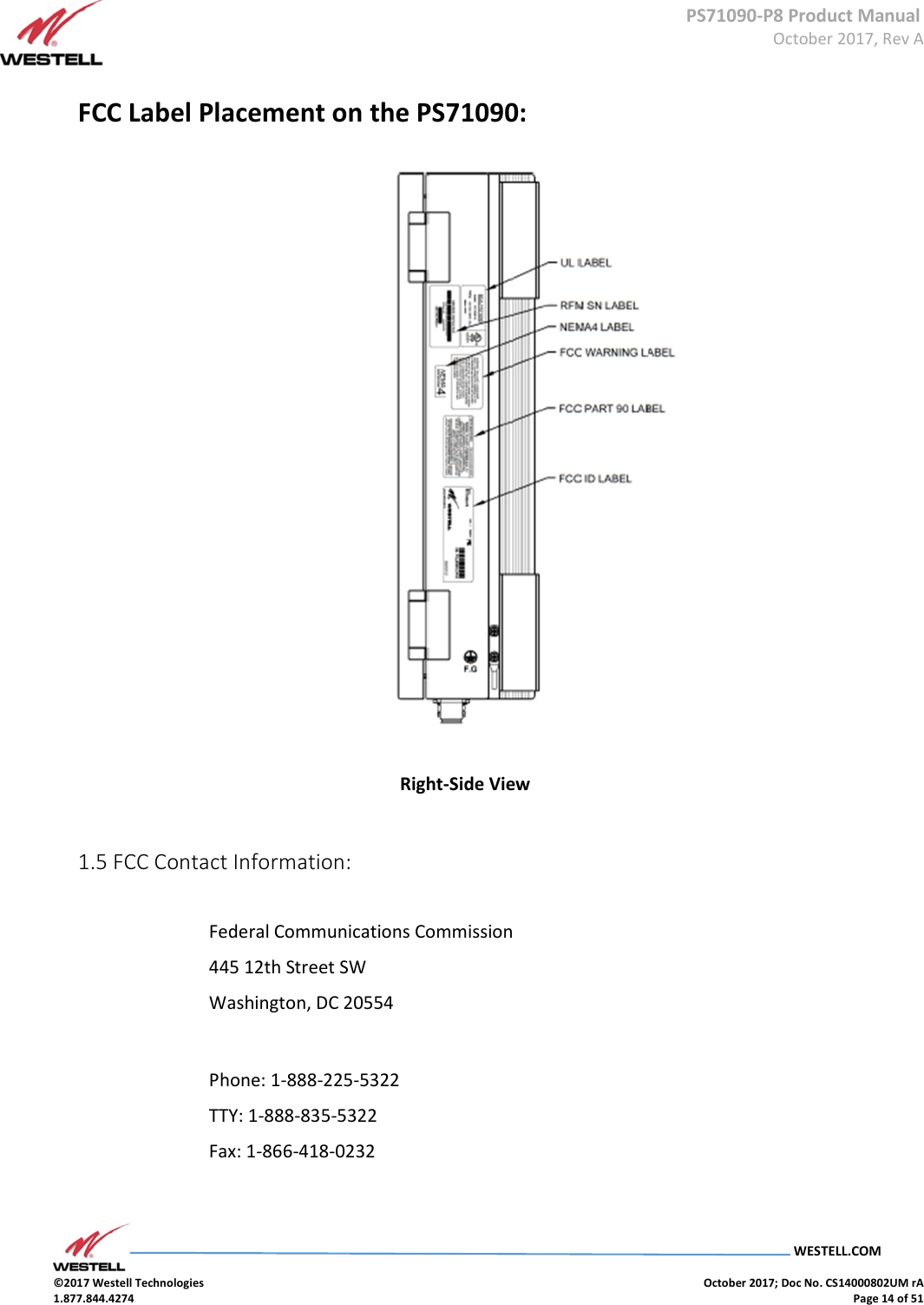
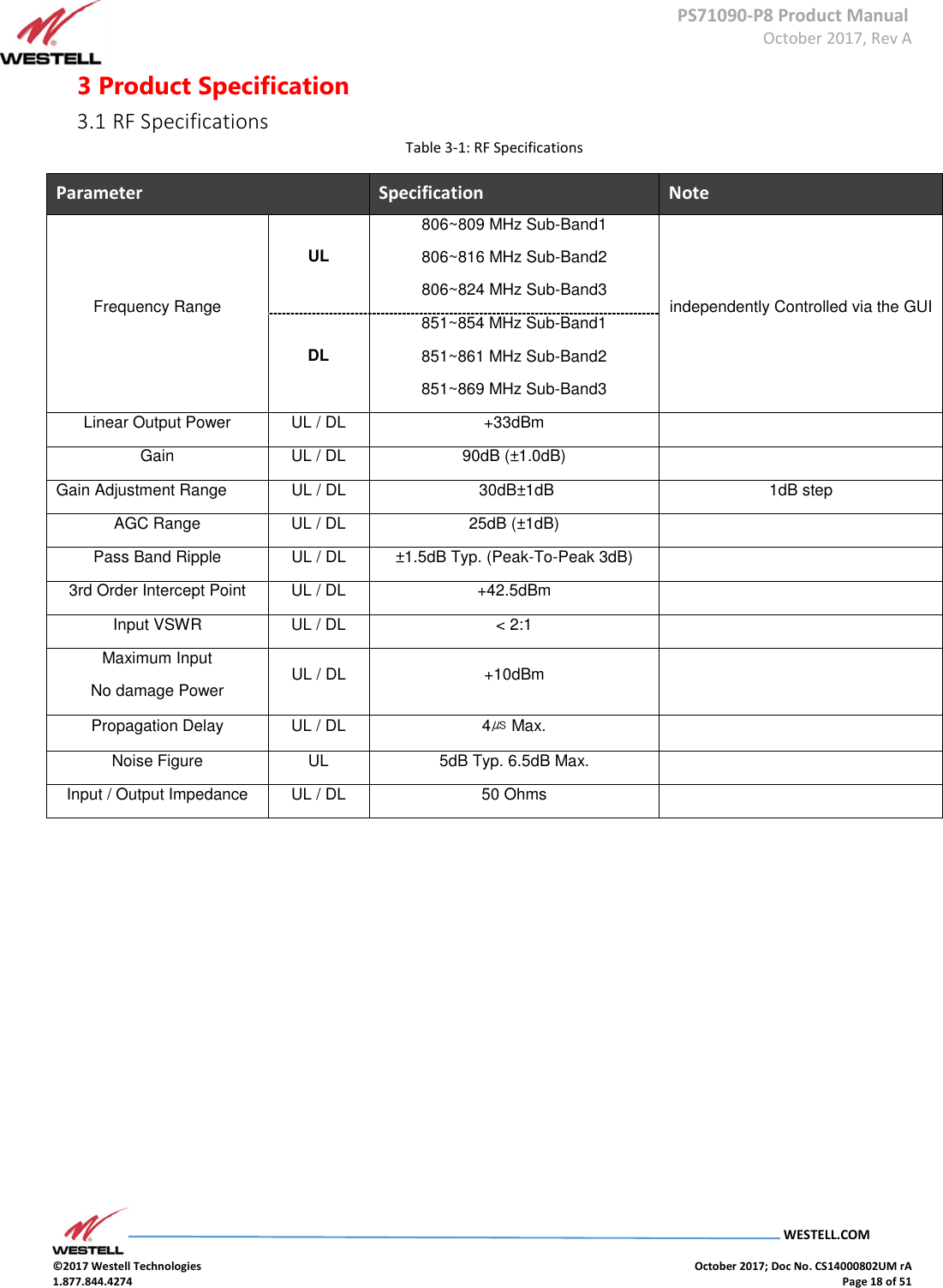
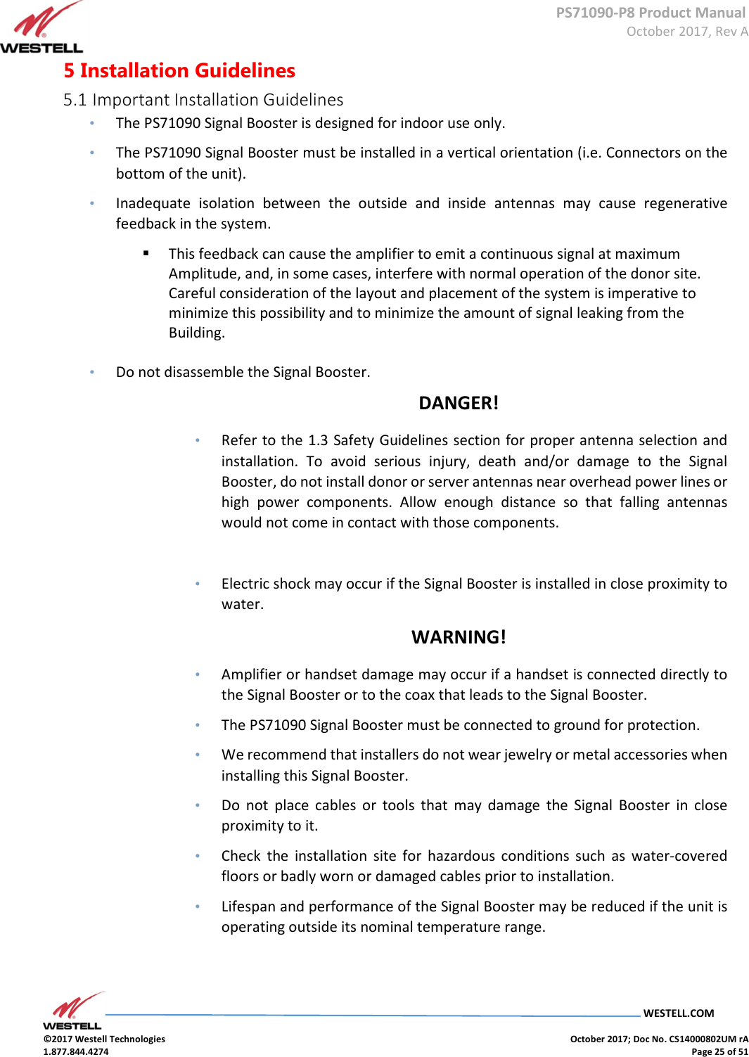
![PS71090-P8 Product Manual October 2017, Rev A WESTELL.COM ©2017 Westell Technologies October 2017; Doc No. CS14000802UM rA 1.877.844.4274 Page 22 of 51 DL VSWR [√] DL VSWR : > set Value (Alarm3) X O Solid OFF Solid Relay Status: RED DL VSWR: RED Rest GREEN [ ] Disable Alarm (Normal) Solid OFF OFF Relay Status: GREEN DL VSWR: RED Rest GREEN UL VSWR [√] UL VSWR : > set Value (Alarm3) X O Solid OFF Solid Relay Status: RED UL VSWR: RED Rest GREEN [ ] Disable Alarm (Normal) Solid OFF OFF Relay Status: GREEN UL VSWR: RED Rest GREEN Manual Amp [√] Manual Amp (Alarm2) X O Solid OFF Solid Relay Status: RED Manual Amp: RED DL/UL HPA Fail : RED Rest GREEN AC FAIL [ ] Power : DC DC Voltage : <23.2V (+/- 0.3V) Disable Alarm : AC FAIL (Alarm1) X O Blinking OFF OFF Relay Status: RED AC FAIL: RED DC FAIL: RED BATT FAIL (LOW): RED Rest GREEN DC FAIL [√] BATT FAIL (L) [√] BATT FAIL (H) [√] AC FAIL [ ] Power : DC X O Blinking OFF OFF Relay Status: RED AC FAIL: RED DC FAIL: RED BATT FAIL (HIGH): RED Rest GREEN DC FAIL [√] DC Voltage : 28.8V (+/- 0.3V) Disable Alarm : AC FAIL (Alarm1) BATT FAIL (L) [√] BATT FAIL (H) [√]](https://usermanual.wiki/Westell/PS71090-P8/User-Guide-3663833-Page-22.png)
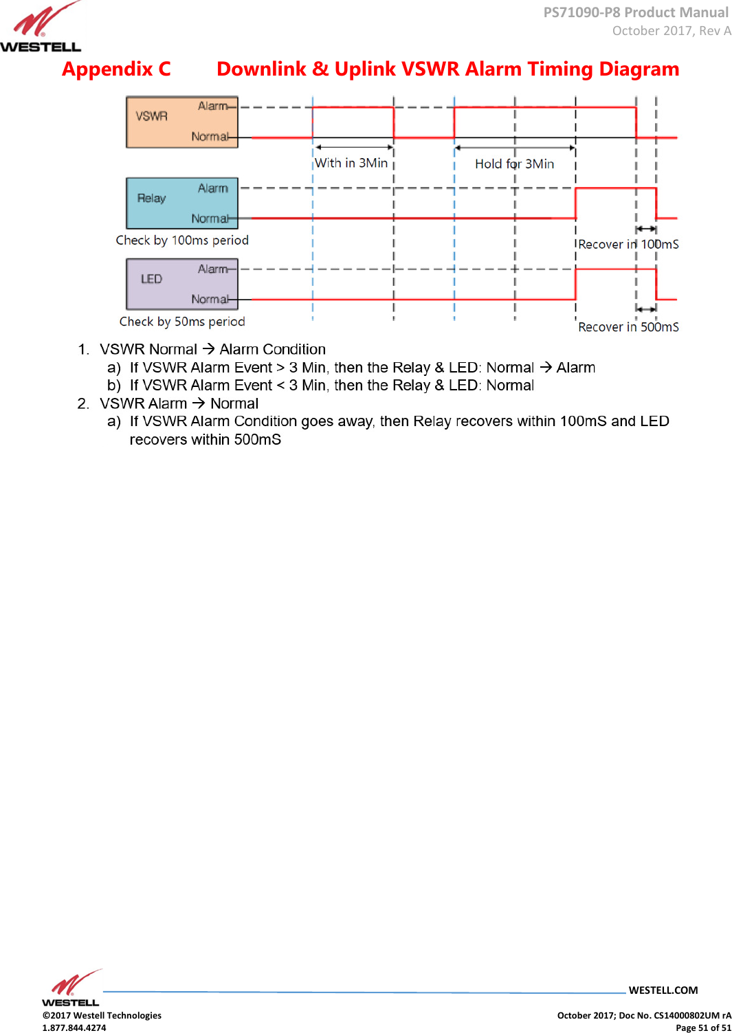
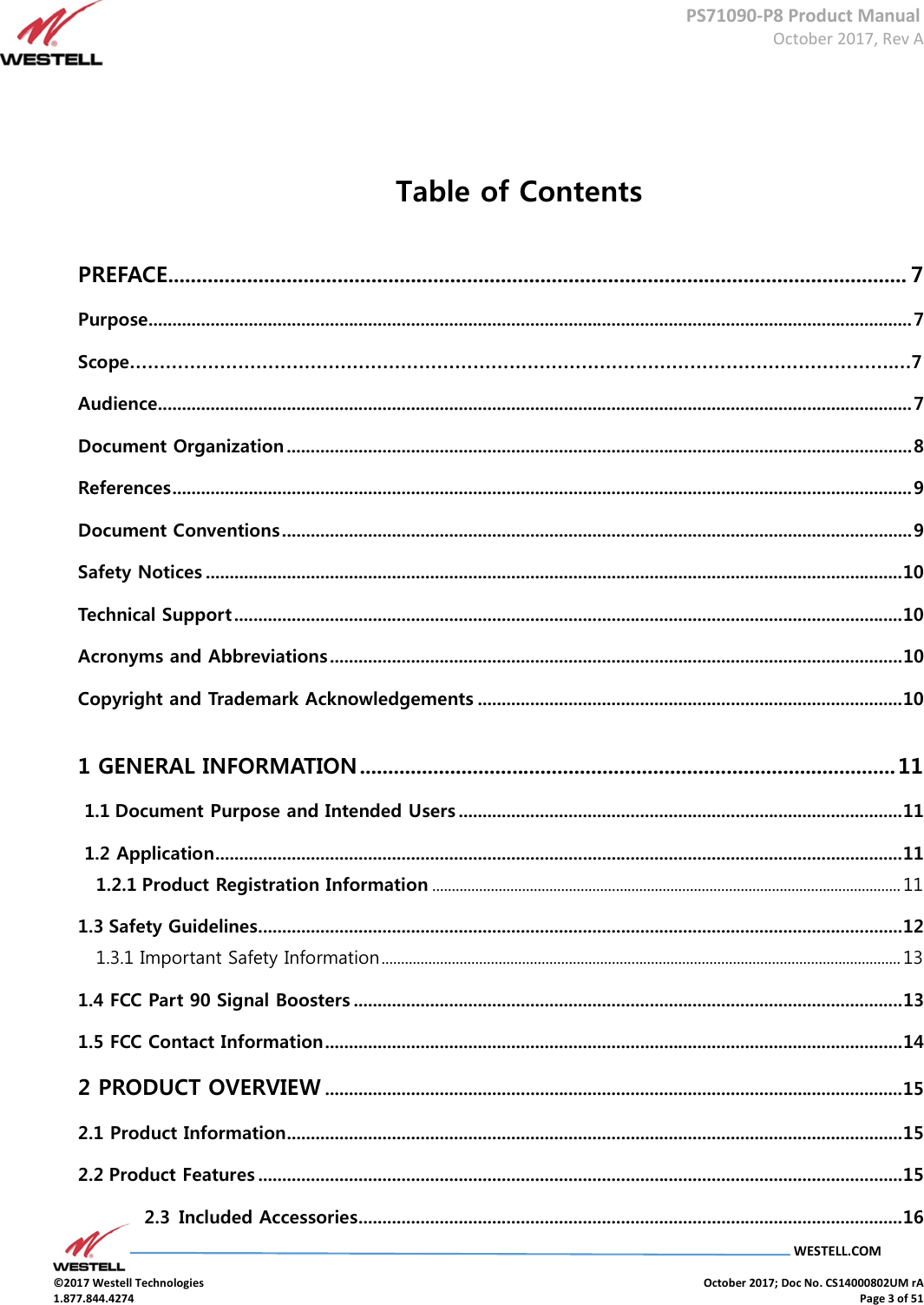
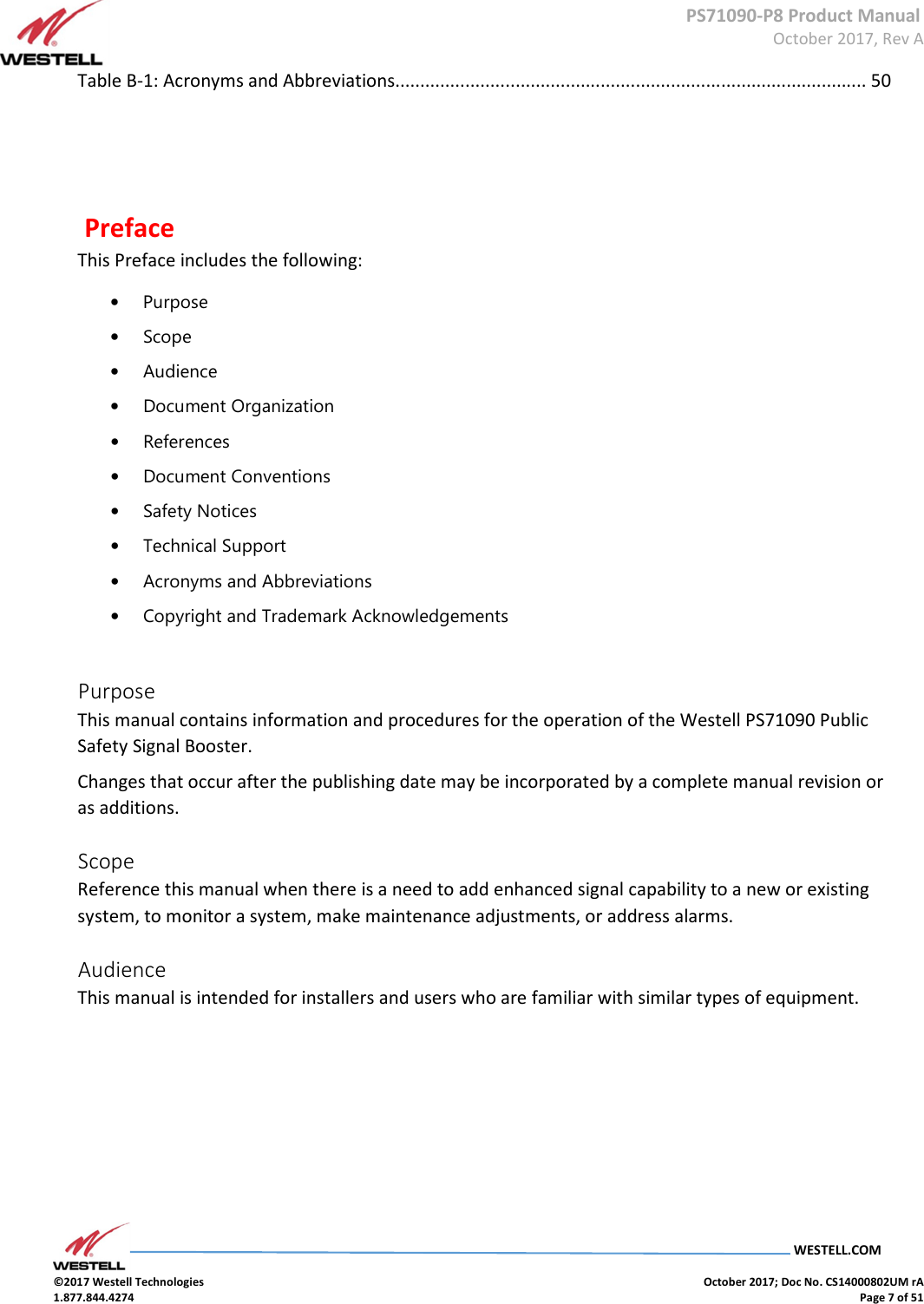
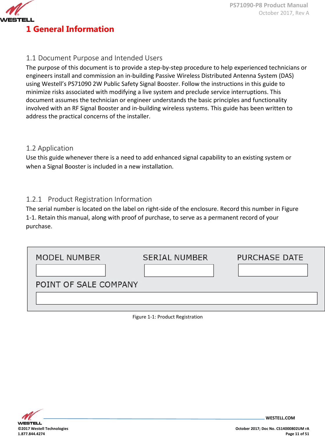
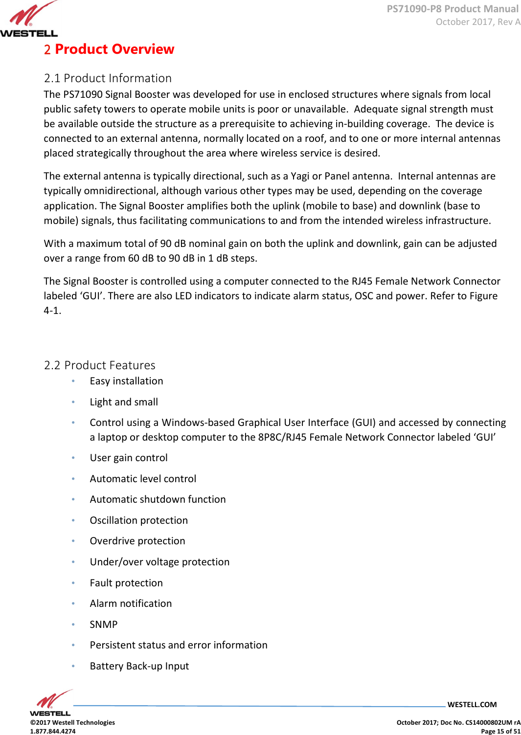
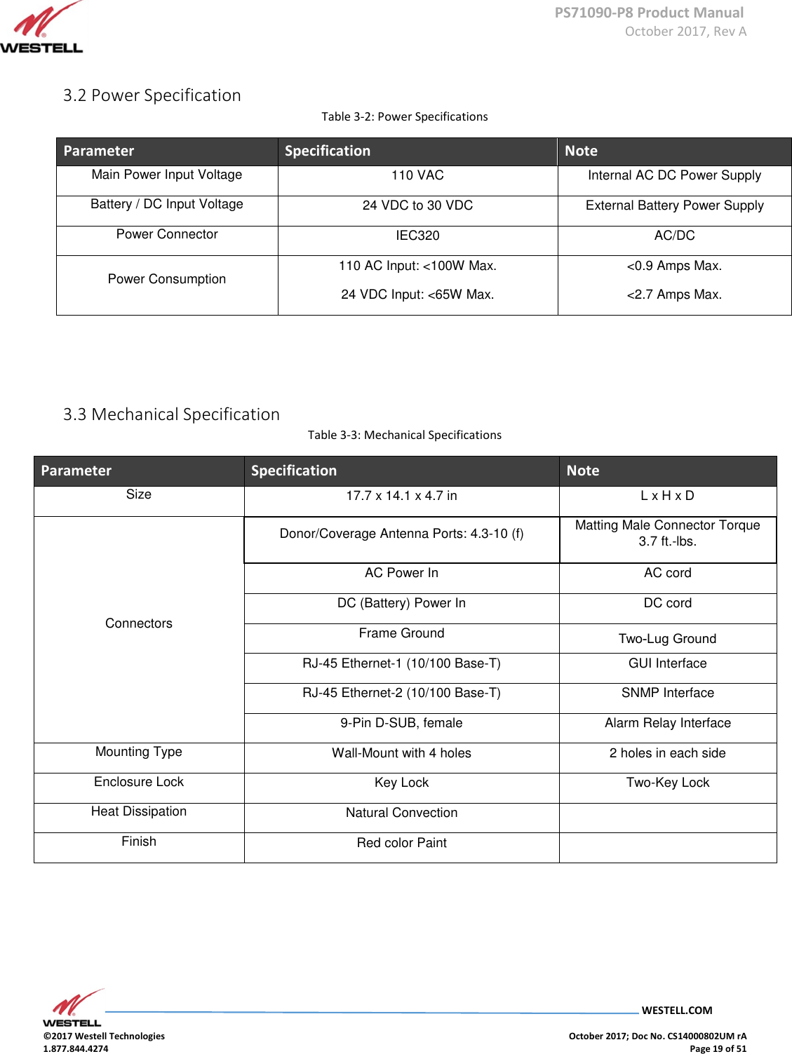
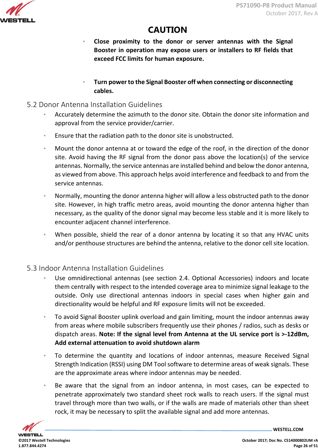
![PS71090-P8 Product Manual October 2017, Rev A WESTELL.COM ©2017 Westell Technologies October 2017; Doc No. CS14000802UM rA 1.877.844.4274 Page 23 of 51 DL HPA FAIL [√] DL HPA FAIL (Alarm2) X O Solid OFF Solid Relay Status: RED Manual Amp: RED DL HPA FAIL: RED Rest: GREEN UL HPA FAIL [√] UL HPA FAIL (Alarm2) X O Solid OFF Solid Relay Status: RED Manual Amp: RED UL HPA FAIL: RED Rest: GREEN DC OVER CURRENT (UL) [√] UL Input power too Strong (Alarm2) X O Solid OFF Solid Relay Status: RED Manual Amp: RED UL HPA FAIL: RED Rest: GREEN 3.7 Alarm Relay Table 3-7 Alarm Relay Shutdown Signal Relay Status Note Normally Open NO (pin 2) + CC (pin 3) PIN 1 NC, PIN 2 NO, PIN 3 CC PIN 4 NC, PIN 5 NO, PIN 6 CC PIN 7 NC, PIN 8 NO, PIN 9 CC Normally Closed NC (pin 1) + CC (pin 3) NOTE Either method in Table 3-7 would trigger the following alarms: Antenna Malfunction, PA Failure and Power Failure. ALARM 1 : System component failure, and/or loss of power – AC/DC (Pin 1,2,3) ALARM 2 : Active PA System failure / PA system failure (Pin 4,5,6) ALARM 3 : Antenna failure – Donor and Server VSWR Alarm (Pin7,8,9) (See Appendix C for VSWR Alarm Timing Diagram)](https://usermanual.wiki/Westell/PS71090-P8/User-Guide-3663833-Page-23.png)
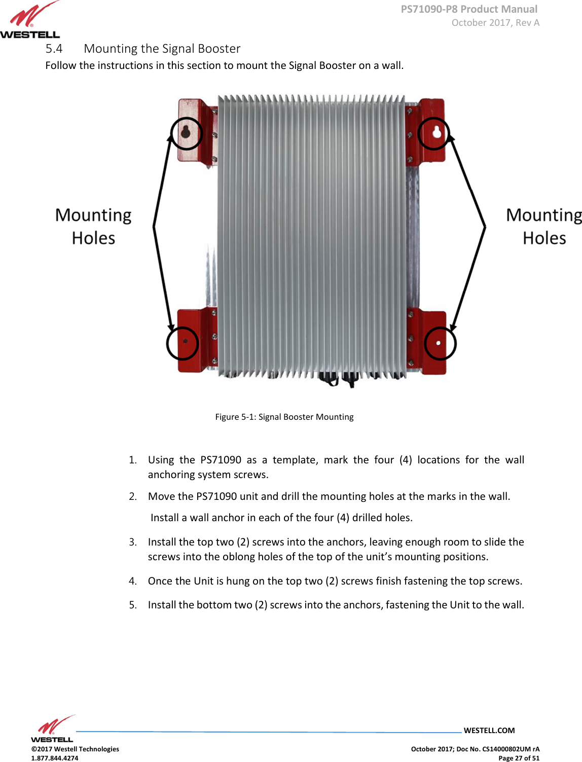
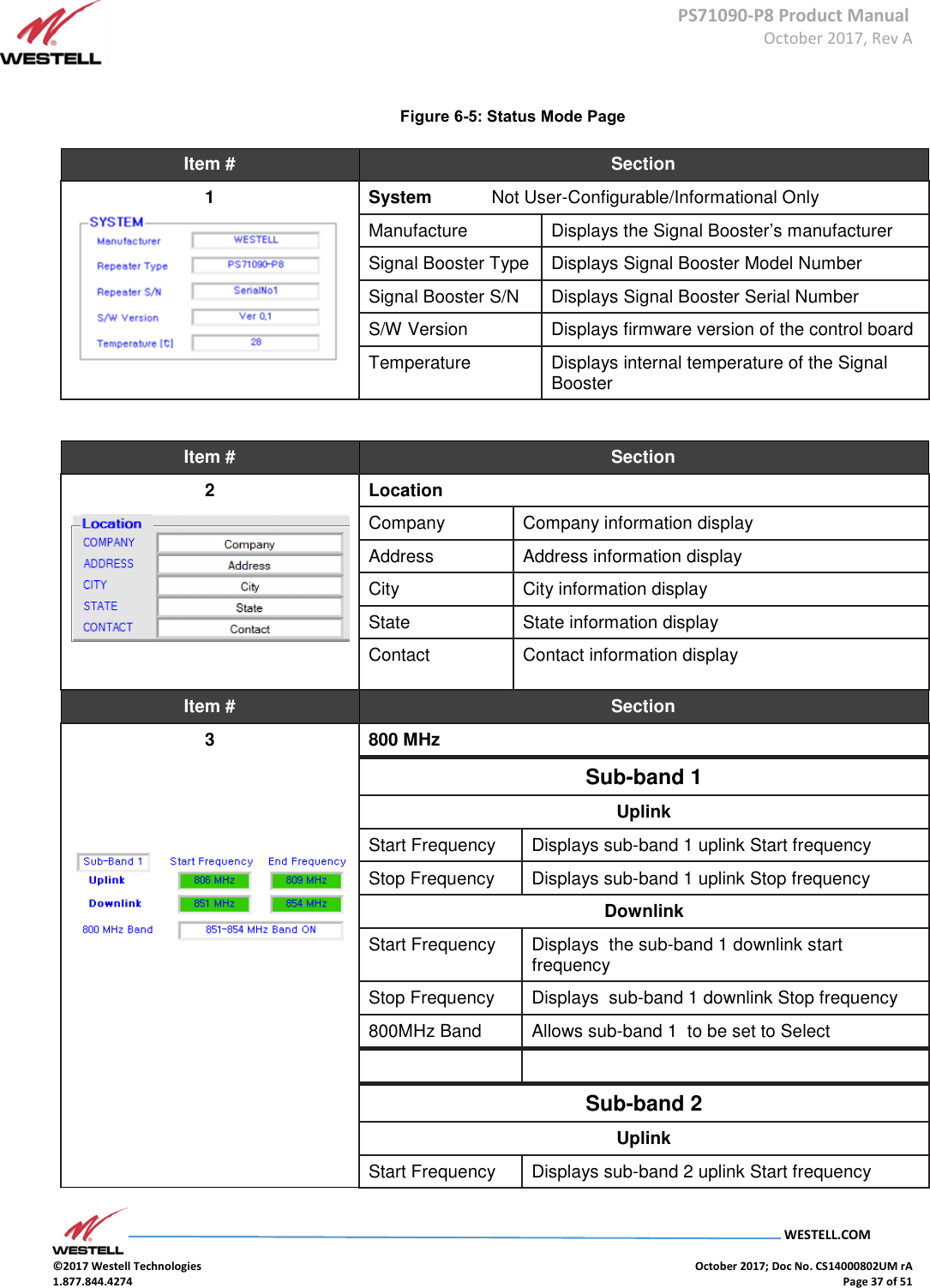
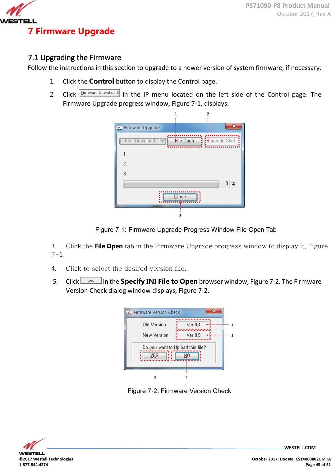
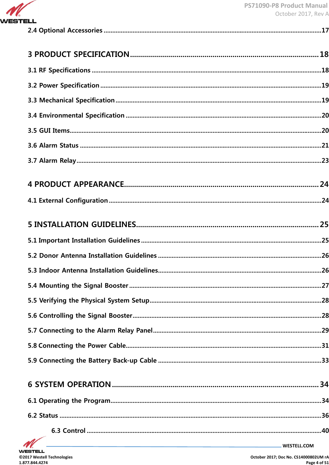
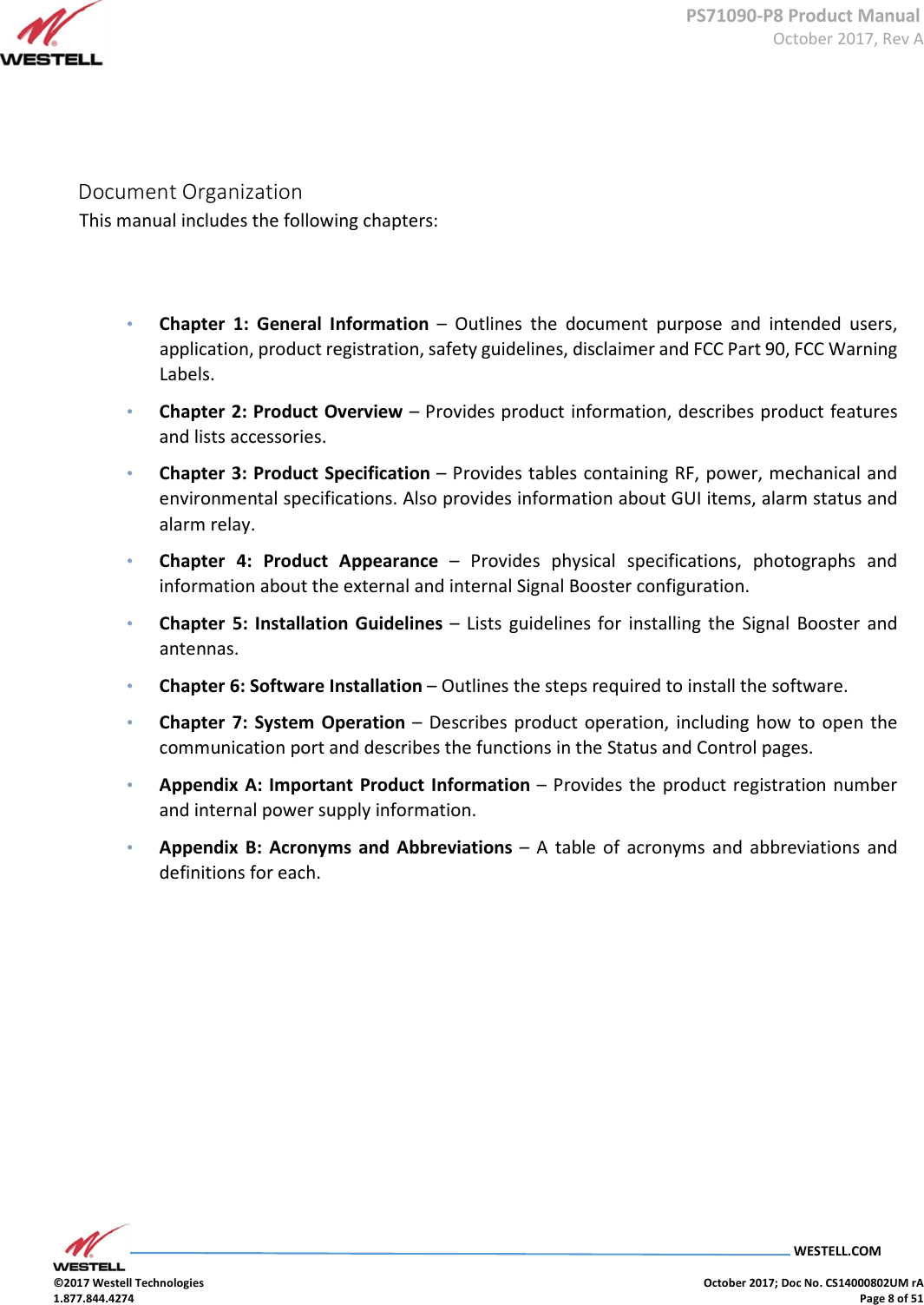
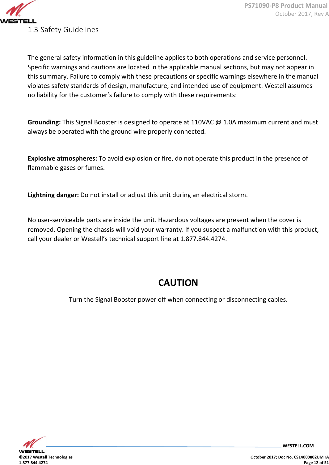
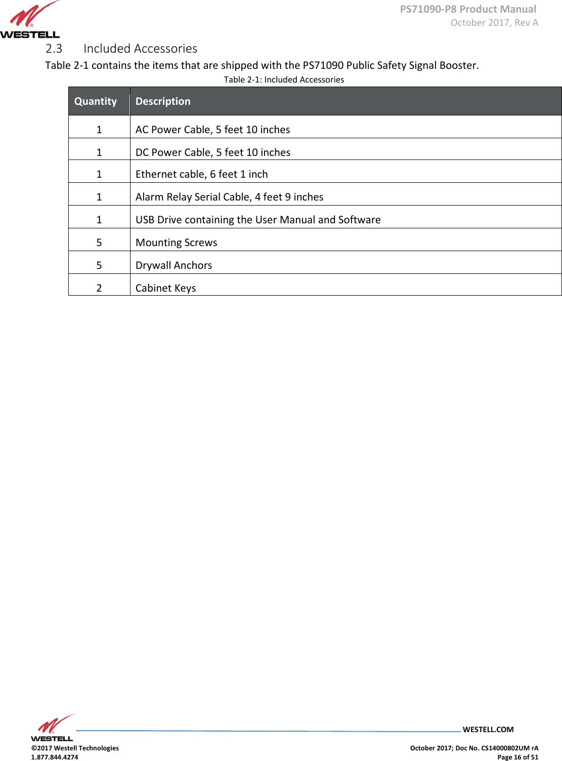
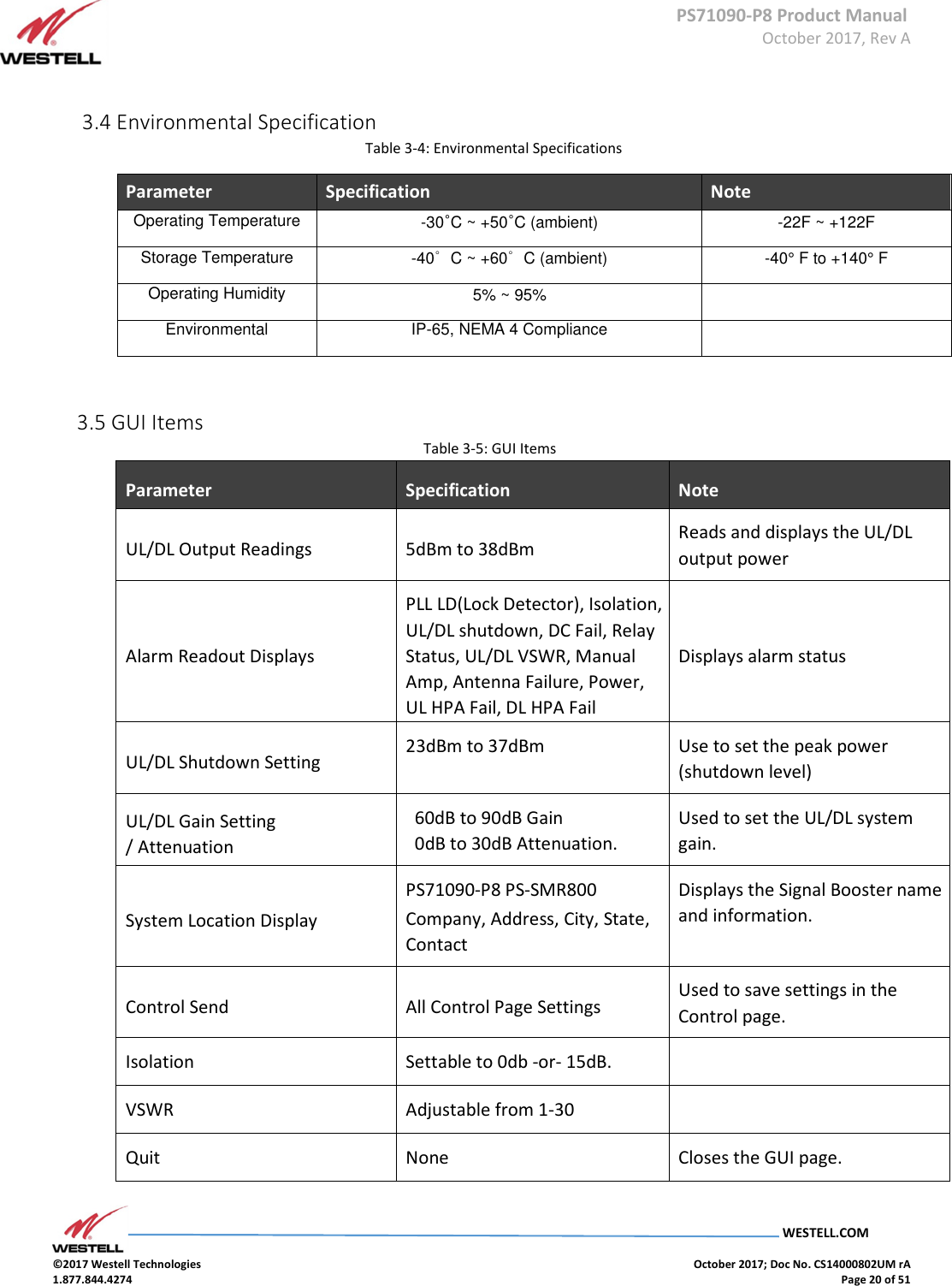
![PS71090-P8 Product Manual October 2017, Rev A WESTELL.COM ©2017 Westell Technologies October 2017; Doc No. CS14000802UM rA 1.877.844.4274 Page 38 of 51 Item # Section Stop Frequency Displays sub-band 2 uplink Stop frequency Downlink Start Frequency Displays sub-band 2 downlink start frequency Stop Frequency Displays sub-band 2 downlink Stop frequency 800MHz Band Allows sub-band 2 to be set to Select Sub-band 3 Uplink Start Frequency Displays sub-band 3 uplink Start frequency Stop Frequency Displays sub-band 3 uplink Stop frequency Downlink Start Frequency Displays sub-band 3 downlink Start frequency Stop Frequency Displays sub-band 3 downlink Stop frequency 800MHz Band Allows sub-band 3 to be set to Select Item # Section 4 Downlink Gain [dB] Displays downlink gain Output (dBm) Displays Output value AGC Level [dBm] Displays Automatic Gain Control Level HPA Displays Down link HPA On/Off Item # Section 5 Uplink Gain (dB) Displays status of the uplink gain UL Output [dBm] Displays uplink output level ALC Level [dBm] Displays Automatic Gain Control Level HPA Displays Up link HPA On/Off](https://usermanual.wiki/Westell/PS71090-P8/User-Guide-3663833-Page-38.png)
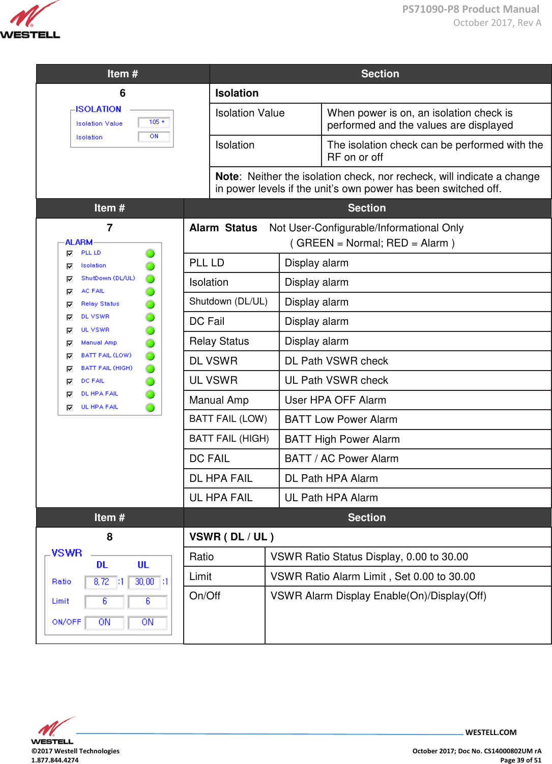
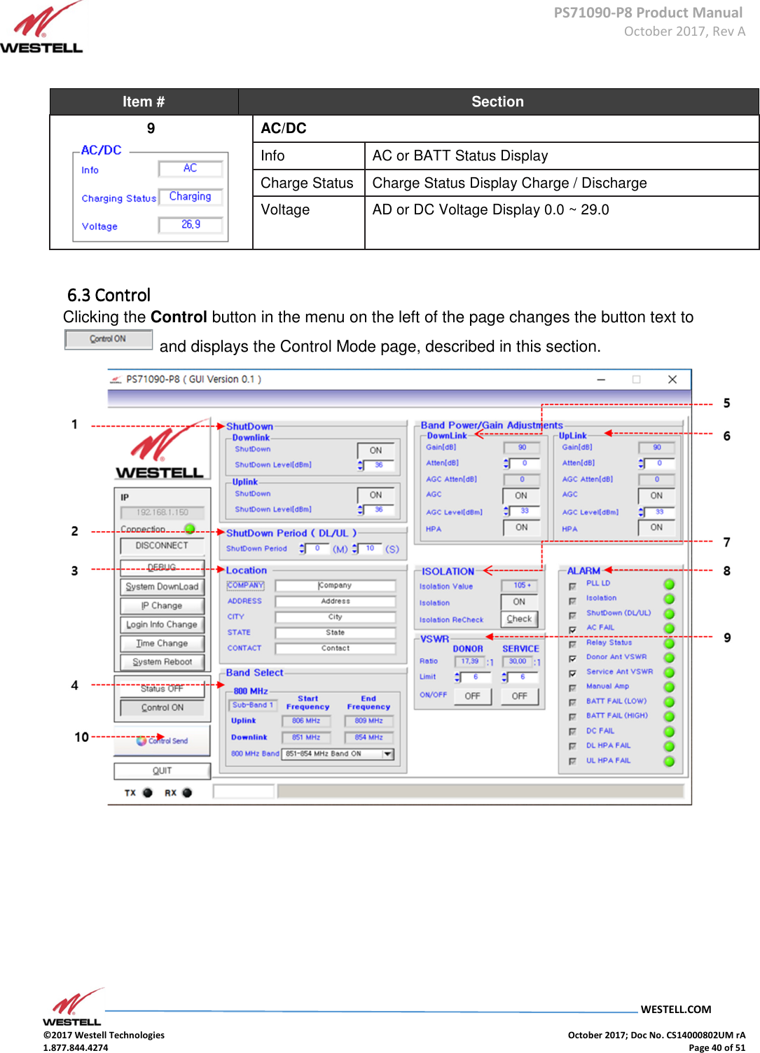
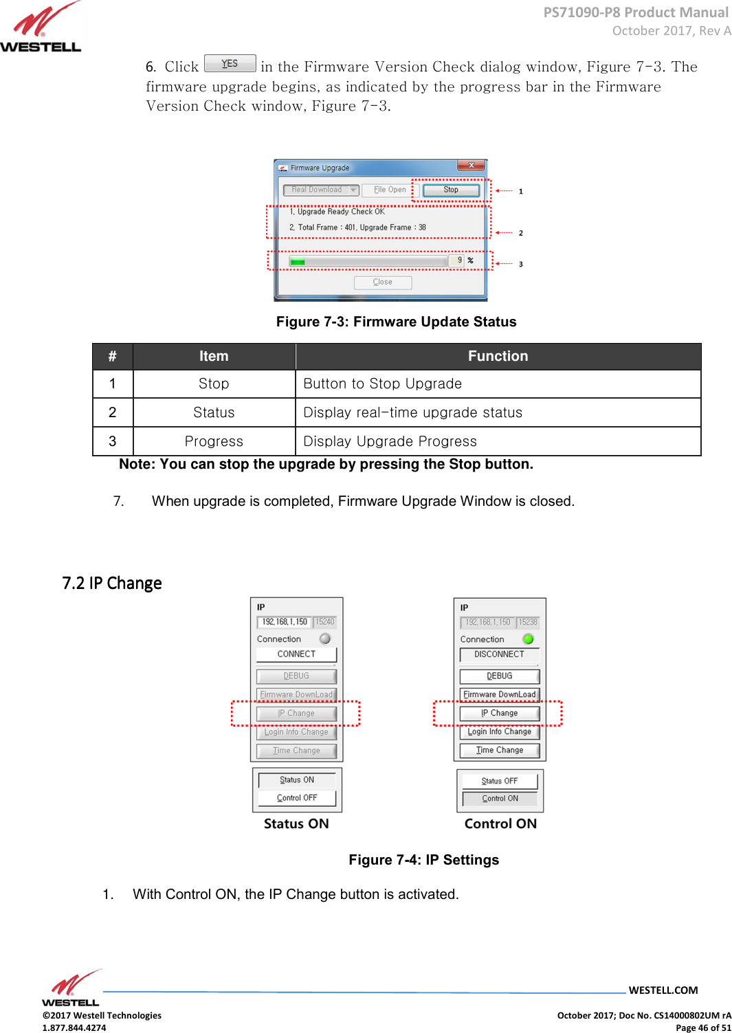
![PS71090-P8 Product Manual October 2017, Rev A WESTELL.COM ©2017 Westell Technologies October 2017; Doc No. CS14000802UM rA 1.877.844.4274 Page 41 of 51 Figure 6-6: Control Mode Page Item # Section 1 Shutdown Allows the shut-down level to be set Downlink Shutdown Allows the downlink shutdown level to be set to on or off. Shutdown Level [dBm] Allows the maximum shutdown level to be set between 23 and 37 Uplink Shutdown Allows the uplink shut down level to be set to on or off Shutdown Level [dBm] Allows the maximum shutdown level to be set between 23 and 37 Item # Section 2 Shutdown Period Allows the shutdown period to be set Shutdown Period Allows the shutdown period to be set in minutes and seconds. Item # Section 3 Location Company Company information display Address Address information display City City information display State State information display Contact Contact information display](https://usermanual.wiki/Westell/PS71090-P8/User-Guide-3663833-Page-41.png)
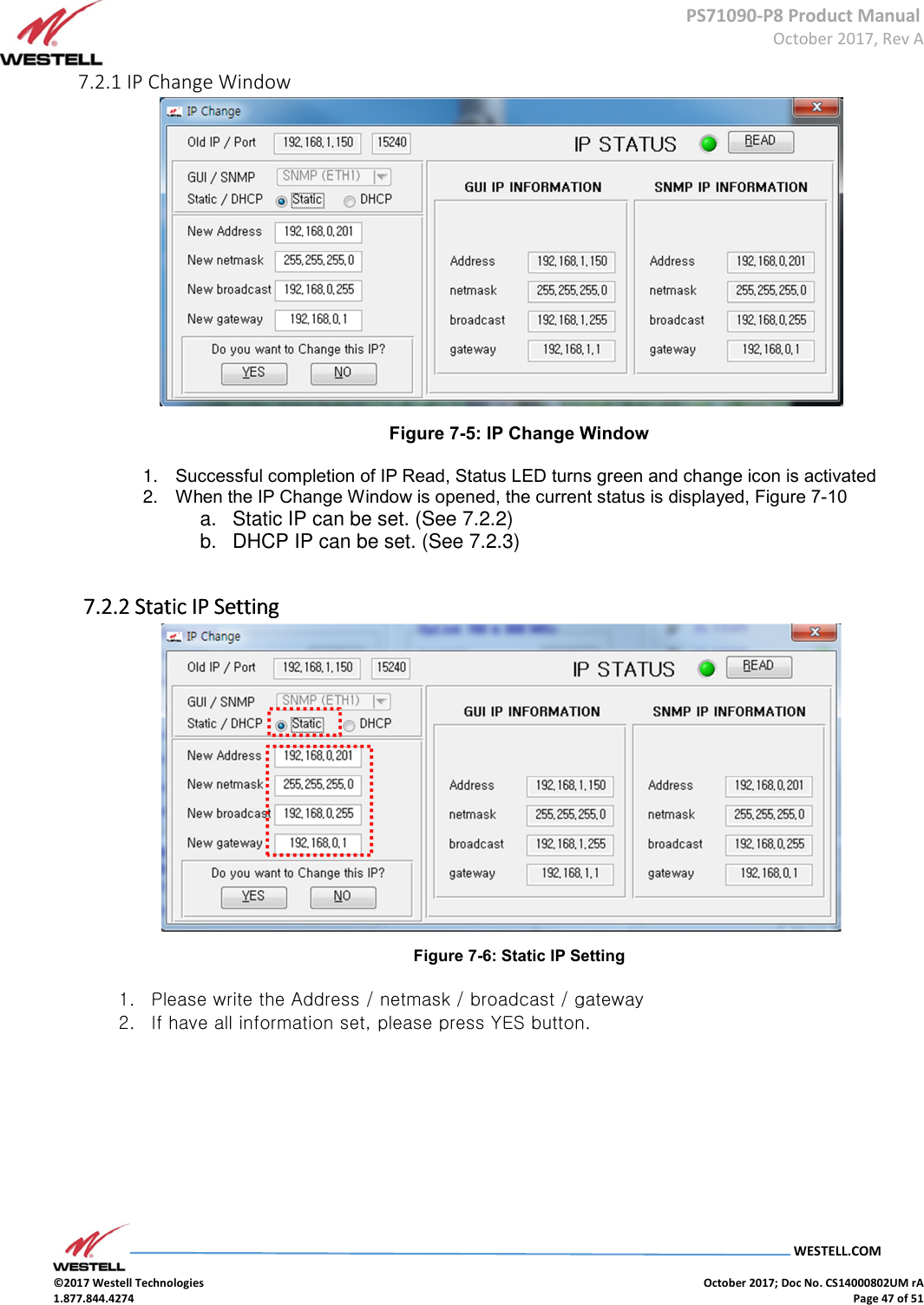
![PS71090-P8 Product Manual October 2017, Rev A WESTELL.COM ©2017 Westell Technologies October 2017; Doc No. CS14000802UM rA 1.877.844.4274 Page 43 of 51 Item # Section 5 Downlink Gain [dB] Displays downlink gain Atten [dB] Sets attenuation value AGC Atten [dB] Displays attenuation value controlled by AGC AGC Control Auto Level Control Function On/Off AGC Level [dBm] Sets the unit’s maximum ALC output value HPA Down link HPA On/Off Item # Section 6 Gain (dB) Displays status of the uplink gain Atten [dB] Sets the attenuation value AGC Atten [dB] Displays attenuation value controlled by AGC AGC Control Auto Gain Control Function On/Off AGC Level [dBm] Sets the unit’s maximum AGC output value HPA Uplink HPA On/Off Item # Section 7 Isolation Isolation Value When power is on, an isolation check is performed and the values display. Isolation The isolation check can be performed with the RF on or off. Isolation Recheck The isolation check can be performed with the RF on or off. Note: Neither the isolation check nor recheck will indicate a change in power levels if the unit’s own power has been switched off.](https://usermanual.wiki/Westell/PS71090-P8/User-Guide-3663833-Page-43.png)