Westell PS71090-P8 Public Safety Signal Booster User Manual
Westell, Inc. Public Safety Signal Booster
Westell >
User Manual

PS71090-P8 Product Manual
October 2017, Rev A
WESTELL.COM
©2017 Westell Technologies October 2017; Doc No. CS14000802UM rA
1.877.844.4274 Page 1 of 51
5689
PS71090-P8 2W Public Safety Signal
Booster
Users Guide
PRODUCT MANUAL

PS71090-P8 Product Manual
October 2017, Rev A
WESTELL.COM
©2017 Westell Technologies October 2017; Doc No. CS14000802UM rA
1.877.844.4274 Page 2 of 51
DISCLAIMER
All information and statements contained herein are accurate to the best of Westell
Technologies knowledge. Westell makes no warranty with respect there to, including
without limitation any results that may be obtained from the products described herein or
the infringement by such products of any property rights of any persons. Use or application
of such information or statements is at the users’ sole risk, without any liability on the part
of Westell. Nothing herein shall be construed as license or recommendation for use, which
infringes upon any propriety rights of any person. Product material and specifications are
subject to change without notice. Westell standard terms of sale and the specific terms of
any particular sale apply.

PS71090-P8 Product Manual
October 2017, Rev A
WESTELL.COM
©2017 Westell Technologies October 2017; Doc No. CS14000802UM rA
1.877.844.4274 Page 3 of 51
Table of Contents
PREFACE................................................................................................................................... 7
Purpose ................................................................................................................................................................ 7
Scope……………………………………………………………………………………………………………….…7
Audience .............................................................................................................................................................. 7
Document Organization ................................................................................................................................... 8
References ........................................................................................................................................................... 9
Document Conventions .................................................................................................................................... 9
Safety Notices .................................................................................................................................................. 10
Technical Support ............................................................................................................................................ 10
Acronyms and Abbreviations ........................................................................................................................ 10
Copyright and Trademark Acknowledgements ......................................................................................... 10
1 GENERAL INFORMATION ............................................................................................... 11
1.1 Document Purpose and Intended Users ............................................................................................. 11
1.2 Application ................................................................................................................................................ 11
1.2.1 Product Registration Information ........................................................................................................................ 11
1.3 Safety Guidelines ....................................................................................................................................... 12
1.3.1 Important Safety Information ..................................................................................................................................... 13
1.4 FCC Part 90 Signal Boosters ................................................................................................................... 13
1.5 FCC Contact Information ......................................................................................................................... 14
2 PRODUCT OVERVIEW
......................................................................................................................... 15
2.1 Product Information ................................................................................................................................. 15
2.2 Product Features ....................................................................................................................................... 15
2.3
Included Accessories .................................................................................................................. 16

PS71090-P8 Product Manual
October 2017, Rev A
WESTELL.COM
©2017 Westell Technologies October 2017; Doc No. CS14000802UM rA
1.877.844.4274 Page 4 of 51
2.4 Optional Accessories ................................................................................................................................ 17
3 PRODUCT SPECIFICATION .............................................................................................. 18
3.1 RF Specifications ....................................................................................................................................... 18
3.2 Power Specification .................................................................................................................................. 19
3.3 Mechanical Specification ......................................................................................................................... 19
3.4 Environmental Specification ................................................................................................................... 20
3.5 GUI Items .................................................................................................................................................... 20
3.6 Alarm Status .............................................................................................................................................. 21
3.7 Alarm Relay ................................................................................................................................................ 23
4 PRODUCT APPEARANCE................................................................................................. 24
4.1 External Configuration ............................................................................................................................. 24
5 INSTALLATION GUIDELINES ........................................................................................... 25
5.1 Important Installation Guidelines .......................................................................................................... 25
5.2 Donor Antenna Installation Guidelines ................................................................................................ 26
5.3 Indoor Antenna Installation Guidelines ................................................................................................ 26
5.4 Mounting the Signal Booster ................................................................................................................. 27
5.5 Verifying the Physical System Setup ..................................................................................................... 28
5.6 Controlling the Signal Booster ............................................................................................................... 28
5.7 Connecting to the Alarm Relay Panel ................................................................................................... 29
5.8
Connecting the Power Cable................................................................................................................... 31
5.9 Connecting the Battery Back-up Cable ................................................................................................ 33
6 SYSTEM OPERATION ....................................................................................................... 34
6.1 Operating the Program ............................................................................................................................ 34
6.2 Status .......................................................................................................................................................... 36
6.3 Control .......................................................................................................................................... 40

PS71090-P8 Product Manual
October 2017, Rev A
WESTELL.COM
©2017 Westell Technologies October 2017; Doc No. CS14000802UM rA
1.877.844.4274 Page 5 of 51
7.0 INSTALLING SOFTWARE INSTALLATION ................................................................. 45
7.1 Upgrading the Firmware ......................................................................................................................... 45
7.2 IP Change ................................................................................................................................................... 46
7.2.1 IP Change Window .......................................................................................................................................................... 47
7.2.2 Static IP Setting ..................................................................................................................................... 47
7.2.3 DHCP IP Setting ..................................................................................................................................... 48
APPENDIX A IMPORTANT PRODUCT INFORMATION .............................................. 49
A.1 Registration Number ............................................................................................................................... 49
A.2 UL ………………………………………………………………………………………………………………49
APPENDIX B ACRONYMS AND ABBREVIATIONS ...................................................... 50
APPENDIX C VSWR ALARM DIAGRAM ....................................................................... 50
TABLE OF FIGURES
Figure 1-1: Product Registration……..................................................................................................... 11
Figure 4-1: External Product Configuration.......................................................................................... 24
Figure 5-1: Repeater Mounting Bracket Mounted on Repeater Rear.................................................. 27
Figure 5-2A: Ethernet Cable................................................................................................................. 28
Figure 5-2B: Ethernet Connectors........................................................................................................ 28
Figure 5-3: Stripped Cable Conductors……........................................................................................... 29
Figure 5-4: Alarm Relay 9 Position D-Sub Connector........................................................................... 29
Figure 5-5: Alarm Relay Cable Connected to Repeater........................................................................ 30
Figure 5-6: Remove the Power Connector Cap.................................................................................... 31
Figure 5-7: Connector Keys.................................................................................................................. 31

PS71090-P8 Product Manual
October 2017, Rev A
WESTELL.COM
©2017 Westell Technologies October 2017; Doc No. CS14000802UM rA
1.877.844.4274 Page 6 of 51
Figure 5-8: Power Cable Connected to Repeater……........................................................................... 32
Figure 5-9: Power Cable Connected to Repeater................................................................................. 32
Figure 5-10: Battery Cable Connected to Repeater............................................................................. 33
Figure 6-1: Network Connection Set-up .............................................................................................. 34
Figure 6-2: Destination Directory…….…………………............................................................................... 35
Figure 6-3: Software Installation…………………....................................................................................... 35
Figure 6-4: PS71090 GUI Log-In………………............................................................................................ 35
Figure 6-5: Status Mode………………………............................................................................................... 36
Figure 6-6: Control Mode………............................................................................................................. 40
Figure 7-1: Firmware Upgrade Progress Window showing File Open tab ........................................... 45
Figure 7-2: Firmware Version Check….................................................................................................. 45
Figure 7-3: Firmware Update Status.................................................................................................... 46
Figure 7-4: IP Settings........................................................................................................................... 46
Figure 7-5: IP Change WIndow............................................................................................................. 47
Figure 7-6: Static IP Address….………………………..................................................................................... 47
Figure 7-7: DHCP IP Address….............................................................................................................. 48
LIST OF TABLES
Table P-1: Document Conventions........................................................................................................ 9
Table 2-1: Included Accessories........................................................................................................... 16
Table 2-2: Optional Accessories ...........................................................................................................17
Table 3-1: RF Specifications................................................................................................................. 18
Table 3-2: Power Specifications........................................................................................................... 19
Table 3-3: Mechanical Specifications................................................................................................... 19
Table 3-4: Environmental Specifications.............................................................................................. 20
Table 3-5: GUI Items............................................................................................................................. 20
Table 3-6: Alarm Status........................................................................................................................ 21
Table 3-7: Alarm Relay......................................................................................................................... 23
Table 5-1: Alarm Relay Connections.................................................................................................... 30

PS71090-P8 Product Manual
October 2017, Rev A
WESTELL.COM
©2017 Westell Technologies October 2017; Doc No. CS14000802UM rA
1.877.844.4274 Page 7 of 51
Table B-1: Acronyms and Abbreviations.............................................................................................. 50
Preface
This Preface includes the following:
• Purpose
• Scope
• Audience
• Document Organization
• References
• Document Conventions
• Safety Notices
• Technical Support
• Acronyms and Abbreviations
• Copyright and Trademark Acknowledgements
Purpose
This manual contains information and procedures for the operation of the Westell PS71090 Public
Safety Signal Booster.
Changes that occur after the publishing date may be incorporated by a complete manual revision or
as additions.
Scope
Reference this manual when there is a need to add enhanced signal capability to a new or existing
system, to monitor a system, make maintenance adjustments, or address alarms.
Audience
This manual is intended for installers and users who are familiar with similar types of equipment.

PS71090-P8 Product Manual
October 2017, Rev A
WESTELL.COM
©2017 Westell Technologies October 2017; Doc No. CS14000802UM rA
1.877.844.4274 Page 8 of 51
Document Organization
This manual includes the following chapters:
•
Chapter 1: General Information – Outlines the document purpose and intended users,
application, product registration, safety guidelines, disclaimer and FCC Part 90, FCC Warning
Labels.
•
Chapter 2: Product Overview – Provides product information, describes product features
and lists accessories.
•
Chapter 3: Product Specification – Provides tables containing RF, power, mechanical and
environmental specifications. Also provides information about GUI items, alarm status and
alarm relay.
•
Chapter 4: Product Appearance – Provides physical specifications, photographs and
information about the external and internal Signal Booster configuration.
•
Chapter 5: Installation Guidelines – Lists guidelines for installing the Signal Booster and
antennas.
•
Chapter 6: Software Installation – Outlines the steps required to install the software.
•
Chapter 7: System Operation – Describes product operation, including how to open the
communication port and describes the functions in the Status and Control pages.
•
Appendix A: Important Product Information – Provides the product registration number
and internal power supply information.
•
Appendix B: Acronyms and Abbreviations – A table of acronyms and abbreviations and
definitions for each.
PS71090-P8 Product Manual
October 2017, Rev A
WESTELL.COM
©2017 Westell Technologies October 2017; Doc No. CS14000802UM rA
1.877.844.4274 Page 9 of 51
References
References References
References
•
FCC Part 90
Document Conventions
Document Conventions Document Conventions
Document Conventions
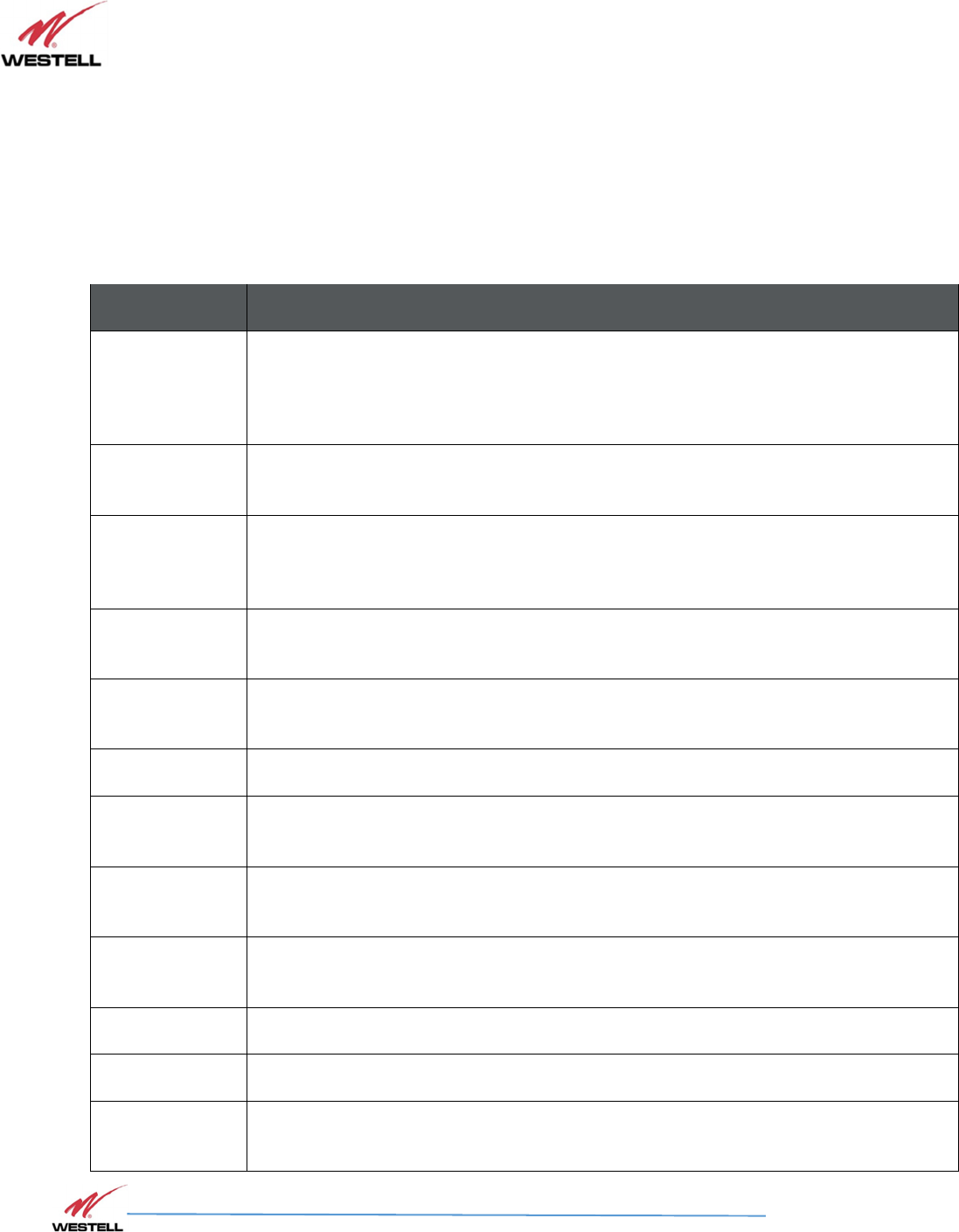
Table P-1 lists the conventions used throughout this document.
Table P-1: Document Conventions
Convention
Descriptio
n
DANGER!
Description of an imminent hazard that, if not avoided, may result in severe personal
injury or death. Before you work on equipment, be aware of the hazards involved with
electrical and RF circuitry and be familiar with standard practices for preventing
accidents.
WARNING!
Description of an imminent hazard that, if not avoided, may result in personal injury or
serious equipment damage.
CAUTION
Description of a conditions or practice that could cause damage to equipment or
property. Communicates information that is crucial to preventing loss of data or damage
to hardware or software, and actions that could result in equipment failure.
IMPORTANT
Additional important information that the user must be aware of, but is not related to a
hazard.
NOTE
Additional information that is beneficial for the user to know, but is not related to a
hazard.
Bold
Bold text indicates an action or provides emphasis.
Click
Instructs the user to press the primary (typically left) mouse button while the
pointer is
over the specified location.
Right
-
click
Instructs the user to press the secondary (typically right) mouse button while the pointer
is over the specified location.
Double
-
click
Instructs the user to press the primary (typically left) mouse
button twice, rapidly, while
the pointer is over the specified location.
Select
Instructs the user to perform a selection on the screen by clicking an active object.
Enter
Instructs the user to type text using the keyboard.
>
Indicates a level in
a menu. For example,
Start>Programs
prompts the user to click on
Start, then locate and click Programs under the Start menu.

PS71090-P8 Product Manual
October 2017, Rev A
WESTELL.COM
©2017 Westell Technologies October 2017; Doc No. CS14000802UM rA
1.877.844.4274 Page 10 of 51
Safety Notices
Safety Notices Safety Notices
Safety Notices
This general safety information applies to both operating and service personnel. Specific warnings and
cautions are located in other parts of this manual where they apply and may not appear in this
summary. Failure to comply with these precautions or specific warnings elsewhere in the manual
violates the safety standards of design, manufacture, and intended use of equipment.
Westell assumes no liability for the customer’s or user’s failure to comply with these requirements:
•
Explosive atmospheres - To avoid explosion or fire, do not operate this product in the
presence of flammable gases or fumes.
•
Lightning danger - Do not install or make adjustments to this unit during an electrical storm.
WARNING!
Changes and Modifications not expressly approved by Westell can void your
authority to operate this equipment under Federal Communications Commission’s
rules.
Technical Support
Technical SupportTechnical Support
Technical Support
If you suspect a malfunction with this product or have a technical question, call your dealer or the
Westell Support Line at: (603) 626-6677, Toll Free (USA) 1-877-844-4274, press option 2, and then
option 1. Westell Support can also be reached via email at IBWsupport@westell.com.
Acronyms and Abbreviations
Acronyms and Abbreviations Acronyms and Abbreviations
Acronyms and Abbreviations
Refer to Appendix B for definitions of the acronyms and abbreviations used in this manual.
Copyright and Trademark Acknowledgements
Copyright and Trademark Acknowledgements Copyright and Trademark Acknowledgements
Copyright and Trademark Acknowledgements
The following products are referred to in this manual:
• is a registered trademark of Westell Technologies, Inc.
PS71090-P8 Product Manual
October 2017, Rev A
WESTELL.COM
©2017 Westell Technologies October 2017; Doc No. CS14000802UM rA
1.877.844.4274 Page 11 of 51
1 General Information
1.1 Document Purpose and Intended Users
The purpose of this document is to provide a step-by-step procedure to help experienced technicians or
engineers install and commission an in-building Passive Wireless Distributed Antenna System (DAS)
using Westell’s PS71090 2W Public Safety Signal Booster. Follow the instructions in this guide to
minimize risks associated with modifying a live system and preclude service interruptions. This
document assumes the technician or engineer understands the basic principles and functionality
involved with an RF Signal Booster and in-building wireless systems. This guide has been written to
address the practical concerns of the installer.
1.2 Application
Use this guide whenever there is a need to add enhanced signal capability to an existing system or
when a Signal Booster is included in a new installation.
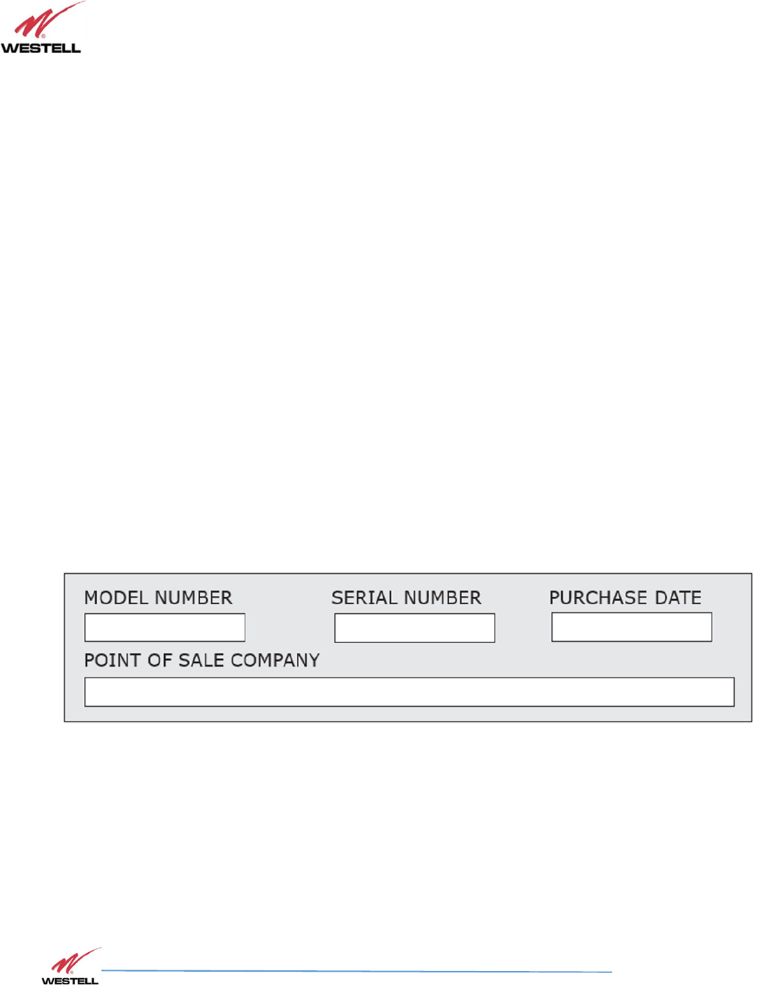
1.2.1 Product Registration Information
The serial number is located on the label on right-side of the enclosure. Record this number in Figure
1-1. Retain this manual, along with proof of purchase, to serve as a permanent record of your
purchase.
Figure 1-1: Product Registration

PS71090-P8 Product Manual
October 2017, Rev A
WESTELL.COM
©2017 Westell Technologies October 2017; Doc No. CS14000802UM rA
1.877.844.4274 Page 12 of 51
1.3 Safety Guidelines
The general safety information in this guideline applies to both operations and service personnel.
Specific warnings and cautions are located in the applicable manual sections, but may not appear in
this summary. Failure to comply with these precautions or specific warnings elsewhere in the manual
violates safety standards of design, manufacture, and intended use of equipment. Westell assumes
no liability for the customer’s failure to comply with these requirements:
Grounding: This Signal Booster is designed to operate at 110VAC @ 1.0A maximum current and must
always be operated with the ground wire properly connected.
Explosive atmospheres: To avoid explosion or fire, do not operate this product in the presence of
flammable gases or fumes.
Lightning danger: Do not install or adjust this unit during an electrical storm.
No user-serviceable parts are inside the unit. Hazardous voltages are present when the cover is
removed. Opening the chassis will void your warranty. If you suspect a malfunction with this product,
call your dealer or Westell’s technical support line at 1.877.844.4274.
CAUTION
Turn the Signal Booster power off when connecting or disconnecting cables.
PS71090-P8 Product Manual
October 2017, Rev A
WESTELL.COM
©2017 Westell Technologies October 2017; Doc No. CS14000802UM rA
1.877.844.4274 Page 13 of 51
1.3.1 Important Safety Information
Antennas used for the purpose of radiating signals indoors are limited to a maximum gain of 3 dBi.
Each antenna must be positioned to observe minimum separation requirements from all users and
bystanders.
The following guidelines must be used when considering separation distances:
•
Indoor antennas must be placed so that under normal conditions, personnel cannot come
within 20 cm (~8 in) of any inside antenna. Adhering to this minimum separation will ensure
that the employee or bystander cannot exceed RF exposures beyond the maximum
permissible limit as defined by FCC Regulations section 1.1310 Limits for general
population/uncontrolled exposure.
•
Outdoor antenna must be positioned so that under normal conditions, personnel cannot
approach closer than 120 cm (~4 ft.). A directional antenna having a maximum gain of 3.75
dBi is used, and precautions should be taken to prevent personnel from routinely passing
through the main radiation beam at a distance closer than specified.
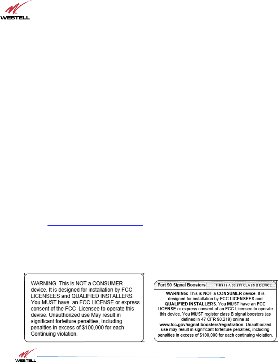
1.4 FCC Part 90 Signal Boosters
WARNING!
THIS IS A 90.219 CLASS B DEVICE
This is not a consumer device. It is designed for installation by FCC licensees and qualified
installers. You must have an FCC license or express consent of an FCC Licensee to operate
this device. You must register class B signal boosters (as defined in 47 CFR 90.219) online
at www.fcc.gov/signal-boosters/registration. Unauthorized use may result in significant
forfeiture penalties, including penalties in excess of $100,000 for each continuing
violation.
FCC Warning Labels
The following labels will appear on the PS71090 Signal Booster in accordance with the FCC:

PS71090-P8 Product Manual
October 2017, Rev A
WESTELL.COM
©2017 Westell Technologies October 2017; Doc No. CS14000802UM rA
1.877.844.4274 Page 14 of 51
FCC Label Placement on the PS71090:
Right-Side View
1.5 FCC Contact Information:
Federal Communications Commission
445 12th Street SW
Washington, DC 20554
Phone: 1-888-225-5322
TTY: 1-888-835-5322
Fax: 1-866-418-0232

PS71090-P8 Product Manual
October 2017, Rev A
WESTELL.COM
©2017 Westell Technologies October 2017; Doc No. CS14000802UM rA
1.877.844.4274 Page 15 of 51
2
22
2 Product Overview
2.1 Product Information
The PS71090 Signal Booster was developed for use in enclosed structures where signals from local
public safety towers to operate mobile units is poor or unavailable. Adequate signal strength must
be available outside the structure as a prerequisite to achieving in-building coverage. The device is
connected to an external antenna, normally located on a roof, and to one or more internal antennas
placed strategically throughout the area where wireless service is desired.
The external antenna is typically directional, such as a Yagi or Panel antenna. Internal antennas are
typically omnidirectional, although various other types may be used, depending on the coverage
application. The Signal Booster amplifies both the uplink (mobile to base) and downlink (base to
mobile) signals, thus facilitating communications to and from the intended wireless infrastructure.
With a maximum total of 90 dB nominal gain on both the uplink and downlink, gain can be adjusted
over a range from 60 dB to 90 dB in 1 dB steps.
The Signal Booster is controlled using a computer connected to the RJ45 Female Network Connector
labeled ‘GUI’. There are also LED indicators to indicate alarm status, OSC and power. Refer to Figure
4-1.
2.2 Product Features
•
Easy installation
•
Light and small
•
Control using a Windows-based Graphical User Interface (GUI) and accessed by connecting
a laptop or desktop computer to the 8P8C/RJ45 Female Network Connector labeled ‘GUI’
•
User gain control
•
Automatic level control
•
Automatic shutdown function
•
Oscillation protection
•
Overdrive protection
•
Under/over voltage protection
•
Fault protection
•
Alarm notification
•
SNMP
•
Persistent status and error information
•
Battery Back-up Input
PS71090-P8 Product Manual
October 2017, Rev A
WESTELL.COM
©2017 Westell Technologies October 2017; Doc No. CS14000802UM rA
1.877.844.4274 Page 16 of 51
2.3 Included Accessories
Table 2-1 contains the items that are shipped with the PS71090 Public Safety Signal Booster.
Table 2-1: Included Accessories
Quantity
Description
1
AC Power Cable, 5 feet 10 inches
1
DC Power Cable, 5 feet 10 inches
1
Ethernet cable, 6 feet 1 inch
1
Alarm Relay Serial Cable, 4 feet 9 inches
1
USB Drive containing the User Manual and
Software
5
Mounting Screws
5
Drywall Anchors
2
Cabinet Keys

PS71090-P8 Product Manual
October 2017, Rev A
WESTELL.COM
©2017 Westell Technologies October 2017; Doc No. CS14000802UM rA
1.877.844.4274 Page 17 of 51
2.4 Optional Accessories
A complete line of accessories is available from Westell. Check with your Westell distributor for any
additional items needed. Some products that are suitable for most in-building needs are listed in
Table 2-2.
Table 2-2: Optional Accessories
PS71090-P8 Product Manual
October 2017, Rev A
WESTELL.COM
©2017 Westell Technologies October 2017; Doc No. CS14000802UM rA
1.877.844.4274 Page 18 of 51
3 Product Specification
3.1 RF Specifications
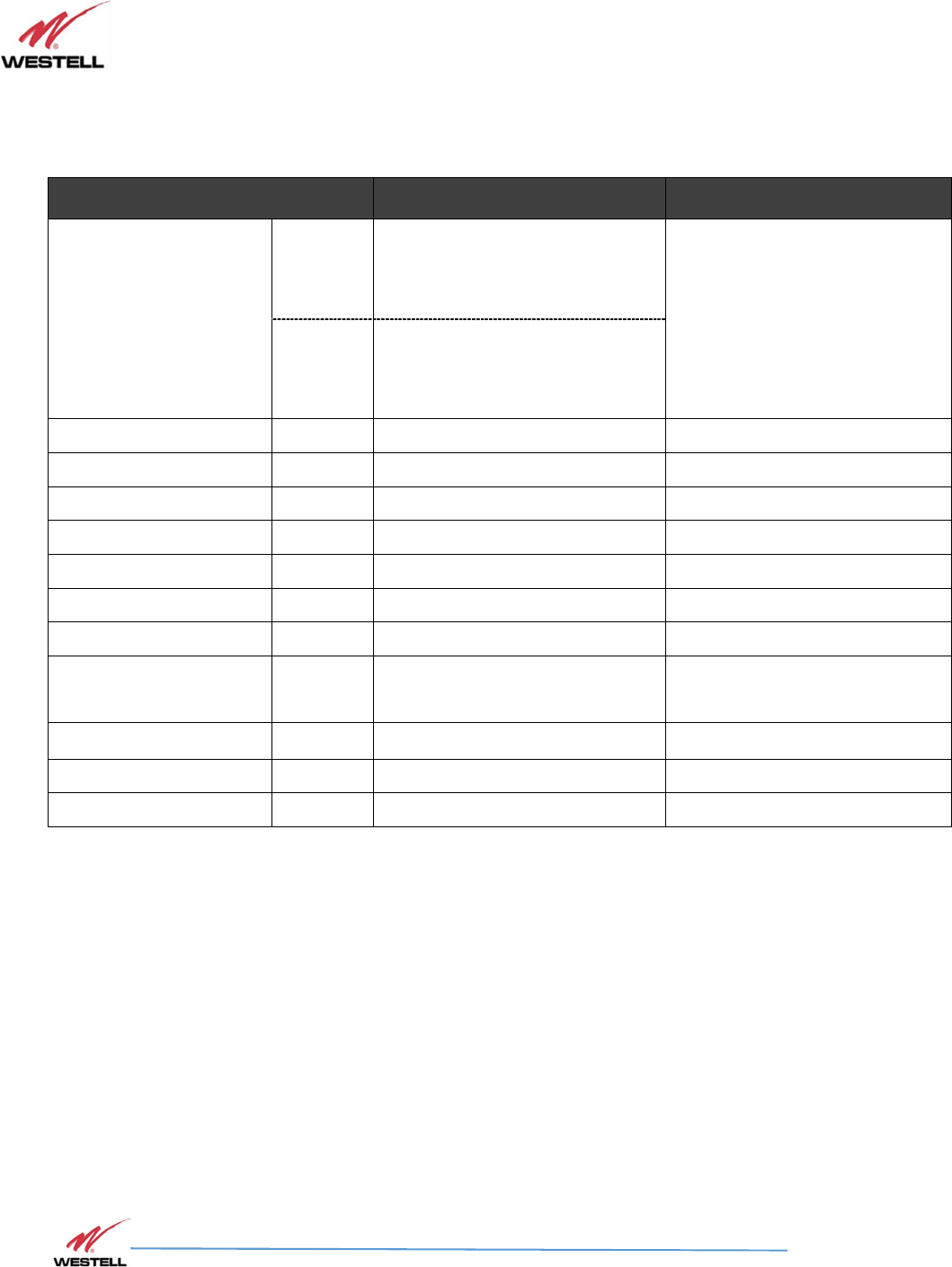
Table 3-1: RF Specifications
Parameter Specification Note
Frequency Range
UL
806~809 MHz Sub-Band1
806~816 MHz Sub-Band2
806~824 MHz Sub-Band3
independently Controlled via the GUI
DL
851~854 MHz Sub-Band1
851~861 MHz Sub-Band2
851~869 MHz Sub-Band3
Linear Output Power UL / DL +33dBm
Gain UL / DL 90dB (±1.0dB)
Gain Adjustment Range UL / DL 30dB±1dB 1dB step
AGC Range UL / DL 25dB (±1dB)
Pass Band Ripple UL / DL ±1.5dB Typ. (Peak-To-Peak 3dB)
3rd Order Intercept Point UL / DL +42.5dBm
Input VSWR UL / DL < 2:1
Maximum Input
No damage Power
UL / DL +10dBm
Propagation Delay UL / DL 4㎲ Max.
Noise Figure UL 5dB Typ. 6.5dB Max.
Input / Output Impedance UL / DL 50 Ohms
PS71090-P8 Product Manual
October 2017, Rev A
WESTELL.COM
©2017 Westell Technologies October 2017; Doc No. CS14000802UM rA
1.877.844.4274 Page 19 of 51
3.2 Power Specification
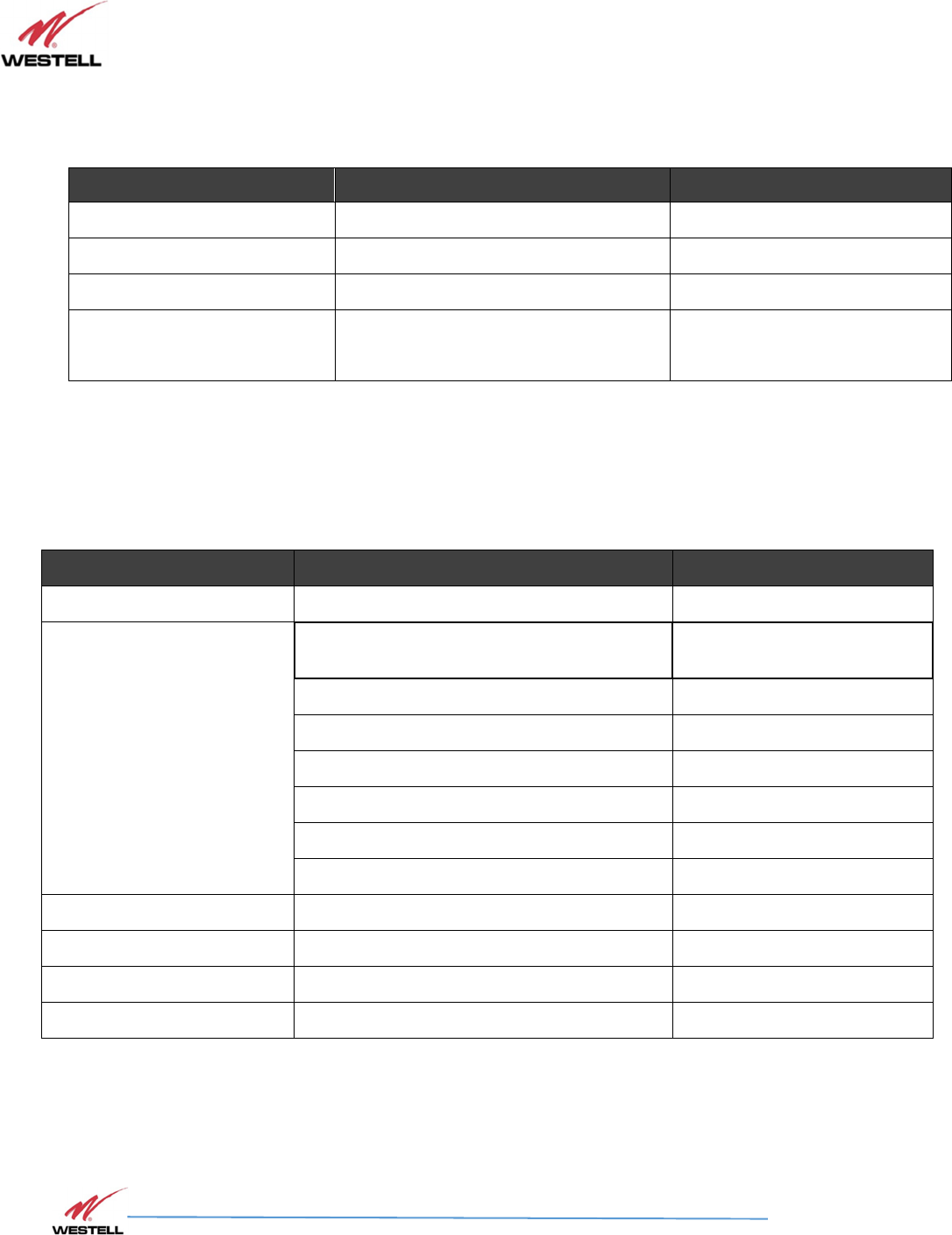
Table 3-2: Power Specifications
Parameter Specification Note
Main Power Input Voltage 110 VAC Internal AC DC Power Supply
Battery / DC Input Voltage 24 VDC to 30 VDC External Battery Power Supply
Power Connector IEC320 AC/DC
Power Consumption
110 AC Input: <100W Max.
24 VDC Input: <65W Max.
<0.9 Amps Max.
<2.7 Amps Max.
3.3 Mechanical Specification
Table 3-3: Mechanical Specifications
Parameter Specification Note
Size 17.7 x 14.1 x 4.7 in L x H x D
Connectors
Donor/Coverage Antenna Ports: 4.3-10 (f) Matting Male Connector Torque
3.7 ft.-lbs.
AC Power In AC cord
DC (Battery) Power In DC cord
Frame Ground Two-Lug Ground
RJ-45 Ethernet-1 (10/100 Base-T) GUI Interface
RJ-45 Ethernet-2 (10/100 Base-T) SNMP Interface
9-Pin D-SUB, female Alarm Relay Interface
Mounting Type Wall-Mount with 4 holes 2 holes in each side
Enclosure Lock Key Lock Two-Key Lock
Heat Dissipation Natural Convection
Finish Red color Paint
PS71090-P8 Product Manual
October 2017, Rev A
WESTELL.COM
©2017 Westell Technologies October 2017; Doc No. CS14000802UM rA
1.877.844.4274 Page 20 of 51
3.4 Environmental Specification
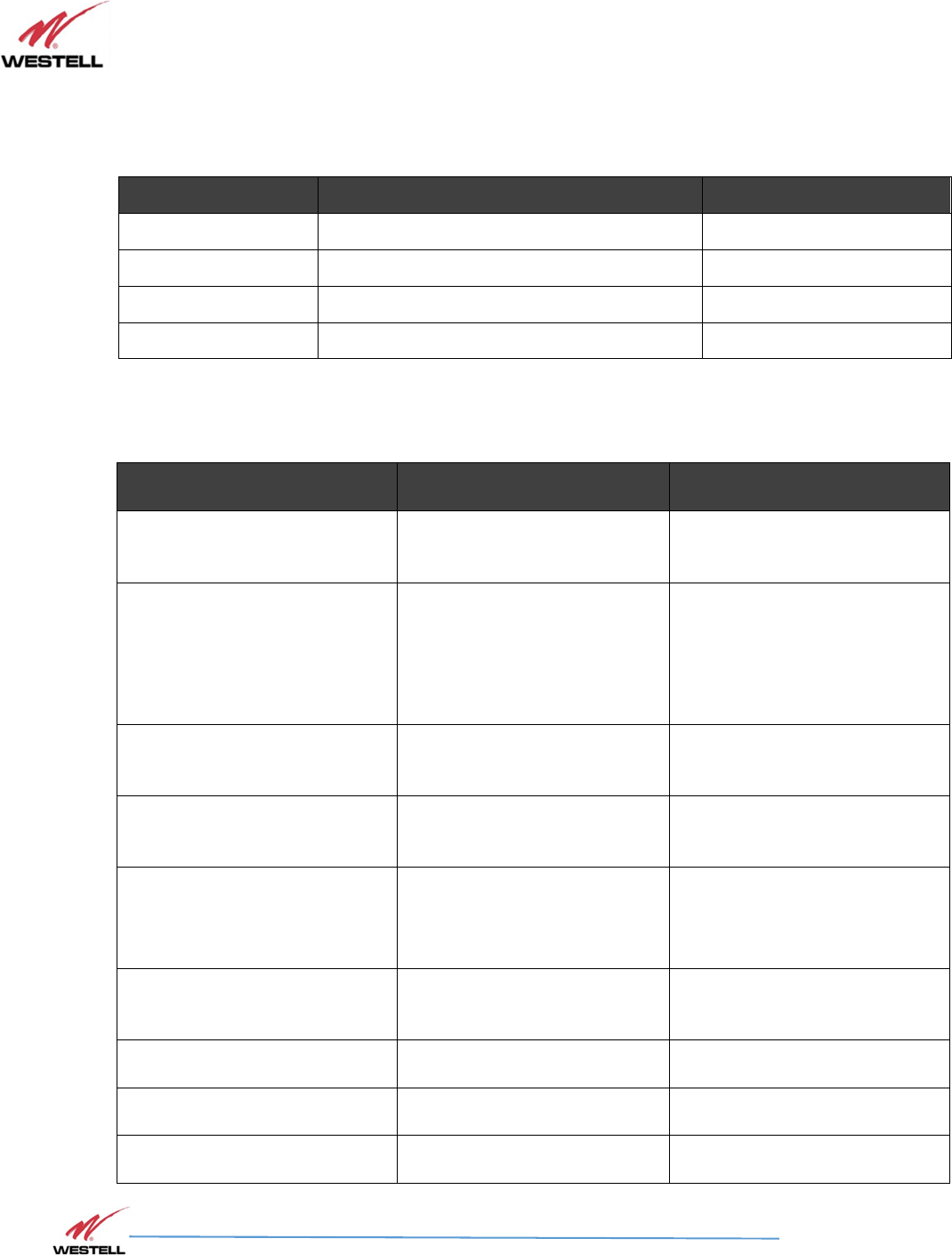
Table 3-4: Environmental Specifications
Parameter Specification Note
Operating Temperature -30°C ~ +50°C (ambient) -22F ~ +122F
Storage Temperature -40°C ~ +60°C (ambient) -40° F to +140° F
Operating Humidity 5% ~ 95%
Environmental IP-65, NEMA 4 Compliance
3.5 GUI Items
Table 3-5: GUI Items
Parameter Specification Note
UL/DL Output Readings 5dBm to 38dBm
Reads and displays the UL/DL
output power
Alarm Readout Displays
PLL LD(Lock Detector), Isolation,
UL/DL shutdown, DC Fail, Relay
Status, UL/DL VSWR, Manual
Amp, Antenna Failure, Power,
UL HPA Fail, DL HPA Fail
Displays alarm status
UL/DL Shutdown Setting
23
dBm to 3
7
dBm
Use to set the peak pow
er
(shutdown level)
UL/DL Gain Setting
/ Attenuation
60
dB to
9
0dB
Gain
0dB to 30dB Attenuation.
Used to set the UL/DL system
gain.
System Location Display
PS71090
-
P8
PS
-
SMR
800
Company, Address, City, State,
Contact
Displays the
Signal Boo
ster
name
and information.
Control Send All Control Page Settings
Used to save settings in the
Control page.
Isolation
Settable to 0db
-
or
-
15dB.
VSWR
Adjustable from 1
-
30
Quit
None
Closes the GUI page.
PS71090-P8 Product Manual
October 2017, Rev A
WESTELL.COM
©2017 Westell Technologies October 2017; Doc No. CS14000802UM rA
1.877.844.4274 Page 21 of 51
Refer to Section 6 System Operation for more information about the GUI.
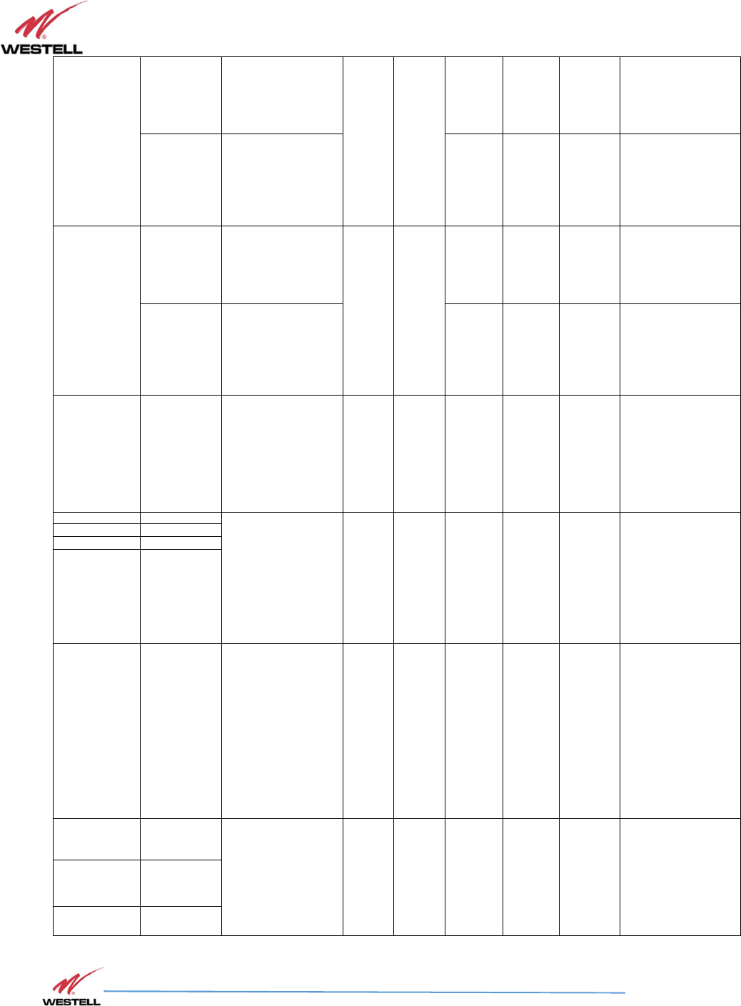
3.6 Alarm Status
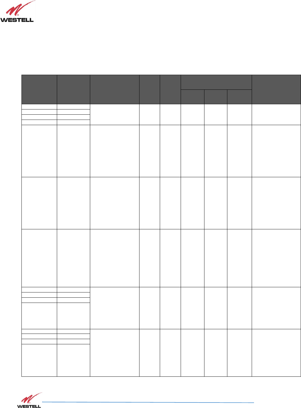
Table 3-6 Alarm Status
Mask
Item
Alarm
Enable[ √
√√
√ ]
Disable[ ]
Condition/
Troubleshooting
AC
Power
Input
DC
Power
Input
Repeater Unit LED
GUI Display
POWER ISO ALARM
AC FAIL [√]
Power : AC
(Normal) O X Solid OFF OFF ALL GREEN
(Normal)
DC FAIL [√]
BATT FAIL (L) [√]
BATT FAIL (H) [√]
PLL LD [√]
PLL LD
(Alarm1 & Alarm2)
X O Solid OFF Blinking
Relay Status : RED
PLL LD : RED
DL/UL HPA : RED
Manual Amp : RED
Rest GREEN
Isolation [√]
Minimum isolation
between Donor &
server Antenna =
Gain+15dB
(Alarm1 & Alarm2)
X O Solid Blinking OFF
Relay Status : RED
Isolation : RED
DL/UL HPA : RED
Manual Amp : RED
Rest GREEN
Shutdown
(DL/UL)
[√]
Too strong signal
from CELL TOWER.
AGC Out of Range.
(Alarm2)
X O Solid OFF Solid
Relay Status : RED
Shutdown (DL/UL) :
RED
DL/UL HPA : RED
Manual Amp : RED
Rest GREEN
AC FAIL [√]
DC ONLY
DC Voltage : 27V
Alarm All Enable
(Alarm1)
X O Solid OFF OFF
Relay Status : RED
AC FAIL : RED
Rest GREEN
DC FAIL [√]
BATT FAIL (L) [√]
BATT FAIL (H) [√]
AC FAIL [ ]
DC ONLY
DC Voltage : 27V
Disable / Mask : AC
FAIL
(Normal)
X O Solid OFF OFF
Relay Status :
GREEN
AC FAIL : RED
Rest GREEN
DC FAIL [√]
BATT FAIL (L) [√]
BATT FAIL (H) [√]
PS71090-P8 Product Manual
October 2017, Rev A
WESTELL.COM
©2017 Westell Technologies October 2017; Doc No. CS14000802UM rA
1.877.844.4274 Page 22 of 51
DL VSWR
[√]
DL VSWR : > set
Value
(Alarm3)
X O
Solid OFF Solid
Relay Status: RED
DL VSWR: RED
Rest GREEN
[ ]
Disable Alarm
(Normal)
Solid OFF OFF
Relay Status:
GREEN
DL VSWR: RED
Rest GREEN
UL VSWR
[√]
UL VSWR : > set
Value
(Alarm3)
X O
Solid OFF Solid
Relay Status: RED
UL VSWR: RED
Rest GREEN
[ ]
Disable Alarm
(Normal)
Solid OFF OFF
Relay Status:
GREEN
UL VSWR: RED
Rest GREEN
Manual Amp [√]
Manual Amp
(Alarm2)
X O Solid OFF Solid
Relay Status: RED
Manual Amp: RED
DL/UL HPA Fail :
RED
Rest GREEN
AC FAIL [ ]
Power : DC
DC Voltage : <23.2V
(+/- 0.3V)
Disable Alarm : AC
FAIL
(Alarm1)
X O Blinking OFF OFF
Relay Status: RED
AC FAIL: RED
DC FAIL: RED
BATT FAIL (LOW):
RED Rest GREEN
DC FAIL [√]
BATT FAIL (L) [√]
BATT FAIL (H) [√]
AC FAIL [ ]
Power : DC X O Blinking OFF OFF
Relay Status: RED
AC FAIL: RED
DC FAIL: RED
BATT FAIL (HIGH):
RED Rest GREEN
DC FAIL [√]
DC Voltage : 28.8V
(+/- 0.3V)
Disable Alarm : AC
FAIL
(Alarm1)
BATT FAIL (L) [√]
BATT FAIL (H) [√]
PS71090-P8 Product Manual
October 2017, Rev A
WESTELL.COM
©2017 Westell Technologies October 2017; Doc No. CS14000802UM rA
1.877.844.4274 Page 23 of 51
DL HPA FAIL [√]
DL HPA FAIL
(Alarm2)
X O Solid OFF Solid
Relay Status: RED
Manual Amp: RED
DL HPA FAIL: RED
Rest: GREEN
UL HPA FAIL [√]
UL HPA FAIL
(Alarm2)
X O Solid OFF Solid
Relay Status: RED
Manual Amp: RED
UL HPA FAIL: RED
Rest: GREEN
DC OVER
CURRENT (UL) [√]
UL Input power too
Strong
(Alarm2)
X O Solid OFF Solid
Relay Status: RED
Manual Amp: RED
UL HPA FAIL: RED
Rest: GREEN
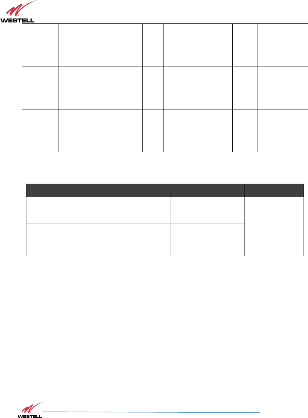
3.7 Alarm Relay
Table 3-7 Alarm Relay
Shutdown Signal
Relay Status
Note
Normally Open NO (pin 2) + CC (pin 3) PIN 1 NC, PIN 2
NO, PIN 3 CC
PIN 4 NC, PIN 5
NO, PIN 6 CC
PIN 7 NC, PIN 8
NO, PIN 9 CC
Normally Closed NC (pin 1) + CC (pin 3)
NOTE
Either method in Table 3-7 would trigger the following alarms: Antenna
Malfunction, PA Failure and Power Failure.
ALARM 1 : System component failure, and/or loss of power – AC/DC (Pin 1,2,3)
ALARM 2 : Active PA System failure / PA system failure (Pin 4,5,6)
ALARM 3 : Antenna failure – Donor and Server VSWR Alarm (Pin7,8,9
)
(See Appendix C for VSWR Alarm Timing Diagram)
PS71090-P8 Product Manual
October 2017, Rev A
WESTELL.COM
©2017 Westell Technologies October 2017; Doc No. CS14000802UM rA
1.877.844.4274 Page 24 of 51
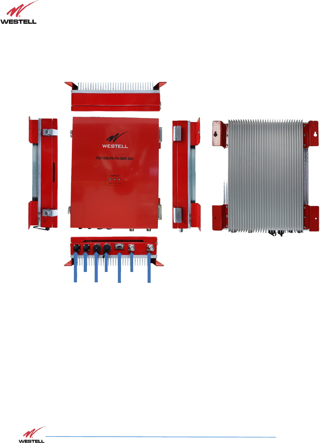
4 Product Appearance
4.1 External Configuration
Figure 4-1: External Product Configuration
AC PWR
BATT
SNMP
GUI
ALARM
RELAY
DONOR
ANT
SERVER
ANT

PS71090-P8 Product Manual
October 2017, Rev A
WESTELL.COM
©2017 Westell Technologies October 2017; Doc No. CS14000802UM rA
1.877.844.4274 Page 25 of 51
5 Installation Guidelines
5.1 Important Installation Guidelines
•
The PS71090 Signal Booster is designed for indoor use only.
•
The PS71090 Signal Booster must be installed in a vertical orientation (i.e. Connectors on the
bottom of the unit).
•
Inadequate isolation between the outside and inside antennas may cause regenerative
feedback in the system.
This feedback can cause the amplifier to emit a continuous signal at maximum
Amplitude, and, in some cases, interfere with normal operation of the donor site.
Careful consideration of the layout and placement of the system is imperative to
minimize this possibility and to minimize the amount of signal leaking from the
Building.
•
Do not disassemble the Signal Booster.
DANGER!
•
Refer to the 1.3 Safety Guidelines section for proper antenna selection and
installation. To avoid serious injury, death and/or damage to the Signal
Booster, do not install donor or server antennas near overhead power lines or
high power components. Allow enough distance so that falling antennas
would not come in contact with those components.
•
Electric shock may occur if the Signal Booster is installed in close proximity to
water.
WARNING!
•
Amplifier or handset damage may occur if a handset is connected directly to
the Signal Booster or to the coax that leads to the Signal Booster.
•
The PS71090 Signal Booster must be connected to ground for protection.
•
We recommend that installers do not wear jewelry or metal accessories when
installing this Signal Booster.
•
Do not place cables or tools that may damage the Signal Booster in close
proximity to it.
•
Check the installation site for hazardous conditions such as water-covered
floors or badly worn or damaged cables prior to installation.
•
Lifespan and performance of the Signal Booster may be reduced if the unit is
operating outside its nominal temperature range.

PS71090-P8 Product Manual
October 2017, Rev A
WESTELL.COM
©2017 Westell Technologies October 2017; Doc No. CS14000802UM rA
1.877.844.4274 Page 26 of 51
CAUTION
•
Close proximity to the donor or server antennas with the Signal
Booster in operation may expose users or installers to RF fields that
exceed FCC limits for human exposure.
•
Turn power to the Signal Booster off when connecting or disconnecting
cables.
5.2 Donor Antenna Installation Guidelines
•
Accurately determine the azimuth to the donor site. Obtain the donor site information and
approval from the service provider/carrier.
•
Ensure that the radiation path to the donor site is unobstructed.
•
Mount the donor antenna at or toward the edge of the roof, in the direction of the donor
site. Avoid having the RF signal from the donor pass above the location(s) of the service
antennas. Normally, the service antennas are installed behind and below the donor antenna,
as viewed from above. This approach helps avoid interference and feedback to and from the
service antennas.
•
Normally, mounting the donor antenna higher will allow a less obstructed path to the donor
site. However, in high traffic metro areas, avoid mounting the donor antenna higher than
necessary, as the quality of the donor signal may become less stable and it is more likely to
encounter adjacent channel interference.
•
When possible, shield the rear of a donor antenna by locating it so that any HVAC units
and/or penthouse structures are behind the antenna, relative to the donor cell site location.
5.3 Indoor Antenna Installation Guidelines
•
Use omnidirectional antennas (see section 2.4. Optional Accessories) indoors and locate
them centrally with respect to the intended coverage area to minimize signal leakage to the
outside. Only use directional antennas indoors in special cases when higher gain and
directionality would be helpful and RF exposure limits will not be exceeded.
•
To avoid Signal Booster uplink overload and gain limiting, mount the indoor antennas away
from areas where mobile subscribers frequently use their phones / radios, such as desks or
dispatch areas. Note: If the signal level from Antenna at the UL service port is >-12dBm,
Add external attenuation to avoid shutdown alarm
•
To determine the quantity and locations of indoor antennas, measure Received Signal
Strength Indication (RSSI) using DM Tool software to determine areas of weak signals. These
are the approximate areas where indoor antennas may be needed.
•
Be aware that the signal from an indoor antenna, in most cases, can be expected to
penetrate approximately two standard sheet rock walls to reach users. If the signal must
travel through more than two walls, or if the walls are made of materials other than sheet
rock, it may be necessary to split the available signal and add more antennas.
PS71090-P8 Product Manual
October 2017, Rev A
WESTELL.COM
©2017 Westell Technologies October 2017; Doc No. CS14000802UM rA
1.877.844.4274 Page 27 of 51
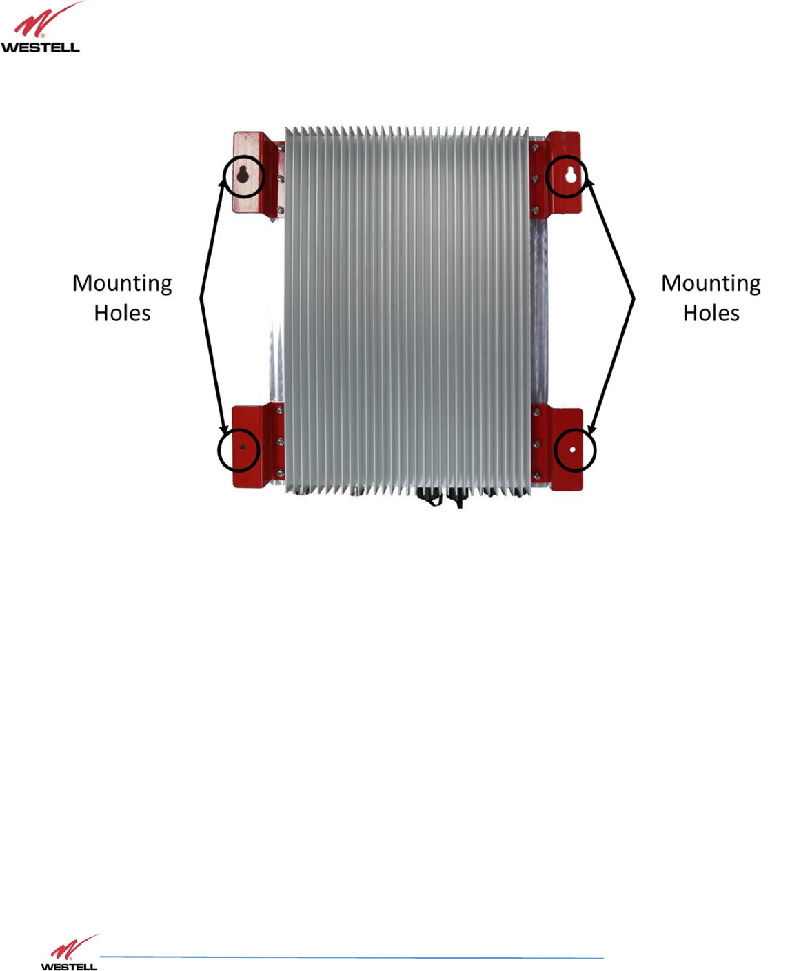
5.4 Mounting the Signal Booster
Follow the instructions in this section to mount the Signal Booster on a wall.
Figure 5-1: Signal Booster Mounting
1.
Using the PS71090 as a template, mark the four (4) locations for the wall
anchoring system screws.
2.
Move the PS71090 unit and drill the mounting holes at the marks in the wall.
Install a wall anchor in each of the four (4) drilled holes.
3.
Install the top two (2) screws into the anchors, leaving enough room to slide the
screws into the oblong holes of the top of the unit’s mounting positions.
4.
Once the Unit is hung on the top two (2) screws finish fastening the top screws.
5.
Install the bottom two (2) screws into the anchors, fastening the Unit to the wall.
PS71090-P8 Product Manual
October 2017, Rev A
WESTELL.COM
©2017 Westell Technologies October 2017; Doc No. CS14000802UM rA
1.877.844.4274 Page 28 of 51
5.5 Verifying the Physical System Setup
•
Check all cables for shorts and opens. Verify that there are no cables with loose or poor
connections. RF leakage could cause oscillation to occur under some conditions.
•
If the rooftop antenna (donor antenna) is directional, check it for proper alignment along
the calculated compass heading. Typically, the directional antenna would be aimed at the
same site that your handset uses, but that may not always be the case.
•
If cables and alignment are acceptable, and a problem persists, use a spectrum analyzer to
examine the signal environment in which the unit is operating. The existence of strong
adjacent channel signals within the frequency band(s) can cause the AGC to reduce the
amplifier’s gain or cause alarms. In some cases, additional filtering or attenuation may be
required to reject these unwanted signals. In some instances, the donor antenna can be
reoriented horizontally to place the interference source in an antenna pattern null.
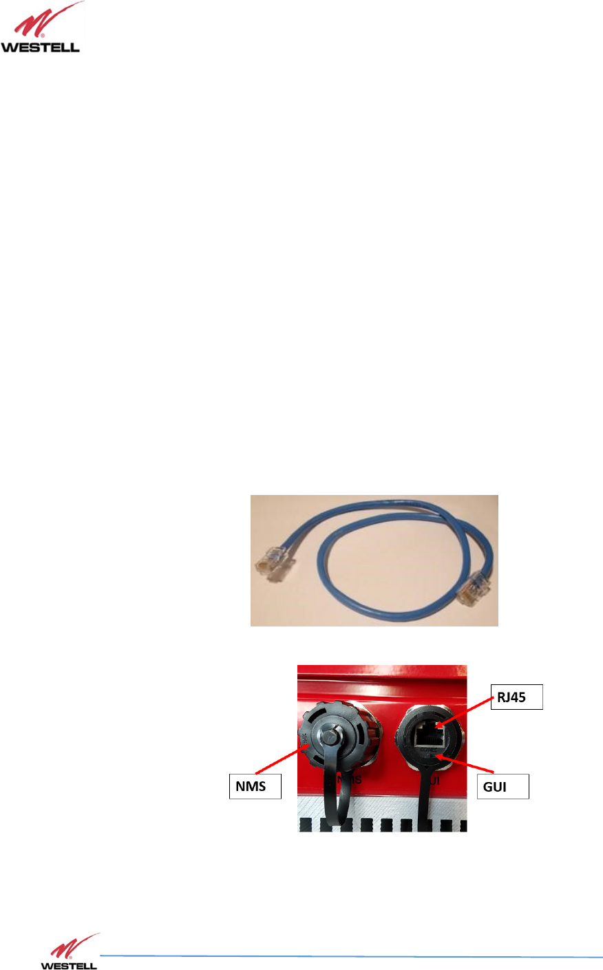
5.6 Controlling the Signal Booster
Control and monitoring the Signal Booster requires that a properly configured computer with Westell
PS71090 control software installed is connected via an Ethernet cable, such as the one shown in
Figure 5-2A. Connect the Ethernet cable from the Network Interface port of a computer to the GUI
port on the bottom end panel of the Signal Booster.
Figure 5-2A: Ethernet Cable
Figure 5-2B: Ethernet Connectors
PS71090-P8 Product Manual
October 2017, Rev A
WESTELL.COM
©2017 Westell Technologies October 2017; Doc No. CS14000802UM rA
1.877.844.4274 Page 29 of 51
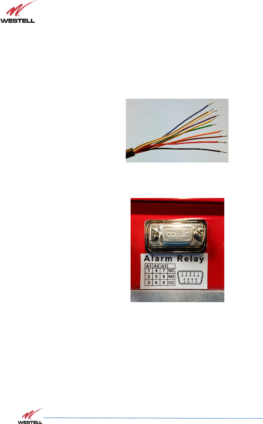
5.7 Connecting to the Alarm Relay Panel
Use the provided Alarm Relay Serial Cable to connect the PS71090 Public Safety Signal Booster to the
alarm relay panel. If the provided cable is not long enough for your system, you will need to build
one.
1.
Strip the outer serial cable insulation back to expose the inner conductors, Figure
5-3.
2.
Strip back the insulation on the ends of each conductor. (Tin wires as needed.)
Figure 5-3:
Stripped Alarm Wire
3.
Remove the protective cover on the Alarm Relay 9 position D-Sub connector.
Figure 5-4: Alarm Relay 9 Position D-Sub Connector
PS71090-P8 Product Manual
October 2017, Rev A
WESTELL.COM
©2017 Westell Technologies October 2017; Doc No. CS14000802UM rA
1.877.844.4274 Page 30 of 51
4.
Connect the 9 position D-Sub connector at one end of the serial cable to the
Alarm Relay connector on the PS71090, Figure 5-6. Be sure to fasten the
connector screws securely.
Figure 5-5:
Alarm Relay Cable Connected to Signal Booster
5.
Connect the stripped end of the serial cable to the alarm relay panel. Refer to
Table 5-1 for connection information.
Table 5-1: Alarm Relay Connections
Pin
Number
Contact Type
Cond
uctor Color
(supplied Cable)
Alarm Number
1
NC
(Normally Closed)
Black
Alarm One
2
NO
(Normally Open)
Brown
Alarm One
3
CC
(Common Connection)
Red
Alarm One
4
NC
(Normally Closed)
Orange
Alarm Two
5
NO
(Normally Open)
Yellow
Alarm Two
6
CC
(Common Connection)
Green
Alarm Two
7
NC
(Normally Closed)
Bl
ue
Alarm Three
8
NO
(Normally Open)
Violet
Alarm Three
9
CC
(Common Connection)
Grey
Alarm Three
White
Unused
PS71090-P8 Product Manual
October 2017, Rev A
WESTELL.COM
©2017 Westell Technologies October 2017; Doc No. CS14000802UM rA
1.877.844.4274 Page 31 of 51
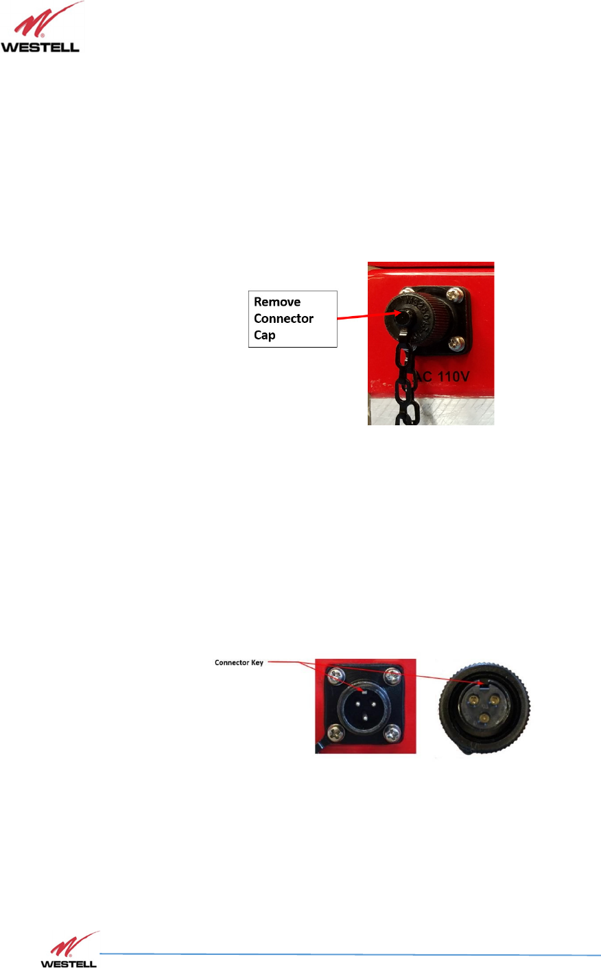
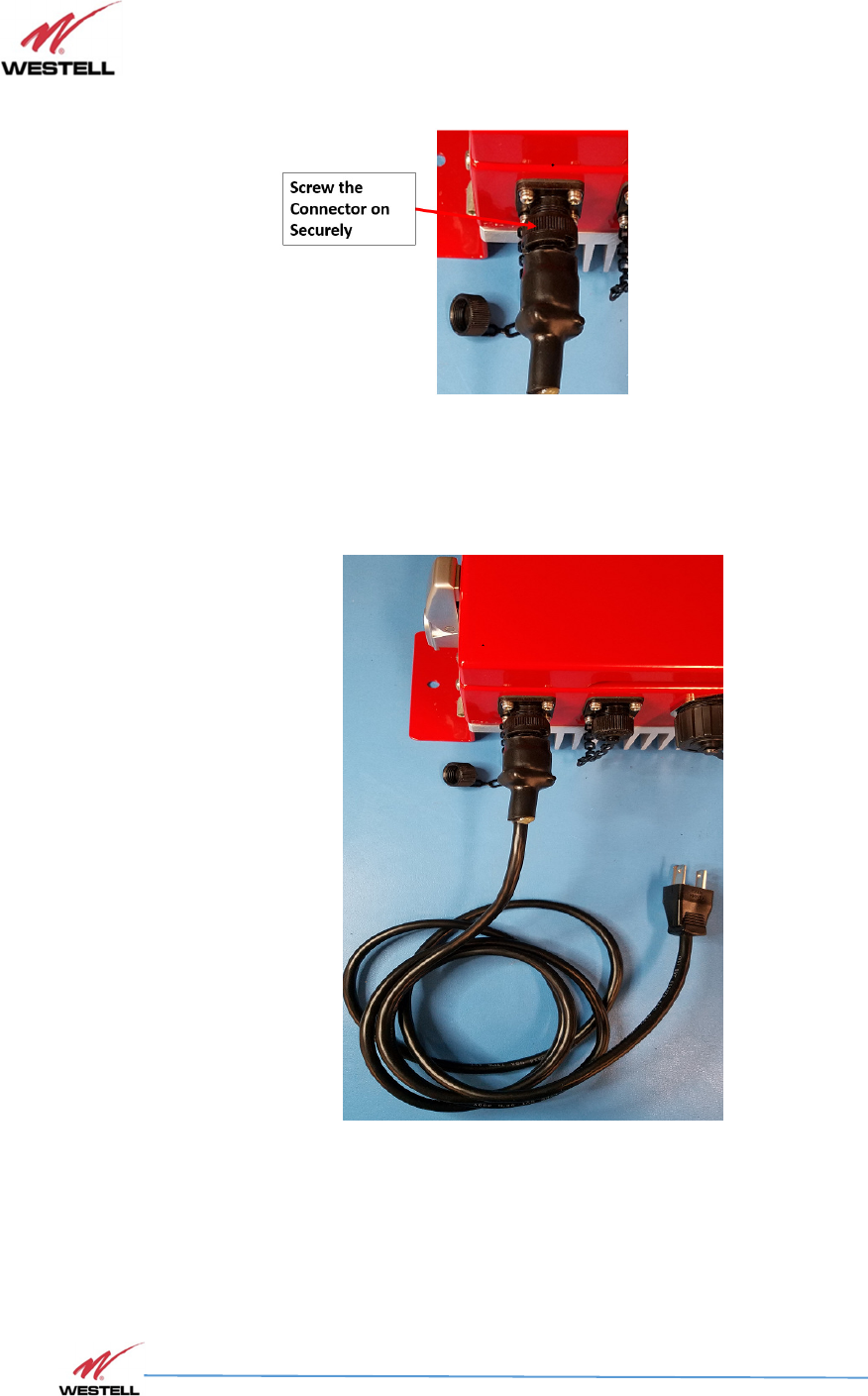
5.8 Connecting the Power Cable
Use the provided AC Power Cable to connect the PS71090 Public Safety Signal Booster to an AC
power source.
1.
Remove the cap from the AC 110V power connector on the Signal
Booster, Figure 5-6.
Figure 5-6: Remove the Power Connector Cap
2.
Connect the power cable to the AC 110V power connector on the Signal
Booster, Figure 5-7.
NOTE
The Signal Booster connector and the cable connector are keyed as shown in Figure 5-7.
Figure 5-7: Connector Keys
PS71090-P8 Product Manual
October 2017, Rev A
WESTELL.COM
©2017 Westell Technologies October 2017; Doc No. CS14000802UM rA
1.877.844.4274 Page 32 of 51
3.
Screw the connector on securely.
Figure 5-8: Power Cable Connected to Signal Booster
4.
When the Signal Booster is properly set up and ready to have power applied,
plug the other end into the 110VAC outlet.
Figure 5-9: Power Cable Connected to Signal Booster
PS71090-P8 Product Manual
October 2017, Rev A
WESTELL.COM
©2017 Westell Technologies October 2017; Doc No. CS14000802UM rA
1.877.844.4274 Page 33 of 51
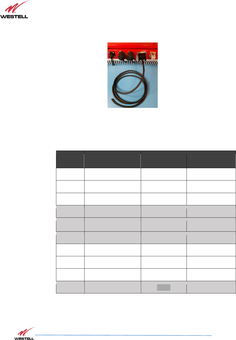
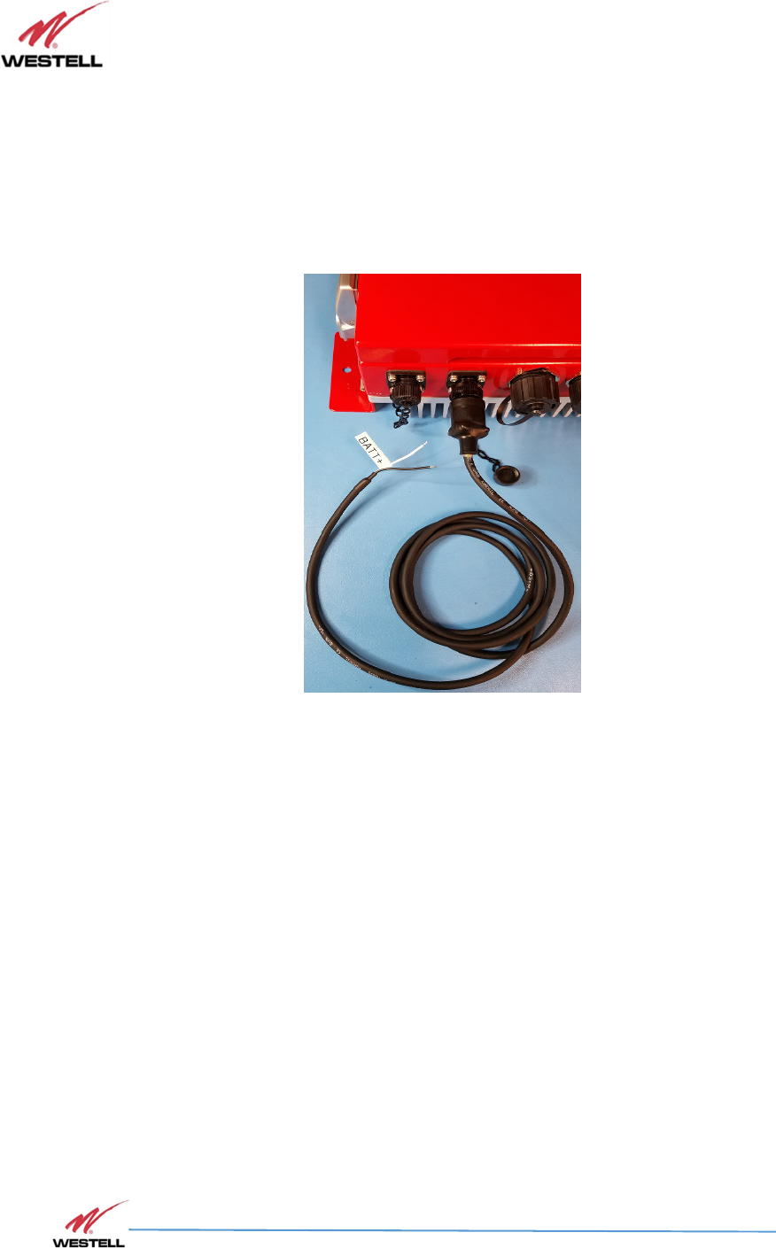
5.9 Connecting the Battery Back-up Cable
Use the provided DC Power Cable to connect the PS71090 Public Safety Signal Booster to a 24-30VDC
Battery Back-up / power source. (White = positive, Black = Negative)
Figure 5-10: Battery Cable Connected to Signal Booster
PS71090-P8 Product Manual
October 2017, Rev A
WESTELL.COM
©2017 Westell Technologies October 2017; Doc No. CS14000802UM rA
1.877.844.4274 Page 34 of 51
6 System Operation
6.1
6.16.1
6.1 Operating the Program
Operating the Program Operating the Program
Operating the Program
Access the PS71090 Public Safety Signal Booster using the provided PS71090-P8 PS-SMR800 software
through a LAN connection. The Signal Booster ships with the IP address 192.168.1.150 on the GUI
port.
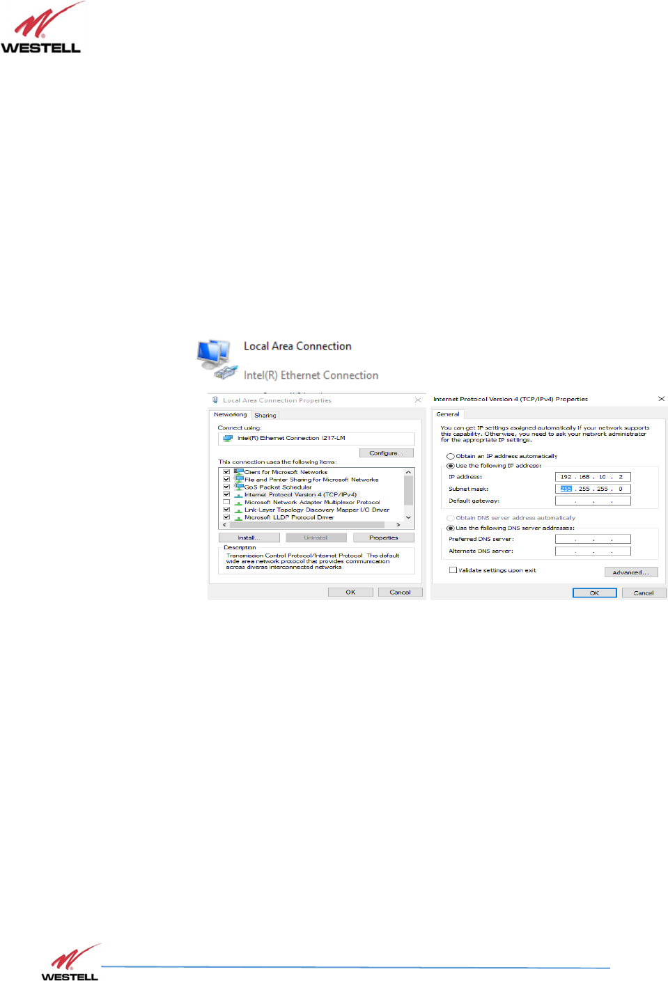
To connect directly to the Signal Booster from a laptop or PC with a crossover CAT-5E cable or over a
LAN, change the TCP/IP settings on your computer to enable a connection to a host that has a static
IP.
Open Control Panel\All Control Panel Items\Network Connections
Choose appropriate Local area connection:
Figure 6.1: Network Connection Set-up
1) Select Use the following IP Address
Use the following IP AddressUse the following IP Address
Use the following IP Address and enter the IP address 192.168.1
192.168.1192.168.1
192.168.1.x,
.x,.x,
.x,
where ‘x’ is any number from 2 to 254, inclusive, other than 150.
e.g. Set Computer IP to 192.168.1.2
2) Ensure that the subnet mask is set to 255.255.255.0.
NOTE
Refer questions about these settings to your IT department.
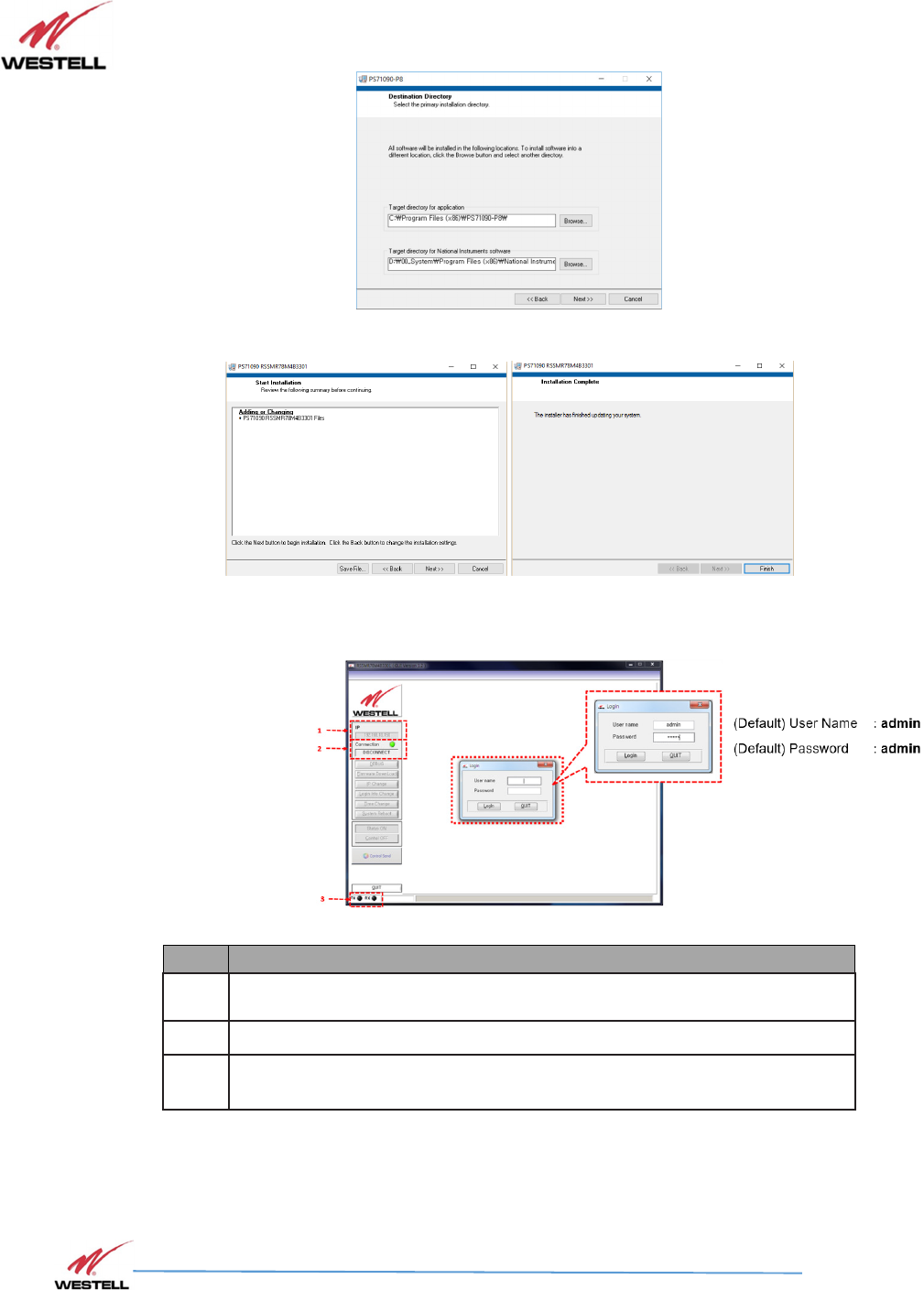
3) Navigate to the RSSMR78M4B3301 directory- on the included USB drive.
4) Locate Setup application software file and double-click to install, as seen below.
PS71090-P8 Product Manual
October 2017, Rev A
WESTELL.COM
©2017 Westell Technologies October 2017; Doc No. CS14000802UM rA
1.877.844.4274 Page 35 of 51
Figure 6.2: Destination Directory
Figure 6.3: Software Installation
5) Click Next and Finish
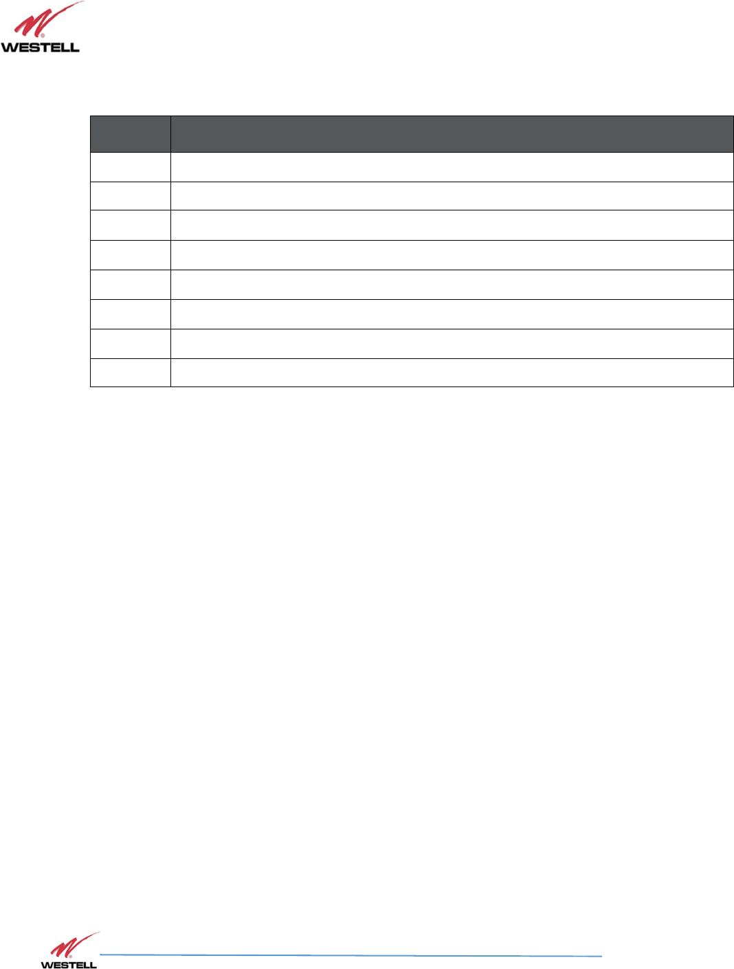
Figure 6.4: PS71090 GUI Log-In
Item
Description
1 IP Address Field (editable when Connect button is displayed)
2 Connect/Disconnect toggle button
3 TX/RX LED indicates the state of communication with the Signal Booster
and GUI
6) Verify that the IP address in the upper left of the page is correct 192.168.1.150, if it is not, edit
it in the IP Address field.
7) Click the Connect button. The button label changes to Disconnect.
PS71090-P8 Product Manual
October 2017, Rev A
WESTELL.COM
©2017 Westell Technologies October 2017; Doc No. CS14000802UM rA
1.877.844.4274 Page 36 of 51
6.2
6.26.2
6.2
Status
StatusStatus
Status
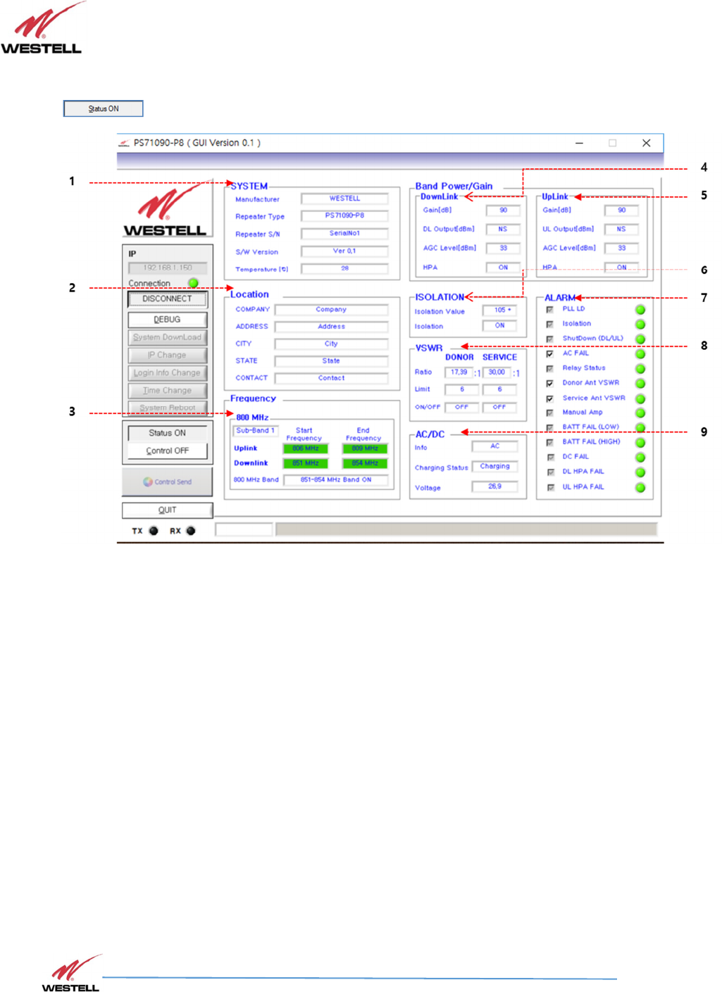
Clicking the Status button in the menu on the left of the page changes the button text to
and displays the Status Mode page, described in this section.
PS71090-P8 Product Manual
October 2017, Rev A
WESTELL.COM
©2017 Westell Technologies October 2017; Doc No. CS14000802UM rA
1.877.844.4274 Page 37 of 51
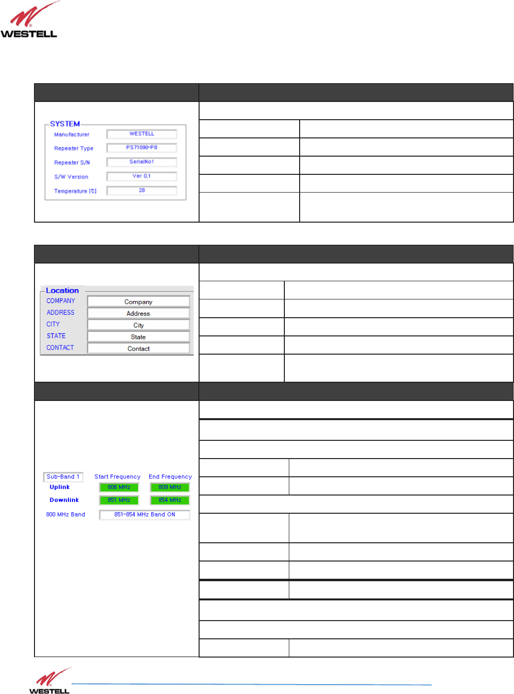
Figure 6-5: Status Mode Page
Item # Section
1
System Not User-Configurable/Informational Only
Manufacture Displays the Signal Booster’s manufacturer
Signal Booster Type Displays Signal Booster Model Number
Signal Booster S/N Displays Signal Booster Serial Number
S/W Version Displays firmware version of the control board
Temperature Displays internal temperature of the Signal
Booster
Item # Section
2
Location
Company Company information display
Address Address information display
City City information display
State State information display
Contact Contact information display
Item # Section
3
800 MHz
Sub-band 1
Uplink
Start Frequency Displays sub-band 1 uplink Start frequency
Stop Frequency Displays sub-band 1 uplink Stop frequency
Downlink
Start Frequency Displays the sub-band 1 downlink start
frequency
Stop Frequency Displays sub-band 1 downlink Stop frequency
800MHz Band Allows sub-band 1 to be set to Select
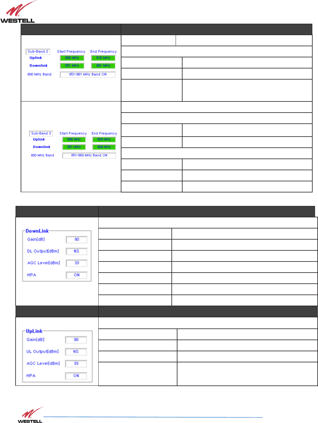
Sub-band 2
Uplink
Start Frequency Displays sub-band 2 uplink Start frequency
PS71090-P8 Product Manual
October 2017, Rev A
WESTELL.COM
©2017 Westell Technologies October 2017; Doc No. CS14000802UM rA
1.877.844.4274 Page 38 of 51
Item # Section
Stop Frequency Displays sub-band 2 uplink Stop frequency
Downlink
Start Frequency Displays sub-band 2 downlink start frequency
Stop Frequency Displays sub-band 2 downlink Stop frequency
800MHz Band
Allows sub-band 2 to be set to Select
Sub-band 3
Uplink
Start Frequency
Displays sub-band 3 uplink Start frequency
Stop Frequency Displays sub-band 3 uplink Stop frequency
Downlink
Start Frequency Displays sub-band 3 downlink Start frequency
Stop Frequency Displays sub-band 3 downlink Stop frequency
800MHz Band Allows sub-band 3 to be set to Select
Item # Section
4
Downlink
Gain [dB] Displays downlink gain
Output (dBm) Displays Output value
AGC Level [dBm] Displays Automatic Gain Control Level
HPA Displays Down link HPA On/Off
Item # Section
5
Uplink
Gain (dB) Displays status of the uplink gain
UL Output [dBm] Displays uplink output level
ALC Level [dBm] Displays Automatic Gain Control Level
HPA Displays Up link HPA On/Off
PS71090-P8 Product Manual
October 2017, Rev A
WESTELL.COM
©2017 Westell Technologies October 2017; Doc No. CS14000802UM rA
1.877.844.4274 Page 39 of 51
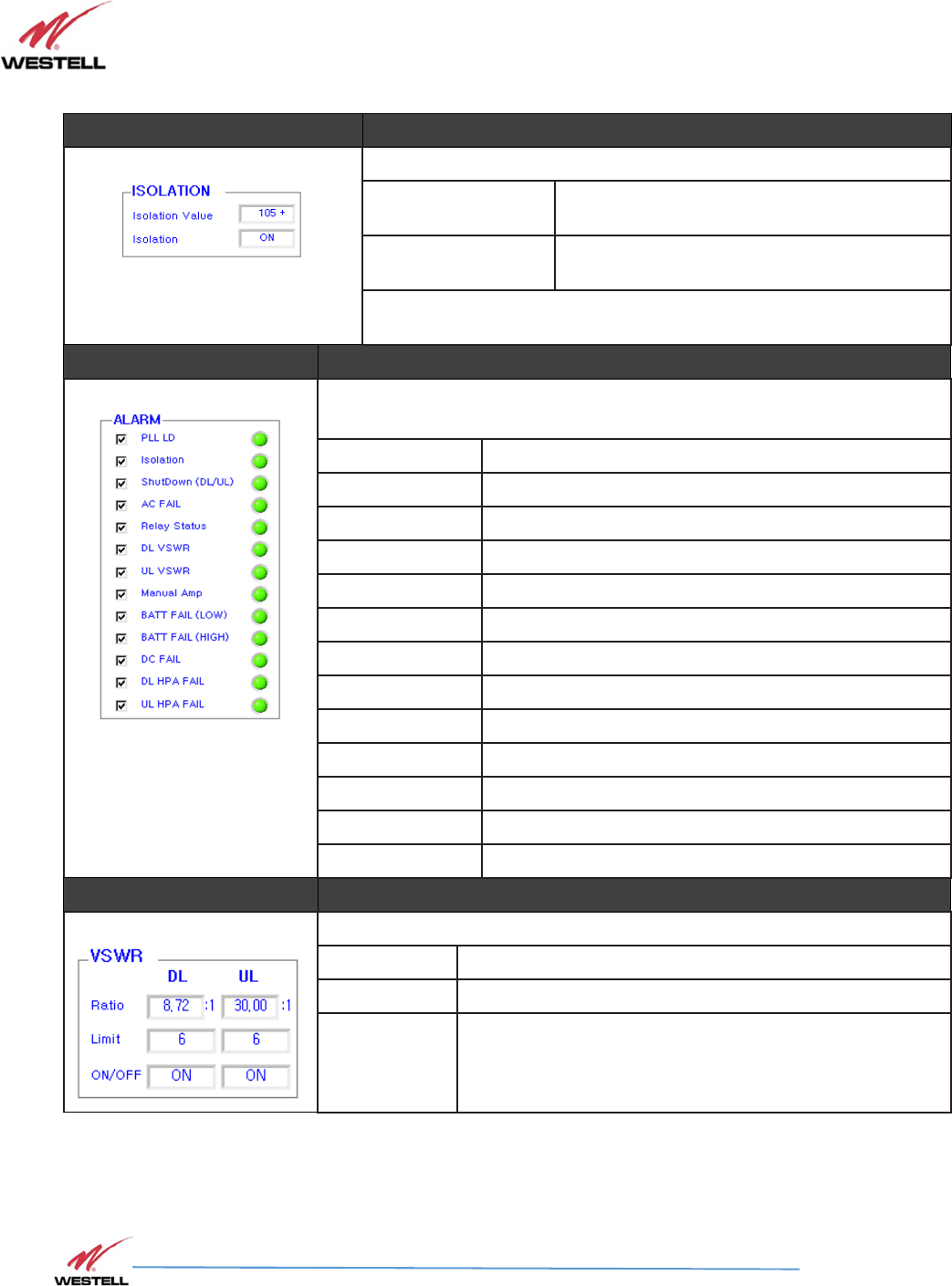
Item # Section
6
Isolation
Isolation Value When power is on, an isolation check is
performed and the values are displayed
Isolation The isolation check can be performed with the
RF on or off
Note: Neither the isolation check, nor recheck, will indicate a change
in power levels if the unit’s own power has been switched off.
Item # Section
7
Alarm Status Not User-Configurable/Informational Only
( GREEN = Normal; RED = Alarm )
PLL LD Display alarm
Isolation Display alarm
Shutdown (DL/UL)
Display alarm
DC Fail Display alarm
Relay Status Display alarm
DL VSWR DL Path VSWR check
UL VSWR UL Path VSWR check
Manual Amp User HPA OFF Alarm
BATT FAIL (LOW)
BATT Low Power Alarm
BATT FAIL (HIGH)
BATT High Power Alarm
DC FAIL BATT / AC Power Alarm
DL HPA FAIL DL Path HPA Alarm
UL HPA FAIL UL Path HPA Alarm
Item # Section
8
VSWR ( DL / UL )
Ratio VSWR Ratio Status Display, 0.00 to 30.00
Limit VSWR Ratio Alarm Limit , Set 0.00 to 30.00
On/Off VSWR Alarm Display Enable(On)/Display(Off)

PS71090-P8 Product Manual
October 2017, Rev A
WESTELL.COM
©2017 Westell Technologies October 2017; Doc No. CS14000802UM rA
1.877.844.4274 Page 40 of 51
Item # Section
9
AC/DC
Info AC or BATT Status Display
Charge Status Charge Status Display Charge / Discharge
Voltage AD or DC Voltage Display 0.0 ~ 29.0
6.3
6.3 6.3
6.3 Control
ControlControl
Control
Clicking the Control button in the menu on the left of the page changes the button text to
and displays the Control Mode page, described in this section.
PS71090-P8 Product Manual
October 2017, Rev A
WESTELL.COM
©2017 Westell Technologies October 2017; Doc No. CS14000802UM rA
1.877.844.4274 Page 41 of 51
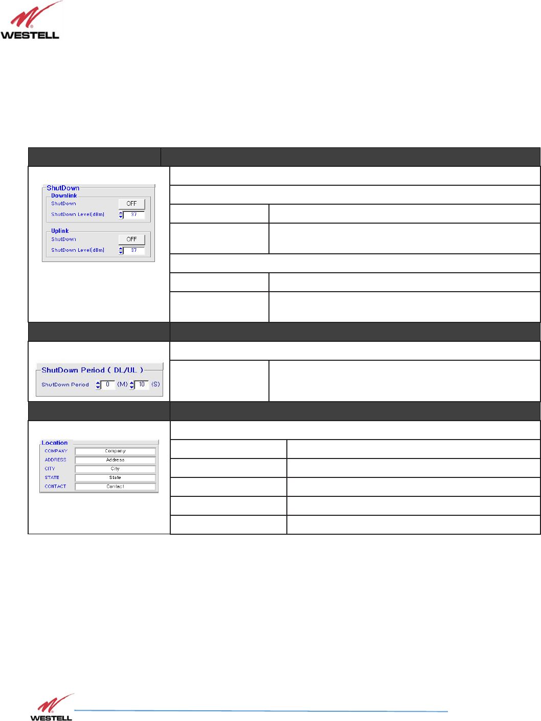
Figure 6-6: Control Mode Page
Item # Section
1
Shutdown Allows the shut-down level to be set
Downlink
Shutdown Allows the downlink shutdown level to be set to on or off.
Shutdown Level
[dBm]
Allows the maximum shutdown level to be set between
23 and 37
Uplink
Shutdown Allows the uplink shut down level to be set to on or off
Shutdown Level
[dBm]
Allows the maximum shutdown level to be set between
23 and 37
Item # Section
2
Shutdown Period Allows the shutdown period to be set
Shutdown Period
Allows the shutdown period to be set in minutes and
seconds.
Item # Section
3
Location
Company Company information display
Address Address information display
City City information display
State State information display
Contact Contact information display
PS71090-P8 Product Manual
October 2017, Rev A
WESTELL.COM
©2017 Westell Technologies October 2017; Doc No. CS14000802UM rA
1.877.844.4274 Page 42 of 51
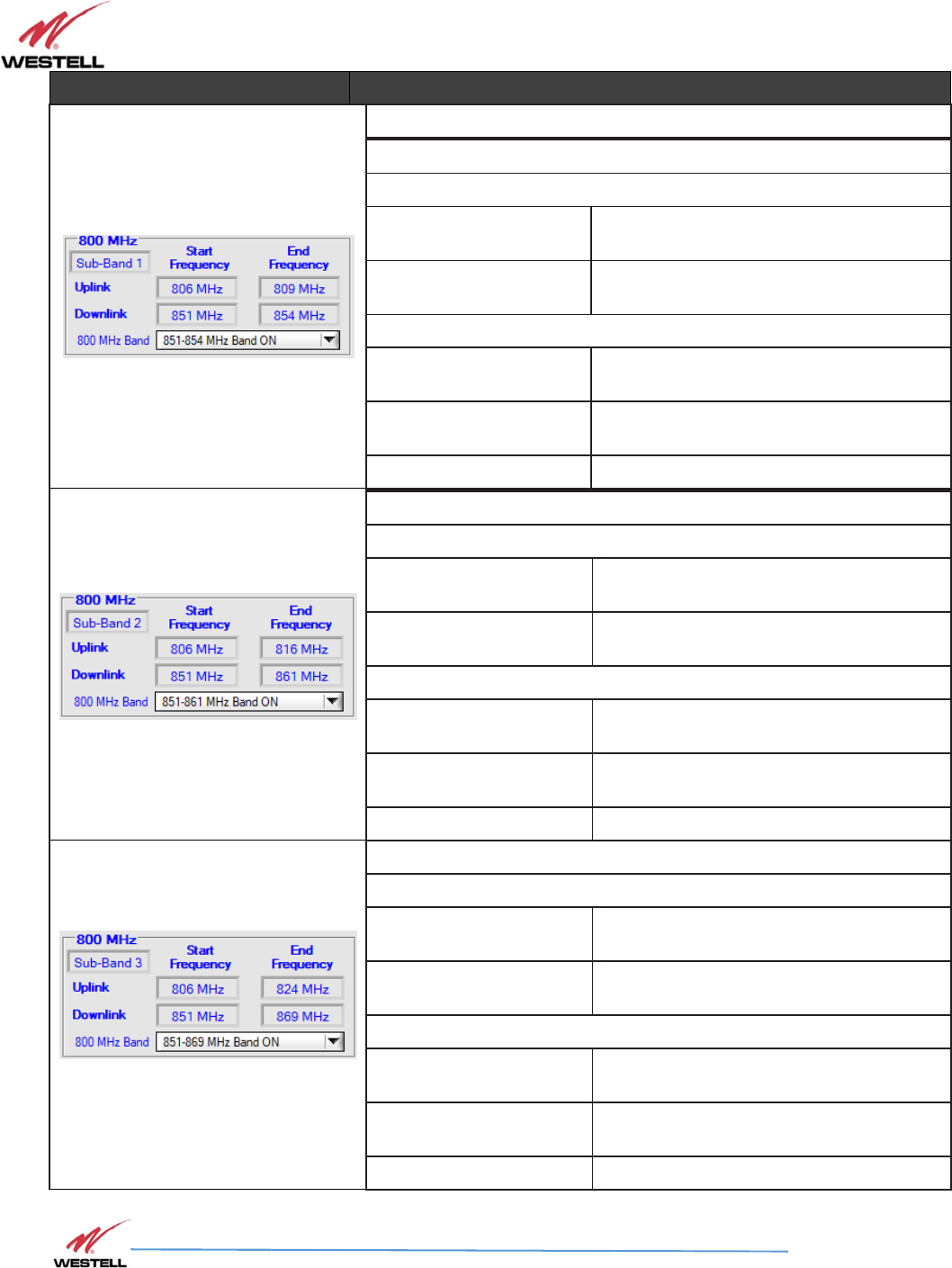
Item # Section
4
Band Select: 800 MHz
Sub-band 1
Uplink
Start Frequency Displays sub-band 1 uplink Start
frequency
Stop Frequency Displays sub-band 1 uplink Stop
frequency
Downlink
Start Frequency Displays sub-band 1 downlink Start
frequency
Stop Frequency Displays sub-band 1 downlink Stop
frequency
800 MHz Band Allows sub-band 1 to be set to Select
Sub-band 2
Uplink
Start Frequency Displays sub-band 2 uplink Start
frequency
Stop Frequency Displays sub-band 2 uplink Stop
frequency
Downlink
Start Frequency Displays sub-band 2 downlink start
frequency
Stop Frequency Displays sub-band 2 downlink Stop
frequency
800 MHz Band Allows sub-band 2 to be set to Select
Sub-band 3
Uplink
Start Frequency Displays sub-band 3 uplink Start
frequency
Stop Frequency Displays sub-band 3 uplink Stop
frequency
Downlink
Start Frequency Displays sub-band 3 downlink start
frequency
Stop Frequency Displays sub-band 3 downlink Stop
frequency
800 MHz Band Allows sub-band 3 to be set to Select
PS71090-P8 Product Manual
October 2017, Rev A
WESTELL.COM
©2017 Westell Technologies October 2017; Doc No. CS14000802UM rA
1.877.844.4274 Page 43 of 51
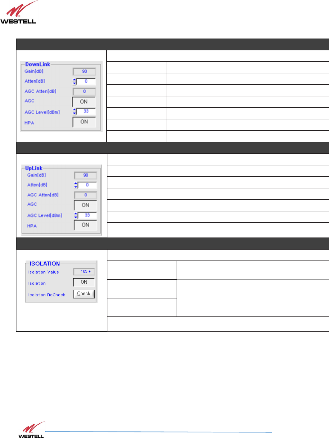
Item # Section
5
Downlink
Gain [dB] Displays downlink gain
Atten [dB] Sets attenuation value
AGC Atten [dB] Displays attenuation value controlled by AGC
AGC Control Auto Level Control Function On/Off
AGC Level [dBm] Sets the unit’s maximum ALC output value
HPA Down link HPA On/Off
Item # Section
6
Gain (dB) Displays status of the uplink gain
Atten [dB] Sets the attenuation value
AGC Atten [dB] Displays attenuation value controlled by AGC
AGC Control Auto Gain Control Function On/Off
AGC Level [dBm] Sets the unit’s maximum AGC output value
HPA Uplink HPA On/Off
Item # Section
7
Isolation
Isolation Value When power is on, an isolation check is performed
and the values display.
Isolation The isolation check can be performed with the RF
on or off.
Isolation Recheck The isolation check can be performed with the RF
on or off.
Note
: Neither the isolation check nor recheck will indicate a change in power
levels if the unit’s own power has been switched off.
PS71090-P8 Product Manual
October 2017, Rev A
WESTELL.COM
©2017 Westell Technologies October 2017; Doc No. CS14000802UM rA
1.877.844.4274 Page 44 of 51
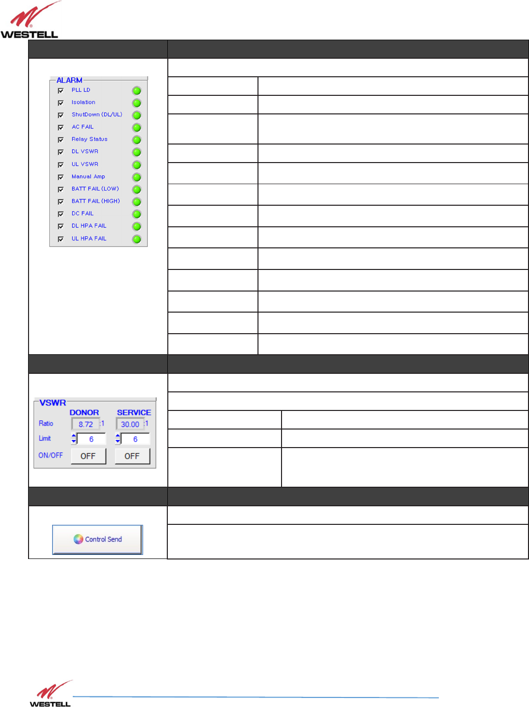
Item # Section
8
Alarm ( GREEN = Normal; RED = Alarm )
PLL LD Displays alarm
Isolation Displays alarm
Shutdown
(DL/UL)
Displays alarm
DC Fail Displays alarm
Relay Status Displays alarm
DL VSWR DL Path VSWR check
UL VSWR UL Path VSWR check
Manual Amp User HPA OFF Alarm
BATT FAIL (LOW)
BATT Low Power Alarm
BATT FAIL (HIGH)
BATT High Power Alarm
DC FAIL BATT / AC Power Alarm
DL HPA FAIL DL Path HPA Alarm
UL HPA FAIL UL Path HPA Alarm
Item # Section
9
VSWR
DL/UL
Ratio VSWR Ratio Status Display, 0.00 to 30.00
Limit VSWR Ratio Alarm Limit , Set 0.00 to 30.00
On/Off VSWR Alarm Display Enable(On)/Display(Off)
Item # Section
10
Control Send
When the unit is fully configured, the settings can be sent to the
Signal Booster by clicking the Control Send button.
PS71090-P8 Product Manual
October 2017, Rev A
WESTELL.COM
©2017 Westell Technologies October 2017; Doc No. CS14000802UM rA
1.877.844.4274 Page 45 of 51
7 Firmware Upgrade
7.1
7.1 7.1
7.1 Upgrading the
Upgrading the Upgrading the
Upgrading the Firmware
FirmwareFirmware
Firmware
Follow the instructions in this section to upgrade to a newer version of system firmware, if necessary.
1.
Click the Control button to display the Control page.
2.
Click in the IP menu located on the left side of the Control page. The
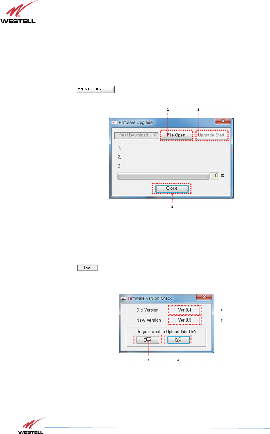
Firmware Upgrade progress window, Figure 7-1, displays.
Figure 7-1: Firmware Upgrade Progress Window File Open Tab
3. Click the File Open tab in the Firmware Upgrade progress window to display it, Figure
7-1.
4. Click to select the desired version file.
5.
Click in the Specify INI File to Open browser window, Figure 7-2. The Firmware
Version Check dialog window displays, Figure 7-2.
Figure 7-2: Firmware Version Check
PS71090-P8 Product Manual
October 2017, Rev A
WESTELL.COM
©2017 Westell Technologies October 2017; Doc No. CS14000802UM rA
1.877.844.4274 Page 46 of 51
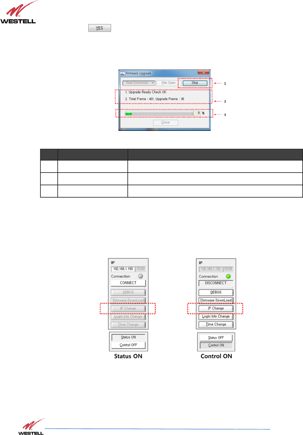
6. Click in the Firmware Version Check dialog window, Figure 7-3. The
firmware upgrade begins, as indicated by the progress bar in the Firmware
Version Check window, Figure 7-3.
Figure 7-3: Firmware Update Status
# Item Function
1 Stop Button to Stop Upgrade
2 Status Display real-time upgrade status
3 Progress Display Upgrade Progress
Note: You can stop the upgrade by pressing the Stop button.
7. When upgrade is completed, Firmware Upgrade Window is closed.
7.2
7.2 7.2
7.2 IP Change
IP ChangeIP Change
IP Change
Figure 7-4: IP Settings
1. With Control ON, the IP Change button is activated.
PS71090-P8 Product Manual
October 2017, Rev A
WESTELL.COM
©2017 Westell Technologies October 2017; Doc No. CS14000802UM rA
1.877.844.4274 Page 47 of 51
7.2.1 IP Change Window
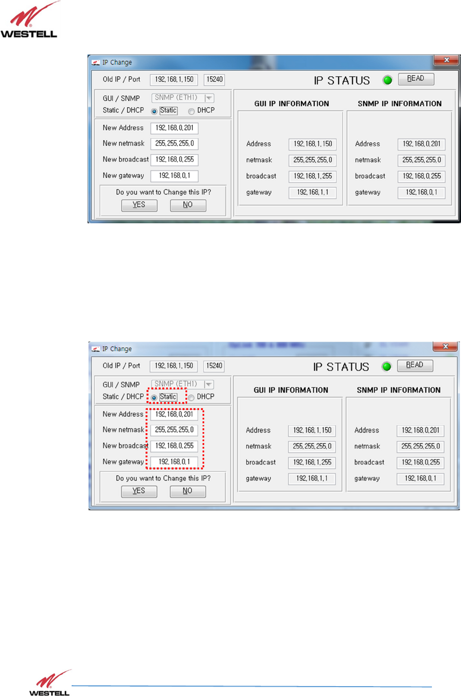
Figure 7-5: IP Change Window
1. Successful completion of IP Read, Status LED turns green and change icon is activated
2. When the IP Change Window is opened, the current status is displayed, Figure 7-10
a. Static IP can be set. (See 7.2.2)
b. DHCP IP can be set. (See 7.2.3)
7.2.2
7.2.2 7.2.2
7.2.2 Static IP
Static IPStatic IP
Static IP
S
SS
Setting
ettingetting
etting
Figure 7-6: Static IP Setting
1. Please write the Address / netmask / broadcast / gateway
2. If have all information set, please press YES button.
PS71090-P8 Product Manual
October 2017, Rev A
WESTELL.COM
©2017 Westell Technologies October 2017; Doc No. CS14000802UM rA
1.877.844.4274 Page 48 of 51
7.2.3
7.2.37.2.3
7.2.3
DHCP IP
DHCP IP DHCP IP
DHCP IP S
SS
Setting
ettingetting
etting
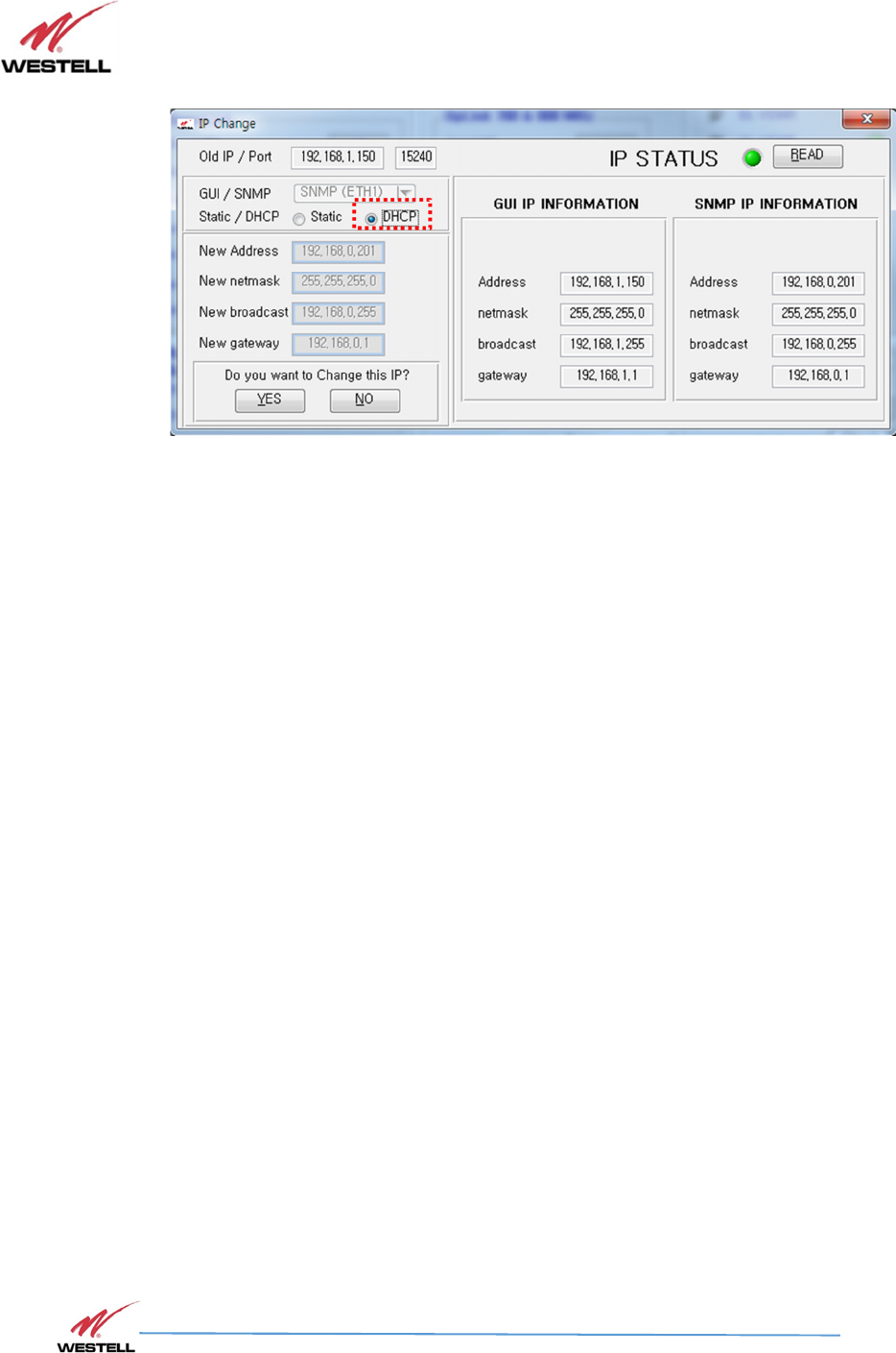
Figure 7-7: DHCP IP Setting
1. After DHCP select please click the YES button.

PS71090-P8 Product Manual
October 2017, Rev A
WESTELL.COM
©2017 Westell Technologies October 2017; Doc No. CS14000802UM rA
1.877.844.4274 Page 49 of 51
Appendix A Important Product Information
A.1 Registration Number
FCC – NVRPS71090-P8
A.2 UL
This product is UL Listed.
PS71090-P8 Product Manual
October 2017, Rev A
WESTELL.COM
©2017 Westell Technologies October 2017; Doc No. CS14000802UM rA
1.877.844.4274 Page 50 of 51
Appendix B Acronyms and Abbreviations
Table B-1 contains the acronyms and abbreviations used in this manual, along with a definition for
each one.
Table B-1: Acronyms and Abbreviations
Acronym/Abbreviation
Definition
AC
Alternating Current
AGC
Automatic Gain Control
COM
Communications
dB
Decibels
dBc
Decibels relative to the carrier
dBi
Decibels relative to isotropi
c
dBm
The power ratio in decibels (dB) of the measured
power referenced to one milliwatt (mW)
DC
Direct Current
DL
Downlink
FCC
Federal Communications Commission
HPA
High
-
Powered Amplifier
IF SAW
Intermediate Frequency Surface Acoustic Wa
ve
IP
Internet Protocol
LAN
Local Area Network
LED
Light Emitting Diode
MHz
Megahertz
NMS
Network Management System
OSC
Oscillator
PLL LD
Phase
-
locked loop with lock detection
RF
Radio Frequency
RS
-
232C
Serial Communication Stan
dard
UL
Uplink
UPS
Uninterruptable Power Supply
VAC
Volts Alternating Current (AC Voltage)
VSWR
Voltage Standing Wave Ratio
PS71090-P8 Product Manual
October 2017, Rev A
WESTELL.COM
©2017 Westell Technologies October 2017; Doc No. CS14000802UM rA
1.877.844.4274 Page 51 of 51
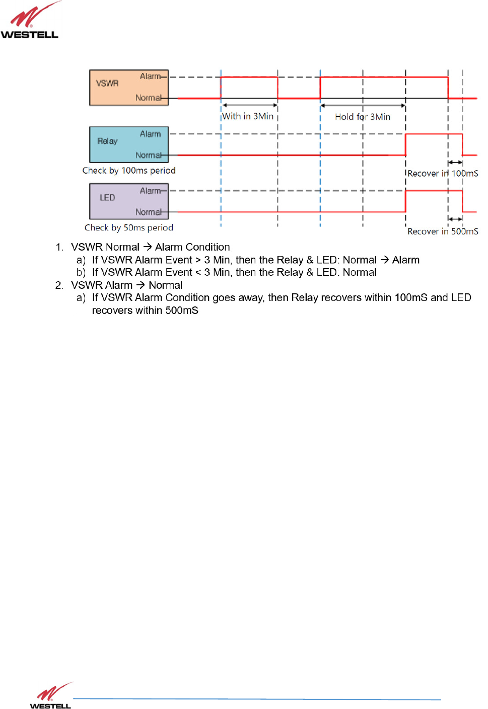
Appendix C Downlink & Uplink VSWR Alarm Timing Diagram