Western Auto 3455A89 User Manual REAR TINE TILLER Manuals And Guides 98080198
WESTERN AUTO Tiller Attachment Manual 98080198 WESTERN AUTO Tiller Attachment Owner's Manual, WESTERN AUTO Tiller Attachment installation guides
User Manual: Western Auto 3455A89 3455A89 WESTERN AUTO REAR TINE TILLER - Manuals and Guides View the owners manual for your WESTERN AUTO REAR TINE TILLER #3455A89. Home:Lawn & Garden Parts:Western Auto Parts:Western Auto REAR TINE TILLER Manual
Open the PDF directly: View PDF ![]() .
.
Page Count: 32
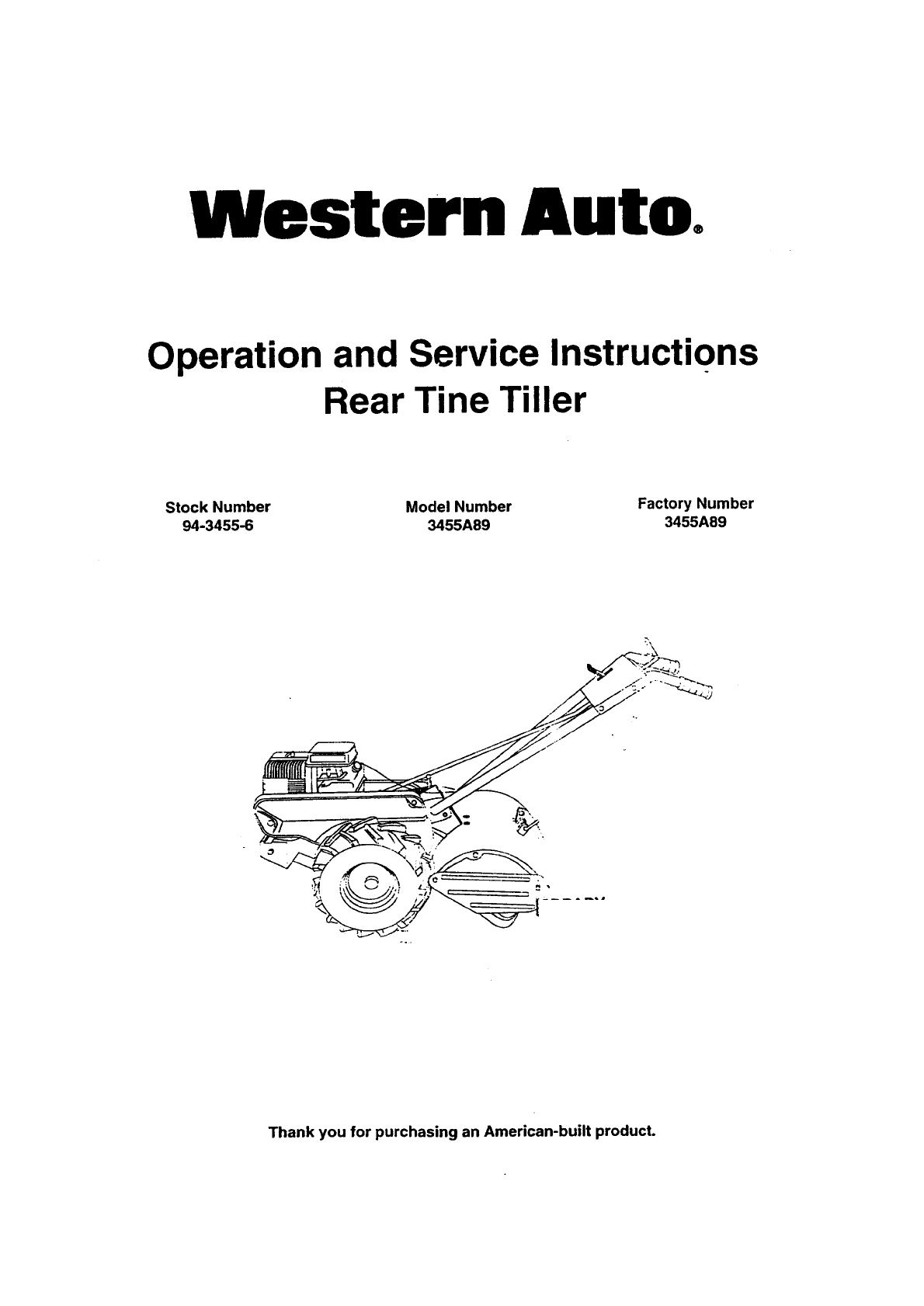
Western Auto°
Operation and Service Instructions
Rear Tine Tiller
Stock Number Model Number Factory Number
94-3455-6 3455A89 3455A89
J
Thank you for purchasing an American-built product.
ASAFETY RULES
Safe Operation Practices for Walk-Behind Powered Rotary Tillers A
TRAINING ....
•Read the O_f_er's Manual carefully. Be thoroughly
familiar with the controls and the proper use of the
equipment. Know how to stop the unit and disengage
the controls quickly.
•Never allow children to operate the equipment. Never
allow adults to operate the equipment without proper
instruction.
•Keep the area of operation clear of all persons, particu-
larly small children, and pets.
PREPARATION
•Thoroughly inspect the area where the equipment isto
be used and remove all foreign objects.
ET_engage all clutches and shift into neutral before
starting the engine (motor).
•Do not operate the equipment without wearing ad-
equate outer garments. Wear footwear that will im-
prove footing on slippery surfaces.
•Handle fuel with care; it is highly flammable.
•Use an approved fuel container.
•Never add fuel to a running engine or hot engine.
•Fillfuel tank outdoors withextreme care. Never fill fuel
tank indoors.
• Replace gasoline cap securely and clean up spilled
fuel before restarting.
• Use extension cords and receptacles as specified by
the manufacturer for all units with electric drive motors
or electric starting motors.
•Never attempt to make any adjustments while the
engine (motor) is running (except where specifically
recommended by manufacturer).
OPERATION
•Do not put hands or feet near or under rotating parts.
• Exercise extreme cautionwhen operating on or cross-
ing gravel drives, walks, or roads. Stay alert for hidden
hazards or traffic. Do not carry passengers.
•After striking a foreign object, stopthe engine (motor),
remove the wire from the spark plug, thoroughly in-
spect the tiller for any damage, and repair the damage
before restarting and operating the tiller.
•Exerc_e caution to avoid slipping or falling.
";_ If the unit should start t0 vibrate abnormally, stop the
engine (motor) and check immediately for the cause.
Vibration is generally a waming of trouble.
• Stop the engine (motor) when leaving the operating
position.
•Take all possible precautions when leaving the ma-
chine unattended. Disengage the tines, shift into
neutral, and stop t.heengine.
•Before cleaning, repairing, or inspecting, shut off the
engine and make certain allmovingpartshave stopped.
Disconnect the spark plug wire, and keep the wire
away from the plug to prevent accidental starting.
Disconnect the cord on electric motors.
•Do not run the engine indoors; exhaust fumes are
dangerous. ................
•Never operate the tiller without proper guards, plates,
or other safety protective devices in place.
• Keep children and pets away.
•Do notoverload the machine capacity by attemptingto ::_
till too deep at too fast a rate.
•Never operate the machine at highspeeds on slippery
surfaces. Look behind and use care when backing.
•Never allow bystanders near the unit.
•Use only attachments and accessories approved by
the manufacturer of the tiller (such as wheel weights,
counterweights, cabs, and the like).
•Never operate the tiller without good visibilityor light.
•Be careful when tilling in hard ground. The tines may
catch inthe groundand propel the tillerforward. If this
occurs, let goof the handlebars and do not restrain the
machine.
MAINTENANCE-AND STORAGE
• Keep machine, attachments, and accessories in safe
working condition.
•Check shear pins, engine mounting bolts, and other
bolts at frequent intervals for proper tightness to be
sure the equipment is in safe working condition.
•Never storethe machine withfuel inthe fueltank inside
a buildingwhere ignition sources are present, such as
hot water and space heaters, clothes dryers, and the
like. Allow the engine to cool before storing in any
enclosure.
• Always refer to the operator's guide instructions for
important details if the tiller is to be stored for an
extended period.
- IMPORTANT -
CAUTIONS, IMPORTANTS, AND NOTES ARE A MEANS
OF ATTRACTING ATTENTION TO IMPORTANT OR
CRITICAL INFORMATION IN THIS MANUAL.
IMPORTANT: USED TO ALERT YOU THAT THERE IS A
POSSIBILITY OF DAMAGING THIS EQUIPMENT.
NOTE: Gives essential information that will aid you to
better understand, incorporate, or execute a particular set
of instructions.
ALook for this symbol to point out im-
portant safety precautions. It means
CAUTIONlt! BECOME ALERTH! YOUR
SAFETY IS INVOLVED.
ACAUTION: Always disconnect spark
plug wire and place wire where it can-
not contact spark plug in order to pre-
vent accidental starting when setting
up, transporting, adjusting or making
r_pairs. _ -
AWARNING A
The engine exhaust from this product con-
tains chemicals known to the State of Califor-
nia to cause cancer, birth defects, or other
reproductive harm. I
2
._,Ul_i_Jirl/._ i ul,.._, i iul,i,_ ui iyvul Vu!_.,b ,a,_ ,... _, ,,.,,. u.,..,.. ,;.
has been designed, engineered and manufactured to gwe
you the best possible dependability and performance,
Should you exl_erie"w:_e:any proble_ _/ou cannot"easily
remedy, please contact your nearest authorized service
center, We have competent, well-trained technicians and
the proper tool_,'.toService or repair this unit.
Please read and retain this manual. The instructionswill
enable you to assemble and maintain your tiller properly.
Always observe the =SAFETY RULES'.
MODEL
NUMBER 3455A89
SERIAL
NUMBER
DATE OF PURCHASE
THE MODEL AND SERIAL NUMBERS WILL BE
FOUND ON THE MODEL PLATE ATTACHED TO
T-HE TOP OF THE TRANSMISSION.
YOU SHOULD RECORD BOTH SERIAL NUMBER
AND DATE OF PURCHASE AND KEEP IN ASAFE
PLACE FOR FUTURE REFERENCE.
rnuuuv i_}rr..igll-ii_n eiVl_h.)
HoRsEPOWER:'" -......5.5HP .................
DISPLACEMENT: 13 cu. in. (221cc)
GASOLINECAPACITY: 4Quads(__8L)
Unleaded Regular
OIL(API-SF/SG/SH): See "ENGINE" inCustomer
(CAPACITY:21 oz./0.6L) Responsibilities section
SPARK PLUG• Champion
(GAP: .030"/0.76mm) RN42C
CUSTOMER RESPONSIBILITIES
•Read and observe the safety rules.
•Follow a regularschedule in maintaining,caringfor and
using your tiller.
•Follow instructionsunder "Customer Responsibilities"
and "Storage" sections of this Owner's Manual.
IMPORTANT: THIS UNIT IS EQUIPPED WITH AN INTERNAL COMBUSTION ENGINE AND SHOULD NOT BE USED ON OR
NEAR ANY UNIMPROVED FOREST-COVERED, BRUSH-COVERED OR GRASS COVERED LAND UNLESS THE ENGINE'S
EXHAUST SYSTEM IS EQUIPPED WITH A SPARK ARRESTER MEETING APPLICABLE LOCAL LAWS (IF ANY). IF A
SPARK ARRESTER IS USED, IT SHOULD BE MAINTAINED IN EFFECTIVE WORKING ORDER BY THE OPERATOR.
IN THE STATE OF CALIFORNIA, A SPARK ARRESTER IS REQUIRED BY LAW (SECTION 4442 OF THE CALIFORNIA
PUBLIC RESOURCES CODE). OTHER STATES MAY HAVE SIMILAR LAWS. FEDERAL LAWS APPLY ON FEDERAL
LANDS. SEE YOUR AUTHORIZED SERVICE CENTER FOR SPARK ARRESTER.
WESTERN AUTO TILLER LIMITED WARRANTY
3455A89
Western Auto Supply Company warrants to the original retail purchaser that this product is free from defects in
material or workmanship and agrees to repair this product free of charge within these time periods from the date of
purchase:
• 2 years, if the product is used for personal, family, or householduse;
•90 days, if the productis used for any other purposesuch as commercialor rental use.
Excluded from thiswarranty are normalwear, maintenance, or mechanical ai:ljustmentswhichare notdue todefects
in material or workmanship. Consult your owner's manual for help to maintain your product or make mechanical
adjustments. Products which have been altered, misused, abused, or repaired by other than a Western Auto-authorized
or manufacturer-authorized service facility are also excluded.
A rideror tractor battery which proves defectivewithin90 days will be replacedwithoutcharge. After 90 days but
within-1year from the date of purchase, Western Auto will replace the battery for a charge of 1/12 of the currentretail price
of the battery for each full month between the date of purchase and the date of return.
Engines or transaxles are warranted by the engine or transaxle manufacturer whichgives its own 2year warranty
and provides service through its authorized service facilities. See the engine or transaxle warranty for details. Repair may
be arranged through participating Western Auto stores.
For repairservicereturn thisproduct withproofof purchase date to a participating Western Auto store. This warranty
gives youspecificlegal rightsand youmay have otherrightsthatvaryfromstateto state. If difficultyis encounteredinhaving
this warranty ho=_red, contact:
Western Auto Supply Company
Consumer AffairsSection of the General Service Department
2107 Grand Avenue, Kansas City, Missouri 64108
Telephone: 816 346-4411
3
TABLEOF CONTENTS
CUSTOMER RESp.ONSIBILmES ...................... 3,12-14
PRODUCT SPECIRCATIONS ...................................... 3
WARRANTY ............................. ;., ................................. 3
SAFETY RULES ............... ............................................. 2
ASSEMBLY ....;., ......................................................... 5-7
OPERATION ............................................................. 8-11
MAINTENANCE SCHEDULE .................................... 12
SERVICE & ADJUSTMENTS ................ ................. 15-17
STORAGE ................................................................... 18
TROUBLESHOOTING ................................................. 19
REPAIR PARTS-TILLER ........................................ 20-26
REPAIR PARTS-ENGINE ...................................... 27-31
INDEX
A
Adjustments:
-= De_th Stake .............................. 9
Handle Height ......................... 14
Side Shields............................ 10
Throttle ................................... 17
Tines ....................................... 16
V-Belt (Ground Drive) ............. 15
Air Cleaner .................................... 13
B
Belt:
Belt Guard .............................. 15
Repair Parts ............................ 21
V-Belt (Ground Drive) ............. 15
C
Cooling System ............................. 13
Controls:
Choke ....................................... 8
Throttle ..................................... 8
Tines (Drive Control) ................ 8
Cultivating ..................................... 11
Customer Responsibilities:
Air Cleaner .............................. 13
Cooling System ...................... 13
Finish ...................................... 14
Maintenance Schedule ........... 12
Muffler ..................................... 14
Oil Change .............................. 13
...... Spark Plug .............................. 14
_-Tmes ......-_-..:.................... ......... 16
Transmission .................... :..... 14
V-Belt (Ground Drive) ............. 15
D
Depth Stake:
Adjustment ....:'..:......................... 9
Repair Parts " 24
E
Engine:
Air Cleaner .............................. 13
Cooling System ...................... 13
Fuel Type ................................ 10
Engine (cont'd)
Lubrication .............................. 13
Oil Level .................................. 10
Oil Type ............................. 10,13
Spark Plug .............................. 14
Starling ................................... 11
Stopping ................................... 9
Storage ................................... 18
Winter Operation .................... 13
F
Fuel:
Filling Tank ............................. 10
Storage ................................... 18
Type ........................................ 10
Finish:
Maintenance ........................... 14
H
Handle:
Height Adjustment .................. 14
Repair Parts ............................ 20
L
Lubrication:
Lubrication Chart ................... 12
Engine .................................... 13
M
Muffler:
Maintenance ........................... 14
Spark Arrester .......................... 3
O
Oil: Level ....................................... 10
Type ................................... 10,13
Operation: ..
Cultivating ............................... 11
Fill Fuel Tank ........... ;..... ......... 10
Starting Engine ....................... 11
Stopping Tines & Engine .......... 9
Tilling ........................................ 9
Tilling Hints ............................. 11
Tine Operation .......................... 9
Transporting Tiller ................... 10
Winter Operation .................... 13
R
Repair Parts ............................. 20-31
Rules for Safe Operation ................. 2
S
Service & Adjustments:
Handle Height ......................... 14
Side Shields ............................ 10
Throttle ................................... 17
Tines ....................................... 16
V-Belt (Ground Drive) ............. 15
Wheels .................................... 14
Service:
Repair Parts ....................... 20-31
Service Record ....................... 12
Shear Pins:
Operation ................................ 11
Repair Parts ............................ 25
Spark Plug:
Gap ........................................... 3
Maintenance ........................... 14
Storage:
Fuel System ............................ 18
Tiller ........................................ 18
T
Tilling .......................................... 9,11
Tines:
Arrangement/Replacement ..... 16
Operation .................................. 9
Repair Parts ............................ 25
Shear Pins .............................. 11
Transmission:
Maintenance ........................... 14
Repair Parts ............................ 23
Troubleshooting ............................ 19
Transporting ........ .......................... 10
Wm
Warranty ...................... .-................... 3
Wheels:
Removal ........................... :..... 14
Repair Parts ............................ 22
4
ASSEMBLY!
Your new tiller has been assembled at the factory with exception of those parts left unassembled for shipping purposes. To
ensure safe and proper operation of yourtiller,all parts and hardware you assemble mustbe tightened securely. Use the
correct tools asl"iecessary to insure proper tightness.
TOOLS REQUIRED FOR ASSEMBLY
A socket wrench set will make assembly easier. Standard
wrench sizes are listed.
(1) Utility knife
(1) Tire pressure gauge
(1) Pair of pliers
(1) 9/16" wrench
(1) 7/16" wrench
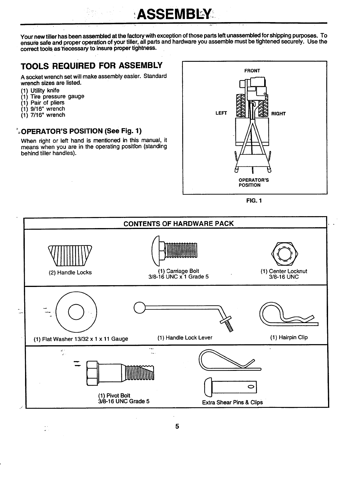
==OPERATOR'S POSITION (See Fig. 1)
When right or left hand is mentioned in this manual, it
means when you are in the operating positron (standing
behind tiller handles).
FRONT
LEFT RIGHT
I
OPERATOR'S
POSITION
FIG. 1
CONTENTS OF HARDWARE PACK
JIIlllll/Y
(2) Handle Locks (1) Carriage Bolt
3/8-16 UNC x1Grade 5
@
(1) Center Locknut
3/8-16 UNC
_j
(1) Flat Washer 13/32 x 1 x 11 Gauge
©
(1) PivotBolt
3/8-16 UNC Grade 5
(1) Handle Lock Lever
Extra Shear Pins & Clips
(1) HairpinClip
5
ASSEMBEY
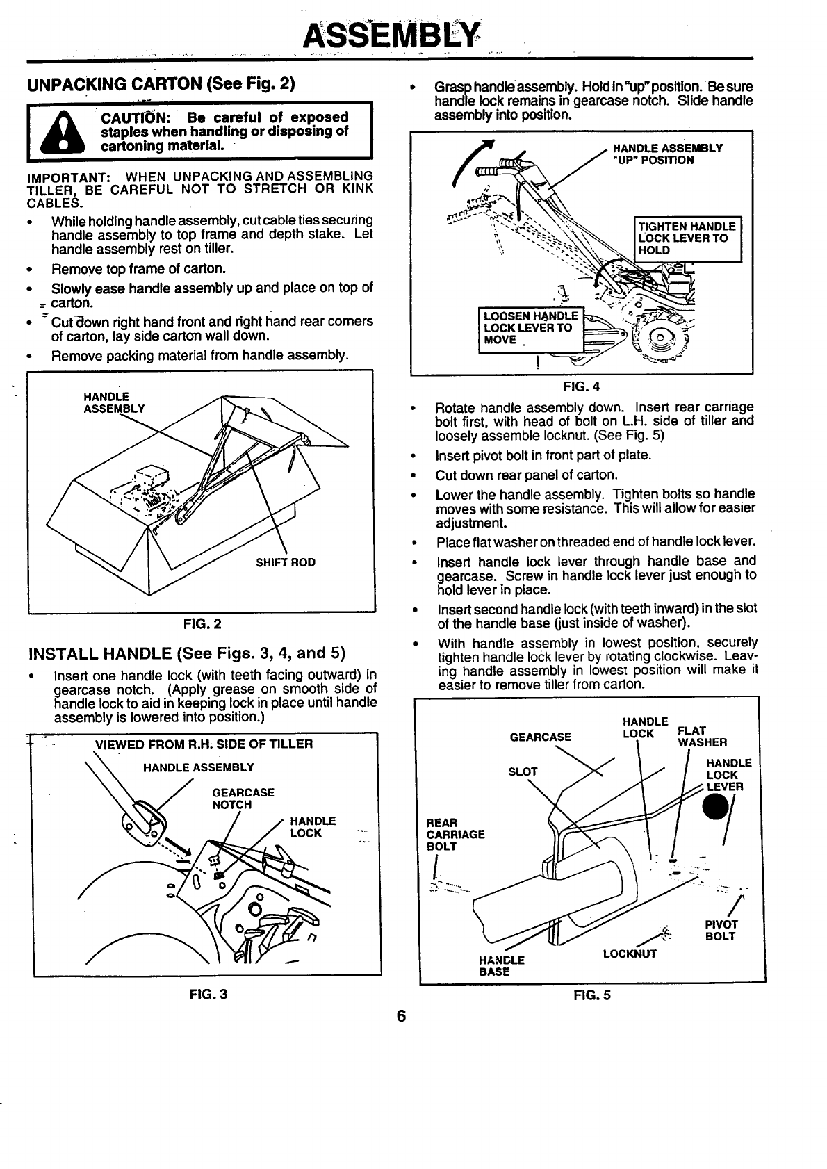
UNPACKING CARTON (See Fig. 2)
-it _
CAUTION: Be careful of exposed
staples when handling or disposing of
cartoning material.
IMPORTANT: WHEN UNPACKING AND ASSEMBLING
TILLER, BE CAREFUL NOT TO STRETCH OR KINK
CABLES.
• While holding handle assembly, cut cable ties securing
handle assembly to top frame and depth stake. Let
handle assembly rest on tiller.
• Remove top frame of carton.
• Slowly ease handle assembly up and place on top of
_-carton.
• = Cut-down right hand front and right I_and rear corners
of carton, lay side carton wall down.
•Remove packing material from handle assembly.
HANDLE
ASSEMBLY
SHIFT ROD
FIG. 2
INSTALL HANDLE (See Figs. 3, 4, and 5)
•Insert one handle lock (with teeth facing outward) in
gearcase notch. (Apply grease on smooth side of
handle lockto aid in keeping lock in place untilhandle
assembly is lowered into position.)
VIEWED FROM R.H; SIDE OF TILLER
HANDLE ASSEMBLY
GEARCASE
NOTCH
HANDLE
LOCK
Grasp handleassembly. Holdin=up"position.Be sure
handle lock remains in gearcase notch. Slide handle
assembly into position.
=.. HANDLE ASSEMBLY
"UP" POSITION
.... ILOCKLEVERTO
'_, "'-'"_-_.'X.'_., _. I HOLD
LOCK LEVER TO _'_'/_,'(._--_ -_-
MOVE ______________' _" ,_ o ..,._"_
FIG. 4
• Rotate handle assembly down. Insert rear carriage
bolt first, with head of bolt on L.H. side of tiller and
loosely assemble Iocknut. (See Fig. 5)
• Insert pivot bolt in front part of plate.
• Cut down rear panel of carton.
• Lower the handle assembly. Tighten bolts so handle
moves with some resistance. This will allow for easier
adjustment.
•Place flat washer on threaded end of handle lock lever.
• Insert handle lock lever through handle base and
gearcase. Screw in handle lock lever just enough to
hold lever in place.
• Insert second handle lock (with teeth inward) in the slot
of the handle base (just inside of washer).
• With handle assembly in lowest position, securely
tighten handle lock lever by rotating clockwise. Leav-
ing handle assembly in lowest position will make it
easier to remove tiller from carton.
HANDLE
GEARCASE LOCK FLAT
WASHER
SLOT
\
HANGLE
BASE
.o
LOCKNU'I"
HANDLE
LOCK
FIG. 3 FIG. 5
6
ASSEMBLY" -
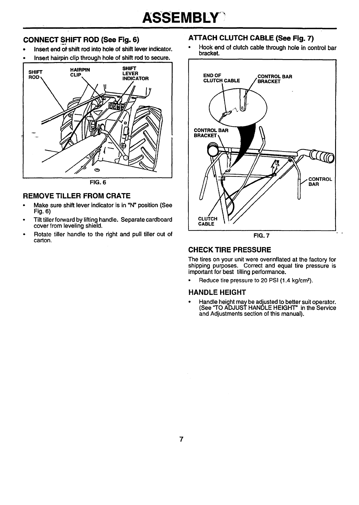
CONNECT SHIFT ROD (See Fig. 6)
•Insert end of shift rod into hole of shift lever indicator.
Insert hairpin clip through hole of shift rod to secure.
SHIFT HAIRPIN SHIFT
CLIP LEVER
INDICATOR
FIG. 6
REMOVE TILLER FROM CRATE
•Make sure shift lever indicator is in "N" position (See
Fig. 6)
•Tilt tillerforward by liftinghandle. Separate cardboard
cover from leveling shield,
•Rotate tiller handle to the right and pull tiller out of
carton.
ATi'ACH CLUTCH CABLE (See Fig. 7)
•Hook end of clutch cable through hole in control bar
bracket.
END OF CONTROLBAR
CLUTCH CABLE
CONTROLBAR
BRACKET
CONTROL
BAR
CLUTCH
CABLE
FIG. 7
CHECK TIRE PRESSURE
The tires on your unit were overinflated at the factory for
shipping purposes. Correct and equal tire pressure is
important for best tillingperformance.
•Reduce tire pre.ssure to 20 PSI (1,4 kg/cm2).
HANDLE HEIGHT
•Handle height may be adjusted to better suitoperator.
(See "TO ADJUST HANDLE HEIGHT" in the Service
and Adjustments section of this manual).
7
OPERATION.
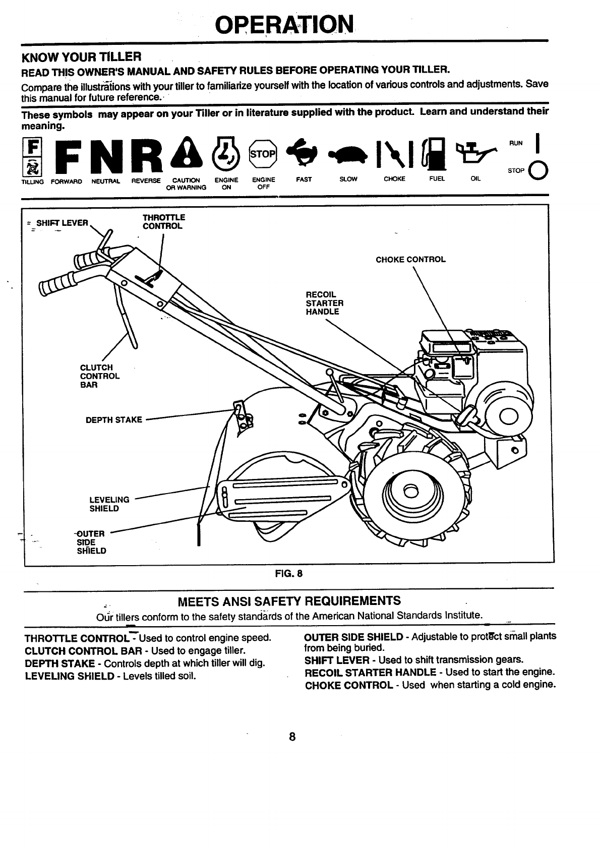
KNOW YOUR TILLER
READ TH!S OWNER'S MANUAL AND SAFETY RULES BEFORE OPERATING YOUR TILLER.
Compare the illust_{ions with your tiller to familiarize yourselfwith the location of various controls and adjustments. Save
this manual for future reference.
These symbols may appear on your Tiller or in literature supplied with the product. Learn and understand their
meaning.
TILUNG FORWARD NEUTRAL REVERSE CAUTION ENGINE ENGINE FAST SLOW CHOKE FUEL OIL
OR WARNING ON OFF
THROTTLE
=SHIFT LEVER CONTROL
CLUTCH
CONTROL
eAR
CHOKE CONTROL
RECOIL
STARTER
HANDLE
DEPTH STAKE
LEVELING
SHIELD
-OUTER
..... SIDE
S_ELD
FIG. 8
.MEETS ANSI SAFETY REQUIREMENTS
odr tillers conform to the safety standards of the American National Standards Institute.
THROTTLE CONTROL'-Used to control engine speed.
CLUTCH CONTROL BAR oUsed to engage tiller.
DEPTH STAKE -Controls depth at which tiller will dig.
LEVELING SHIELD -Levels tilled soil.
!
OUTER SIDE SHIELD -Adjustableto pmtL_ctsmall plants
from being buried.
SHIFT LEVER - Used to shift transmission gears.
RECOIL STARTER HANDLE - Used to start the engine.
CHOKE CONTROL - Used when starting a cold engine.
8
•...... .:,.,
:; OPERATION
The operation of any tiller can result in foreign objects thrown into the eyes, which can
result in severe eye damage. Always wear safety glasses or eye shields before starting
your tiller and while tilling. We recommend a wide vision safety mask over the spectacles
or standard safety glasses.
HOW TO USE YOUR TILLER
Know how to operate all controls before adding fuel and
oil or attempting to start engine.
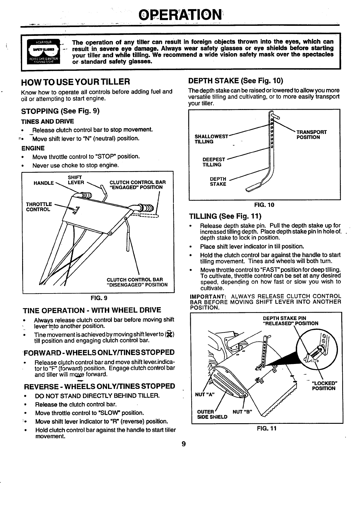
STOPPING (See Fig. 9)
TINES AND DRIVE
•Release clutch control bar to stop movement.
-"- -Move shiftlever to "N" (neutral) position.
ENGINE
• Move throttle control to "STOP" position.
•Never use choke to stop engine.
SHIFT
HANDLE LEVER CLUTCH CONTROL BAR
"ENGAGED" PosmoN/
CONTROL
CLUTCH CONTROL BAR
"DISENGAGED" POSITION
FIG. 9
TINE OPERATION -WITH WHEEL DRIVE
•Always release clutch control bar before moving shift
,lever-into another position.
•"Finemovement isachieved by moving shiftleverto (_)
till position and engaging clutch control bar.
FORWARD- WHEELS ONLY/rlNES STOPPED
• Release clutch control barand move shiftlever.indica-
torto "F" (forward) position. Engage clutch controlbar
and tiller will mo.y,.eforward.
REVERSE -WHE-ELS ONLY/TINES STOPPED
•DO NOT STAND DIRECTLY BEHIND TILLER.
• Release the clutch control bar.
•Move throttle control to "SLOW" position.
'• Move shilt lever indicator to "R" (reverse) position.
•Hold clutch control bar against the handle to start tiller
movement.
9
DEPTH STAKE (See Fig. 10)
The depth stakecan be raised or loweredto allow you more
versatile tilling and cultivating, or to more easily transport
your tiller.
SHALLOWES1
TILLING
DEEPEST I,,_ _
TILLING
DEPTH @
STAKE
POSITION
FIG. 10
TILLING (See Fig. 11)
•Release depth stake pin. Pull the depth stake up for
increasedtillingdepth. Place depth stake pin in hole of.
depth stake to lock in position.
•Place shift lever indicator intill position.
•Hold the clutch control bar against the handle to start
tillingmovement. Tines and wheels will both turn.
•Move throttlecontrol to ';FAST"positionfordeep tilling.
To cultivate, throttle control can be set at any desired
speed, depending on how fast or slow you wish to
cultivate.
IMPORTANT: ALWAYS RELEASE CLUTCH CONTROL
BAR BEFORE MOVING SHIFT LEVER INTO ANOTHER
POSITION.
DEPTH STAKE PIN
"RELEASED" POSITION
\
"LOCKED"
POSITION
NUT "B"
SIDE SHIELD
FIG. 11
OPERATION
t
TURNING
•Release the clutch control bar.
•Move throttle control to "SLOW" position.
•Place shift lever indicator in "F" (forward) position.
Tines will not turn.
Lift handle to raise tines out of groUnd.
Swing the handle in the opposite directionyou wish to
turn, being careful to keep feet and legs away from
tines.
• When you have completed your turn-around, release
the clutch control bar and lower handle. Place shift
lever intillposition and move throttle controlto desired
speed. To begin tilling, hold clutch control bar against
the handle.
(_-UTI_R SIDE SHIELDS (See Fig. 11)
The front edges of the outer side shieldsare slottedso that
the shields can be raised for deep tilling and lowered for
shallow tilling to protect small plants from being buried.
loosen nut "A"in slot and nut "B". Move shield to desired
position (both sides). Retighten nuts.
TO TRANSPORT
I
CAUTION: Before lifting or transport- I
ing, allow tiller engine and muffler to I
cool. Disconnect spark plug wire. Drain
gasoline from fuel tank.
AROUND THE YARD
• Release the depth stake pin. Move the depth stake
down to the top hole for transporting the tiller. Place
depth stake pin inhole of depth staketo lock inposition.
This prevents tines from scuffing the ground.
•Place shift lever indicator in "F" (forward) positionfor
transporting.
•Hold the drive control bar against the handle to start
tiller movement. Tines will not turn.
•Move throttle control to desired speed.
AROUND TOWN
•-- Disconnect spark plug wire.
•Drain fuet tank.
•Transport in upright position to prevent oil leakage.
BEFORE STARTING ENGINE
IMPORTANT: BE VERY CAREFUL NOT TO ALLOW DIRT
TO ENTER THE E:.NGINE WHEN CHECKING OR ADDING
OiL OR FUEL. USE CLEAN OIL AND FUEL AND STORE
IN APPROVED, CLEAN,_, COVERED CONTAINERS. USE
CLEAN FILL FUNNEL,R?/
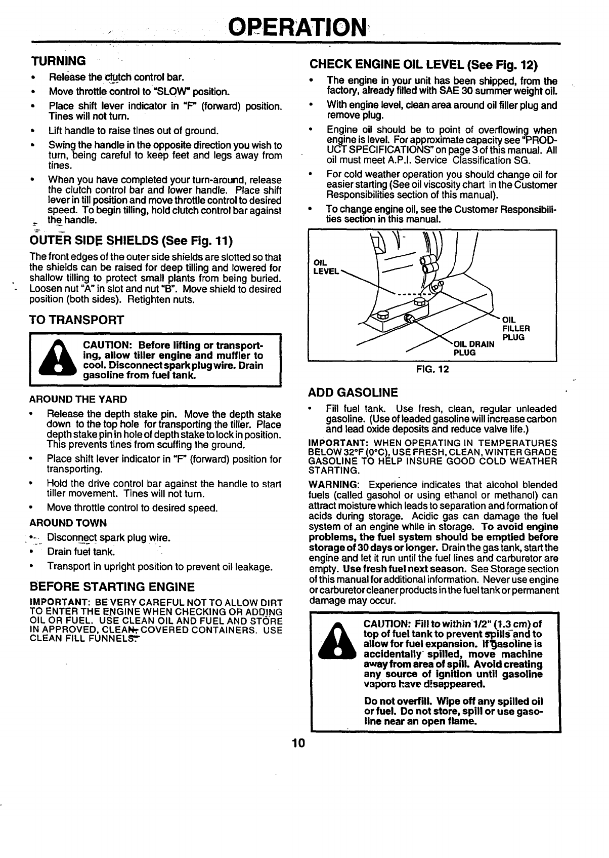
CHECK ENGINE OIL LEVEL (See Fig. 12)
•The engine in your unit has been shipped, from the
factory, already filledwith SAE 30 summer weight oil.
•With engine level, clean area around oil filler plug and
remove plug.
•Engine oil should be to point of overflowing when
engine is level. For approximate capacity see "PROD-
UCT SPECIFICATIONS" onpage 3 of this manual. All
oil must meet A.P.I. Service Classification SG.
•For cold weather operation you should change oil for
easier starting(See oil viscositychart inthe Customer
Responsibilitiessection of this manual).
•To change engine oil,see the Customer Responsibili-
ties section in this manual.
OIL
FILLER
PLUG
PLUG
FIG. 12
ADD GASOLINE
• Fill fuel tank. Use fresh, clean, regular unleaded
gasoline. (Use of leaded gasoline will increase carbon
and lead oxide deposits and reduce valve life.)
IMPORTANT: WHEN OPERATING IN TEMPERATURES
BELOW 32°F (0°C), USE FRESH, CLEAN, WINTER GRADE
GASOLINE TO HELP INSURE GOOD COLD WEATHER
STARTING.
WARNING: Experience indicates that alcohol blended
fuels (called gasohol or using ethanol or methanol) can
attract moisture which leads to separation and formation of
acids during storage. Acidic gas can damage the fuel
system of an engine while in storage. To avoid engine
problems, the fuel system should be emptied before
storage of 30 days or longer. Drainthe gas tank, startthe
engine and let it run untilthe fuel lines and carburetor are
empty. Use fresh fuel next season. See Storage section
of this manual foradditionalinformation. Never use engine
orcarburetorcleaner productsinthe fuel tank orpermanent
damage may occur.
i
CAUTION: Fill to within 1/2" (1.3 cm) of
top of fuel tank to prevent spills-and to
allow for fuel expansion. If_asoiine is
accidentally spilled, move machine
away from area of spill. Avoid creating
any source of ignition until gasoline
vapor_ h_ve d'.,sappeared.
Do not overfill. Wipe off any spilled oil
or fuel. Do not store, spill or use gaso-
line near an open flame.
10
IOPERATION
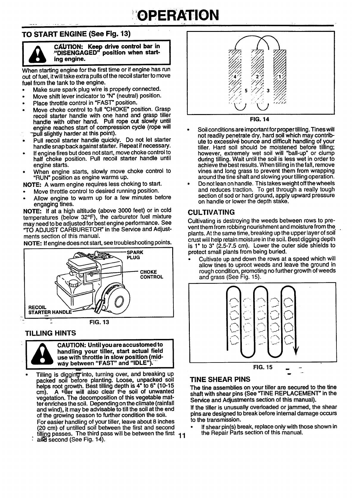
TO START ENGINE (See Fig. 13)
C_LJTION: Keep drive control bar in
"DISENGAGED', position when start-
ing engine.
When starting engine for the first time or if engine has run
out of fuel, itwilltake extra pullsofthe recoilstarterto move
fuel from the tank to the engine.
•Make sure spark plug wire is properlyconnected.
• Move shift lever indicator to "N"(neutral) position.
•Place throttle control in "FAST" position.
• Move choke control to full "CHOKE" position. Grasp
recoil starter handle with one hand and grasp tiller
handle with other hand. Pull rope out slowly until
engine reaches start of compression cycle (rope will
-pull slightly harder at this point).
Pull recoil starter handle quickly. Do not let starter
handle snap back against starter. Repeat ifnecessary.
•If engine fires but does notstart, move choke controlto
half choke position. Pull recoil starter handle until
engine starts.
• When engine starts, slowly move choke control to
"RUN" position as engine warms up.
NOTE: A warm engine requires less choking to start.
•Move throttle control to desired running position.
•Allow engine to warm up for afew minutes before
engaging tines.
NOTE: If at a high altitude (above 3000 feet) or in cold
temperatures (below 32°F), the carburetor fuel mixture
may need to be adjustedfor best engine performance. See
"TO ADJUST CARBURETOR" in the Service and Adjust-
ments section of this manual.
NOTE: Ifengine does notstart, see troubleshootingpoints.
SPARK
GCHOK E
CONTROL
RECOIL "X_---"_T_..---_-_J2_/ _i
STARTE_R HANDLE""'-- _f./'_'_...__
- FIG. 13
TILLING HINTS
I_CAUTION: Until you are accustomed to
handling your tiller, start actual field
use with throttle in slow position (mid-
way between "FAST" and "IDLE").
•Tilling is diggin_J"into,turning over, and breaking up
packed soil before planting. Loose, unpacked soil
helps root growth. Best tilling depth is 4" to 6• (10-15
cm). A tiller will also clear the soil of unwanted
vegetation. The decomposition of this vegetable mat-
ter enriches the soil. Depending on the climate (rainfall
and wind), it may be advisable to till the soil at the end
of the growing season to further conditionthe soil.
For easier handling of your tiller, leave about 8 inches
(20 cm) of untilled soil between the first and second
tilling passes. The third pass will be between the first 11
•a_ second (See Fig. 14).
i':: :--i/77yJ..::
'tLDS"t;,LJ "'""
FIG. 14
•Soilconditionsare important forproper tilling.Tines will
not readily penetrate dry, hard soil which may contrib-
ute to excessive bounce and difficulthandling of your
tiller. Hard soil should be moistened before tilling;
however, extremely wet soil will "ball-up" or clump
during tilling.Wait untilthe soil is less wet in order to
achieve the best results.When tillingin the fall, remove
vines and long grass to prevent them from wrapping
around the tine shaftand slowing your tilling operation.
• Do not lean on handle. This takes weight off the wheels
and reduces traction. To get through a really tough
section of sod or hard ground, apply upward pressure
on handle or lower the depth stake.
CULTIVATING
Cultivating is destroying the weeds between rows to pre-
vent them from robbing nourishment and moisture from the.
plants. At the same time, breaking up the upper layer of soil
crust will help retain moisture in the soil. Best digging depth
is 1" to 3" (2.5-7.5 cm). Lower the outer side shields to
protect small plants from being buried.
•Cultivate up and down the rows at a speed which will
allow tines to uproot weeds and leave the ground in
rough condition, promoting no further growth of weeds
and grass (See Fig. 15).
r_-..I
,I_.1
\..1
t2
k.--P
FIG. 15 _ -
TINE SHEAR PINS
The tine assemblies on your tiller are secured to the tine
shaft with shear pins (See "I'INE REPLACEMENT" inthe
Service and Adjustments section of this manual).
If the tiller is unusually overloaded or jammed, the shear
pins are designed to break before internal damage occurs
to the transmission.
•If shear pin(s) break, replace only with those shown in
the Repair Parts section of this manual.
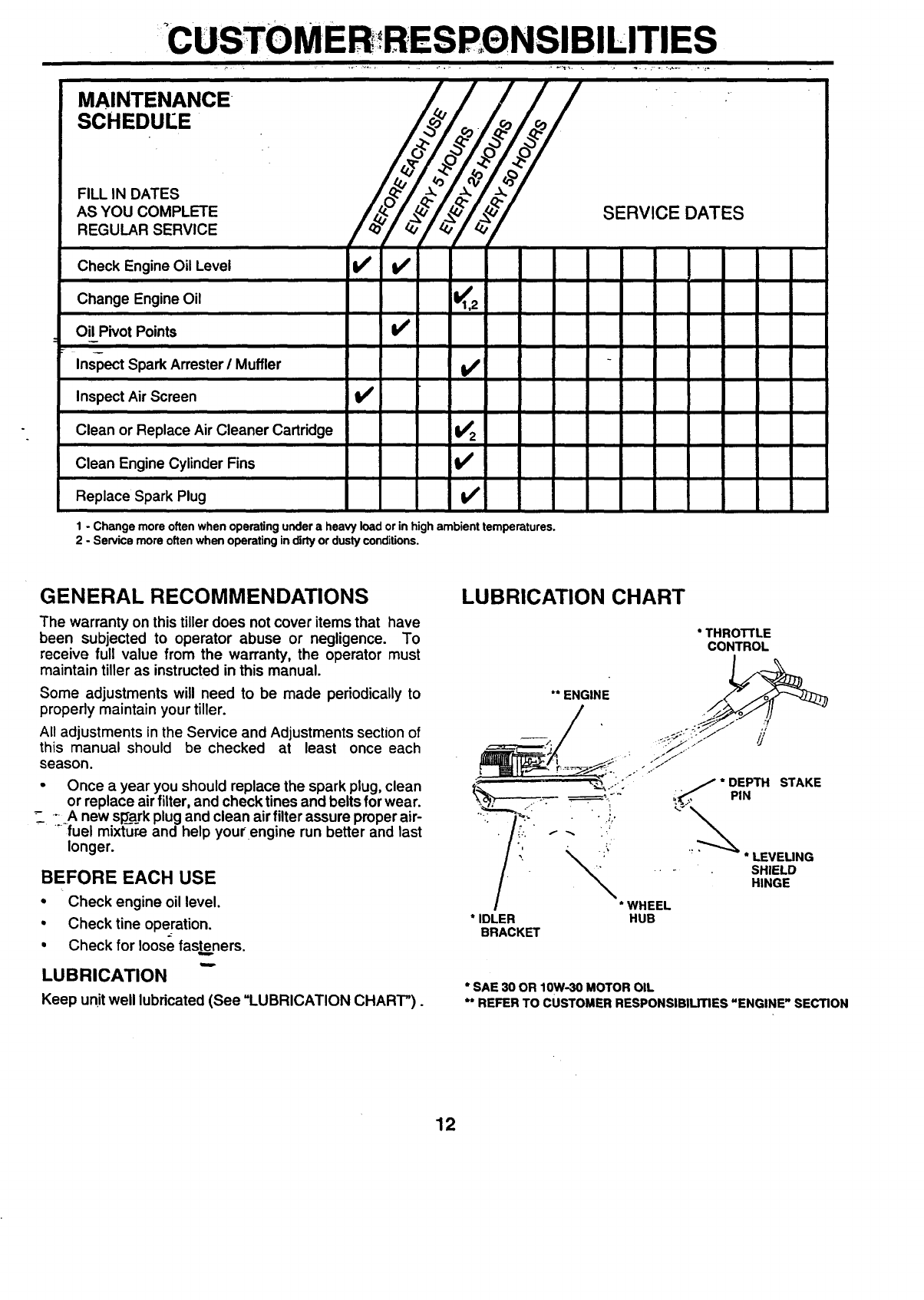
•CUSTOMER RESP, eNSIBILITIES
i
MAINTENANCE
SCHEDUEE
FILL IN DATES
AS YOU COMPLETE
REGULAR SERVICE Xo -7.jy.,
Check Engine Oil Level V' I_
i
Change Engine Oil K2
Oil Pivot Points
Inspect Spark Arrester/Muffler
Inspect Air Screen II_
Clean or Replace Air Cleaner Cartridge I/2
Clean Engine Cylinder Fins
Replace Spark Plug I#t
SERVICE DATES
1-Change more often when operating under a heavy load orin highambient temperatures.
2 - Service more often when operating in dirty or dusty conditions.
GENERAL RECOMMENDATIONS
The warranty on this tiller does not cover items that have
been subjected to operator abuse or negligence. To
receive full value from the warranty, the operator must
maintain tiller as instructed in this manual.
Some adjustments will need to be made periodically to
properly maintain your tiller.
All adjustments in the Service and Adjustments section of
this manual should be checked at least once each
season.
•Once a year you should replace the spark plug, clean
or replace airfilter, and check tines and belts for wear.
.... A new sp_a_rkplugand clean air filter assure proper air-
- "-fuel mixture and help your engine run better and last
longer.
BEFORE EACH USE
•Check engine oil level.
•Check tine operation.
• Check for loose fasteners.
LUBRICATION
Keep unit well lubricated (See =LUBRICATION CHART").
LUBRICATION CHART
* THROTTLE
CONTROL
** ENGINE
* SAE 30 OR 10W-30 MOTOR OIL
** REFER TO CUSTOMER RESPONSIBILITIES "ENGINE" SECTION
12
CUSTOME RESBQNSIBIEITIES
Disconnect spark plug wire before performing any maintenance (except carburetor adjustment) to prevent
accidental starting of engine.
Prevent fire!! Keep the engine free of grass, leaves, spilled oil, or fuel. Remove fuel from tank before tipping unit
for maintenance. Clean muffler area of all grass, dirt, end debris.
Do not touch hot muffler or cylinder fins as contact may cause bums.
ENGINE
LUBRICATION
Use only high quality detergent oil rated with API servica
classification SF, SG or SH. Select the oil's SAE viscosity
grade according to your expected temperature.
SAE VISCOSITY GRADES
I
°F -20" O" 30' 32* 40" 60 =80 =100 =
°C -30" -20" -10" 0=10" 20" 30" 40 =
TEMPERATURE RANGE ANTICIPATED BEFORE NEXT OIL CHANGE
FIG. 16
NOTE: Although multi-viscosity oils (5W-30,10W-30, etc.)
improve starting in cold weather, these multi-viscosityoils
will result in increased oil consumption when used above
32°F (0°C). Check your engine oil level more frequently to
avoid possible engine damage from running low on oil.
Change the oil after every 25 hours of operation or at least
once a year ifthe tractor is not usedfor25 hoursinone year.
Check the crankcase oil level before starting the engine
and after each five (5) hours of continuous use. Add SAE
30 motor oil or equivalent. Tighten oil filler plug securely
each time you check the oil level.
TO CHANGE ENGINE OIL (See Figs. 16 and 17)
Determine temperature range expected before oilchange.
All oil must meet API service classificationSF, SG or SH.
• Be sure tiller is on level surface.
•Oil will drain more freely when warm.
•Use afunnel to prevent spillon tiller, and catch oil ina
suitable container.
•Remove drain plug.
•Tip tiller forward to drain oil.
• After oil has drained completely, replace oil drain plug
-_ and _.qhten securely.
_, Remove oil filler plug. Be careful not to allow dirt to
enter the engine.
•Refill engine with oil. See "CHECK ENGINE OIL
LEVEL" in the Operation section of this manual.
OIL
DRAIN
OIL FILLER
PLUG
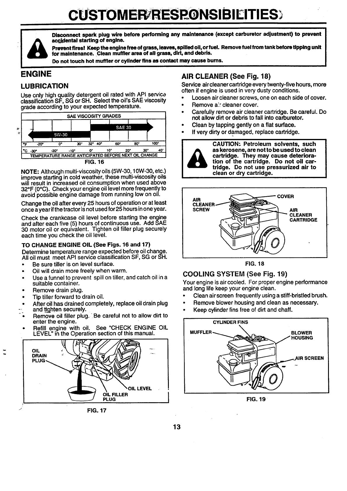
AIR CLEANER (See Fig. 18)
Service aircleaner cartridge every twenty-five hours, more
often if engine is used in very dusty conditions.
• Loosen air cleaner screws, one on each side of cover.
• Remove ai."cleaner cover.
•Carefully remove air cleaner cartridge. Be careful. Do
not allow dirt or debris to fall into carburetor.
•Clean by tapping gently on a flat surface.
•If very dirty or damaged, replace cartridge.
CAUTION- Petroleum solvents, such
as kerosene, are not to be used to clean
cartridge. They may cause deteriora-
tion of the cartridge. Do not oil car-
tridge. Do not use pressurized air to
clean or dry cartridge.
AIR COVER
AIR
CLEANER
CARTRIDGE
?
FIG. 18
COOLING SYSTEM (See Fig. 19)
Your engine is air cooled. For proper engine performance
and long life keep your engine clean.
•Clean air screen frequently usinga stiff-bristledbrush.
•Remove blower housingand clean as necessary.
•Keep cylinder fins free of dirt and chaff.
CYUNDER FINS
BLOWER
HOUSING
FIG. 19
FIG. 17
13

°
GUSTOMER RESPONSIBIE, ITIES
MUFFLER ' .... .....................
Do not operate tiller without muffler. Do not tamper with
exhaust system. Damaged mufflers or spark an'esters
couldcreate a fire hazard. Inspect pedodically and replace
if necessary. If your engine is-equipped with a spark
attester screen assembly, remove every 50 hours for
cleaning and inspection. Replace if damaged.
SPARK PLUG
Replace sparkplugs at the beginningof each tillingseason
orafterevery50 hoursof use, whichever comesfirst. Spark
plugtype and gap setting is shown in =PRODUCT SPECI-
FICATIONS" on page 3 of this manual.
TRANSMISSION .....
Your transmissionissealed and willonly require lubrication
if serviced.
CLEANING
•Clean engine, wheels, finish,etc. of all foreign matter.
• Keep finished surfaces and wheels free of all gasoline,
oil, etc.
• Protect painted surfaces with automotive type wax.
We do not recommend using a garden hose to clean your
unit unless the muffler, air filter and carburetor are covered
to keep water out. Water in engine can result in a shortened
engine life.
i
: -_ SERVICE AND ADJUSTMENTS
i i
i
&CAUTION: Disconnect spark plug wire from spark plug and place wire where it cannot come into
contact with plug.
TILLER
TO ADJUST HANDLE HEIGHT (See Fig. 20)
Select handle height best suited for your ti!lingconditions.
Handle height will be different when tiller digs into soil.
•First loosen handle lock lever.
•Handle can be positioned at differentsettings between
"HIGH" and "LOW" positions.
•Retighten handle lock lever securely after adjusting.
HANDLE (HIGH
POSITION)
HANDLE LOCK
LEVER
"i- HANDLE (l:.-OW
POSITION) -
,FIG. 20 --
TIRE CARE ---
I& CAUTION: When mounting tires, un-
less beads are seated, overinflation
can cause an explosion.
i
•Maintain 20 PSI (1.4 kg/cm =) of tire pressure. If tire
pressures are not equal, tiller will pull to one sloe.
•Keep tires free of gasoline or oil which can damage
rubber.
TO REMOVE WHEEL (See Fig. 21)
•Place blocks under transmission to keep tiller from
tipping.
•Remove outersideshieldby removing nuts"A" and"B".
•Remove inner side shield by .removing nuts "C" and
M[_M.
•Remove hairpin clip and clevis pin from wheel.
• Remove wheel and tire.
•Repair tire and reassemble.
CLEVIS
HAIRPIN
CLIP
NUT "A"
OUTER
SIDE
SHIELD
_IER SIDE
SHIELD
FIG. 21
14
SERVICEAN D ADJUSTM ENTS
i
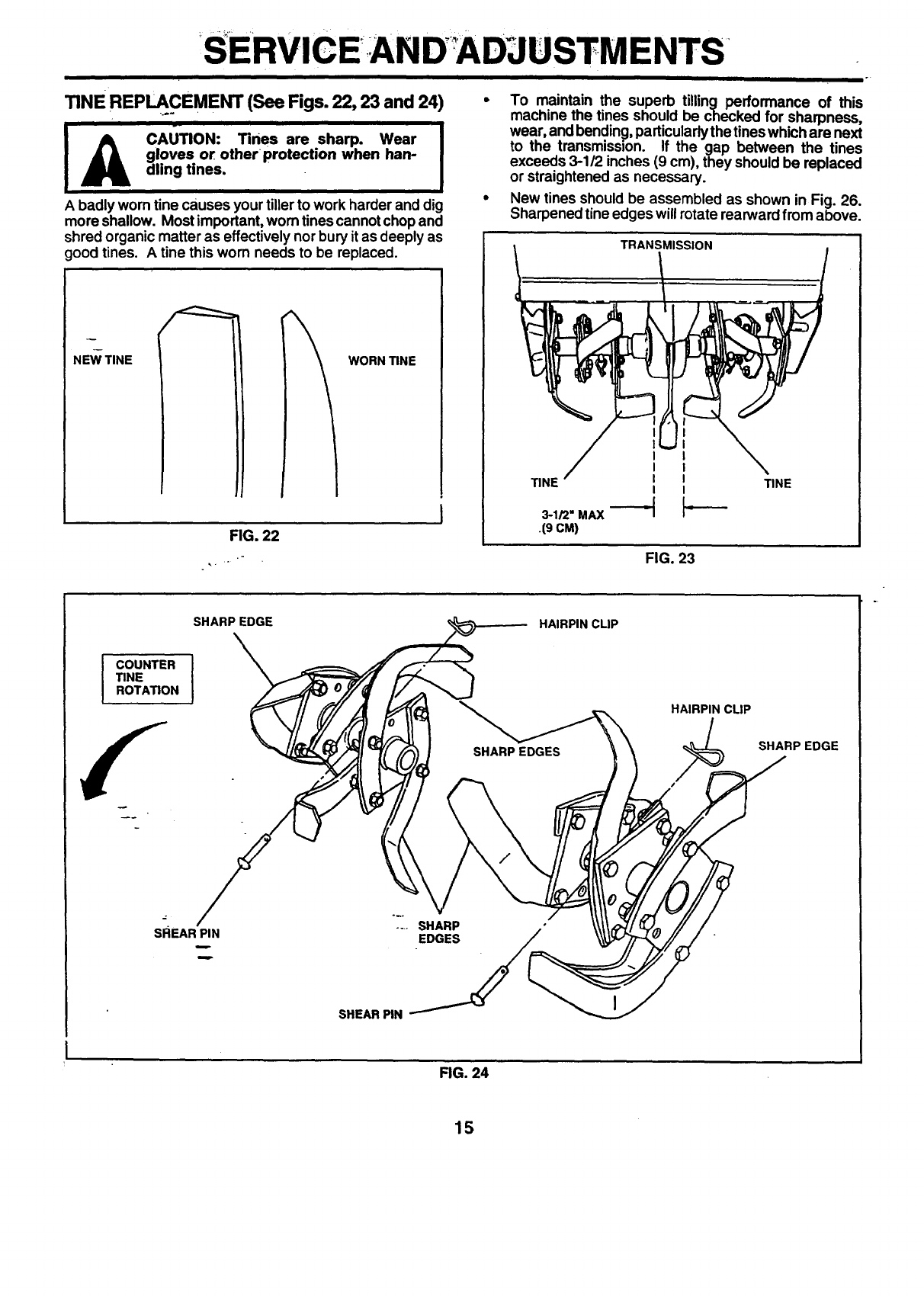
TINE REPLy. CEMENT (See Figs. 22, 23 and 24)
i _-
_CAUTION: Tines are sharp. Wear
gloves or other protection when han-
dling tines.
A badly worn tine causes your tiller to work harder and dig
more shallow. Most important,worn tinescannot chop and
shred organic matter as effectively nor bury it as deeply as
good tines. A tine this worn needs to be replaced.
WORN "lINE
FIG. 22
TRANSMISSION
To maintain the superb tilling performance of this
machine the tines should be checked for sharpness,
wear, and bending, particularlythe tineswhich are next
to the transmissson. If the gap between the tines
exceeds 3-1/2 inches (9 cm), they should be replaced
or straightened as necessary.
New tines should be assembled as shown in Fig. 26.
Sharpened tine edges will rotate rearward from above.
II
I I
TINE I I
I I
.19CM)
TINE
FIG. 23
IOUNTER
TINE
ROTATION
SHARP EDGE
I
HAIRPIN CLIP
SHARP EDGES
HAIRPIN CLIP
SHARPEDGE
SREAR PIN .... SHARP ."
SHEAR PIN _
FIG. 24
15
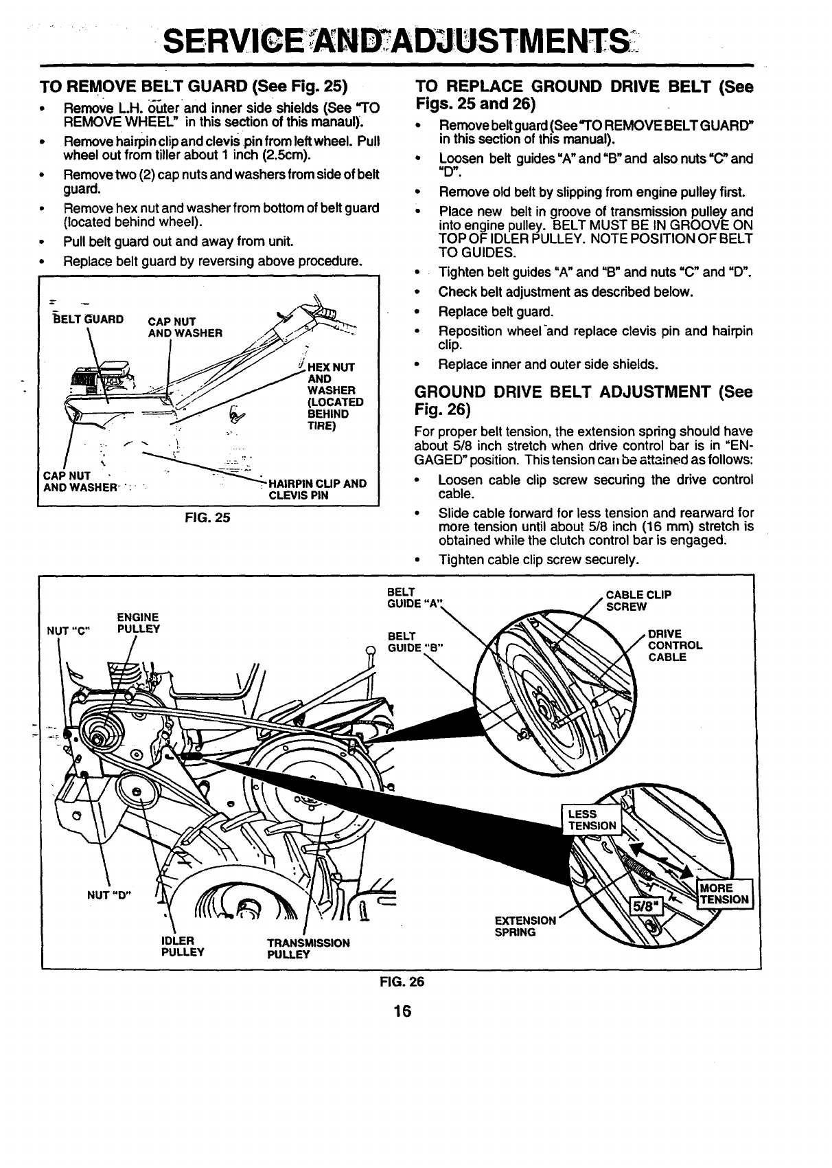
TO REMOVE BELT GUARD (See Fig. 25)
•Remove L.H. outer and inner side shields (See "TO
REMOVE WHEEL" in this section of this manaul).
•Remove hairpinclip and clevispin from leftwheel. Pull
wheel out from tiller about I inch (2.5cm).
•Remove two (2) cap nuts and washers from sideof belt
guard.
•Remove hex nut andwasher from bottomof belt guard
(located behind wheel).
•Pull belt guard out and away from unit.
•Replace belt guard by reversing above procedure.
_ELT_UARD
CAPNUT
AND WASHER'':-
CAP NUT
AND WASHER
d' HEX NUT
AND
WASHER
(LOCATED
BEHIND
_. TIRE)
_HAIRPIN CUP AND
CLEVIS PIN
FIG. 25
TO REPLACE GROUND DRIVE BELT (See
Figs. 25 and 26)
• Remove beltguard(See'TO REMOVE BELT GUARD"
in this section of this manual).
• Loosen belt guides"A"and"B" and also nuts=C"and
"D".
•Remove old belt by slipping from engine pulley first.
• Place new belt in groove of transmission pulley and
into engine pulley. BELT MUST BE IN GROOVE ON
TOP OF IDLER PULLEY. NOTE POSITION OF BELT
TO GUIDES.
• Tighten belt guides "A"and "B" and nuts "C" and "D".
•Check belt adjustment as described below.
•Replace belt guard.
•Reposition wheeland replace clevis pin and hairpin
clip.
•Replace inner and outer side shields.
GROUND DRIVE BELT ADJUSTMENT (See
Fig. 26)
For proper belt tension, the extension spring should have
about 5/8 inch stretch when drive control bar is in "EN-
GAGED" position. This tensionca. be a_ained as follows:
•Loosen cable clip screw securing the drive control
cable.
•Slide cable forward for less tension and rearward for
more tension until about 5/8 inch (16 mm) stretch is
obtained while the clutch control bar is engaged.
• Tighten cable clip screw securely.
ENGINE
NUT "C" PULLEY
BELT
GUIDE
BELT
GUIDE "B"
CABLE CLIP
SCREW
DRIVE
CONTROL
CABLE
LESS
TENSION
IDLER
PULLEY TRANSMISSION
PULLEY
EXTENSION
SPRING
FIG. 26
16
....SERVICE AND ADJUSTMENTS
ENGINE
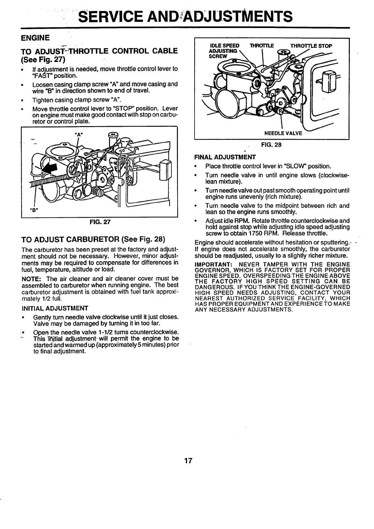
TO ADJuST-.THROTFLE CONTROL CABLE
(See Fig, 27)
•If adjustment is needed, move throttlecontrol lever to
=FAST" position.
•Loosen casing clamp screw "A"and move casing and
wire "B"in direction shown to end of travel.
Tighten casing clamp screw "A".
Move throttle control lever to "STOP" position. Lever
on engine must make goodcontact with stoponcarbu-
retor or control plate.
"B"
FIG. 27
TO ADJUST CARBURETOR (See Fig. 28)
The carburetor has been preset at the factory and adjust-
ment should not be necessary. However, minor adjust-
ments may be required to compensate for differences in
fuel, temperature, altitude or load.
NOTE: The air cleaner and air cleaner cover must be
assembled to carburetor when running engine. The best
carburetor adjustment is obtained with fuel tank approxi-
mately 1/2 full.
INITIAL ADJUSTMENT
•Gently turn needle valve clockwise until it just closes.
Valve may be damaged by turning it in too far.
,o Open the needle valve 1-1/2 tums counterclockwise.
-This T_jtial adjustment-will permit the engine to be
started andwarmed up (approximately 5 minutes) prior
to final adjustment.
IDLE SPEED THROTTLE
SCREW
THROTTLE STOP
NEEDLE VALVE
FIG. 28
FINAL ADJUSTMENT
•Place throttlecontrol lever in =SLOW" position.
•Turn needle valve in until engine slows (clockwise-
lean mixture).
•Turn needle valve outpast smoothoperating pointuntil
engine runs unevenly (rich mixture).
•Turn needle valve to the midpoint between rich and
lean so the engine runs smoothly.
•Adjust idle RPM. Rotate throttlecounterclockwise and
hold against stopwhile adjusting idle speed adjusting
screw to obtain 1750 RPM. Release throttle.
Engine should accelerate without hesitation or sputtering..
If engine does not accelerate smoothly, the carburetor
should be readjusted, usually to a slightly richer mixture.
IMPORTANT" NEVER TAMPER WITH THE ENGINE
GOVERNOR, WHICH IS FACTORY SET FOR PROPER
ENGINE SPEED. OVERSPEEDING THE ENGINE ABOVE
THE FACTORY HIGH SPEED SETTING CAN BE
DANGEROUS. IF YOU THINK THE ENGINE-GOVERNED
HIGH SPEED NEEDS ADJUSTING, CONTACT YOUR
NEAREST AUTHORIZED SERVICE FACILITY, WHICH
HAS PROPER EQUIPMENT AND EXPERIENCE TO MAKE
ANY NECESSARY ADJUSTMENTS.
17
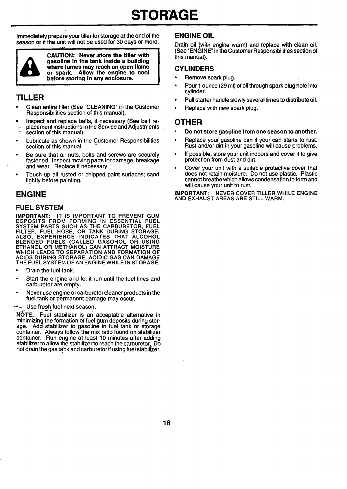
STORAGE
Immediately prepare your tillerfor storage at the end of the
season or if the unit will not be used for 30 days or more.
cAuTION: Never store the tiller with
gasoline in the tank inside a building
where fumes may reach an open flame
or spark. Allow the engine to cool
before storing in any enclosure.
TILLER
• Clean entire tiller (See "CLEANING" in the Customer
Responsibilities section of this manual).
•Inspect and replace belts, if necessary (See belt re-
= =placement instructionsinthe Service and Adjustments
-- section of this manual),
•Lubricate as shown in the Customer Responsibilities
section of this manual.
•Be sure that all nuts, bolts and screws are securely
fastened. Inspect moving parts fordamage, breakage
and wear. Replace if necessary.
•Touch up all rusted or chipped paint surfaces; sand
lightly before painting.
ENGINE
FUEL SYSTEM
IMPORTANT: IT IS IMPORTANT TO PREVENT GUM
DEPOSITS FROM FORMING IN ESSENTIAL FUEL
SYSTEM PARTS SUCH AS THE CARBURETOR, FUEL
FILTER, FUEL HOSE, OR TANK DURING STORAGE.
ALSO, EXPERIENCE INDICATES THAT ALCOHOL
BLENDED FUELS (CALLED GASOHOL OR USING
ETHANOL OR METHANOL) CAN ATTRACT MOISTURE
WHICH LEADS TO SEPARATION AND FORMATION OF
ACIDS DURING STORAGE. ACIDIC GAS CAN DAMAGE
THE FUEL SYSTEM OF AN ENGINE WHILE IN STORAGE.
•Drain the fuel tank.
• Start the engine and let it run until the fuel lines and
carburetor are empty.
•Never use engine or carburetor cleaner products inthe
fuel tank or permanent damage may occur.
•Use fresh fuel next season.
N-I_TE: Fuel stabilizer is an acceptable alternative in
minimizing the formation of fuel gum deposits during stor-
age. Add stabilizer to gasoline in fuel tank or storage
container. Always follow the mix ratio found on stabilizer
container. Run engine at least 10 minutes after adding
stabilizer to allow the stabilizer to reach the carburetor. Do
notdrain the gas t_nk and carburetor if usingfuel stabilizer.
ENGINE OIL
Drain oil (with engine warm) and replace with clean oil.
(See "ENGINE" inthe Customer Responsibilitiessectionof
this manual).
CYLINDERS
•Remove spark plug.
•Pour I ounce (29 ml) of oil throughspark plughole into
cylinder.
•Pullstarter handle slowlyseveral times to distributeoil.
•Replace with new spark plug.
OTHER
•Do not store gasoline from one season to another.
•Replace your gasoline can if your can starts to rust.
Rust and/or dirt in your gasoline will cause problems.
•If possible, store your unit indoors and cover itto give
protection from dust and dirt.
•Cover your unit with a Suitable protective cover that
does not retain moisture. Do not use plastic. Plastic
cannot breathe which allows condensation to form and
will cause your unit to rust.
IMPORTANT: NEVER COVER TILLER WHILE ENGINE
AND EXHAUST AREAS ARE STILL WARM.
18
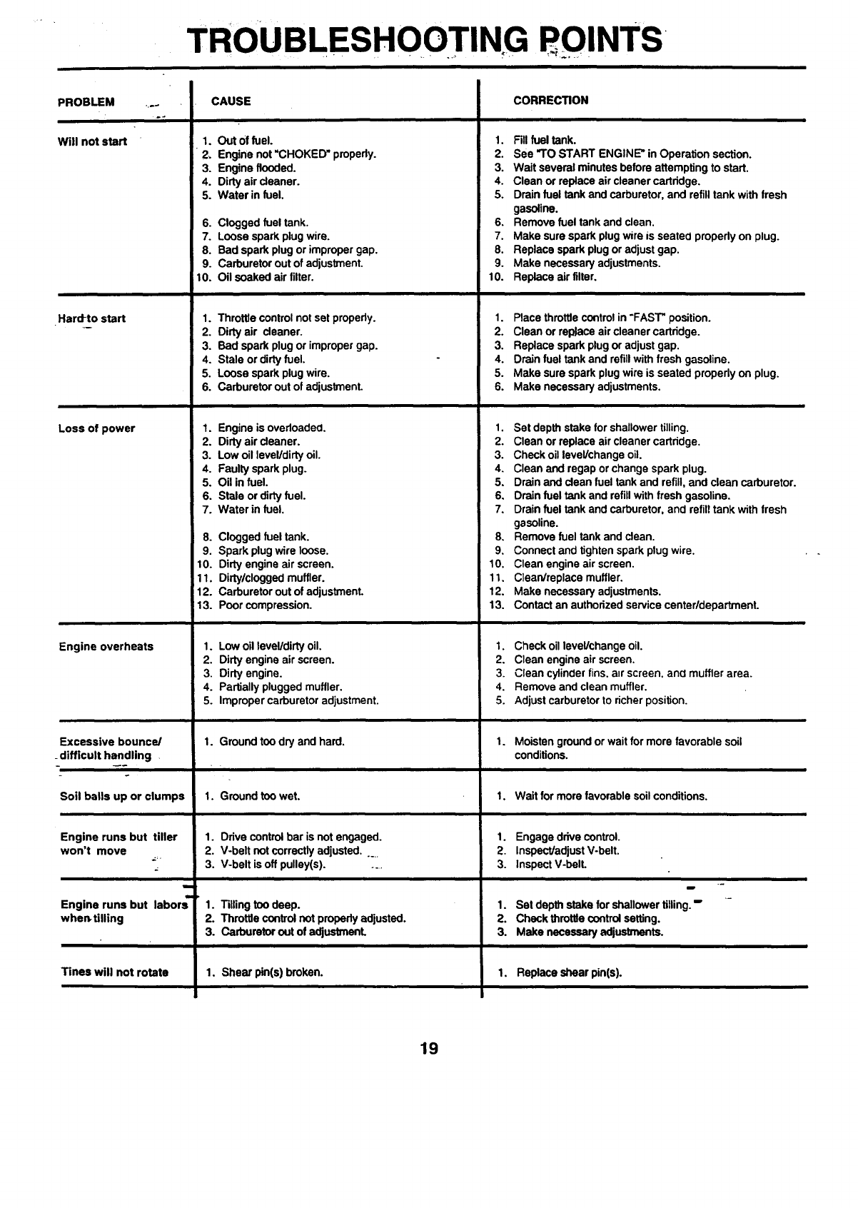
TROUBLESHOOTING DINTS
PROBLEM ....
Will not start
Hard-to start
Loss of power
Engine overheats
Excessive bounce/
_difflcult handling .
Soil balls up or clumps
Engine runs but tiller
won't move
m
Engine runs but labors"
when, tilling
Tines will not rotate
CAUSE
1. Out 0f fuel.
2. Engine not "CHOKED" pmpedy.
3. Engine flooded.
4. Dirty air cleaner.
5. Water in fuel.
6. Clogged fuel tank.
7. Loose spark plug wire.
8. Bad spark plug or improper gap.
9. Carburetor out of adjustment.
10. Oil soaked air filter.
1. Throttle control not set properly.
2. Dirty air cleaner.
3. Bad spark plug or improper gap.
4. Stale or dirty fuel.
5. Loose spark plug wire.
6. Carburetor out of adjustment.
1. Engine is ovedoadeO.
2. Dirty air cleaner.
3. Low oil level/dirty oil.
4. Faulty spark plug.
5. Oil in fuel.
6. Stale or dirty fuel.
7. Water in fuel.
CORREC_ON
1. Fillfuel tank.
2. See "TO START ENGINE" in Operation section.
3. Wait several minutes before attempting to start.
4. Clean or replace air cleaner cartridge.
5. Drain fuel tank and carburetor, and refill tank with fresh
gasoline.
6. Remove fuel tank and clean,
7. Make sure spark plug wire is seateO propedy on plug.
8. Replace spark plug or adjust gap.
9. Make necessary adjustments.
10. Replace airfilter,
8. Clogged fuel tank.
9. Spark plug wire loose.
10. Dirty engine air screen.
11. Dirtylclogged muffler.
12. Carburetor out of adjustment.
13. Poor compression.
1. Low oil level/dirty oil.
2. Dirty engine air screen.
3. Dirty engine.
4. Partially plugged muffler.
5. Improper carburetor adjustment.
1. Placethrottlecontrolin-FAST"position.
2. Cleanorreplaceaircleanercartridge.
3. Replacesparkplugoradjustgap.
4. Drainfueltankandrefillwithfreshgasoline.
5. Makesure sparkplugwireis seatedproperlyon plug.
6. Makenecessaryadjustments.
1. Set depth stake for shallower tilling.
2. Clean or replace air cleaner cartridge.
3. Check oil level/change oil.
4. Clean and regap or change spark plug.
5, Drain and clean fuel tank and refill, and clean carburetor.
6. Drain fuel tank and refill with fresh gasoline.
7. Drain fuel tank and carburetor, and refill tank with fresh
gasoline.
8, Remove fuel tank and clean.
9, Connect and tighten spark plug wire.
1. Ground too dry and hard.
1. Ground too wet.
1. Drive control bar is not engaged.
2. V-belt not correctly adjusted.....
3, V-belt is off pulley(s) .....
1. Tilling too deep.
2. Throttle control not properly adjusted.
3. Carburetor out of adjustmonL
1. Shear pin(s) broken.
10, Cleanengineairscreen.
11, Clean/replacemuffler.
12. Makenecessaryadjustments.
13. Contactanauthorizedservicecenterldepartment.
1. Check oil level/change oil.
2. Clean engine air screen.
3. Clean cylinOer fins. a_rscreen, ana muffler area.
4. Remove and clean muffler.
5. Adjust carburetor to richer position.
1. Moisten ground or wait for more favorable soil
conditions.
1. Wait for more favorable soil conditions.
1. Engage drive control.
2. Inspect/adjust V-belt.
3. Inspect V-belt.
!
1. Set depth stake for shallower tilling. "
2. Check throttle control setting.
3. Make necessary adjustments.
1. Replaceshearpin(s).
19
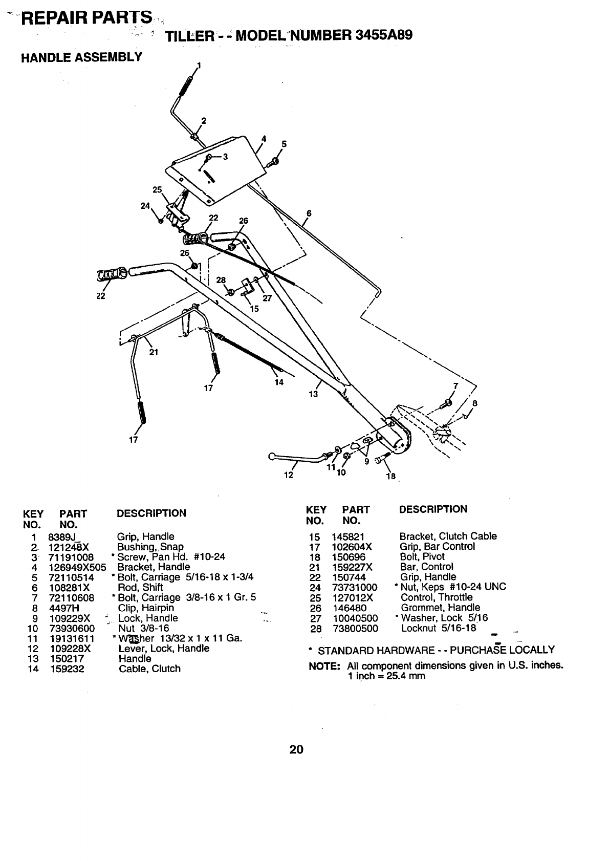
.....REPAIR PARTS,
_" '" TILLER- -_MODELNUMBER 3455A89
HANDLE ASSEMBLY ........
2
5
24
25
26
22 26 6
\
Z2
21
17
15
14
\
13 8
17
12 1110 18
KEY
NO.
1
2-
3
4
5
6
7
8
9
10
11
12
13
14
PART DESCRIPTION
NO.
8389J_ Grip, Handle
121248X Bushing,.Snap
71191008 * Screw, Pan Hd. #10-24
126949X505 Bracket, Handle
72110514 *Bolt, Carriage 5/16-18 x 1-3/4
108281X Rod, Shift
72110608 * Bolt, Carriage 3/8-16 x I Gr. 5
4497H Clip, Hairpin
109229X _ Lock, Handle
73930600 Nut 3/8-16
19131611 * Wi_her 13132 x 1 x 11 Ga.
109228X Lever, Lock, Handle
150217 Handle
159232 Cable, Clutch
KEY PART DESCRIPTION
NO. NO.
15 145821 Bracket, Clutch Cable
17 102604X Grip, Bar Control
18 150696 Bolt, Pivot
21 159227X Bar, Control
22 150744 Grip, Handle
24 73731000 *Nut, Keps #10-24 UNC
25 127012X Control, Throttle
26 146480 Grommet, Handle
27 10040500 "Washer, Lock 51.16
28 73800500 Locknut 5116-18
* STANDARD HARDWARE -- PURCHAKE LOCALLY
NOTE: All component dimensions given in U.S. inches.
1 inch = 25.4 mm
2O
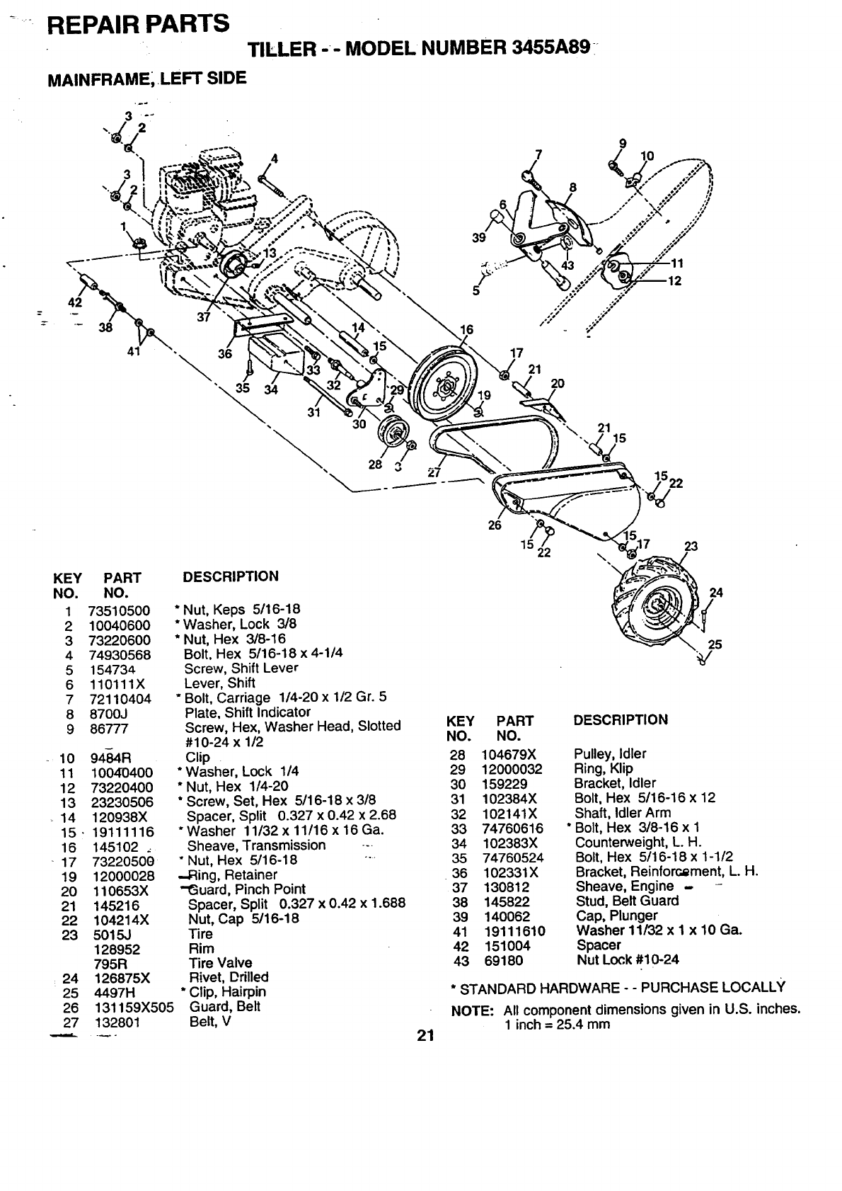
REPAIR PARTS
TILLER -- MODEL NUMBER 3455A89
MAINFRAME; LEFT SIDE
•37
\36
3O
28
:t
\
17
21 20
2115
3 27
KEY
NO.
1
2
3
4
5
6
7
8
9
10
11
12
13
_14
15.
16
17
19
20
21
22
23
24
25
26
27
PART
NO.
73510500
10040600
73220600
74930568
154734
110111X
72110404
8700J
86777
94-84R
10040400
73220400
23230506
120938X
19111116
145102 .
73220500
12000028
110653X
145216
104214X
5015J
128952
795R
126875X
4497H
131159X505
132801
DESCRIPTION
* Nut, Keps 5/16-18
*Washer, Lock 3/8
* Nut, Hex 3/8-16
Bolt, Hex 5/16-18 x 4-1/4
Screw, Shift Lever
Lever, Shift
"Bolt, Carriage 1/4-20 x 1/2 Gr. 5
Plate, Shift Indicator
Screw, Hex, Washer Head, Slotted
#10-24 x 1/2
Clip
* Washer, Lock 1/4
*Nut, Hex 1/4-20
*Screw, Set, Hex 5/16-18 x 3/8
Spacer, Split 0.327 x 0.42 x 2.68
*Washer 11/32x 11/16x 16Ga.
Sheave, Transmission --
" Nut, Hex 5/16-18 -
.-Ring, Retainer
-ISuard, Pinch Point
Spacer, Split 0.327 x 0.42 x 1.688
Nut, Cap 5/16-18
Tire
Rim
Tire Valve
Rivet, Drilled
* Clip, Hairpin
Guard, Belt
Belt, V 21
23
24
25
KEY PART DESCRIPTION
NO. NO.
28 104679X Pulley, Idler
29 12000032 Ring, Klip
30 159229 Bracket, Idler
31 102384X Bolt, Hex 5/16-16 x 12
32 102141X Shaft, Idler Arm
33 74760616 * Bolt, Hex 3/8-16 x 1
34 102383X Counterweight, L. H.
35 74760524 Bolt, Hex 5/16-18 x 1-112
.36 102331X Bracket, Reinforcement, L. H.
37 130812 Sheave, Engine - -
38 145822 Stud, Belt Guard
39 140062 Cap, Plunger
41 19111610 Washer 11/32 x I x 10 Ga.
42 151004 Spacer
43 69180 Nut Lock #10-24
* STANDARD HARDWARE --PURCHASE LOCALLY
NOTE: All component dimensions given in U.S. inches.
1 inch = 25.4 mm
REPAIR PARTS
TILLER'- 'MODEIL' NUMBER 3455A89
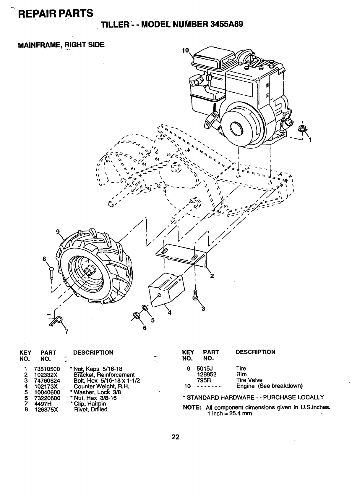
MAINFRAME,.RIGHT SIDE
10\
7 6
KEY
NO.
1
2
3
4
5
6
7
8
PART DESCRIPTION KEY PART DESCRIPTION
NO. "" ;T. NO. NO.
73510500
102332X
74760524
102173X
10040600
73220600
4497H
126875X
*N_, Keps 5/16-18
Br'Ecket,Reinforcement
Bolt, Hex 5/16-18 x 1-1/2
Counter Weight, R.H.
*Washer, Lock 3/8
*Nut, Hex 3/8-16
*Clip, Hairpin
Rivet, Drilled
10
5015J Tire
128952 Rim
795R Tire Valve
....... Engine (See breakdown)
"STANDARD HARDWARE --PURCHASE LOCALLY
NOTE: All component dimensions given in U.S.inches.
1 inch = 25.4 mm
22
REPAIR PARTS
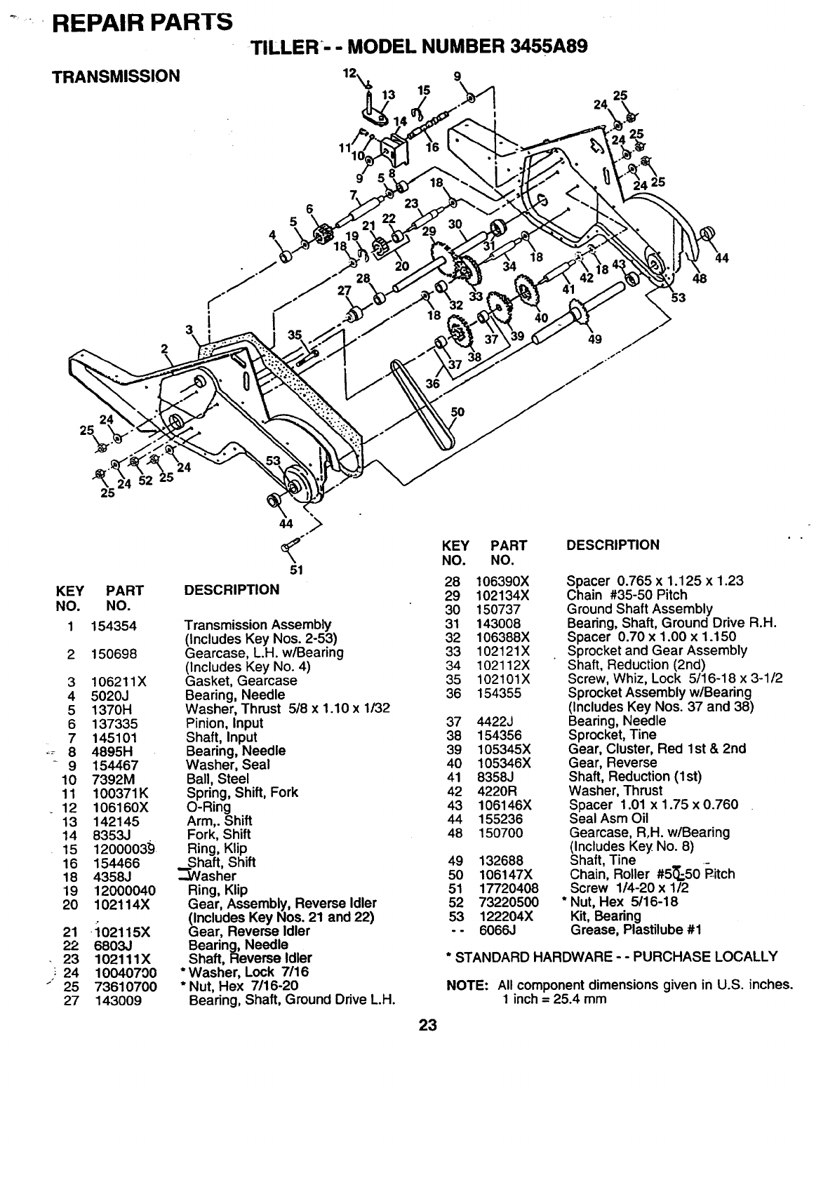
TRANSMISSION
TILLER'- - MODEL NUMBER 3455A89
12_ 9
315 \
I
25
56
25
24
2
i18
5O
53
44
48
25
KEY PART
NO. NO.
1154354
2150698
3 106211X
4 5020J
5 1370H
6 137335
7 145101
8 4895H
9 154467
10 7392M
11 100371K
12 106160X
13 142145
14 8353J
15 1200003_
16 154466
18 4358J
19 12000040
20 102114X
21 -102115X
22 6803J
23 102111X
24 10040700
25 73610700
27 143009
DESCRIPTION
Transmission Assembly
(Includes Key Nos. 2-53)
Gearcase, L.H. w/Bearing
(Includes Key No. 4)
Gasket, Gearcase
Bearing, Needle
Washer, Thrust 5/8 x 1.10 x 1/32
Pinion, Input
Shaft, Input
Bearing, Needle
Washer, Seal
Ball, Steel
Spring, Shift, Fork
O-Ring
Arm,. Shift
Fork, Shift
Ring, Klip
._Svhaft,Shift
asher
Ring, Klip
Gear, Assembly, Reverse Idler
(Includes Key Nos. 21 and 22)
Gear, Reverse Idler
Bearing, Needle
Shaft, Reverse Idler
*Washer, Lock 7/16
*Nut, Hex 7/16-20
Bearing, Shaft, Ground Drive L.H.
23
KEY PART
NO. NO.
28 106390X
29 102134X
30 150737
31 143O08
32 106388X
33 102121X
34 102112X
35 102101X
36 154355
37 4422J
38 154356
39 105345X
40 105346X
41 8358J
42 4220R
43 106146X
44 155236
48 150700
49 132688
50 106147X
51 17720408
52 73220500
53 122204X
-- 6066J
DESCRIPTION
Spacer 0.765 x 1.125 x1.23
Chain #35-50 Pitch
Ground Shaft Assembly
Bearing, Shaft, Ground Drive R.H.
Spacer 0.70 x 1.00 x 1.150
Sprocket and Gear Assembly
Shaft, Reduction (2nd)
Screw, Whiz, Lock 5/16-18 x 3-1/2
Sprocket Assembly w/Bearing
(Includes Key Nos. 37 and 38)
Bearing, Needle
Sprocket, Tine
Gear, Cluster, Red 1st & 2rid
Gear, Reverse
Shaft, Reduction (1st)
Washer, Thrust
Spacer 1.01 x 1.75 x 0.760
Seal Asm Oil
Gearcase, Roll. w/Bearing
(Includes Key No. 8)
Shaft, Tine
Chain, Roller #5_-50 _itch
Screw 1/4-20 x 1/2
* Nut, Hex 5/16-18
Kit, Bearing
Grease, Plastilube #1
* STANDARD HARDWARE - - PURCHASE LOCALLY
NOTE: All component dimensions given in U.S. inches.
1inch= 25.4 mm
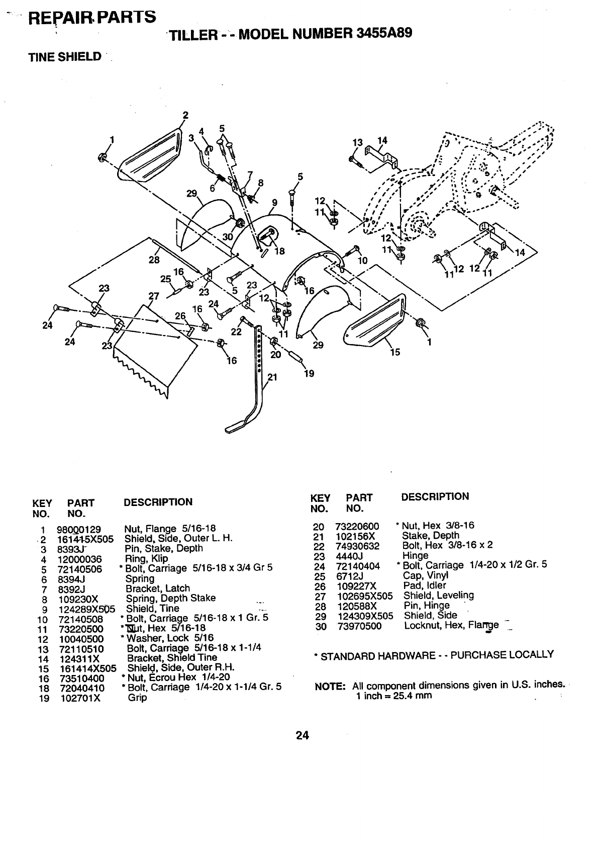
"REPAIR, PARTS
TINE SHIELD "
'TILLER"--MODEL NUMBER 3455A89
2
i_ 4 5 .-'::•
--'+"X ": - " '- " ""
KEY PART DESCRIPTION KEY PART DESCRIPTION
NO. NO. NO. NO.
198000129 Nut, Flange 5/16-18
•21614-1-5X505 Shield, Side, Outer L. H.
3 8393J- Pin, Stake, Depth
4 12000036 Ring, Klip
5 72140506 * Bolt, Carriage 5/16-18 x 3/4 Gr 5
6 8394J Spring
7 8392J Bracket, Latch
8 109230X Spring, Depth Stake
9 124289X5_5 Shield, Tine '
10 72140508 *Bolt, Carriage 5/16-18 x I Gr. 5
11 73220500 *'_JJt, Hex 5/16-18
12 10040500 * Washer, Lock 5116
13 72110510 Bolt, Carriage 5/16-18x 1-1/4
14 124311X Bracket, ShieldTine
15 161414X505 Shield, Side, Outer R.H.
16 73510400 * Nut, _crou Hex 1/4-20
18 72040410 * Bolt, Carriage 1/4-20 x 1-1/4 Gr. 5
19 102701X Grip
20 73220600 "Nut, Hex 3/8-16
21 102156X Stake, Depth
22 74930632 Bolt, Hex 3/8-16 x 2
23 4440J Hinge
24 72140404 * Bolt, Carriage 1/4-20 x 1/2 Gr. 5
25 6712J Cap, Vinyl
26 109227X Pad, Idler
27 102695X505 Shield, Leveling
28 120588X Pin, Hinge
29 124309X505 Shield, Side
30 73970500 Locknut, Hex, Flamj_e -
* STANDARD HARDWARE - - PURCHASE LOCALLY
NOTE: All component dimensions given in U.S. inches.
1 inch = 25.4 mm
24

RFPAIH PAH I :5
TINE ASSEMBLY
TILL'ER- -MODEL NUMBER 3455A89
5
\
11 9
9
KEY
NO.
1
2
3
4
5
6
7
PART
NO.
4459J
132673
6554J
3146R
132727 -'
7361060(7'
10040600
DESCRIPTION
Tine, Outer, L.H.
Clevis Pin
Tine, Inner, L.H.
* Clip, Hairpin
Assembly, Hub and Plate, L.H:_
Nut, Hex 3/8-24
"-Washer, Lock 3/8
_==0=
KEY PART
NO. NO.
874610616
94460J
10 132728
11 6555J
DESCRIPTION
Bolt, Hex 3/8-24 x 1
Tine, Outer, R.H.
Assembly, Hub and Plate, R.H.
Tine, Inner, R.H.
* STANDARD HARDWARE--PURCHASE LOCALLY
NOTE: All component dimensions given in_U.S, inches.
1 inch = 25.4 mm
25

_FII_PAIH I_AH I
DECALS
TILLER, MODEL NUMBER:3455A89
3
4
11
6
5
7
9\
KEY PART
NO. NO.
1 162998
2 127521
3146353
4110655X
5 120431X
6 102180X
7 162215
9 120075X
11 156199
- - 163002
DESCRIPTION
Decal, Logo
Decal, USA BIk
Decal, Logo
Decal, Instruction, Tilling
Decal, Hand Placement
Decal, Shift Indicator
Decal, Warning
Decal, Waming, Rotaung Tines
Decal, Control Pnl. Rev.
Manual, Owner's
26
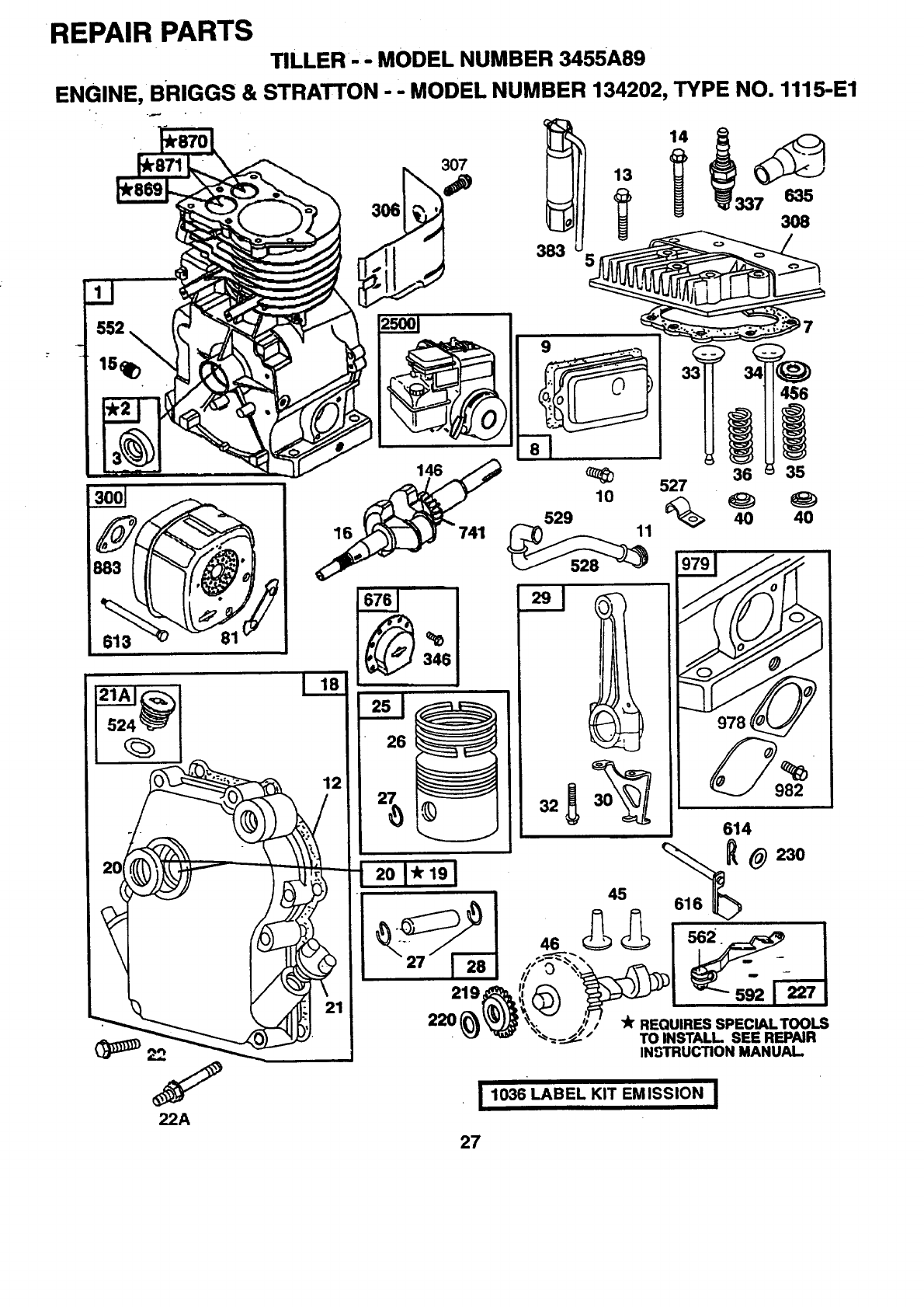
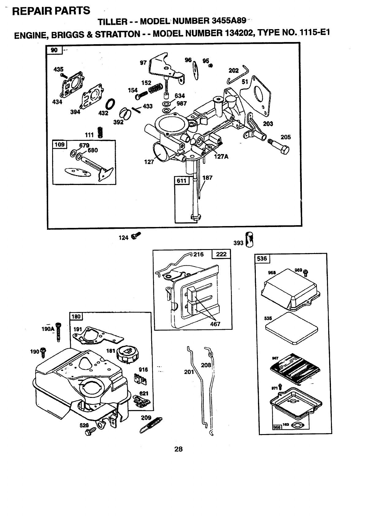
REPAIR PARTS
TILLER-- MODEL NUMBER 3455A89
ENGINE, BRIGGS & STRATTON - - MODEL NUMBER 134202, TYPE NO. 1115-E1
306
307
383
552 25001
Y
22A
16
12
741
I
26_
9
_6
527 36 35
45
219,
22O -Jr REQUIRESSPECIALTOOLS
TO INSTALL. SEE REPAIR
IN_rRUCTION MANUAL
1036 LABEL KIT EMISSION I
27
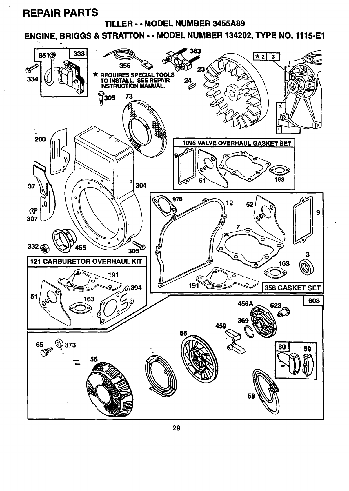
REPAIR PARTS
TILLER - - MODEL NUMBER 3455A89 .....
ENGINE, BRIGGS & STRATTON - - MODEL NUMBER 134202, TYPE NO. 1115-E1
435
434
127
187
679
i
127A
205
%
190t
124 393 _
216 1222
28
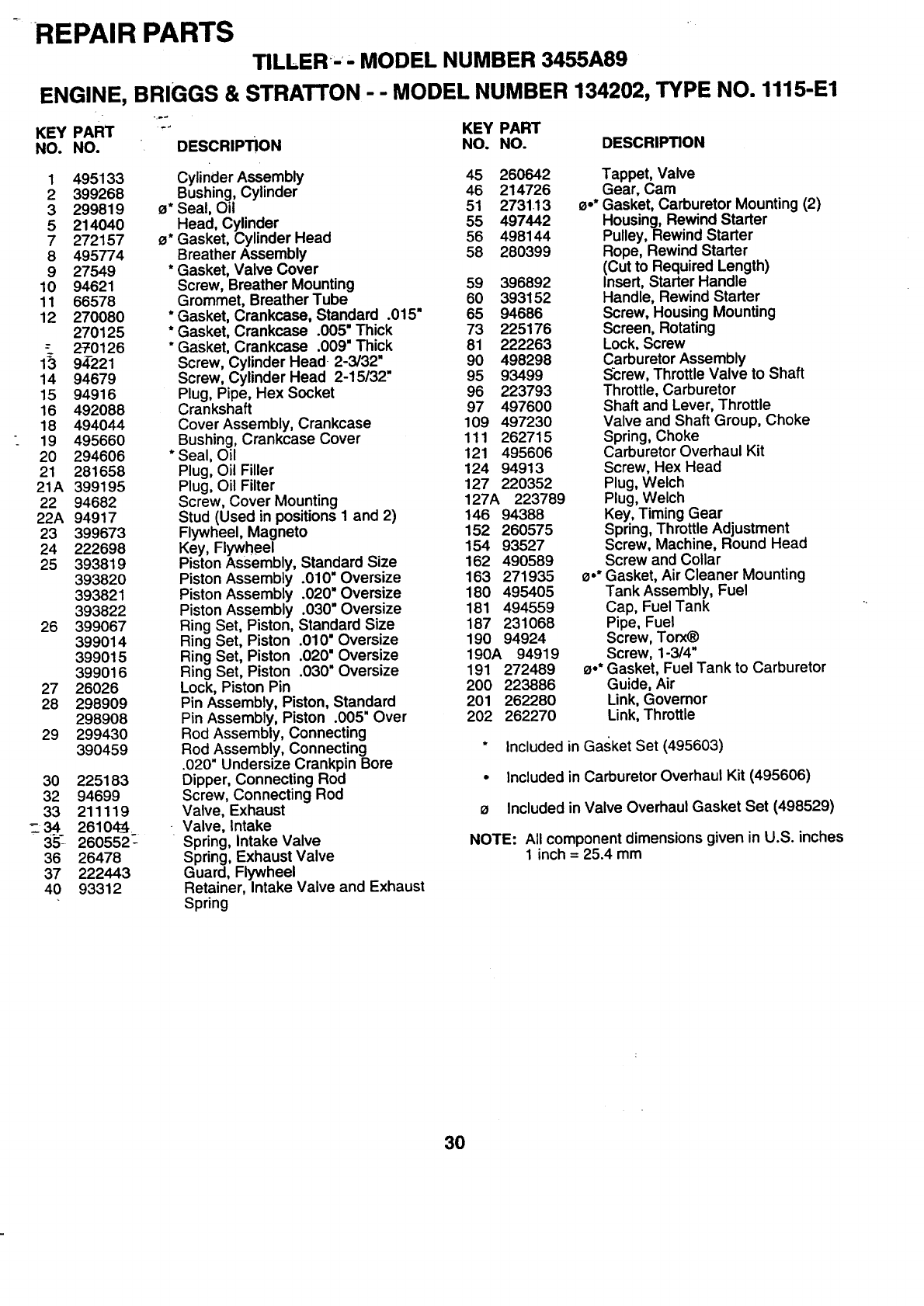
REPAIR PARTS
TILLER - - MODEL NUMBER 3455A89
ENGINE, BRIGGS & STRATTON -- MODEL NUMBER 134202, TYPE NO. 1115-E1
l,
37
200
REQUIRES SPECIAL TOOLS
TO INSTALL SEE REPAIR 24_
INSTRUCTION MANUAL
305 73
3O4
1095 VALVE OVERHAUL GASKET SET
307
332 (_
121 CARBURETOR OVERHAUL KIT
/__394
51/__YI 163 _u_._,
65 373
t
imp
58
29
REPAIR PARTS
TILLER MODEL NUMBER 3455A89
ENGINE, BRIGGS & STRA'rFON
KEY PART ""
NO. NO. DESCRIPTION
--MODEL NUMBER 134202, TYPE NO. 1115-E1
KEY PART
NO. NO. DESCRIPTION
1495133
2399268
3 299819
5 214040
7272157
8495774
9 27549
10 94621
11 66578
12 270080
270125
270126
13 94-221
14 94679
15 94916
16 492088
18 494044
19 495660
20 294606
21 281658
21A 399195
22 94682
22A 94917
23 399673
24 222698
25 393819
393820
393821
393822
26 399067
399014
399015
399016
27 26026
28 298909
298908
29 299430
390459
30 225183
32 94699
33 211119
_34 26104_
35_260552 _
36 26478
37 222443
40 93312
Cylinder Assembly
Bushing, Cylinder
0* Seal, Oil
Head, Cylinder
0* Gasket, Cylinder Head
Breather Assembly
*Gasket, Valve Cover
Screw, Breather Mounting
Grommet, Breather Tube
* Gasket, Crankcase, Standard .015"
* Gasket, Crankcase .005" Thick
* Gasket, Crankcase .009" Thick
Screw, Cylinder Head• 2-3/32"
Screw, Cylinder Head 2-15/32"
Plug, Pipe, Hex Socket
Crankshaft
Cover Assembly, Crankcase
Bushing, Crankcase Cover
* Seal, Oil
Plug, Oil Filler
Plug, Oil Filter
Screw, Cover Mounting
Stud (Used in positions I and 2)
Flywheel, Magneto
Key, Flywheel
Piston Assembly, Standard Size
Piston Assembly .010" Oversize
Piston Assembly .020" Oversize
Piston Assembly .030" Oversize
Ring Set, Piston, Standard Size
Ring Set, Piston .010" Oversize
Ring Set, Piston .020" Oversize
Ring Set, Piston .030" Oversize
Lock, Piston Pin
Pin Assembly, Piston, Standard
Pin Assembly, Piston .005" Over
Rod Assembly, Connecting
Rod Assembly, Connecting
.020" Undersize Crankpin Bore
Dipper, Connecting Rod
Screw, Connecting Rod
Valve, Exhaust
•Valve, Intake
Spring, intake Valve
Spring, Exhaust Valve
Guard, Flywheel
Retainer, Intake Valve and Exhaust
Spring
45 280642 Tappet, Valve
46 214726 Gear, Cam
51 2731.13 o.* Gasket, Carburetor Mounting (2)
55 497442 Housing, Rewind Starter
56 498144 Pulley, Rewind Starter
58 280399 Rope, Rewind Starter
(Cut to Required Length)
59 396892 Insert, Starter Handle
60 393152 Handle, Rewind Starter
65 94686 Screw, Housing Mounting
73 225176 Screen, Rotating
81 222263 Lock, Screw
90 498298 Carburetor Assembly
95 93499 Sc:rew, Throttle Valve to Shaft
96 223793 Throttle, Carburetor
97 497600 Shaft and Lever, Throttle
109 497230 Valve and Shaft Group, Choke
111 262715 Spring, Choke
121 495606 Carburetor Overhaul Kit
124 94913 Screw, Hex Head
127 220352 Plug, Welch
127A 223789 Plug, Welch
146 94388 Key, Timing Gear
152 260575 Spring, Throttle Adjustment
154 93527 Screw, Machine, Round Head
162 490589 Screw and Collar
163 271935 o,* Gasket, Air Cleaner Mounting
180 495405 Tank Assembly, Fuel
181 494559 Cap, Fuel Tank
187 231068 Pipe, Fuel
190 94924 Screw, Torx_
190A 94919 Screw, 1-3/4"
191 272489 0°* Gasket, Fuel Tank to Carburetor
200 223886 Guide, Air
201 262280 Link, Governor
202 262270 Link, Throttle
Included in Gasket Set (495603)
• Included in Carburetor Overhaul Kit (495606)
oIncluded in Valve Overhaul Gasket Set (498529)
NOTE: All component dimensions given in U.S. inches
1 inch = 25.4 mm
3O
REPAIR PARTS
....TILLER - - MODEL NUMBER 3455A89
ENGINE, BRIGGS & STRATTON --MODEL NUMBER 134202, TYPE NO. 1115-E1
KEY PART. "" KEY PART
NO. NO. DESCRIPTION NO. NO. DESCRIPTION
203 280720 Bell Crank 542 94897
205 231520 Screw, Shoulder 552 231079
208 262279 Rod, Speed Control 562 94907
209 262248 Spring, Governor 592 231978
216 262359 Link, Choke 608 497830
219 494845 Gear, Governor 611 391813
220 221551 Washer, Thrust 613 93935
222 490649 Panel, Control 614 93306
227 490374 Lever Assembly, Governor 616 495243
230 94927 Washer, Governor Lever 621 396847
256 223813 Crank, Bell 623 94943
300"__494585 Muffler, Exhaust 634 271853
304 495759 Housing, Blower 635 66538
"305 94786 Screw, Blower Housing Mounting 676 393757
306 224820 Shield, Cylinder 679 270382
307 94680 Screw, Cylinder Shield 680 221839
308 224738 Cover, Cylinder Head 741 262992
332 94877 Nut, Flywheel 779 262570
333 397358 Armature Group 851 493880
334 93414 Screw, Armature Mounting 869 211787
337 802592 Plug, Spark 870 263094
346 94896 Screw, Seres 871 262001
356 497833 Wire, Ground 63709
358 495603 Gasket Set 883 272228
363 19069 Flywheel Puller 916 280321
369 263073 Spring 966 492797
373 94908 Nut, Hex 967 491588
383 89838 Wrench, Spark Plug 968 495872
392 262328 Spdng, Fuel Pump Diaphragm 969 490073
393 225058 Screen 971 94902
394 272538 •Diaphragm 978 273326
414 220982 Washer 979 494807
432 221377 Cap, Spring 982 94658
433 93265 Pin, Diaphragm Cover 987 398970
434 213963 Cover, Diaphragm 995 225057
435 93141 Screw, Diaphragm Cover 1012 490507
455 225121 Cup, Starter 1036 499345
456 225257 Retainer Spring 1095 498529
456A 281503 Retainer 2500 134202-0114
459 281505 Pawl, Starter 495952
467 280715 Knob, Control
524 271485 * Seal, O-Ring
--526 94914 Screw, Sems, Tank Bracket Mount.
527 223786 Clamp, Breather Tube
528 231550 Tube, Breather
529 67838 Grommet, Breather Tube
535 491435 Filter, Air
536 494279 Cleaner, Air
Screw
Bushing, Governor Crank
Bolt, Governor Lever
Nut, Hex
Starter Assembly, Rewind
Fuel Pipe and Clip Assembly
Screw, Hex Head, Shoulder
Pin, Cotter
Crank, Governor
Switch, Stop
Screw, Shoulder
Washer, Throttle Shaft, Foam
. Elbow, Spark Plug
Deflector, Exhaust. Side Outlet
Washer, Foam
Washer, Brass
Gear, Timing
Link
Cable Terminal, Ignition
Seat, Intake Valve, Standard
Seat, Exhaust Valve, Standard
Guide, Exhaust Valve
Guide, Intake Valve
Gasket, Exhaust
Rack, Gear Control
Base, Air Cleaner
Filter, Air Cleaner
Cover, Air Cleaner
Screw, Air Cleaner
Screw, Hex Head
Gasket, Cover
Cover, Oil Guarde)
Screw, Hex Head
Seal, Throttle Shaft
Lever, Bracket Assembly
Retainer, Link
Label Kit, Emission
Gasket Set, Valve Overhaul
Replacement Engine
Replacement Shortblock
RPM Settings: Low: 1200-1600, High: 3500-3700
" Included in Gasket Set (495603)
•Included in Carburetor Overhaul Kit (495606)
oIncluded in Valve Overhaul Gasket Set (498529)
NOTE: All component dimensions, given in U.S. inches
1 inch = 25.4 mm
31
HOW AND WHERE TO ORDER PARTS
You can identify your product correctly by looking at its model number label which is located on top of the
transmission.
1. A. Name the product that needs a part, for example: tiller.
B. State the product's model number and factory number. These numbers appear on a label on the product.
2. Listthe description and partnumberof the partyou want. This manual showsdrawings, descriptions, and part
numbers.
3. You may order from a participatingWestern Auto store. If you cannot do thaL please order direct from:
Telephone: 1-800-633-8434
Western Auto National Parts Center
2107 Grand Avenue
Kansas City, MO 64108
163002 10.29.97 TR
PI_E_ U.S.A.
