Westhold TXDP-01 Race Car Transmitter User Manual Westhold Corporation
Westhold Corporation Race Car Transmitter Westhold Corporation
UserManual.wiki
>
Westhold
>
TXDP-01 User Manual
>
Manual
Contents
1.
Instructions
2.
Manual
Manual
Navigation menu
Upload a User Manual
Namespaces
Wiki Guide
HTML
PDF
Info
Views
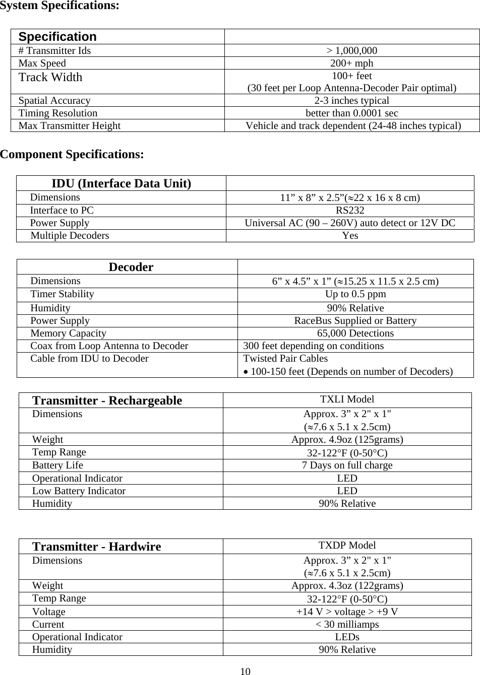
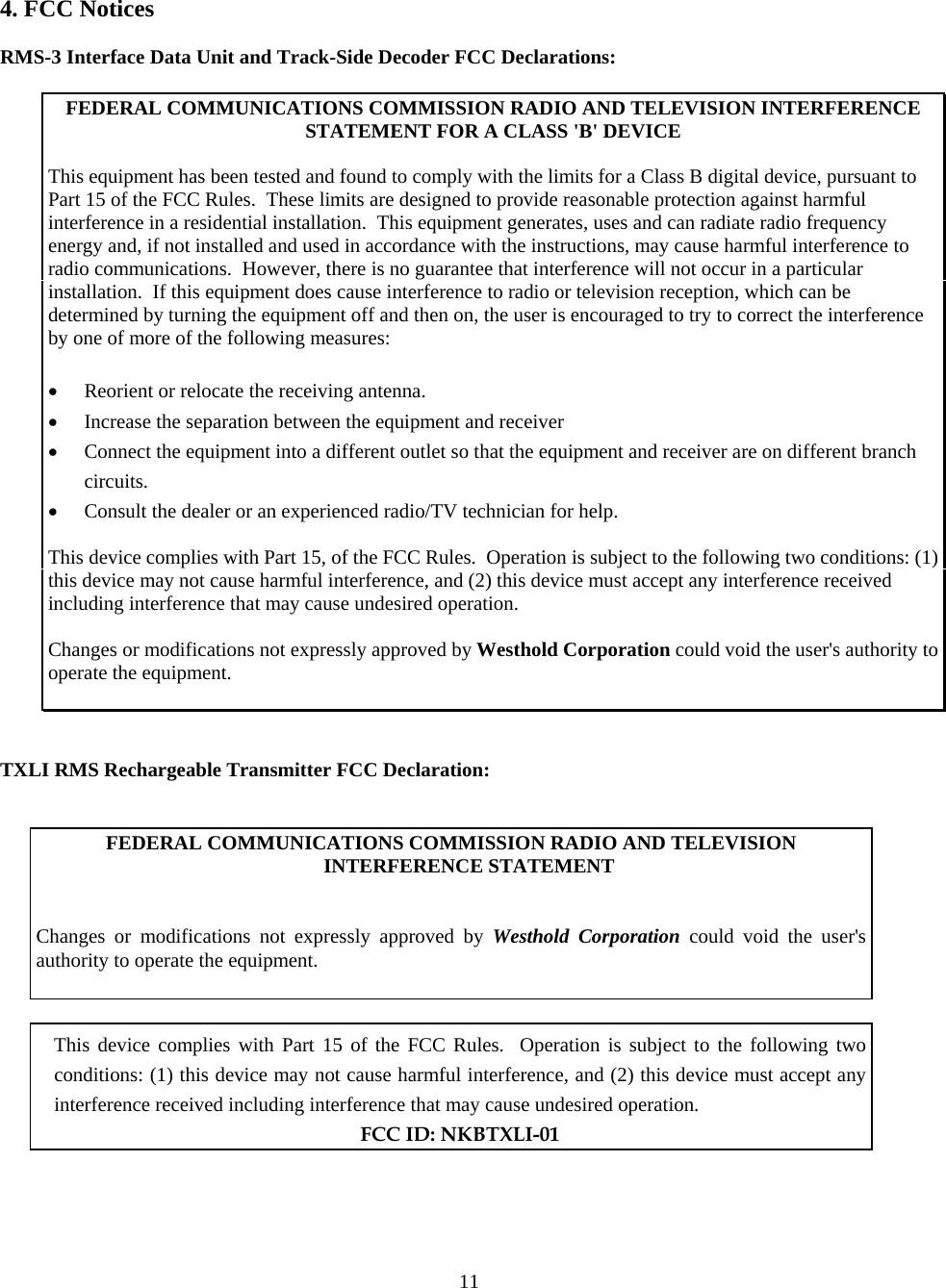
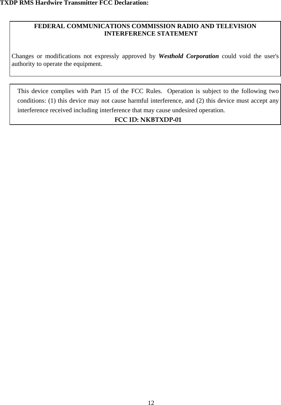
User Manual
Discussion / Help
Navigation