Westhold TXDP-01 Race Car Transmitter User Manual Westhold Corporation
Westhold Corporation Race Car Transmitter Westhold Corporation
Westhold >
Contents
- 1. Instructions
- 2. Manual
Manual

Race Management System
Instruction Manual
Westhold Corporation General Warranty
Modules and other equipment ("Goods") purchased from Westhold Corporation are warranted against defects in
materials and workmanship under normal use for a period of three years from the date of purchase. In the event of
product failure due to defects in materials or workmanship, the customer may return the defective product to
Westhold Corporation for repair or replacement. The customer is responsible for all shipping charges associated
with shipping the Goods back to Westhold Corporation. Westhold Corporation pays shipping charges associated
with the return of Goods back to the customer. As Westhold Corporation will not be responsible for damages
incurred during any incoming shipment, it is recommended that the customer insure their shipment through their
carrier.
Westhold Corporation shall, at its sole option, repair or replace the Goods. Repair or replacement of Goods is
Westhold Corporation's sole obligation and the customer's exclusive remedy for all claims of defects. If that remedy
is adjudicated insufficient, Westhold Corporation shall refund the customer's paid price for the Goods and have no
other liability to the customer.
Westhold Corporation's software, if included with Goods, is sold as is, and this warranty is inapplicable to such
software.
This warranty does not cover and Westhold Corporation will not be liable for, any damage or failure caused by
misuse, abuse, acts of God, accidents, electrical irregularity, or other causes beyond Westhold Corporation's control,
or claim by other than the original purchaser. This warranty is void if Westhold Corporation, in its sole discretion,
determines that there has been any:
1. Tampering, signs of tampering, alteration, modification, or other indications or abuse.
2. Application of power outside of the voltage level and polarity specified in the data sheet or user's manual.
3. Repair or attempt to repair by anyone other than a Westhold Corporation authorized technician.
This is our entire warranty and is given in lieu of all other possible warranties, either express or implied, including
warranties of merchantability and of fitness for a particular purpose. By accepting delivery of the Goods,
Purchaser/User waives all other possible warranties, except those specifically given.
IN NO EVENT SHALL WESTHOLD CORPORATION BE LIABLE FOR ANY CONSEQUENTIAL,
INCIDENTAL, INDIRECT, SPECIAL OR PUNITIVE DAMAGES ARISING OUT OF OR RELATING IN
ANY WAY TO ANY DEFECT IN OR FAILURE OF OR INABILITY TO USE THE GOODS, INCLUDING
BUT NOT LIMITED TO, CLAIMS BASED UPON LOSS OF USE, LOSS OF TIME, INCONVENIENCE,
COMMERCIAL LOSS, LOST PROFITS, REVENUE OR SAVINGS, LOST GOODWILL,
ENVIRONMENTAL DAMAGE, INCREASED EXPENSES OF OPERATION, COST OF REPLACEMENT
GOODS, OR CLAIMS OF THE CUSTOMER OR CUSTOMER'S CUSTOMERS, WHETHER OR NOT
BASED ON CONTRACT, TORT (INCLUDING NEGLIGENCE AND STRICT LIABILITY) OR
OTHERWISE. WESTHOLD CORPORATION’s MAXIMUM LIABILITY UNDER THIS WARRANTY
SHALL NOT EXCEED THE PAID PRICE FOR THE GOODS UPON WHICH SUCH LIABILITY IS
BASED AND ALL SUCH LIABILITY SHALL TERMINATE NO LATER THAN ONE YEAR FROM THE
DATE OF DELIVERY OF THE GOODS.
Note: Westhold Corporation’s Goods are sold for resale or for commercial purposes, and are thus not covered
under the Magnuson-Moss Warranty Act.
1. Introduction
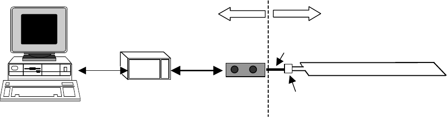
The Westhold RMS-3 is a sophisticated multi-component system used for the timing, scoring
and management of motor sports racing events. The RMS-3 consists of electronic hardware and
PC based MS-Windows® software. A basic hardware setup includes a computer, Interface Data
Unit (IDU), Decoder, Loop Antenna, and transmitters. See fig. 1.1
3
(fig 1.1 - Basic RMS Configuration)
RS-232
Decoder Loop Antenna
(
e.
g
. Located at Start/Finish
)
Coax
IDU
RaceBus
Link
Outside of scoring buildin
g
- Track-side
Inside scoring building
Balun
Computer
Each transmitter transmits a unique identification number. When a transmitter crosses a Loop
Antenna, a Decoder reads this number and determines the crossing time of the transmitter. The
Decoder sends this information to the IDU via the digital RaceBus network link. The IDU
compiles all of the information and sends it to the computer over a serial link for final analysis
and storage. Data can then be sent from the computer to other devices such as scoreboards,
driver results printers, hand-held controllers and third party devices.
The Interface Data Unit (IDU) acts as the central data management junction between the
computer, Decoder, and additional devices. It coordinates both incoming and outgoing signals to
and from the computer, synchronizing data for the entire system. The IDU intelligently
organizes and filters data for the PC. This frees the PC from handling all the overhead of
managing the RaceBus network and allows the overall system to maintain reliable real-time
operation. Only a single IDU is needed per system. Each IDU can handle dozens of Decoders.
The Decoder is a receiver system that processes the raw signals picked up by the Loop Antenna.
Its job is to convert the raw signals into digital information that can then be transmitted via the
RaceBus to the IDU. Multiple Decoders may be attached to the RaceBus to cover multiple
timing points for information such as split times (see fig. 1.2) or pit row activity. Decoders may
also be attached to each other in a daisy-chained configuration to cover wide tracks. See fig 1.3.
Each Decoder stores what are known as hit records. Hit records describe the crossing of
transmitters over the Loop Antennas. Each record consists of a transmitter identification
number, the crossing time as well as a few other pieces of information such as transmitter battery
status. The Decoder is capable of storing 65,000 hit records and capable of determining a
crossing time with spatial accuracy typically between 2-3 inches. Under normal operation, the
PC would upload this data and process it as the transmitters cross the Loop Antennas. However,
in the event of a computer failure for example, the Decoders would still contain the information
necessary to recreate a race.
b
alun Coax cable
Coax cable
Loop Antenna
(Timing point 1)
RaceBus
(Cat 5 type Cable)
Decoder Decoder
Loop Antenna
(Timing point 2)
b
alun
IDU
(fig 1.2 - Multiple Timing Point Configuration)
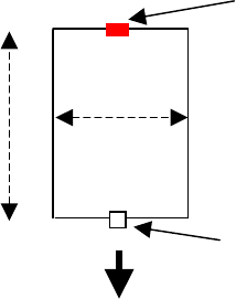
A Loop Antenna is simply insulated electrical wire with a terminating resistor on the side of the
loop furthest from the connection to the Decoder. They are buried beneath the surface of the
track and are 24 inches (approx. 60 cm) wide and can be of varying length to cover the width of
the track. See fig 1.4. The optimal length is approximately 30 feet. However, the length may be
longer with the tradeoff being detection height of the transmitters with respect to the antenna. In
other words, the longer the antenna, the less detection height achieved.
The ends of the Loop Antenna connect to what is called a balun. It is a device that connects the
Loop Antenna to a RG58 (50 ohm) coax cable. The balun device matches the impedance
between the Loop Antenna section and the coax. It is necessary to have a balun device for
optimal performance. Without it the impedance mismatches can result in reduced detection
height and possibly intermittent and unpredictable behavior.
Terminating Resistor
balun
24”
30 feet (optimal)
(fig. 1.4 - Loop Antenna Dimensions)
4
Physically, the RaceBus is standard 4 pair (8 wire) network (Category 5) cabling found at many
computer stores. The RaceBus network architecture allows multiple devices, called Appliances,
to be attached to the network. For instance, the IDU and Decoder are both RaceBus Appliances.
Scoreboards, results monitors, results printers and other third party Appliances may also be
attached to the RaceBus. However, it is NOT possible to hook computer network equipment to
the RaceBus. Doing so may result in damaged equipment.
WARNING: Do not hook computer network equipment to the RaceBus cabling! Doing so
may damage your equipment.
2. Installation and Usage
2.0 General Notes
The first step in an installation is to carefully plan where each piece of the system will reside.
The plan must take into account the limitations of the system. Some of these limitations are
fixed. Others are variable and dependent upon the track environment.
2.1 Antenna Installation
There are two methods for setting up the antenna; the single loop and multi-loop methods. See
the figures 2.1 and 2.2 below for the single and two loop setups. All loops should be about 24
inches wide with the resistor centered at the end of the loops. For multi-loop antennas each loop
should overlap the adjacent loop about 2-3 feet.
Terminating Resistor
24”
30 Feet (recommended)
Balun
Coax (To Decode
r
)
(fig 2.1.1 – Single loop)
5
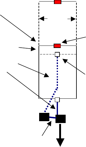
24 inches
Coax from
b
alun
Master
Decode
r
Slave Loop - Balun
Slightly
overlapped
antenna loops
Master Loop -
Terminatin
g
Resisto
r
Overlap of 2-3 feet
Diasy-chain
cable
6
RaceBus Data cable
(
Cat 5
)
to IDU
(fig 2.1.2 – Multi-loop)
Antenna loops are simply insulated copper electrical wire with a resistor soldered to the end of
the loop. If you prefer to make loops yourself or have a special need, the wire can be purchased
at most hardware stores while the resistor (450 ohm optimal) is available at many electronic
stores. The wire may be stranded or solid core. A typical gauge of wire used is AWG 20.
Smaller or larger gauges may be used. There are certain trade-offs to using smaller or larger
gauges. For example, a smaller gauge is generally less durable, but is often more flexible and
easier to manipulate.
Recommended:
Wire Type: Stranded core.
Resistor: Use approximately 450 ohms. Some deviation from this number is ok. Using a 400
ohm or 500 ohm resistor will not significantly affect the performance.
Heat shrink tubing: We suggest using heat shrink to encase the resistor and any exposed wire.
This will keep moisture from seeping into the wire and eating away the copper.
To install the antenna loop, cut a groove approximately ¼ inch (6-8 mm) wide and ½ inch (12-13
mm) deep in the track with the dimensions show below. See fig. 2.1.1. Depending on the wire
gauge the groove dimensions should be adjusted accordingly. For dirt tracks, place the antenna

loops in plastic PVC sprinkler pipes. Make sure the pipes are sealed such that water will not
enter the pipes.
There is no fixed depth to bury the antenna for dirt tracks. This is variable depending on the
track. Environmental factors such as metal content in the soil can reduce detection distance and
therefore the antenna cannot be buried as deeply as soil without metal content. The general rule
of thumb is to bury the antenna only as deep as necessary to keep the antenna from being
damaged, yet maintaining maximum detection distance between the antenna and the transmitter
on the vehicle. Generally keeping the antenna burial depth to less than 18 inches is
recommended. This typically is deep enough so cars and graders do not harm the antenna, but
still maintaining good detection distance.
Connect the ends of the Loop Antenna to the balun device. There are two screw terminals on the
device for the antenna wire. A BNC connector is on the opposite end of the balun. Connect the
coax cable to the BNC connector. The other end of the coax cable will then connect to the BNC
connector on the back of the Decoder.
2.2 Decoder
Decoders (Fig 2.2.1) may be connected to the system in two different manners—the standard
configuration and the daisy-chain configuration. In the standard configuration the Decoder
connects directly to the RaceBus. In the daisy-chain configuration one Decoder connects to the
tail end of another. The combined chain acts as a single Decoder. The daisy-chain configuration
is used when multiple loops are used to cover the width of a track.
DAIS
Y
COM
DET
COM
DET
Main
MAIN
Fig. 2.2.1 - Decoder
The Decoder has 5 LED indicators. When the Decoder is properly hooked up to the IDU and the
IDU is powered on, the power indicator LED (PWR) will turn on to indicate the unit is receiving
power from the IDU. The communication (COM) LED on the Main port will also turn on. If
there is a daisy-chain Decoder hooked to the unit the communication LED on the Daisy port will
also turn on. Each daisy-chain device will also have LEDs that indicate the same things as the
primary Decoder in the chain.
7
8
Note that when a transmitter is within detection distance of the antenna loop and Decoder, the
detection LED (DET) will turn on.
Each Decoder has two circular connectors. One end is labeled “Main” and the other is labeled
“Daisy.” Connect one end of the cat-5 cable with the circular connector to the Decoder. Connect
the RJ-45 end to one of the ports on the back of the IDU. If daisy-chained Decoders (multi-loop)
are required, connect the “Main” side of each subsequent Decoder in the chain to the “Daisy-
chain” end of the previous Decoder.
2.3 Interface Data Unit:
The IDU comes with a power cord and an RS-232 serial port connector. Plug the male side of
the RS-232 cord into the female connector on the IDU. Note that some older models have 2 RS-
232 ports. Take the other end of the RS-232 cord and plug that into the proper connector on the
computer that will run the system. Plug the power cord into the appropriate place on the IDU
and plug the other end into the appropriate wall outlet. Note that the IDU does not need a special
transformer to switch between 120V and 220V. The IDU has an intelligent auto-sensing power
supply.
The back of the IDU has 4 RJ-45 network connectors. This is used for the RaceBus connections.
All the RJ-45 ports are exactly the same. The multiple connectors are for user convenience.
Power to RaceBus appliances is supplied by the IDU. Note that there is a limit to the number of
appliances each IDU port may support power-wise. For example, each IDU port can currently
power 2 Decoders. However if the appliances have their own power supply, the RaceBus system
may support up to 32 devices total.
2.4 Transmitters
The transmitter is easy to install, operate and maintain. The lightweight and compact transmitter
operates using an internal non-removable battery. Each transmitter has a unique identification
code that is printed on the outside of the transmitter case. There are two LEDs, one green and
one red on the transmitters. When the transmitters are fully charged and operational they will
operate for 7 days. The green LED will blink rapidly every 3 seconds. The number of rapid
blinks indicates the number of days of charge left before the transmitter will shut off. When the
transmitter is on the last day, it will begin to blink the red LED once ever 3 seconds.
Transmitters are mounted on vehicles using one of two types of holders. One type of holder is a
plastic holder with two wings for bolting to a vehicle. The other type is a nylon fabric pouch
variety with wings for bolting to a vehicle. 9 volt transmitters do not need holders and can be
mounted directly to vehicles via their mounting ears. Be sure to securely fasten the transmitter to
the vehicle before use. Unsecured transmitters can be hazardous if they fall on the track.
The best possible orientation of the transmitter is shown below with the label side of the
transmitter facing the ground Fig 2.4.3. It is important that the transmitter has no metal or
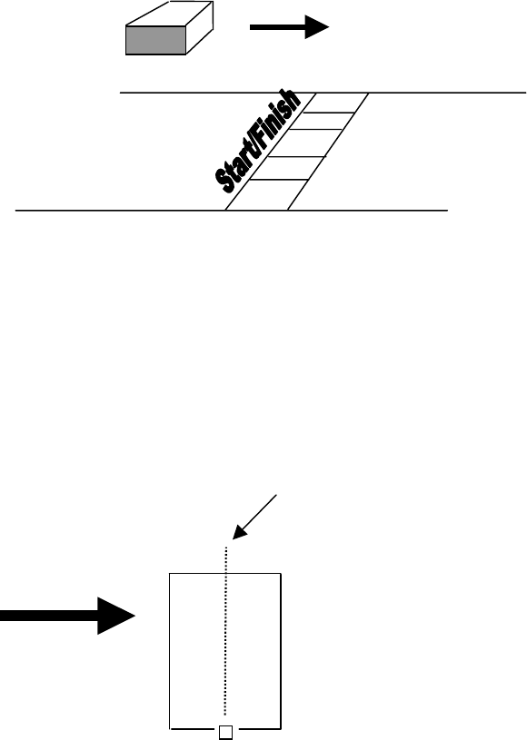
carbon fiber between it and the track surface. Metal and carbon fiber will block the signal
emanating from the transmitter and the Decoder will not be able to pick up crossing transmitters.
Direction of Travel
Fig 2.4.3
3. Specifications
The RMS is capable of detecting transmitter crossings over the middle of a Loop Antenna with a
spatial accuracy of typically 2-3 inches and a resolution of better than one ten-thousandths of a
second. For a transmitter traveling at 200 miles per hour, that translates into sub-millisecond
accuracy.
Midline of loop
Direction of
travel
(fig. 3.1 – Direction of travel)
9

10
System Specifications:
Specification
# Transmitter Ids > 1,000,000
Max Speed 200+ mph
Track Width 100+ feet
(30 feet per Loop Antenna-Decoder Pair optimal)
Spatial Accuracy 2-3 inches typical
Timing Resolution better than 0.0001 sec
Max Transmitter Height Vehicle and track dependent (24-48 inches typical)
Component Specifications:
IDU (Interface Data Unit)
Dimensions 11” x 8” x 2.5”(≈22 x 16 x 8 cm)
Interface to PC RS232
Power Supply Universal AC (90 – 260V) auto detect or 12V DC
Multiple Decoders Yes
Decoder
Dimensions 6” x 4.5” x 1” (≈15.25 x 11.5 x 2.5 cm)
Timer Stability Up to 0.5 ppm
Humidity 90% Relative
Power Supply RaceBus Supplied or Battery
Memory Capacity 65,000 Detections
Coax from Loop Antenna to Decoder 300 feet depending on conditions
Cable from IDU to Decoder Twisted Pair Cables
• 100-150 feet (Depends on number of Decoders)
Transmitter - Rechargeable TXLI Model
Dimensions Approx. 3” x 2" x 1"
(≈7.6 x 5.1 x 2.5cm)
Weight Approx. 4.9oz (125grams)
Temp Range 32-122°F (0-50°C)
Battery Life 7 Days on full charge
Operational Indicator LED
Low Battery Indicator LED
Humidity 90% Relative
Transmitter - Hardwire TXDP Model
Dimensions Approx. 3” x 2" x 1"
(≈7.6 x 5.1 x 2.5cm)
Weight Approx. 4.3oz (122grams)
Temp Range 32-122°F (0-50°C)
Voltage +14 V > voltage > +9 V
Current < 30 milliamps
Operational Indicator LEDs
Humidity 90% Relative

11
4. FCC Notices
RMS-3 Interface Data Unit and Track-Side Decoder FCC Declarations:
FEDERAL COMMUNICATIONS COMMISSION RADIO AND TELEVISION INTERFERENCE
STATEMENT FOR A CLASS 'B' DEVICE
This equipment has been tested and found to comply with the limits for a Class B digital device, pursuant to
Part 15 of the FCC Rules. These limits are designed to provide reasonable protection against harmful
interference in a residential installation. This equipment generates, uses and can radiate radio frequency
energy and, if not installed and used in accordance with the instructions, may cause harmful interference to
radio communications. However, there is no guarantee that interference will not occur in a particular
installation. If this equipment does cause interference to radio or television reception, which can be
determined by turning the equipment off and then on, the user is encouraged to try to correct the interference
by one of more of the following measures:
• Reorient or relocate the receiving antenna.
• Increase the separation between the equipment and receiver
• Connect the equipment into a different outlet so that the equipment and receiver are on different branch
circuits.
• Consult the dealer or an experienced radio/TV technician for help.
This device complies with Part 15, of the FCC Rules. Operation is subject to the following two conditions: (1)
this device may not cause harmful interference, and (2) this device must accept any interference received
including interference that may cause undesired operation.
Changes or modifications not expressly approved by Westhold Corporation could void the user's authority to
operate the equipment.
TXLI RMS Rechargeable Transmitter FCC Declaration:
FEDERAL COMMUNICATIONS COMMISSION RADIO AND TELEVISION
INTERFERENCE STATEMENT
Changes or modifications not expressly approved by Westhold Corporation could void the user's
authority to operate the equipment.
This device complies with Part 15 of the FCC Rules. Operation is subject to the following two
conditions: (1) this device may not cause harmful interference, and (2) this device must accept any
interference received including interference that may cause undesired operation.
FCC ID: NKBTXLI-01

12
TXDP RMS Hardwire Transmitter FCC Declaration:
FEDERAL COMMUNICATIONS COMMISSION RADIO AND TELEVISION
INTERFERENCE STATEMENT
Changes or modifications not expressly approved by Westhold Corporation could void the user's
authority to operate the equipment.
This device complies with Part 15 of the FCC Rules. Operation is subject to the following two
conditions: (1) this device may not cause harmful interference, and (2) this device must accept any
interference received including interference that may cause undesired operation.
FCC ID: NKBTXDP-01