Whirlpool GI15NDXZS1 W10361742C User Manual ICE MAKER Manuals And Guides 1702134L
User Manual: Whirlpool GI15NDXZS1 GI15NDXZS1 WHIRLPOOL ICE MAKER - Manuals and Guides View the owners manual for your WHIRLPOOL ICE MAKER #GI15NDXZS1. Home:Kitchen Appliance Parts:Whirlpool Parts:Whirlpool ICE MAKER Manual
Open the PDF directly: View PDF ![]() .
.
Page Count: 2
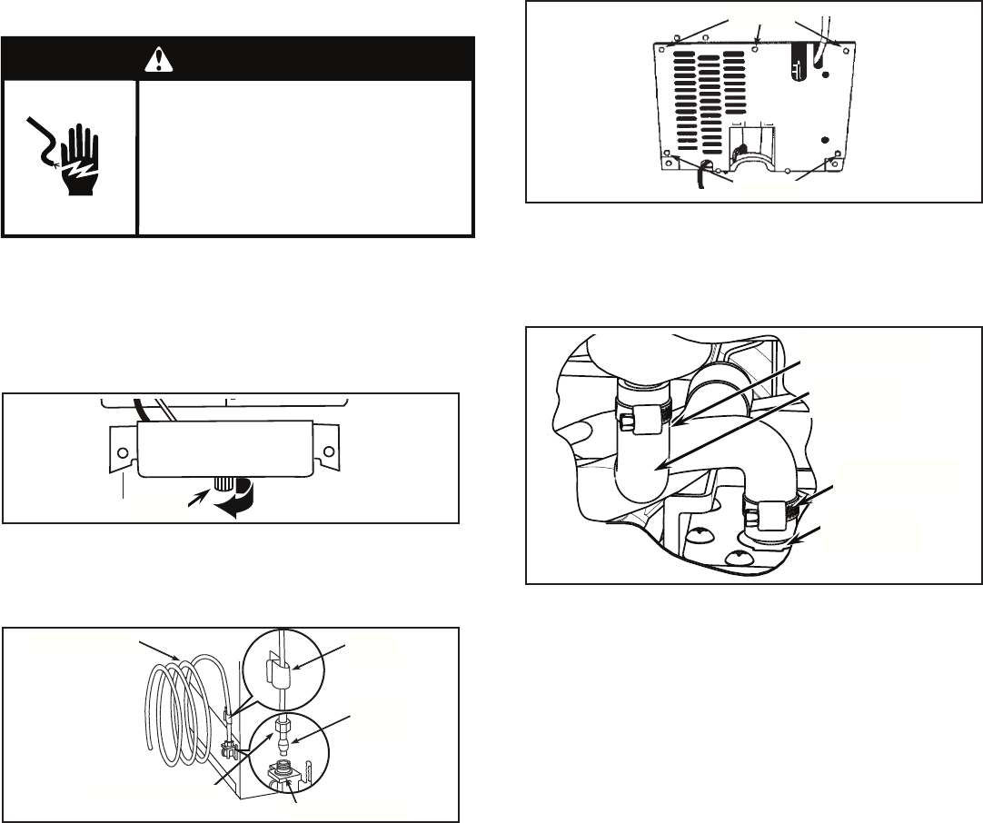
Installation Instructions
for Ice Maker Drain Pump
IMPORTANT: Connect drain pump to your drain in accordance with all state and local codes and ordinances. It may be desirable to insulate
drain tube thoroughly up to drain inlet to minimize condensation on the drain tube hose. Insulated tube kit part W10365792 is available
for purchase. Drain pump is designed to pump water to a maximum height of 10 feet.
Kit Contains:
(1) Drain Pump
(1) Drain Tube, 5/8” ID x 5-1/8” (ice maker bin to pump reservoir inlet)
(1) Drain Tube Hose, 1/2” ID x 10’ (pump discharge to household drain)
(1) Vent Tube, 5/16” ID x 32” (pump reservoir vent to ice maker cabinet back)
(3) Cable Clamp (secures vent tube to back of ice maker)
(5) Screws (secures pump to base plate and clamps to back of ice maker)
(1) Small Adjustable Hose Clamp, 5/8” (secures vent tube to pump)
(3) Large Adjustable Hose Clamps, 7/8” (secures drain tube to bin and drain pump reservoir inlet)
(2) Rear Panel
(1) Instruction Sheet
If Ice Maker is Presently Installed:
NOTE: If ice maker is not installed, proceed to Drain Pump
Installation section.
1. Push the selector switch to the OFF position.
2. Unplug ice maker or disconnect power.
3. Shut off water supply. Wait 5 to 10 minutes for the ice to fall
into the storage bin. Remove all ice from bin.
4. Unscrew the drain cap from the bottom of the water
pan located inside the storage bin. Allow water to drain
completely. Replace drain cap. See Figure 1.
WARNING
Electrical Shock Hazard
Disconnect power before servicing.
Failure to do so can result in death
or electrical shock.
Replace all parts and panels before
operating.
figure 1
DRAIN CAP
Instruction Sheet W10361742 Rev C 10/16
(continued on next page)
— 1 —
FERRULE
(SLEEVE)
figure 2
ICE MAKER CONNECTION
1/4” COMPRESSION NUT
1/4” COPPER TUBING CABLE
CLAMP
2. Remove old drain tube and clamp. Discard old drain tube
and clamp.
3. Install new drain tube to pump reservoir inlet using new
adjustable clamps. See Figure 4.
figure 3
SCREWS
SCREWS
figure 4
NEW 7/8” ADJUSTABLE
HOSE CLAMP INSTALLED
NEW DRAIN TUBE
(BIN TO PUMP)
NEW DRAIN PUMP
RESERVOIR INLET
NEW 7/8” ADJUSTABLE
HOSE CLAMP INSTALLED
5. If ice maker is built into cabinets, pull ice maker out of the
opening.
6. Disconnect water supply line. See Figure 2.
Drain Pump Installation:
1. Remove rear panel. See Figure 3 for ve (5) screw locations.
Pull old rear panel away from drain tube and discard panel
and save screws.
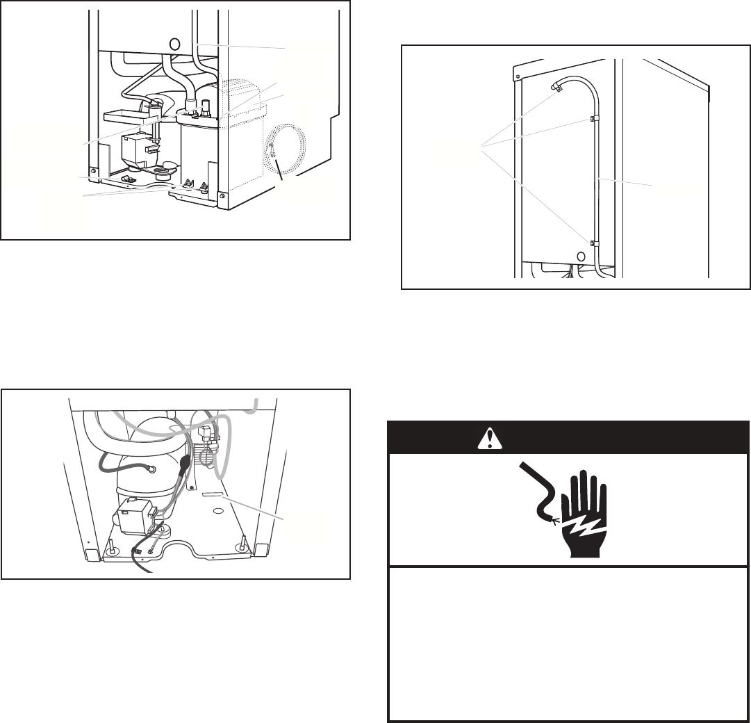
W10361742 C — 2 —
4. Install vent tube (5/16” x 32”) to pump reservoir vent. Use
5/8” adjustable clamp, supplied. See Figure 5.
NOTE: DO NOT install household drain tube at this time.
5. Remove power cord clamp and screw attached to ice maker
power cord. This is located at the unit base. See Figure 5.
Clamp and screw will be reused.
6. Slide drain pump into the ice maker base on the right side.
The pump mounting tab should slip into the rectangular slot
in the ice maker base. It will be necessary to tip the pump
slightly to slip into the slot. Figure 6 shows the mounting tab
that must slip into the slot.
7. Line up the two (2) screw holes at the rear of the pump. Use
two (2) of the screws supplied in kit. See Figure 5.
8. Connect drain tube to ice maker bin outlet (5/8” ID), using
7/8” adjustable clamp, supplied. See Figure 4.
9. Coil ice maker power cord into a 4” diameter coil. Wrap
electrical tape around the power cord in several places to
keep the cord in a coil. Locate coiled cord between the drain
pump and side of enclosure and plug into the receptacle of
the drain pump. See Figure 5.
10. Attach the drain pump power cord to ice maker unit base
with clamp and screw (removed in step 5) that was used to
attach ice maker power cord. See Figure 5.
11. Place new rear panel (small one for 15” ice makers, large
one for 18”) against the back of the ice maker. Route the vent
tube and drain pump discharge tube through cutouts in the
rear panel.
12. Secure rear panel with original screws. See Figure 3.
6
Rear Panel
3. Remove the old drain tube and clamp attached to the ice
maker bin.
NOTE: Discard old drain tube and clamp.
4. Install new drain tube (⁵⁄₈" I.D. x 5¹⁄₈") from ice maker bin to
drain pump reservoir inlet using new adjustable clamps. See
“Drain Tube” illustration.
NOTES:
■Do not kink.
■Trim tube length if required.
Drain Tube
5. Install vent tube (⁵⁄₁₆" I.D. x 32" [81 cm]) to drain pump
reservoir vent. Use one of the supplied ⁵⁄₈" small adjustable
clamp. See “Parts Locations” illustration.
NOTE: Do not install household drain tube at this time.
Parts Locations
6. Remove power cord clamp and ground screw attached to ice
maker power cord, which is mounted to the unit base. See
“Parts Locations” illustration.
NOTE: Clamp and screw will be reused.
7. Slide drain pump into the ice maker base on the right side.
The pump mounting tab should slip into the rectangular slot
in the ice maker base. It will be necessary to tip the pump
slightly to slip into the slot. See “Drain Pump Mounting Tab
Slot” illustration.
Drain Pump Mounting Tab Slot
Drain Pump Installed
A. Screw locations
A.
⁷⁄₈
" adjustable hose clamp
B. Drain tube (ice bin to drain pump)
C.
⁷⁄₈
" adjustable hose clamp
D. Drain pump reservoir inlet
A
A
A
B
C
D
A. Vent tube
B.
⁵⁄₈
" hose clamp
C. Drain pump discharge tube
D. Drain pump
E. Ice maker unit power cord
F. #8-32 x
³⁄₈
" pump
mounting screws
G. Drain pump power cord, clamp
and screw
A. Mounting tab slot
A. Drain pump installed
A
B
D
E
C
G
F
A
A
figure 6
MOUNTING
TAB SLOT
13. Secure vent tube to back of ice maker using three (3)
clamps and the three (3) remaining screws supplied in kit.
See Figure 7.
NOTE: Do not pinch, kink or damage the vent tube. Check that
it is not damaged or pinched or kinked between the cabinet and
the ice maker.
14. Attach 1/2” ID x 10’ drain tube to drain pump discharge tube.
See Figure 5.
15. Connect ice maker to water supply and install ice maker as
specied by the product installation instructions, supplied
with the product.
16. Check all connections for leaks.
17. Plug in ice maker or reconnect power.
18. Turn selector switch to ON.
19. Wait for rinsing cycle, approximately 5 minutes, to be sure
the ice maker is operating properly.
WARNING
Electrical Shock Hazard
Plug into a grounded 3 prong outlet.
Failure to follow these instructions can result in
death, fire, or electrical shock.
Do not use an extension cord.
Do not use an adapter.
Do not remove ground prong.
© Whirlpool Corporation 2016
(All Rights Reserved)
7
8. Align the 2 screw holes at the rear of the pump. Use two
#832 x ³⁄₈" screws, supplied. See “Parts Locations”
illustration.
9. Connect drain tube to ice maker bin outlet (⁵⁄₈" I.D.), using ⁷⁄₈"
adjustable clamp, supplied. See “Drain Tube” illustration.
10. Coil ice maker power cord into a 4" (10.2 cm) diameter coil.
Wrap electrical tape around the power cord in several places
to keep the cord in a coil. Locate coiled power cord between
the drain pump and side of enclosure and plug into the
receptacle of the drain pump. See “Parts Locations”
illustration.
11. Attach the drain pump power cord to ice maker unit base with
clamp and screw (removed in Step 6) that was used to attach
ice maker power cord. See “Parts Locations” illustration.
12. Place new rear panel (small one for 15" ice makers, large one
for 18") against the back of the ice maker. Route the vent
tube and drain pump discharge tube through cutouts in the
rear panel.
13. Secure rear panel with original screws. See “Rear Panel”
illustration.
14. Secure vent tube to back of ice maker using three clamps
and three #8-32 x ³⁄₈" screws, supplied. See “Vent Tube”
illustration.
Vent Tube
NOTE: Do not pinch, kink or damage the vent tube. Check that it
is not damaged or pinched or kinked between the cabinet and
the ice maker.
15. Attach ¹⁄₂" I.D. x 10 ft (3 m) drain tube to pump discharge
tube. See “Parts Locations” illustration.
NOTE: Do not connect outlet end of drain tube to a closed
pipe system to keep drain water from backing up into the ice
maker.
16. Connect ice maker to water supply and install ice maker as
specified by the product installation instructions.
17. Check all connections for leaks.
18. Plug in ice maker or reconnect power.
19. Turn on ice maker.
20. Wait for rinsing cycle, approximately 5 minutes, to be sure the
ice maker is operating properly.
Drain Connection
Gravity Drain System
Connect the ice maker drain to your drain in accordance with all
state and local codes and ordinances. If the ice maker is
provided with a gravity drain system, follow these guidelines
when installing drain lines. This will help keep water from flowing
back into the ice maker storage bin and potentially flowing onto
the floor, causing water damage.
■Drain lines must have a minimum of ⁵⁄₈" (15.88 mm) I.D.
(inside diameter).
■Drain lines must have a 1" drop per 48" (2.54 cm drop per
122 cm) of run or ¹⁄₄" drop per 12" (6.35 mm per 30.48 cm) of
run and must not have low points where water can settle.
■The floor drains must be large enough to accommodate
drainage from all drains.
■The ideal installation has a standpipe with a 1¹⁄₂" (3.81 cm) to
2" (5.08 cm) PVC drain reducer installed directly below the
outlet of the drain tube as shown. You must maintain a
1" (2.54 cm) air gap between the drain hose and the
standpipe.
■Do not connect the outlet end of the drain tube to a closed
pipe system to keep drain water from backing up into the ice
maker.
IMPORTANT: A drain pump is necessary when a floor drain is not
available. A Drain Pump kit, Part Number 1901A, is available for
purchase.
A. Vent tube
B. Clamps and screws
A
B
Electrical Shock Hazard
Plug into a grounded 3 prong outlet.
Do not remove ground prong.
Do not use an adapter.
Do not use an extension cord.
Failure to follow these instructions can result in death,
fire, or electrical shock.
WARNING
figure 7
CLAMPS AND
SCREWS
VENT TUBE
figure 5
6
Rear Panel
3. Remove the old drain tube and clamp attached to the ice
maker bin.
NOTE: Discard old drain tube and clamp.
4. Install new drain tube (⁵⁄₈" I.D. x 5¹⁄₈") from ice maker bin to
drain pump reservoir inlet using new adjustable clamps. See
“Drain Tube” illustration.
NOTES:
■Do not kink.
■Trim tube length if required.
Drain Tube
5. Install vent tube (⁵⁄₁₆" I.D. x 32" [81 cm]) to drain pump
reservoir vent. Use one of the supplied ⁵⁄₈" small adjustable
clamp. See “Parts Locations” illustration.
NOTE: Do not install household drain tube at this time.
Parts Locations
6. Remove power cord clamp and ground screw attached to ice
maker power cord, which is mounted to the unit base. See
“Parts Locations” illustration.
NOTE: Clamp and screw will be reused.
7. Slide drain pump into the ice maker base on the right side.
The pump mounting tab should slip into the rectangular slot
in the ice maker base. It will be necessary to tip the pump
slightly to slip into the slot. See “Drain Pump Mounting Tab
Slot” illustration.
Drain Pump Mounting Tab Slot
Drain Pump Installed
A. Screw locations
A.
⁷⁄₈
" adjustable hose clamp
B. Drain tube (ice bin to drain pump)
C.
⁷⁄₈
" adjustable hose clamp
D. Drain pump reservoir inlet
A
A
A
B
C
D
A. Vent tube
B.
⁵⁄₈
" hose clamp
C. Drain pump discharge tube
D. Drain pump
E. Ice maker unit power cord
F. #8-32 x
³⁄₈
" pump
mounting screws
G. Drain pump power cord, clamp
and screw
A. Mounting tab slot
A. Drain pump installed
A
B
D
E
C
G
F
A
A
VENT TUBE
DRAIN PUMP
DISCHARGE TUBE
(2) PUMP
MOUNTING
SCREWS
DRAIN PUMP
POWER CORD
CLAMP AND SCREW
SMALL (5/8”)
HOSE CLAMP
ICE MAKER
POWER CORD
