Whirlpool Super Capacity 465 Owners Manual Cover Pages
Wlp G&E Range Trng WLP G&E Range Trng WLP G&E Range Trng ranges may8 applianceservicesecretsmembership.com_manuals
Ja-4322089 Wlp G&E Range Trng JA-4322089 WLP G&E Range Trng JA-4322089 WLP G&E Range Trng Maytag, Magic Chef, Jenn Air applianceservicesecretsmembership.com_manuals
4322089 - Super Capacity 465 4322089 - Super Capacity 465 4322089 - Super Capacity 465 gasrange may8 applianceservicesecretsmembership.com_manuals
465 to the manual 3938eede-c5b7-4177-992a-883cfa54f61b
2014-08-26
: Whirlpool Whirlpool-Super-Capacity-465-Owners-Manual whirlpool-super-capacity-465-owners-manual whirlpool pdf
Open the PDF directly: View PDF ![]() .
.
Page Count: 32
CONSUMER SERVICES TECHNICAL
EDUCATION GROUP PRESENTS
JOB AID
Part No. 4322089
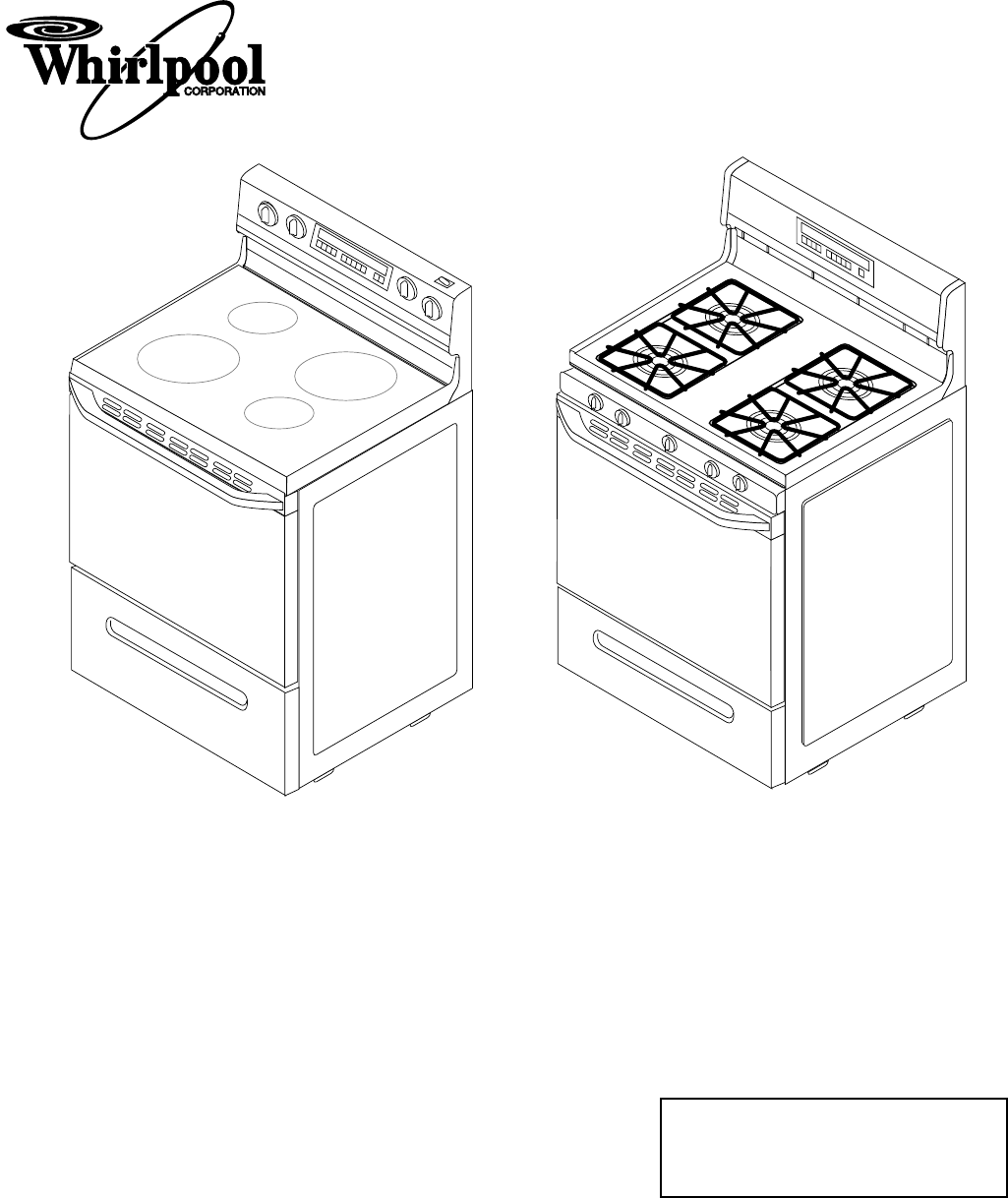
SUPER CAPACITY 465
FREESTANDING
GAS & ELECTRIC RANGES
Copyright 1996 Whirlpool Corporation
OBJECTIVE
The objective of this Job Aid is to have the experienced appliance technician become
familiar with the operation and service of the Whirlpool Ranges. It is designed as
reference material and is not a replacement for basic training.
FORWARD
This Job Aid will introduce the technician to the Whirlpool Ranges. This Job Aid is a
reference guide for the experienced technician. It is not designed as a replacement to
basic training. This Job Aid does not replace the Service Manual or the Use and Care
Guide. It is designed to be used in conjunction with these manuals.
WHIRLPOOL CORPORATION assumes no responsibility for any repair made on
our products by anyone other than Authorized Factory Service Technicians.
A-C-B-A-D-C-B-B-A-B
- 1 -
Table of Contents
Five Key Benefits & Features............................................................................................ Page 2
Warning Labels ................................................................................................................. Page 3
Model & Serial Number Location ...................................................................................... Page 4
Serial Number Description ................................................................................................ Page 4
Gas Range Model Number ............................................................................................... Page 5
Electric Range Model Number .......................................................................................... Page 5
Models With Electronic Controls ....................................................................................... Page 6
Oven Controls ................................................................................................................... Page 7
Using The Oven Controls .................................................................................................. Page 9
AccuSimmer™ Burner .................................................................................................... Page 10
The Venturi System.......................................................................................................... Page10
Gas Range Component Locations .................................................................................. Page 11
Oven Door Removal........................................................................................................ Page 12
Removing A Maintop ....................................................................................................... Page 13
L.P. Conversion............................................................................................................... Page 14
Orifice Specifications....................................................................................................... Page 14
Oven Door Lock System ................................................................................................. Page 16
Ignition System Operation ............................................................................................... Page 17
Typical Gas Range Wiring Diagram ................................................................................ Page 20
Gas Range Strip Circuits................................................................................................. Page 21
Oven Door Lock System Current Flow............................................................................ Page 22
The Oven Temperature Sensor ...................................................................................... Page 22
Electric Range Component Locations ............................................................................. Page 23
Oven Thermal Fuse Location .......................................................................................... Page 24
AccuBake™ Temperature Management System ............................................................ Page 24
Electric Range Wiring Diagram ....................................................................................... Page 25
Electric Range Strip Circuits ........................................................................................... Page 26
Confirmation Of Understanding....................................................................................... Page 27
- 2 -
FIVE KEY BENEFITS & FEATURES
1. The Largest Oven Capacity In The Industry
a) The Super Capacity 465™ Range offers more oven space than any other range in the
industry—
4.65 cubic feet
.
b) Large meals are never a problem with the spacious capacity.
c) Save time by cooking multiple meals and freezing them for the busy days ahead.
2. Consistent Cooking Results
a) AccuSimmer™ burners on gas ranges provide precise low-heating for delicate sauces and
chocolates (Models SF385 & SF395).
b) Food cooks evenly throughout the oven cavity.
c) Electronic controls maintain oven temperature swings within ±20˚F.
d) AccuBake™ Triple Cycling Elements on electric models with EZ-Touch 200 & EZ-Touch
300 oven controls.
e) Custom Broil allows the selection of temperature from 300˚F to 525˚F (300˚F to 500˚F on
electric ranges) so that everything from fish to steaks broil perfectly (on all Touch Control
models).
3. Easy-To-Use Controls
a) Whirlpool EZ-Touch™ Electronic Controls offer the following innovative features:
• One-Touch operation sets Bake at 350˚F, and Self-Clean for 3.5 hours.
• Exclusive Preheat Countdown visually indicates the time required for oven preheating.
The oven control beeps when the preset temperature is reached.
• Child Lockout disables the control panel to prevent children from accidentally turning the
oven on.
• Easy to understand left-to-right programming logic.
• Color-Keyed touch pads.
4. Easy To Clean
a) Spillguard™ Cooktop has raised edges to help contain spills. Porcelain surfaces wipe
clean with a damp sponge.
b) CleanTop™ Ranges offer radiant elements under a one-piece, smooth ceramic glass
surface for easy clean up.
c) Seamless cooktop on coil ranges lifts easily for cleaning the burner box.
d) Automatic door lock for self-clean ovens requires no external latch to lock the oven door
for the Self-Clean cycle.
5. Modern Design
a) Stylish cabinet depth design offers a built-in look.
b) A modern curved console and a one-piece solid handle are designed with no exposed
screws or unsightly trim.
c) A hidden vent.
d) 200-degree rotation infinite flame setting valves on gas ranges (SF385 & SF395) offer
optional ergonomic, one-turn operation, while allowing precise burner management.
e) Whirlpool “Family Look” styling compliments an entire kitchen of Whirlpool appliances.
- 3 -
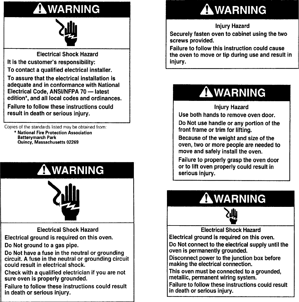
WARNING LABELS
This manual is intended for factory-service technicians only. We recommend that customers DO NOT
service their own units, because of the complexity and risk of high-voltage electrical shock.
The following information is used throughout this manual, and should be read carefully.
- 4 -
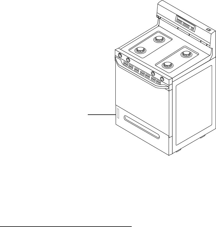
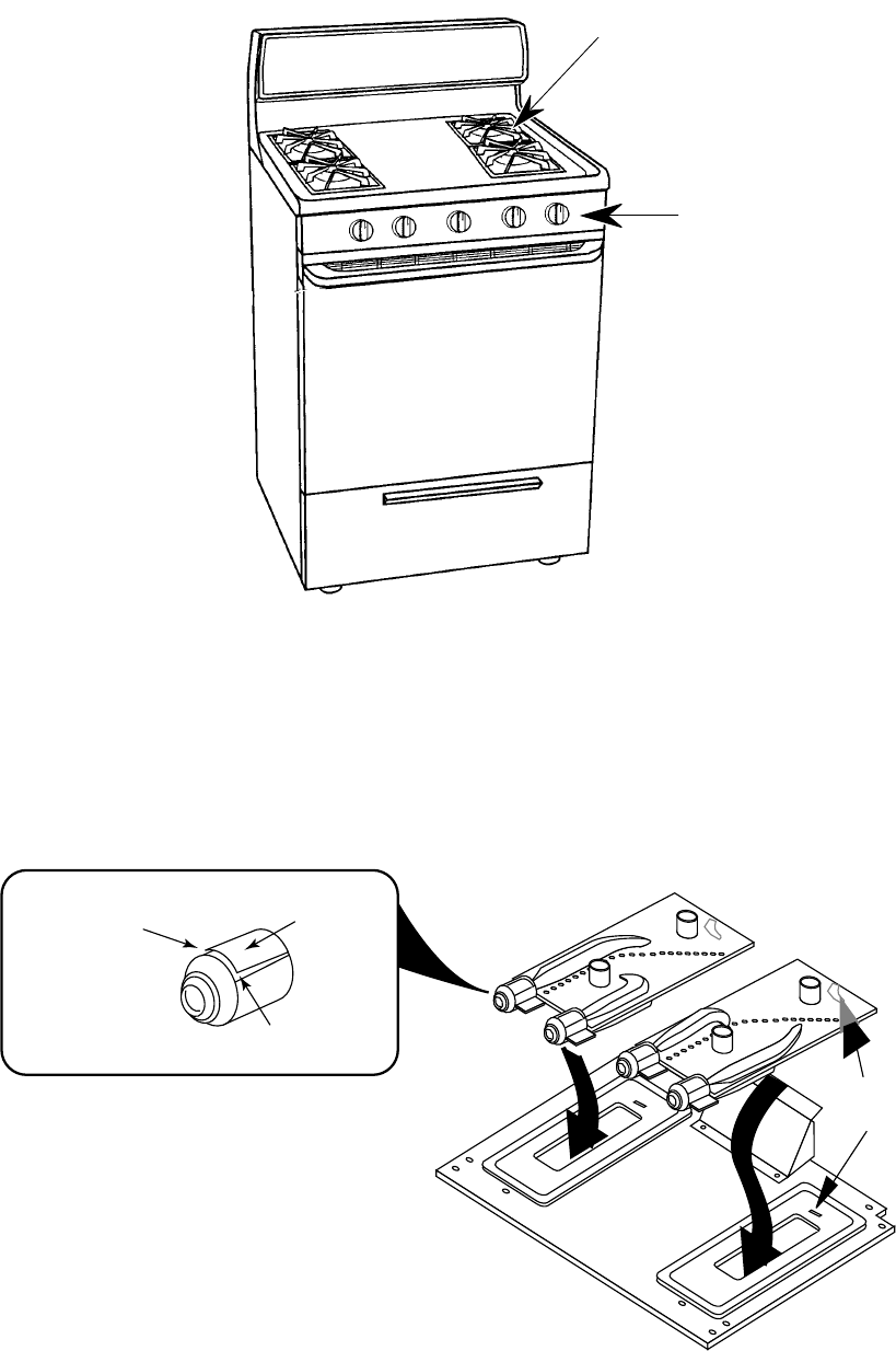
MODEL & SERIAL NUMBER LOCATION
The Model/Serial Number Plate is located behind the broiler/storage drawer.
Model/Serial Plate
The serial number can be decoded by using the following example:
SERIAL NUMBER: RF 36 50001
R = Manufacturing Location (Tulsa, OK)
F = Year of Manufacture (1996)
36 = Week of Production (36th week)
50001 = Sequence of Range
SERIAL NUMBER DESCRIPTION

- 5 -
GAS RANGE MODEL NUMBER
MODEL NUMBER =
R = ELECTRIC
F = FREESTANDING
3 = 30" RANGE
0-2 = STANDARD CLEAN
4-9 = SELF-CLEAN
0, 2, 5 = COIL ELEMENTS
4 = STANDARD PATTERN CERAMIC
6 = DELUXE PATTERN CERAMIC
B = GLASS DOOR L = LARGE WINDOW
P = STANDARD WINDOW O = STEEL DOOR
X = ENGINEERING DIGIT
YEAR OF INTRODUCTION
E = 1996
W = WHITE Q = WHITE-ON-WHITE B = BLACK-ON-BLACK
N = ALMOND Z = ALMOND-ON-ALMOND
R F 3 8 6 P X E Q
ELECTRIC RANGE MODEL NUMBER
MODEL NUMBER =
S = GAS
F = FREESTANDING
3 = 30" RANGE
0-2 = STANDARD CLEAN
4-9 = SELF-CLEAN
2 = OPEN BURNER
4 = OPEN BURNER
5 = SEALED BURNER
B = GLASS DOOR L = LARGE WINDOW
P = OPEN BURNER O = STEEL DOOR
S = PILOT IGNITION
E = ELECTRIC IGNITION
YEAR OF INTRODUCTION
E = 1996
W = WHITE Q = WHITE-ON-WHITE B = BLACK-ON-BLACK
N = ALMOND Z = ALMOND-ON-ALMOND
S F 3 9 5 L E E Q

- 6 -
MODELS WITH ELECTRONIC CONTROLS
Gas Ranges
The following chart shows the gas range models with electronic controls:
OVEN CONTROL WHIRLPOOL ROPER ESTATE
K.E.T. SF350BEE** FGS335E**
EZ-100 SF360BEE**
EZ-150
SF315PEE
TGS325E**SF372BEE**
SF375BEE**
EZ-200
SF325PEE
SF385PEE**
EZ-300 SF395LEE**
** Self-Clean Model
** Self-Clean Model
OVEN CONTROL WHIRLPOOL ROPER ESTATE
K.E.T.
RF350PXE** FES330E**
RF354BXE** FES364E
EZ-100
RF360BXE**
TES325E**
RF364BXE**
RF375BXE**
EZ-150
RF315PXE**
RF372BXE**
RF375PXE**
RF376PXE**
EZ-200
RF324PXE
RF325PXE
RF385PXE**
RF386PXE**
EZ-300
RF395LXE**
RF396LXE**
Electric Ranges
The following chart shows the electric range models with electronic controls:
- 7 -
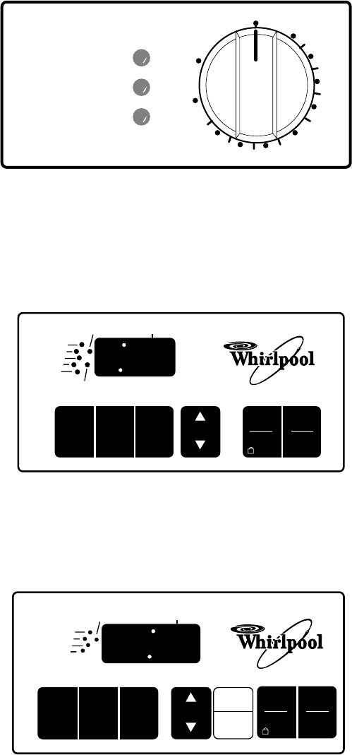
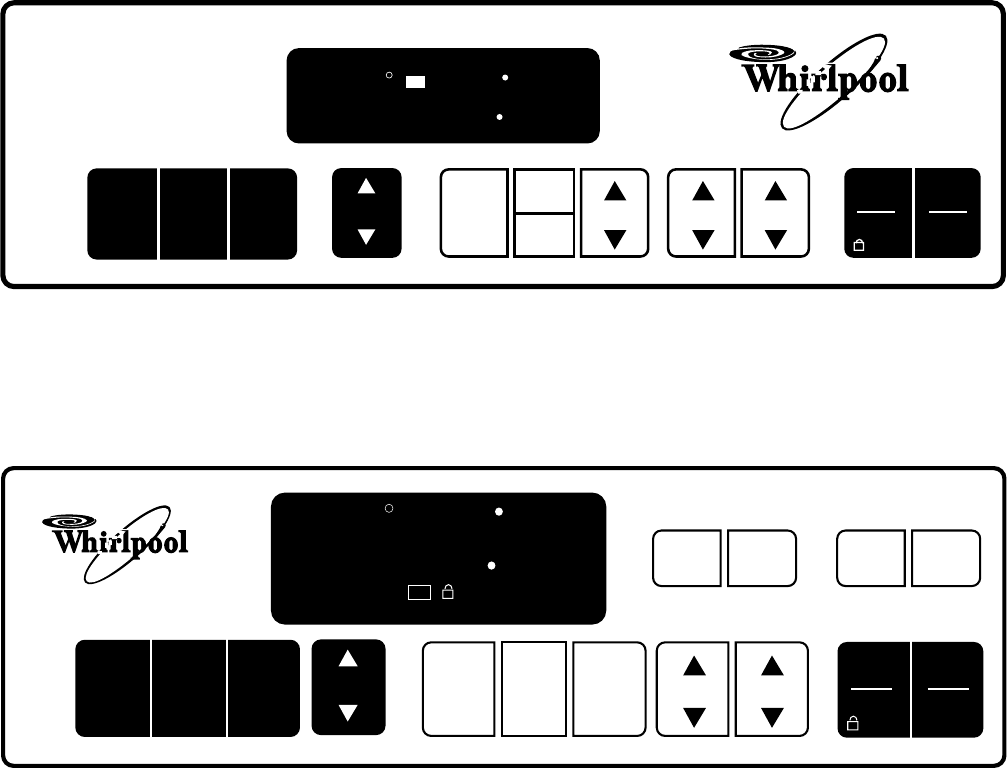
OVEN CONTROLS
The Super Capacity 465 ranges use one of the following five electronic controls:
K.E.T. Single-Knob Control
(Knob With Electronic Thermostat)
This oven control includes: Bake Temperature settings with Broil and
Clean, Oven On, Oven Heating, & Door Locked/Cleaning indicators
OFF
WARM
200
250
300
350
400
450
500
BROIL
CLEAN
Push To
Turn
Push To
Turn
OVEN ON
(TURN OFF OVEN WHEN FLASHING)
OVEN HEATING
DOOR LOCKED/CLEANING
(CLOSE DOOR WHEN FLASHING)
BAKE CUSTOM
BROIL AUTO
CLEAN
CLOCK
TIMER
.. CANCEL
TEMP/
TIME
START
ENTER
5 SEC
OFF
ON
TIMER
CANCEL
88 88
BAKE
BROIL
HEAT
START ?
EZ-Touch™ 150
Adds a Time-Of-Day Clock, Color-Keyed Temperature and Clock/Timer
Pads, Electronic Minute Timer and Signal.
BAKE CUSTOM
BROIL AUTO
CLEAN TEMP START
ENTER
5 SEC
OFF
ON
CLOSE DOOR
DOOR LOCKED
CANCEL
SELF-CLEANING OVEN
8 88
BAKE
BROIL
CLEAN
PREHEAT
START ?
EZ-Touch™ 100
This oven control offers an electronic LED Display, Indicator Lights,
Custom Broil, Auto Clean, Child Lockout, and Start Prompt (no Time-
Of-Day function).
- 8 -
EZ-Touch™ 200
BAKE CUSTOM
BROIL AUTO
CLEAN
TEMP HR MINMIN
START
ENTER
5 SEC
OFF
CANCEL
88 88
888
ON
HEAT BAKE BROIL LOCKD CLEAN TEMP
SELF-CLEANING OVEN
TIMER
SET
CLOCK
TIMER
OFF
Adds an Illuminated Vacuum Fluorescent Display, AccuBake Tempera-
ture Management System, Separate Time/Temp Displays, and Inte-
grated Light Touch Pad.
EZ-Touch™ 300
Adds Delay Cook and Off functions.
BAKE CUSTOM
BROIL AUTO
CLEAN
TEMP HR MIN
CLOCK LIGHT
TIMER
SET TIMER
OFF
START
ENTER
5 SEC
OFF
CANCEL
88 88
888
ON
HEAT
DELAY
TIMED
TIMER
LOCKED
COOK
STOP
CLEAN
TIME
BAKE
BROIL START ?
C
F
SELF-CLEANING OVEN
DELAY
START
TIME
COOK
TIME STOP
TIME
- 9 -
USING THE OVEN CONTROLS
To set the various oven control functions, use the following procedures:
ELECTRONIC TIME-OF-DAY CLOCK
• Press CLOCK.
• Press TEMP.
• Press START.
ELECTRONIC MINUTE TIMER AND SIGNAL
• Press TIMER.
• Press TEMP.
• Press START.
• To cancel or turn off the Timer, press
TIMER twice.
TO USE COOK TIME
• Press COOK TIME.
• Press HR & MIN.
• Press START.
TO USE STOP TIME
• Press STOP TIME.
• Press HR & MIN.
• Press START.
TO USE COOK TIME AND DELAY START TIME
• Press COOK TIME.
• Press HR & MIN.
• Press START.
• Press STOP TIME.
• Press HR & MIN.
• Press START.
START PROMPT
• Press START to begin the selected func-
tion.
CHILD LOCKOUT
• Press and hold START for 5 seconds.
TEMPERATURE ADJUSTMENT
• Press and hold BAKE for 4 seconds.
• Press TEMP UP or DOWN arrow.
• Press START.
FAHRENHEIT/CELSIUS CONVERSION
• Press and hold the CUSTOM BROIL for 5
seconds.
ADJUSTABLE AUDIBLE SIGNAL
• Press and hold STOP TIME for 5 sec-
onds.
CLOCK DISABLE
• Press and hold CLOCK for 5 seconds.
DEMO FEATURE
• Press and hold TIMER SET for 5 seconds.
PREHEAT COUNTDOWN TIMER AND SIGNAL
• Press BAKE.
• Press START.
CUSTOM BROIL
• Press CUSTOM BROIL
• Press TEMP.
• Press START.
SELF-CLEAN COUNTDOWN TIMER
• Press AUTO CLEAN.
• Press START.
CANCEL OR STOP
• Press CANCEL.
- 10 -
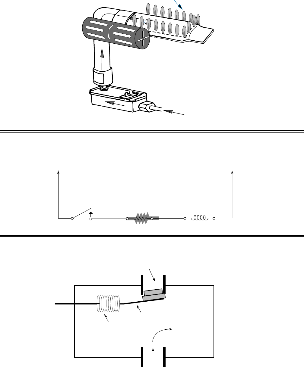
ACCUSIMMER™ BURNER
The exclusive sealed gas venturi burners provide precise, even flame control so that each burner
stays lit, even under sudden draft conditions. Airflow to the front and rear burners is adjusted at the
front of the venturi by prying the slots open or closed, or by rotating the air shutters.
BURNER
BOX
INSERT TAB
INTO SLOT
VENTURI
OPENING
VENT
PRY VENT
UP OR
DOWN
THE VENTURI SYSTEM
The AccuSimmer™ (right rear) burner is designed to provide 550 B.T.U.s for precise, low-heat
cooking.
ACCUSIMMER
BURNER
CONTROL
ACCUSIMMER
BURNER
- 11 -
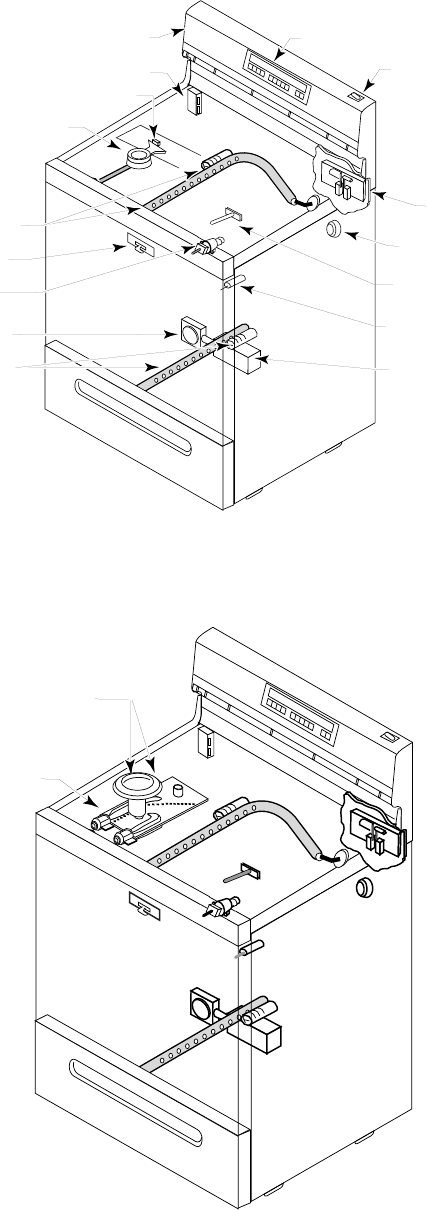
GAS RANGE COMPONENT LOCATIONS
Conventional Burners
CONSOLE
CONVENTIONAL
BURNER
DOOR LATCH
GAS VALVE
& SPARK IGNITOR
SWITCH
MANUAL OVEN
LIGHT SWITCH
GAS SAFETY
VALVE
AUTOMATIC OVEN
LIGHT SWITCH
OVEN LIGHT
LATCH SENSING
SWITCHES & DOOR
LATCH SOLENOID
TEMPERATURE SENSOR
OVEN CONTROL
IGNITOR MODULE
BURNER IGNITOR
PRESSURE
REGULATOR
BROIL BURNER
& IGNITOR
BAKE BURNER
& IGNITOR
SEALED BURNER
& BURNER IGNITOR
VENTURI
Sealed Burners
- 12 -
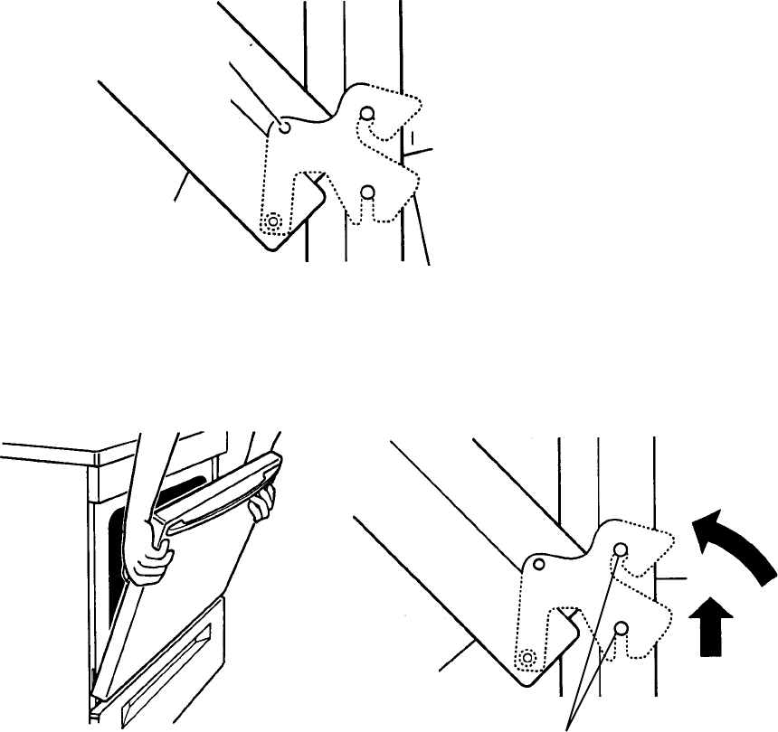
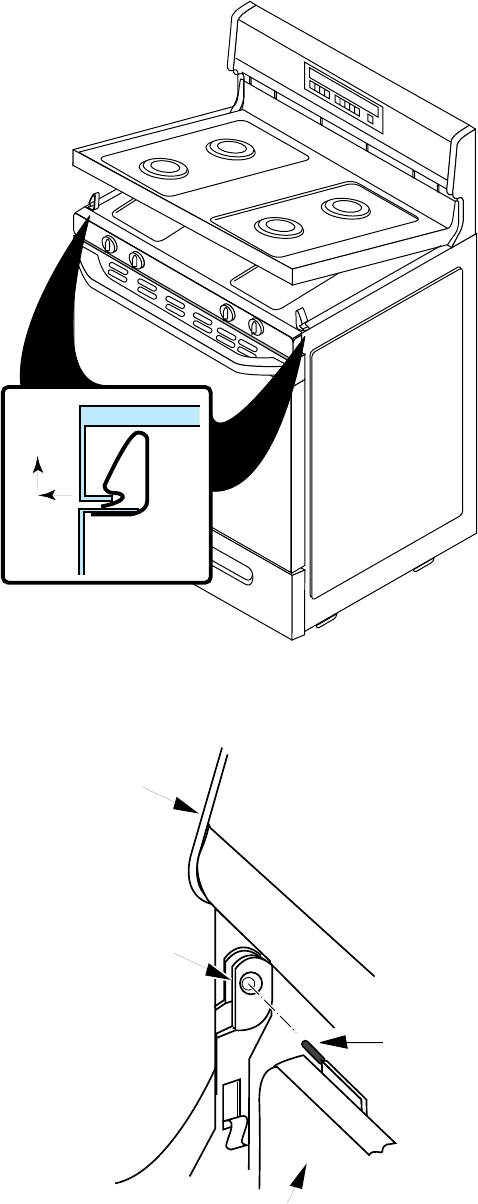
OVEN DOOR REMOVAL
insert nail or
screw here
range
hinge hanger
oven door
oven door
range
LIFT
ROTATE
hinge pins
2. Close the oven door as far as the nails or screws will allow, lift the door off the two
hinge pins, pull the door towards you so that the hinges are free of the slots, and
remove it.
The procedure for removing the oven door is the same for both gas and electric ranges. The door
removal is different from previous ranges. To remove the door:
1. Open the door half way and install a nail or a screw into the hinge hanger holes on
both sides of the door.
- 13 -
REMOVING A MAINTOP
1. Push the front of the maintop to the left and lift the left corner, then unclip and lift the
other corner, and raise the front of the maintop.
PUSH TO
SIDE AND
LIFT TO
UNCLIP
CLIP
MAINTOP
SIDE PANEL
HINGE
BRACKET
HINGE PIN
UPPER
CONSOLE
MAINTOP
2, Slide the maintop to the right and remove the left hinge pin from the hinge bracket,
then free the right hinge pin from its bracket, and remove the maintop.
- 14 -
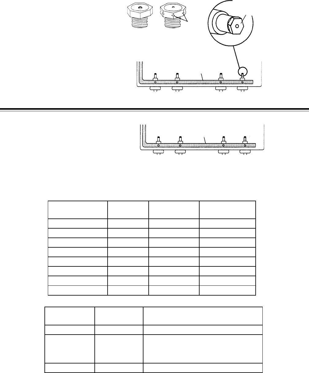
L.P. CONVERSION
L.P. Conversion Kits will be shipped with the product. Kits include four top burner orifice spuds. The
kit numbers are as follows:
Kit #3196473—Sealed Burner Models
• (2) #65 spuds–8500 B.T.U. (brass)
• (1) #68 spud–6500 B.T.U. (black)
• (1) .7 mm spud–5500 B.T.U. (nickel) notches
L.P.
Natural
L.R.
7500
L.F.
9500
R.F.
9500
R.R.
6500
brass nickel
brassblack
manifold
Remove & replace orifice
spuds with the same color
spuds
Kit #3196471—Open Burner Models
• (4) #66 spuds (8000 B.T.U. each).
brass brass
brassbrass
R.R.
9000
L.F.
9000
L.R.
9000
R.F.
9000
manifold
SUGGESTED
DRILL SIZE
1.45 MM
NO. 65
NO. 55
NO. 68
1.2 MM
.7 MM
NO. 54
NO. 66
COLOR
BRASS
BRASS
BLACK
BLACK
NICKEL
NICKEL
BRASS
BRASS
STAMPING
NAT
L.P.
NAT
L.P.
NAT
L.P.
NAT
L.P.
BTU RATING
9,500
8,500
7,500
6,500
6,500
5,500
9,000
8,000
SPUD KIT
NUMBER
3196471
3196473
3196474
SPUD #
& QTY.
3196211 (4)
3196450 (2)
3196335 (1)
3196336 (1)
3196643 (4)
DESCRIPTION
L.P. Conversion (Open Burner)
L.P. Conversion (Sealed Burner)
Nat. Gas Spud Kit (Open Burner)
ORIFICE SPECIFICATIONS
- 15 -
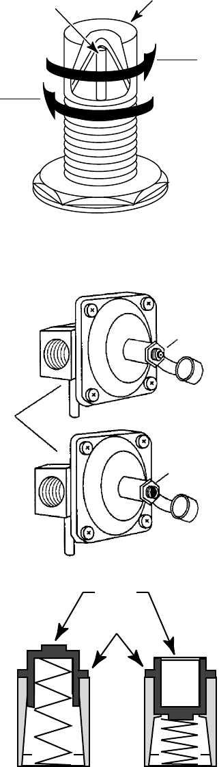
Reverse the regulator cap so that
LP
faces up.
L.P. CONVERSION
Turn the orifice hoods on the oven burner(s) down 2-1/2 - turns.
L.P. GAS:
DECREASES GAS
AND FLAME SIZE
IN THIS DIRECTION
NATURAL GAS:
INCREASES GAS
AND FLAME SIZE
IN THIS DIRECTION
HOOD
PIN
Regulator
L.P. Gas
Natural Gas
L.P. GAS
NATURAL GAS
WASHER
CAP
- 16 -
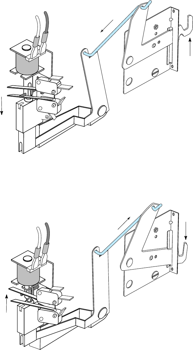
OVEN DOOR LOCK SYSTEM
LATCH IS
UP AND
DOOR IS
LOCKED
SOLENOID
PLUNGER IS
EXTENDED
ACTUATOR ROD
The oven door lock system uses a solenoid-activated, push-push mechanism. The oven door will
lock as soon as it is closed and the CLEAN function is programmed into the Electronic Oven Control
(EOC). When the solenoid is activated, the plunger extends, and the actuator rod moves the latch
to lock the door.
After the CLEAN cycle is completed and the temperature inside the oven cavity falls below 500˚F,
the latch solenoid relay closes and activates the door lock solenoid. The solenoid plunger retracts,
and actuator rod pulls the latch and unlocks the oven door.
LATCH IS
DOWN AND
DOOR IS
UNLOCKED
ACTUATOR ROD
SOLENOID
PLUNGER IS
RETRACTED
- 17 -
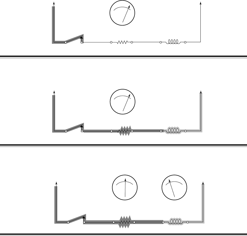
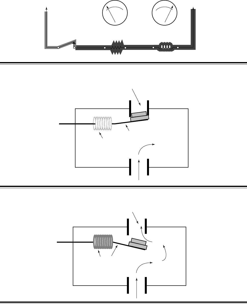
IGNITION SYSTEM OPERATION
OHMS LAW:
I = E/R
AMPS = VOLTAGE DIVIDED BY RESISTANCE
A cold ignitor has a high resistance. When the oven control relay closes—
IGNITOR
OVEN CONTROL
RELAY BIMETAL
COIL
NL1
LO HI
OHMS
Current flows through the ignitor and the bimetal coil.
IGNITOR
OVEN CONTROL
RELAY BIMETAL
COIL
NL1
LO HI
OHMS
High ignitor resistance causes low current flow through the bimetal coil. As the ignitor heats up, its
resistance decreases.
IGNITOR
OVEN CONTROL
RELAY BIMETAL
COIL
NL1 LO HI
OHMS
LO HI
AMPS
- 18 -
Lower ignitor resistance increases the current flow through the bimetal coil. When the ignitor is fully
heated, its resistance is low. Low resistance causes maximum current to flow through the bimetal
coil (2.5 to 3.6 amps).
IGNITOR
OVEN CONTROL
RELAY BIMETAL
COIL
NL1 LO HI
OHMS
LO HI
AMPS
As the bimetal coil heats, it heats the bimetal arm inside the gas safety valve.
BIMETAL ARM
GAS OUTLET
VALVE CLOSED
GAS INLET
BIMETAL
COIL HEATS
LOW
CURRENT
FLOW
(IGNITOR
IS COLD)
As the bimetal arm heats, it bends and opens the gas safety valve outlet to the burner.
GAS OUTLET
VALVE OPEN
GAS INLET
BIMETAL
COIL HEATS
& BENDS ARM
HIGH
CURRENT
FLOW
(IGNITOR
IS HOT)
- 19 -
The gas at the burner is lit by the hot ignitor and a flame is produced.
When the oven reaches its selected temperature, the oven control relay opens, and power is
removed from the circuit. With no voltage applied, the ignitor and bimetal coil start to cool.
IGNITOR
OVEN CONTROL
RELAY BIMETAL
COIL
NL1
The bimetal arm cools, bends to its original position, and closes the gas safety valve.
The burner flame is extinguished.
BIMETAL ARM
GAS OUTLET
VALVE CLOSED
GAS INLET
BIMETAL COIL
HOT
IGNITOR
BURNER
BURNER
FLAME
GAS VALVE
GAS FLOW
- 20 -
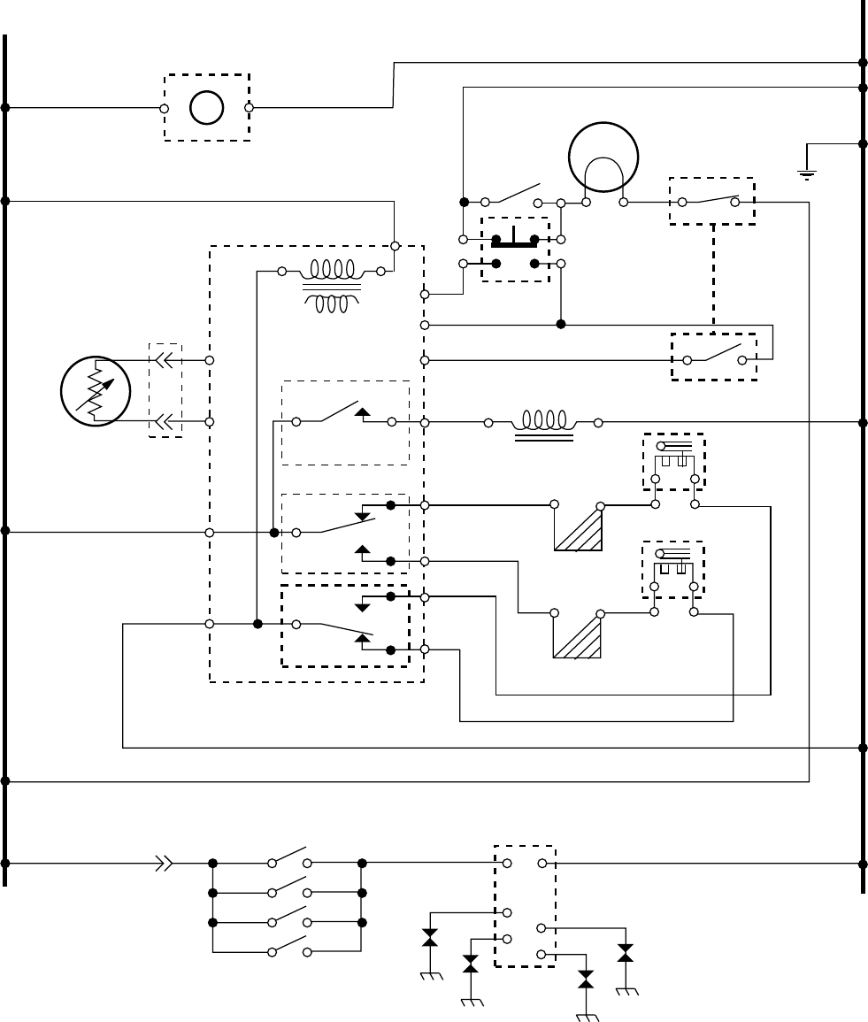
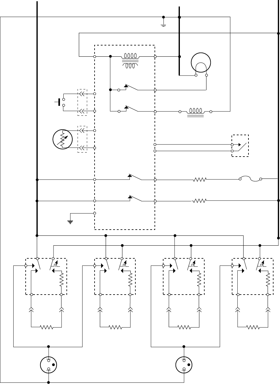
TYPICAL GAS RANGE WIRING DIAGRAM
K.E.T., EZ-100 & EZ-150 Controls
L1
N
BK
BK
V
V
W
W
W
BU
BU
RR
BR
BU
GY
Y
Y
WW
W
W
W
BK BK
BK
BK
OVEN
TEMP
SENSOR
OVEN CONTROL
TRANSFORMER
P5
P1-1
P1-5
P1-3
P4
P1-6
P1-7
P3-1
P2-1
P3-4
P3-2
P2-4
P2-2
LATCH SOLENOID
RELAY
BROIL
RELAY
BAKE
RELAY
LATCH
SOLENOID DOOR
LATCH SW.
DOOR
LATCH SW.
BAKE VALVE
BROIL VALVE
BAKE IGNITOR
BROIL IGNITOR
IGNITOR MODULE
DOOR
LIGHT SW.
OVEN LIGHT
TIMER
(IF EQUIPPED)
MANUAL
OVEN LIGHT
SWITCH
(IF EQUIPPED)
GND
N.O.
N.O.
SURFACE BURNER
IGNITOR SWITCHES
- 21 -
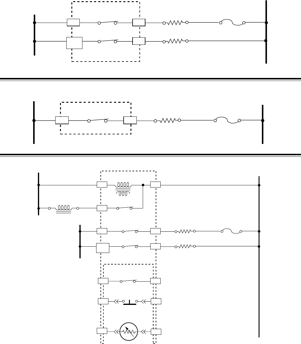
GAS RANGE STRIP CIRCUITS
K.E.T., EZ-100 & EZ-150 Controls
L1 N
WBK
BK RW
VV
OVEN CONTROL
OVEN CONTROL
TRANSFORMER
SENSOR
BAKE RELAY
BAKE VALVE
BAKE IGNITOR
BROIL RELAY
P3-4P3-1
P1-6 P1-7
P5 P2-1
P2-4
SELF-CLEAN CIRCUIT
L1 N
WBK
BK BU
BR
BU GY
GYY
W
W
VV
OVEN CONTROL
OVEN CONTROL
TRANSFORMER
SENSOR
BAKE RELAY
BAKE VALVE
BAKE IGNITOR
BROIL RELAY
LATCH RELAY*
P3-4
P4
P3-1
P1-6
(N.O.)
DOOR
SWITCH
DOOR LATCH
SWITCH
LATCH
SOLENOID
P1-5P1-1
P1-3
P1-7
* PULSE 1 SECOND
P5 P2-1
P2-4
L1 N
WBK
BK BU W
VV
OVEN CONTROL
OVEN CONTROL
TRANSFORMER
SENSOR
BAKE RELAY
BROIL VALVE
BROIL IGNITOR
BROIL RELAY
P3-2P3-1
P1-6 P1-7
P5 P2-1
P2-2
BROIL CIRCUIT
BAKE CIRCUIT
- 22 -
OVEN DOOR LOCK SYSTEM
CURRENT FLOW
Voltage is supplied to the control transformer whenever the range is plugged in. Current flows from
L1, through the transformer, to the neutral side of the line. When voltage is supplied to the EOCs
Latch Solenoid Relay, current flows through the Latch Solenoid, to the neutral side of the line.
L1 N
W
BK
BK BU
BR
BU GY
GYY
W
W
VV
OVEN CONTROL
OVEN CONTROL
TRANSFORMER
SENSOR
BAKE RELAY
BAKE VALVE
BAKE IGNITOR
BROIL RELAY
LATCH RELAY
P3-4
P4
P3-1
P1-6
(N.O.)
DOOR
SWITCH
DOOR LATCH
SWITCH
LATCH
SOLENOID
P1-5P1-1
P1-3
P1-7
* PULSE 1 SECOND
P5 P2-1
P2-4
THE OVEN TEMPERATURE SENSOR
The oven temperature sensor is a “Resistance Temperature Detector” (RTD), and is composed
of a stainless steel tube with a thin film of platinum at the end. It is located at the upper left rear corner
of the oven cavity. The RTD is a nonadjustable assembly, but may be checked at room
temperature, or at 350˚F. A sensor resistance of less than 550 ohms is regarded as a shorted
sensor, and a resistance greater than 3000 ohms is regarded as an open sensor. When the oven
control senses a resistance of less than 550 ohms, and greater than 3000 ohms, the bake and broil
functions will be turned off.
To test the oven temperature sensor, perform the
following steps:
1. Use an ohmmeter and set the range switch to
R x 10.
2. With no power applied, touch the leads of the
ohmmeter to the connector pins of the sensor
(you do not have to separate the connectors).
Depending upon the oven temperature, you
should obtain the corresponding reading
shown in the chart:
Temperature (˚F) Resistance (Ω)
32 ± 1.9 1000 ± 4.0
75 ± 2.5 1091 ± 5.3
250 ± 4.4 1453 ± 8.9
350 ± 5.4 1654 ± 10.8
450 ± 6.9 1853 ± 13.5
550 ± 8.2 2047 ± 15.8
650 ± 8.6 2237 ± 18.5
900 ± 13.6 2697 ± 24.4
- 23 -
ELECTRIC RANGE COMPONENT
LOCATIONS
OPEN COIL
ELEMENT
HOT SURFACE
INDICATOR
(CERAN GLASS
MAINTOP)
BROIL ELEMENT
ELECTRONIC
OVEN CONTROL
OR MECHANICAL OVEN
THERMOSTAT
SURFACE
ELEMENT CONTROL
SURFACE ELEMENT
(CERAN GLASS MAINTOP)
BAKE ELEMENT
OVEN TEMP SENSOR*
THERMO-BULB**
AUTOMATIC
OVEN LIGHT
SWITCH
OVEN LIGHT
MANUAL
OVEN LIGHT
SWITCH
(SOME MODELS)
OVEN
THERMAL FUSE
• For a description and test procedure for the Oven Temperature Sensor, refer to the previous page.
- 24 -
OVEN THERMAL FUSE
Electric (Pyro) Gas (Pyro) Electric (Non-Pyro) Gas (Non-Pyro)
Bake Preheat Time &
Temperature Ranges
170˚ - 245˚
2 min. 30 sec.
250˚ - 445˚
4 min. 15 sec.
450˚ - 500˚
6 min. 30 sec.
170˚ - 245˚
4 min.
250˚ - 445˚
10 min.
450˚ - 500˚
15 min.
170˚ - 245˚
2 min. 30 sec.
250˚ - 445˚
4 min. 15 sec.
450˚ - 500˚
6 min. 30 sec.
170˚ - 245˚
4 min.
250˚ - 445˚
10 min.
450˚ - 500˚
15 min.
Bake Preheat Relay
“ON” Time
Bake % = 100
Broil % = 40 Bake % = 100 Bake % = 100
Broil % = 40 Bake % = 100
Bake Relay “ON” Time Bake % = 60
Broil % = 20 Bake % = 100 Bake % = 60
Broil % = 20 Bake % = 100
Broil Relay “ON” Time Broil % = 100 Broil % = 100 Broil % = 100 Broil % = 100
Clean Preheat Relay
“ON” Time
Bake % = 60
Broil % = 40 N.A. N.A. N.A.
Clean Relay “ON” Time Bake % = 80
Broil % = 70 Bake % = 100 N.A. N.A.
BROIL ELEMENT
TERMINALS
THERMAL
FUSE
BACK OF OVEN
The oven thermal fuse is located on the back of the range. A thermal fuse is used on electric models
with EZ-200 and EZ-300 oven controls.
Relay Cycling Chart
The AccuBake™ Temperature Management System provides better baking results. Both the Bake
and Broil elements can cycle independently or together to maintain more even temperatures.
The following “Relay Cycling Chart” shows how the relays operate the two elements to obtain
various bake and broil temperatures.
ACCUBAKE™ TEMPERATURE
MANAGEMENT SYSTEM
- 25 -
ELECTRIC RANGE WIRING DIAGRAM
EZ-200 & EZ-300 Oven Controls
L1 L2
N
BK
BK
BK
V
Y
Y
V
BU
BU BU
BU-W
R
R
W
R
R
BR
W
W
W
W
BK
BK
G
L1
P
H1
OR OR
H2
L2
GND
OVEN CONTROL
LF
TRANSFORMER
P3-3
P4-3 P4-1
P4-4
P4-5
P3-4
P3-6
P3-7
P2-2
P2-3
OR P6
P3-5
P2-1
P2-4
LATCH SOLENOID
RELAY
DOOR LOCK
SOLENOID
BROIL ELEMENT
BAKE ELEMENT
SURFACE
INDICATOR
LIGHT
SURFACE
INDICATOR
LIGHT
OVEN LIGHT
GND
OVEN LIGHT
RELAY
BAKE RELAY
BROIL RELAY
BU
BU
P3-1
P3-2
DOOR
LATCH SW.
DOOR
SW.
OVEN TEMP
SENSOR
N.O.
COM
2600 W
22Ω
L1
P
H1
YY
H2
L2
LR
1500 W
38Ω
L1
P
H1
BR BR
H2
L2
RF
1500 W
38Ω
L1
P
H1
BU BU
H2
L2
RR
2600 W
22Ω
3400W
2400W
R
R
R
THERMAL FUSE
OPENS @
184˚C
- 26 -
ELECTRIC RANGE STRIP CIRCUITS
EZ-200 & EZ-300 Oven Controls
L1
L2
BK
BK RR
BROIL ELEMENT
BAKE ELEMENT
BU BU-W R
THERMAL FUSE
OPENS @ 184˚C
BROIL
RELAY
OVEN CONTROL
BAKE
RELAY
P2-2 P2-1
P2-4
P2-3
OR P6
BAKE CIRCUIT
L1 L2
BK
BROIL ELEMENT
BU BU-W R
THERMAL FUSE
OPENS @ 184˚C
BROIL
RELAY
OVEN CONTROL
P2-2 P2-1
BROIL CIRCUIT
DOOR LATCH
SWITCH
DOOR
SWITCH
L1
L2
N
BK
BK
Y
Y
RR
R
BR
W
W
OVEN CONTROL
TRANSFORMER
BROIL ELEMENT
BAKE ELEMENT
LATCH RELAY
BU
BU BU
BU-W
OVEN TEMP
SENSOR
R
THERMAL FUSE
OPENS @ 184˚C
DOOR LATCH
SOLENOID
BROIL
RELAY
BAKE
RELAY
P4-1
P4-5
P2-2 P2-1
P2-4
P3-1 P3-2
P3-4
P3-7
P2-3
OR P6
P4-3
V
V
P3-3
P3-6
SELF-CLEAN CIRCUIT

- 27 -
CONFIRMATION OF UNDERSTANDING
1. The oven door lock mechanism is a
a) push-push design.
b) push-pull design.
c) dual-solenoid design.
d) manually operated design.
2. The oven door is removed by
a) loosening the two screws at the inner door panel and lifting up.
b) removing the oven side panel and loosening the retaining brackets.
c) opening the door to the broil stop position, inserting screws or nails in the hinge
holes and lifting the door, then rotating it forward.
d) sliding the lower part of the door forward to release the hinges.
3. The surface burners are converted to L.P. by
a) adjusting the universal type hoods at the burner valves.
b) replacing the spuds in the burner valves with L.P. spuds.
c) adjusting the venturi at the burner valve.
d) These burners cannot be converted to L.P.
4. The oven cavity in the SC465 range line is
a) the largest in the industry.
b) the smallest in the industry.
c) average size within the industry.
d) within 5% of being the largest in the industry.
5. AccuBake in the electric range line indicates
a) the bake and broil elements are controlled by sensitive percentage switches.
b) the oven temperature is held to within 5 degrees of the set temperature.
c) the oven rack position is no longer important.
d) the bake and broil elements will cycle independently.
6. EZ-Touch indicates the
a) feel of the oven door handle.
b) operation of the surface burner knobs.
c) programming of the electronic oven control.
d) None of the above.

- 28 -
7. The sealed gas burner venturi can be adjusted by
a) loosening the screw at the slide cover and turning the cover to the desired setting.
b) prying the venturi slot open with a flat-bladed screwdriver.
c) replacing the venturi assembly with an L.P. venturi assembly.
d) Sealed gas burners do not have venturi adjustments.
8. All SC465 ranges utilize an oven thermal fuse.
a) True
b) False
9. On ranges using the K.E.T., EZ-Touch 100, and EZ-Touch 150 oven controls, the
bake and broil relays are both in the circuit whenever either the bake or broil elements
are in use.
a) True
b) False
10. The resistance in an oven burner ignitor in the gas models is relatively low when cold,
then increases as the ignitor heats.
a) True
b) False

LENGTH OF WARRANTY
FULL ONE YEAR WARRANTY
From Date of Purchase.
WARRANTY
WHIRLPOOL WILL PAY FOR:
FSP® replacement parts and repair labor to correct defects in materials
or workmanship. Service must be provided by an authorized Whirlpool
service company.
WHIRLPOOL WILL NOT PAY FOR:
A. Service calls to:
1. Correct the installation of the range.
2. Instruct you how to use the range.
3. Replace house fuses or correct house wiring or plumbing.
4. Replace owner-accessible light bulbs.
B. Repairs when range is used in other than normal, single family household use.
C. Pickup and delivery. Your range is designed to be repaired in the home.
D. Damage to your range caused by accident, misuse, fire, flood, acts of God, or use of products not approved by Whirlpool.
E. Repairs to parts or systems caused by unauthorized modifications made to the appliance.
WHIRLPOOL WILL NOT PAY FOR:
A. Service calls to:
1. Correct the installation of the range.
2. Instruct you how to use the range.
3. Replace house fuses or correct house wiring or plumbing.
4. Replace owner-accessible light bulbs.
B. Repairs when range is used in other than normal, single family household use.
C. Pickup and delivery. Your range is designed to be repaired in the home.
D. Damage to your range caused by accident, misuse, fire, flood, acts of God, or use of products not approved by Whirlpool.
E. Ceramic cooktop only; Repairs to CLEANTOP ceramic cooktop if it has not been cared for as recommended in the Use and
Care Guide.
F. Repairs to parts or systems caused by unauthorized modifications made to the appliance.
Ceramic cooktop only; FSP replacement parts and repair labor for CLEANTOP™
ceramic cooktop to the original purchaser of this product.
Whirlpool warrants that:
– The ceramic cooktop will not discolor
– The ceramic cooktop pattern will not wear off
– The rubber seal between the ceramic cooktop and porcelain edge will not crack
– The ceramic cooktop will not crack due to thermal shock
– The surface units will not burn out
Whirlpool ® Electric Range
WHIRLPOOL WILL PAY FOR:
FSP® replacement parts and repair labor to correct defects in materials or work-
manship. Service must be provided by an authorized Whirlpool service company.
LENGTH OF WARRANTY
FULL ONE-YEAR WARRANTY
From Date of Purchase.
FULL FIVE-YEAR WARRANTY
From Date of Purchase.
WHIRLPOOL CORPORATION SHALL NOT BE LIABLE FOR INCIDENTAL OR CONSEQUENTIAL DAMAGES. Some states do
not allow the exclusion or limitation of incidental or consequential damages, so this exclusion or limitation may not apply to you. This
warranty gives you specific legal rights, and you may also have other rights which vary from state-to-state.
Outside the United States, a different warranty may apply. For details, please contact your authorized Whirlpool distributor or military
exchange.
If you need service first see the “Troubleshooting” section of the Use and Care Guide. After checking “Troubleshooting,” additional help
can be found by checking the “Requesting Assistance or Service” section, or by calling our Consumer Assistance Center telephone
number, 1-800-253-1301, from anywhere in the U.S.A.
® Registered Trademark/TM of Whirlpool Corporation.
Whirlpool ® Gas Range

Making your world a little easier.
