White Rodgers 21V51U 843 Universal Two Stage Hsi Integrated Furnace Control Kit Wiring Diagram 81 Of Rodgers_catalog_R 4425_
2015-03-28
: White-Rodgers White-Rodgers-21V51U-843-Universal-Two-Stage-Hsi-Integrated-Furnace-Control-Kit-Wiring-Diagram-676501 white-rodgers-21v51u-843-universal-two-stage-hsi-integrated-furnace-control-kit-wiring-diagram-676501 white-rodgers pdf
Open the PDF directly: View PDF ![]() .
.
Page Count: 2
INTEGRATED
FURNACE CONTROLS
21V51U-843 WIRING
AND CONFIGURATION
The 50V51-843 has only one serviceable part –an automotive
type fuse, which protects the low voltage transformer from dam-
age if the output is short-circuited. If the fuse has opened up,
remove whatever caused the short circuit and replace the fuse
with only a 3 amp automotive type fuse. If the fuse is not the
causeofthecontrol’sproblem,replacetheentire50V51-843
control. There are no other user serviceable parts.
Following installation or replacement, follow appliance manu-
facturer’srecommendedinstallationorserviceinstructionsto
insure proper operation.
Y
W1
W2
G
R
O
B/C
DEHUM
YLO
R
G
W2
W1
Y2
Y
THERMOSTAT
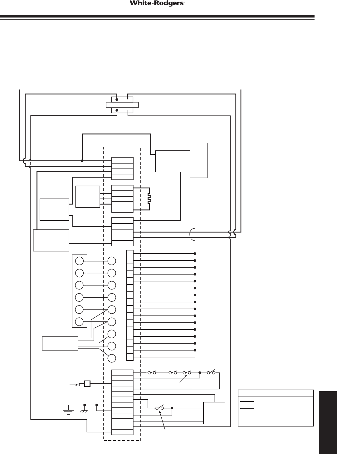
50V51-843 TYPICAL SYSTEM WIRING DIAGRAM
Low Voltage (24 VAC)
Line Voltage (120 VAC)
LEGEND
N.C. = Normally closed switch
N.O. = Normally closed switch
HOT
(LINE)
NEUTRAL
(LINE)
120 VAC
24 VAC CLASS II
TRANSFORMER
50V51-843
24 VACTH TR
LINE
XFMR
EAC
HUM
CIRC N
HUM N
LINE N
XFMR N
EAC N
E2
INDUCER
HUMIDIFIER
(OPTIONAL)
ELECTRONIC
AIR CLEANER
(OPTIONAL)
CONDENSING
UNITS
IGNITOR
IGN
IND HI
IND LO
IND N
IGN N
FLAME
SENSOR
PROBE
2ND STAGE PRESSURE
SWITCH (N. O.)
HIGH LIMIT
(N. C.)
AUX. HIGH
LIMIT (N. C.)
1ST STAGE PRESSURE
SWITCH (N. O.)
GAS
VALVE
HLO
HLI
FP
PS1
MVL
MVH
GND
GND
PS2
MV COM
TR
TH
ROLLOUT
SWITCH (N. C.)
CIRCULATOR
CIRC.
INTER-
FACE
www.white-rodgers.com 181
TECHNICAL HELP
DIAGNOSTIC FEATURES
The control continuously monitors its own operation and the
operation of the system. If a failure occurs the diagnostic in-
dicatorLED(DSI)willasha“RED”failurecode.If a failure
is internal to the control the “RED” indicator will stay on
continuously. In this case, the entire control should be
replaced as the control is not eld-repairable. If the LED is
continuously OFF, there may be no power to the control or a
failure within the control. If the sensed failure is in the system
(externaltothecontrol),theLEDwillashREDinthesequence
listedintheDiagnosticTable.TheLEDwillalsoindicate“System
Status”aspertheAmberandGreenLEDsignatureslistedinthe
DiagnosticTable.TheLEDwillashoneREDashatpowerup.
CFM INDICATOR
TheLED(DS2)CFMasheswhentheblowermotorisrunning.
TheashingindicatesthemotorCFM(cubicfeetperminute)
INTEGRATED
FURNACE CONTROLS
21V51U-843
OPERATION
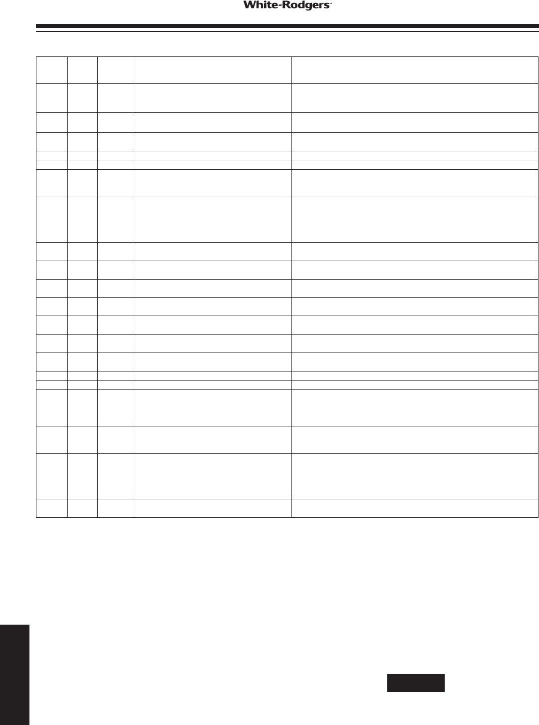
TRI-COLOR (DSI LED) DIAGNOSTIC TABLE
Green
LED
Flash
Amber
LED
Flash
Red LED
Flash
Error/Condition Comments/Troubleshooting
1Flamesensedwhennoameshouldbepresent Verify the gas valve is operating and shutting down properly. Flame in burner
assembleshouldextinguishpromptlyattheendofthecycle.Checkorices
and gas pressure.
2Pressureswitchstuckclosed/inducererror Pressureswitchstuckclosed.Checkswitchfunction,verifyinduceristurning
off.
31st-stagepressureswitchstuckopen/inducer
error
Checkpressureswitchfunctionandtubing.Verifyinduceristurningonthe
pullingsufcientvacuumtoengageswitch.
4 Open limit switch Verify continuity through rollout switch circuit.
5 Open rollout/open fuse detect Verifycontinuitythroughrolloutswitchcircuit,checkfuse.
61st-stagepressureswitchcyclelockout Iftherststagepressureswitchcycles5times(open,closed)duringonecall
forheatfromthethermostatthecontrolwilllockout.Checkpressureswitch
foruttering,inconsistentclosureorpoorvacuumpressure.
7Externallockout(retriesexceeded) Failuretosenseameisoftencausedbycarbondepositsontheame
sensor,adisconnectedorshortedamesensorleadorapoorlygrounded
furnace. Carbon deposits can be cleaned with emery cloth. Verify sensor is
notcontactingtheburnerandislocatedinagoodpositiontosenseame.
Checksensorleadforshortingandverifyfurnaceisgroundedproperly.
8Externallockout(ignitionrecyclesexceeded
whereameisestablishedandthenlost)
Checkitemsforexceededretrieslistedaboveandverifyvalveisnot
droppingoutallowingametobeestablishedandthenlost.
9 Grounding or Reversed polarity Verifythecontrolandfurnaceareproperlygrounded.Checkandreverse
polarity (primary) if incorrect.
10 Module gas valve contacts energized with no
call for heat
Verify valve is not receiving voltage from a short. If a valve wiring is correct
and condition persists, replace module.
11 Limit switch open – possible blower failure
overheating limit
Possibleblowerfailure,restrictedairowthroughapplianceorductwork.
Verify continuity through limit switch circuit and correct overheating cause.
12 Module Ignitor contact failure Fault code indicates the module ignitor contacts are not functioning properly.
Replace module.
Solid Module - internal fault condition Module contacts for gas valve not operating or processor fault. Reset control.
if condition persists replace module.
3
double
2nd-stagePressureSwitchStuckOpen/Inducer
Error
Checkpressureswitchfunctionandtubing.Verifyinduceristurningonand
pullingsufcientvacuumtoengageswitch.
1NormalOperationwithcallforrststageheat Normaloperation-rststage
2 Normal Operation with call for second stage heat Normaloperation-rststage
3 W2 present with no W1 Secondstagecallforheatonthermostatcircuitwithnocallforrststage.
VerifyDIPswitchesaresetfortwostagethermostatandcheckthermostat
rststagecircuit.Conguredforamulti-stagethermostattheModulewillnot
initiateheatingunlessrststagecallfromthermostatisreceived.
4YpresentwithnoGcall Modulewillallowcoolingtooperatewithonlya"Ysignalfromthethermostat
butwillalsotriggerthiscode.Verifythermostatisenergizingboth"Y"and"G"
oncallforcool.Check"G"terminalconnections.
Rapid Lowamesensecurrent Lowamesensecurrentisoftencausedbycarbondepositsontheame
sensor,apoorlygroundedfurnaceoramis-alignedamesenseprobe.
Carbondepositscanbecleanedwithemerycloth.Checkforimprove
furnaceandmoduleground.Verifysensorislocatedinorverynearameas
speciedbytheappliancemanufacturer.
1 Standby or Call for Cool Normal operation. Waiting for call from thermostat or receiving thermostat
call for cool.
airowdesignatedbythefurnacemanufacturer.Consultthe
furnacemanufacturerforashcodedetail.
FAULT CODE RETRIEVAL
Toretrievefaultcodes,pushandreleasethe“LASTERROR”
button for more than 1/5 second and less than 5 seconds.
(Control will indicate this period by solid GREEN for 1/5 secs.
to5secs.).TheLEDwill ashup tove storedfault codes,
beginning with the most recent. If there are no fault codes in
memory,theLEDwillashtwogreenashes.Thecontrolwill
ashthemostrecenterrorrstandtheoldesterrorlast(lastin
rstout).Thereshallbe2secondsbetweencodes.SolidLED
error codes will not be displayed.
NOTE
These error codes may be different from furnace label or
furnace manual.
www.white-rodgers.com
182
TECHNICAL HELP
