Wi Lan AP01 User Manual 300 24changepages

Wi Lan Inc 300 24changepages

Contents

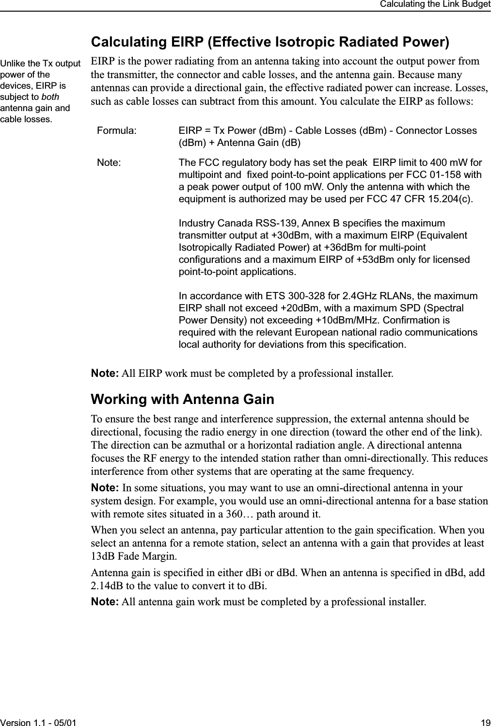
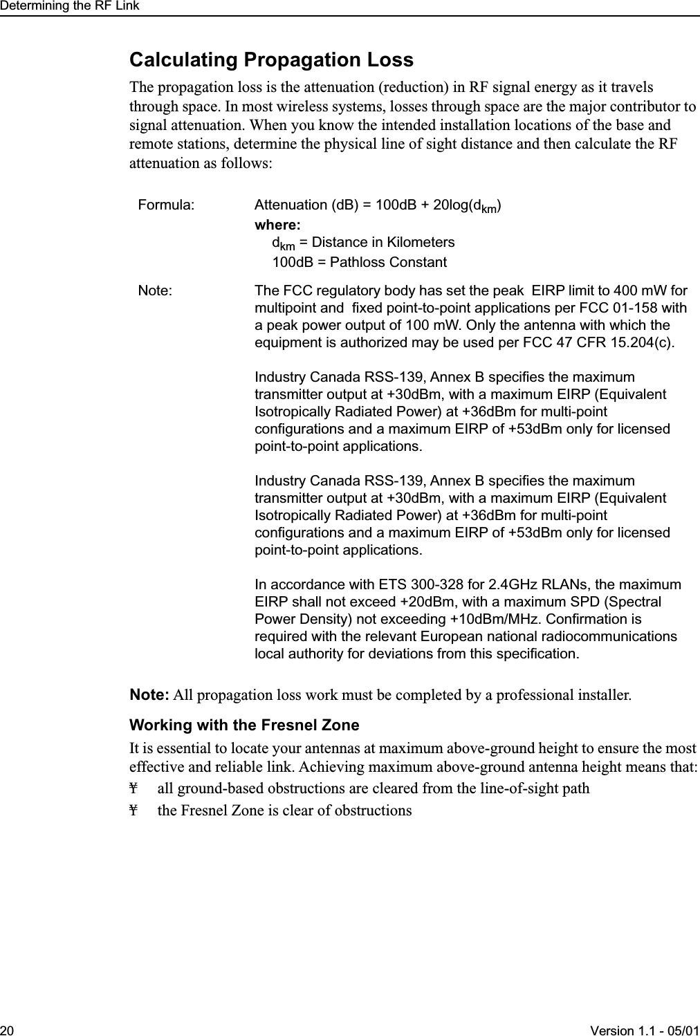
300 24 Manual Replace Sheet

 MAY 2001 1 May 2001 Change to I.WiLL 300-24 Access Point Manual Please replace pages 19—20 of the I.WiLL 300-24 Access Point manual (Version 1.1 - 02/00) with the attached replacement page. Information about EIRP has been clarified and corrected on the replacement page.
 Calculating the Link BudgetVersion 1.1 - 05/01 19 Calculating EIRP (Effective Isotropic Radiated Power) EIRP is the power radiating from an antenna taking into account the output power from the transmitter, the connector and cable losses, and the antenna gain. Because many antennas can provide a directional gain, the effective radiated power can increase. Losses, such as cable losses can subtract from this amount. You calculate the EIRP as follows: Note:  All EIRP work must be completed by a professional installer. Working with Antenna Gain To ensure the best range and interference suppression, the external antenna should be directional, focusing the radio energy in one direction (toward the other end of the link). The direction can be azmuthal or a horizontal radiation angle. A directional antenna focuses the RF energy to the intended station rather than omni-directionally. This reduces interference from other systems that are operating at the same frequency. Note:  In some situations, you may want to use an omni-directional antenna in your system design. For example, you would use an omni-directional antenna for a base station with remote sites situated in a 360… path around it.When you select an antenna, pay particular attention to the gain specification. When you select an antenna for a remote station, select an antenna with a gain that provides at least 13dB Fade Margin.Antenna gain is specified in either dBi or dBd. When an antenna is specified in dBd, add 2.14dB to the value to convert it to dBi. Note:  All antenna gain work must be completed by a professional installer. Formula: EIRP = Tx Power (dBm) - Cable Losses (dBm) - Connector Losses (dBm) + Antenna Gain (dB)Note: The FCC regulatory body has set the peak  EIRP limit to 400 mW for multipoint and  fixed point-to-point applications per FCC 01-158 with a peak power output of 100 mW. Only the antenna with which the equipment is authorized may be used per FCC 47 CFR 15.204(c).Industry Canada RSS-139, Annex B specifies the maximum transmitter output at +30dBm, with a maximum EIRP (Equivalent Isotropically Radiated Power) at +36dBm for multi-point configurations and a maximum EIRP of +53dBm only for licensed point-to-point applications.In accordance with ETS 300-328 for 2.4GHz RLANs, the maximum EIRP shall not exceed +20dBm, with a maximum SPD (Spectral Power Density) not exceeding +10dBm/MHz. Confirmation is required with the relevant European national radio communications local authority for deviations from this specification.Unlike the Tx output power of the devices, EIRP is subject to both antenna gain and cable losses.
 Determining the RF Link20 Version 1.1 - 05/01 Calculating Propagation Loss The propagation loss is the attenuation (reduction) in RF signal energy as it travels through space. In most wireless systems, losses through space are the major contributor to signal attenuation. When you know the intended installation locations of the base and remote stations, determine the physical line of sight distance and then calculate the RF attenuation as follows: Note:  All propagation loss work must be completed by a professional installer. Working with the Fresnel Zone It is essential to locate your antennas at maximum above-ground height to ensure the most effective and reliable link. Achieving maximum above-ground antenna height means that:¥ all ground-based obstructions are cleared from the line-of-sight path¥ the Fresnel Zone is clear of obstructions Formula: Attenuation (dB) = 100dB + 20log(d km ) where: d km  = Distance in Kilometers100dB = Pathloss ConstantNote: The FCC regulatory body has set the peak  EIRP limit to 400 mW for multipoint and  fixed point-to-point applications per FCC 01-158 with a peak power output of 100 mW. Only the antenna with which the equipment is authorized may be used per FCC 47 CFR 15.204(c).Industry Canada RSS-139, Annex B specifies the maximum transmitter output at +30dBm, with a maximum EIRP (Equivalent Isotropically Radiated Power) at +36dBm for multi-point configurations and a maximum EIRP of +53dBm only for licensed point-to-point applications.Industry Canada RSS-139, Annex B specifies the maximum transmitter output at +30dBm, with a maximum EIRP (Equivalent Isotropically Radiated Power) at +36dBm for multi-point configurations and a maximum EIRP of +53dBm only for licensed point-to-point applications.In accordance with ETS 300-328 for 2.4GHz RLANs, the maximum EIRP shall not exceed +20dBm, with a maximum SPD (Spectral Power Density) not exceeding +10dBm/MHz. Confirmation is required with the relevant European national radiocommunications local authority for deviations from this specification.

Navigation menu