Wi Lan AP01 User Manual 300 24
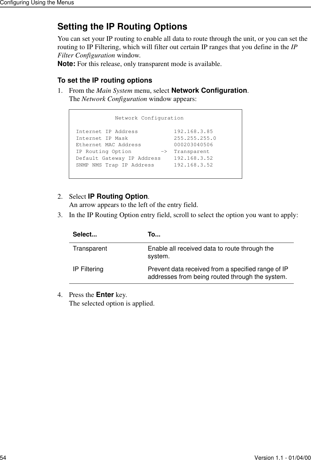
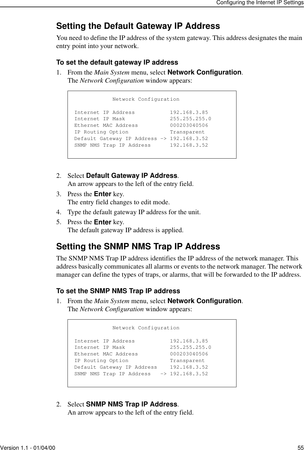
Wi Lan Inc 300 24
UserManual.wiki
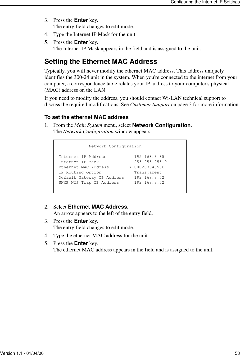
>
Wi Lan
>
AP01 User Manual
>
I Will 30024 Manual
Contents
1.
I Will 30024 Manual
2.
300 24 Manual Replace Sheet
I Will 30024 Manual
Navigation menu
Upload a User Manual
Namespaces
Wiki Guide
HTML
PDF
Info
Views
User Manual
Discussion / Help
Navigation
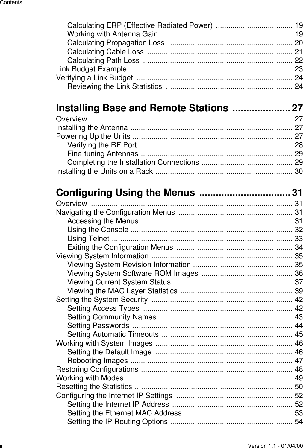
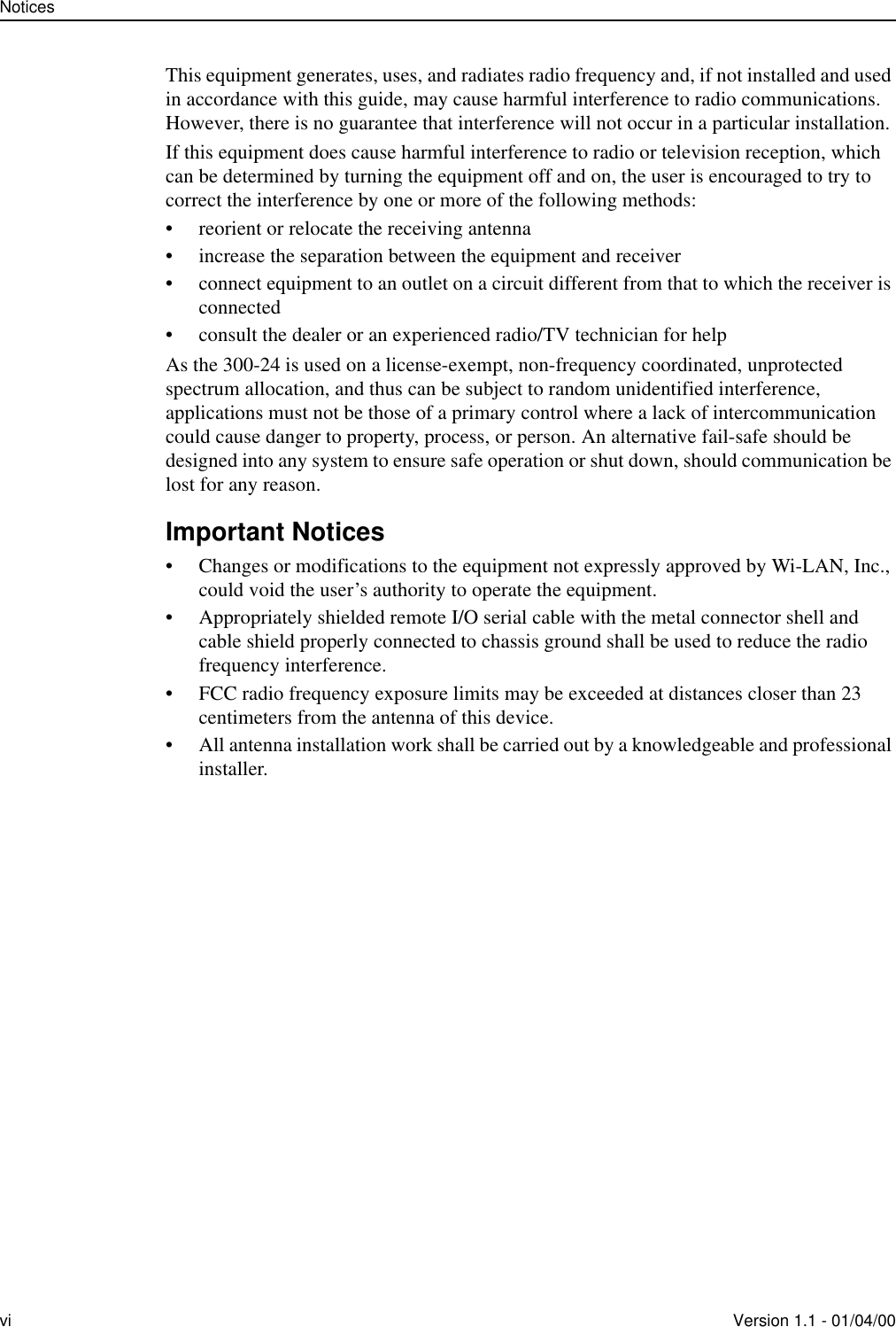
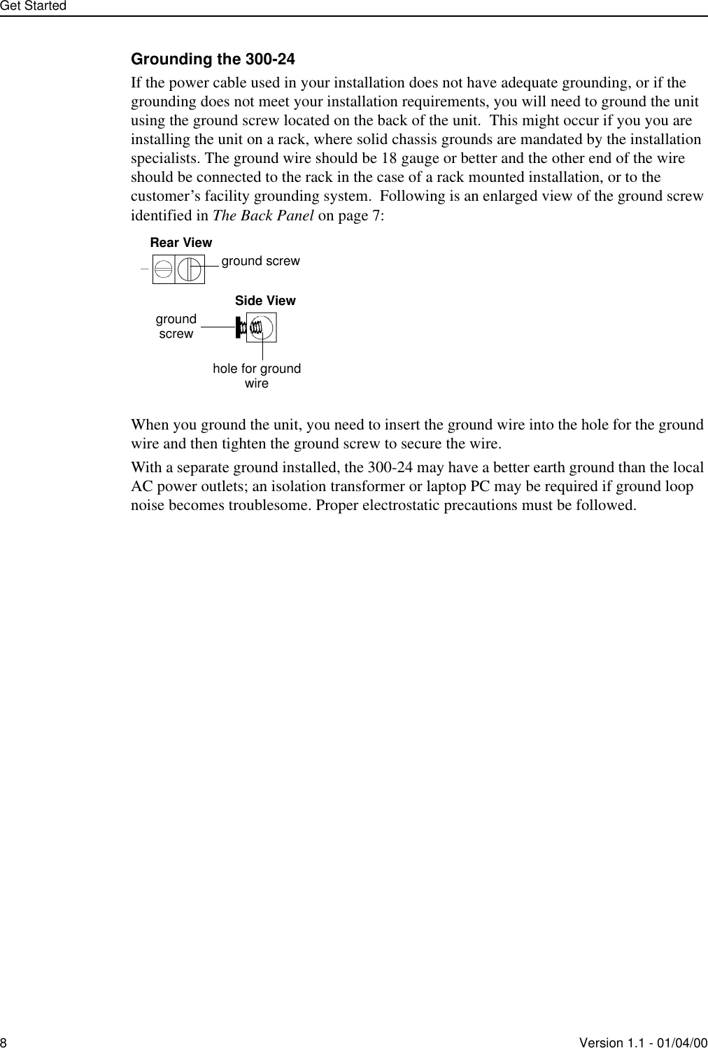
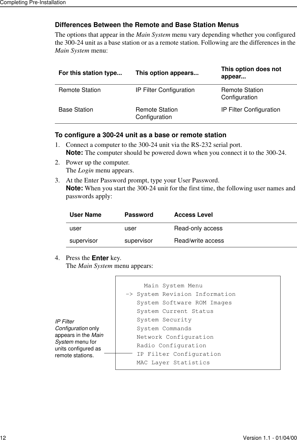
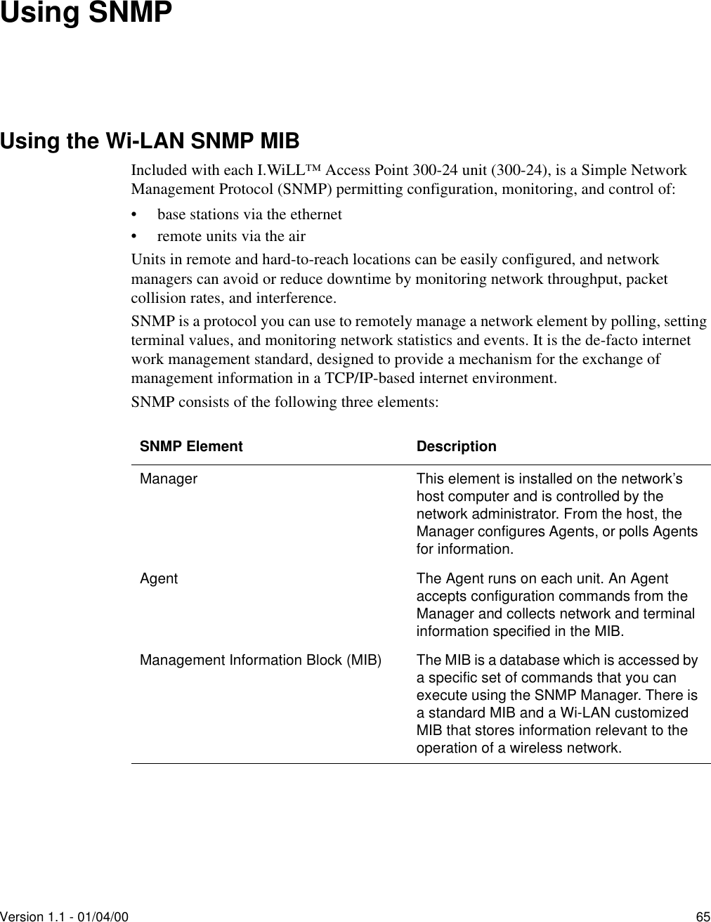
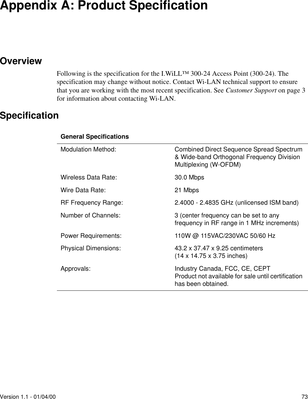
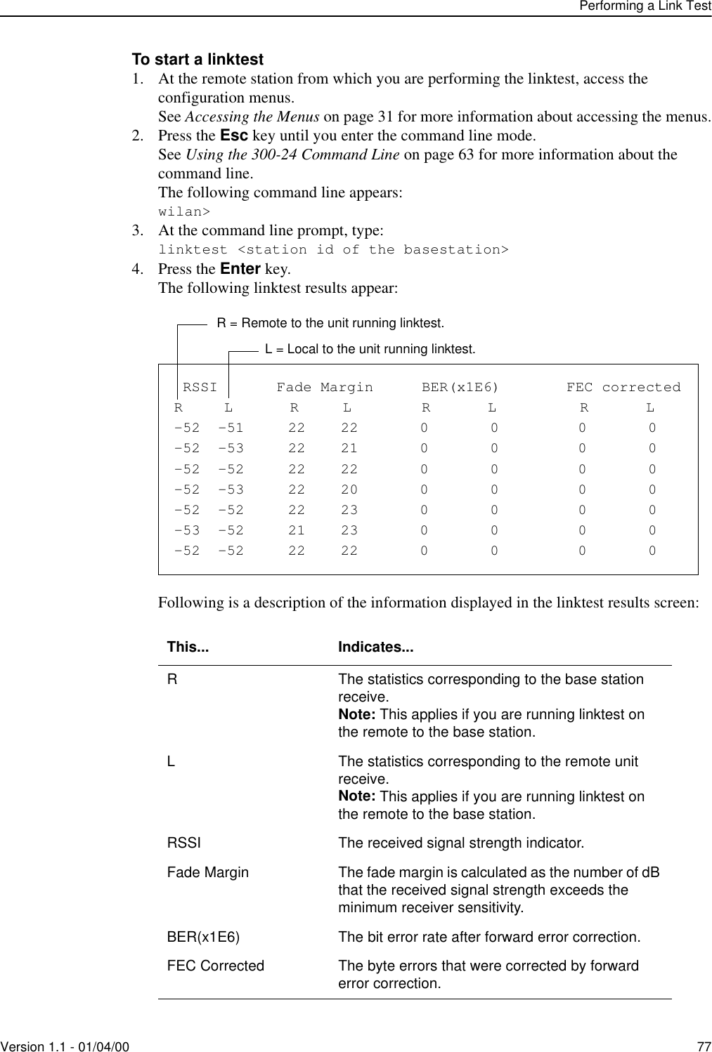
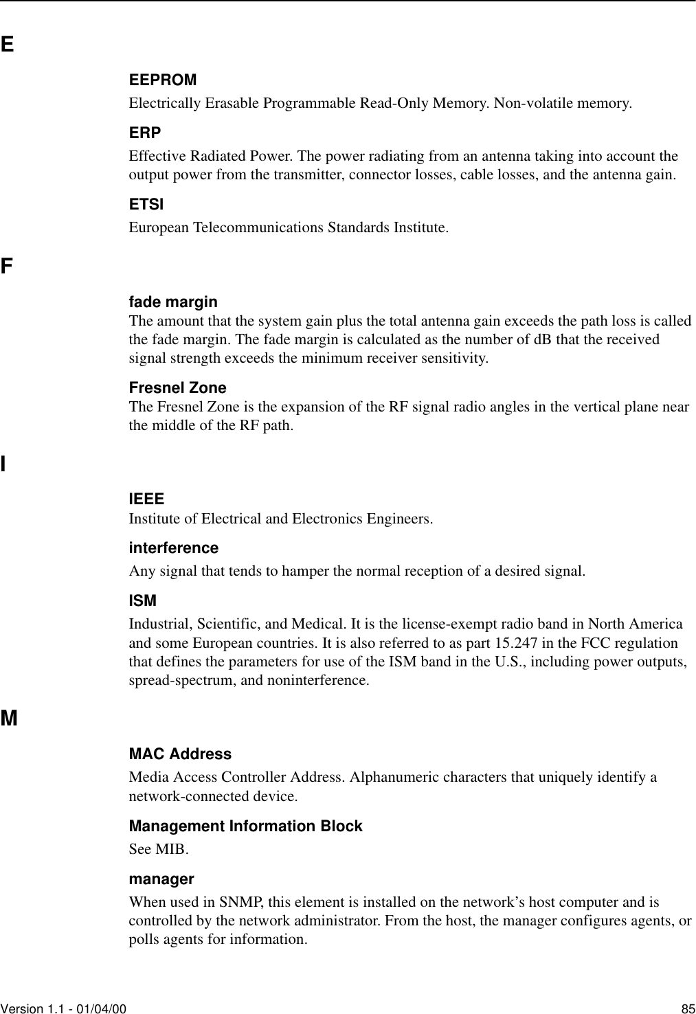
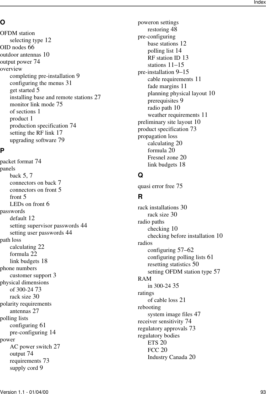
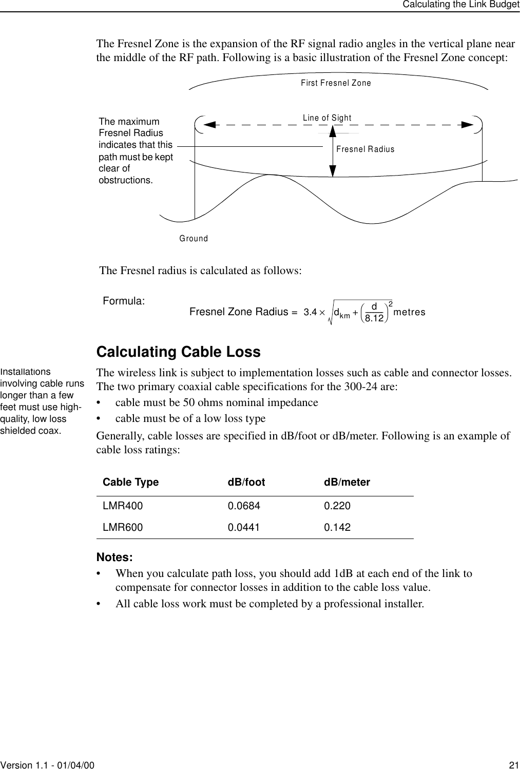
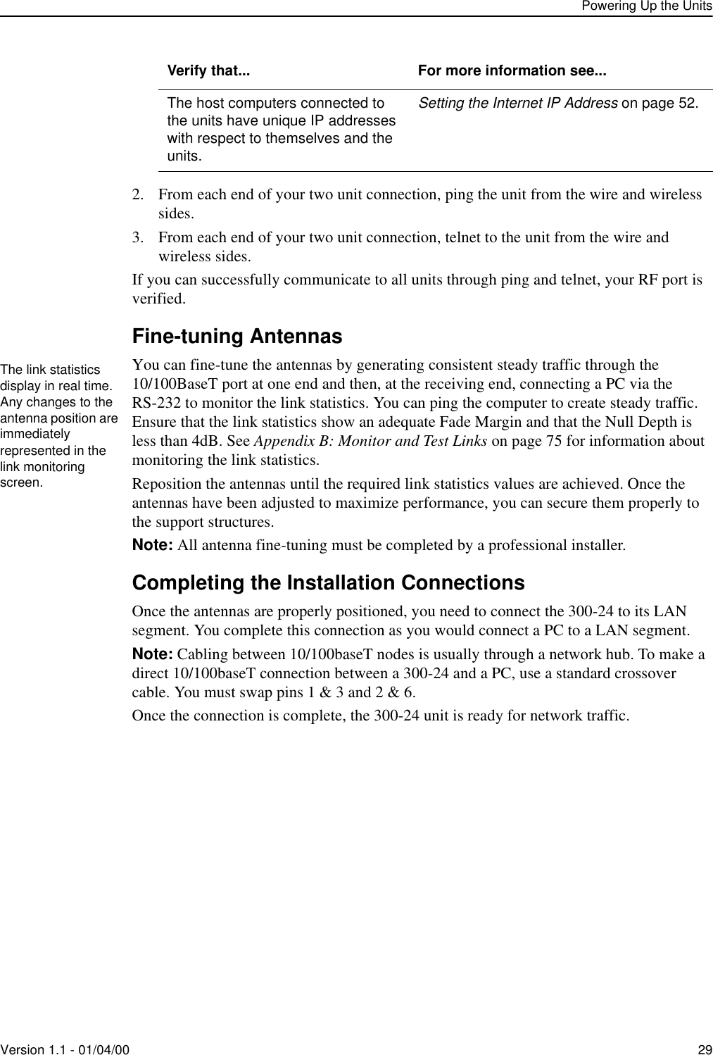
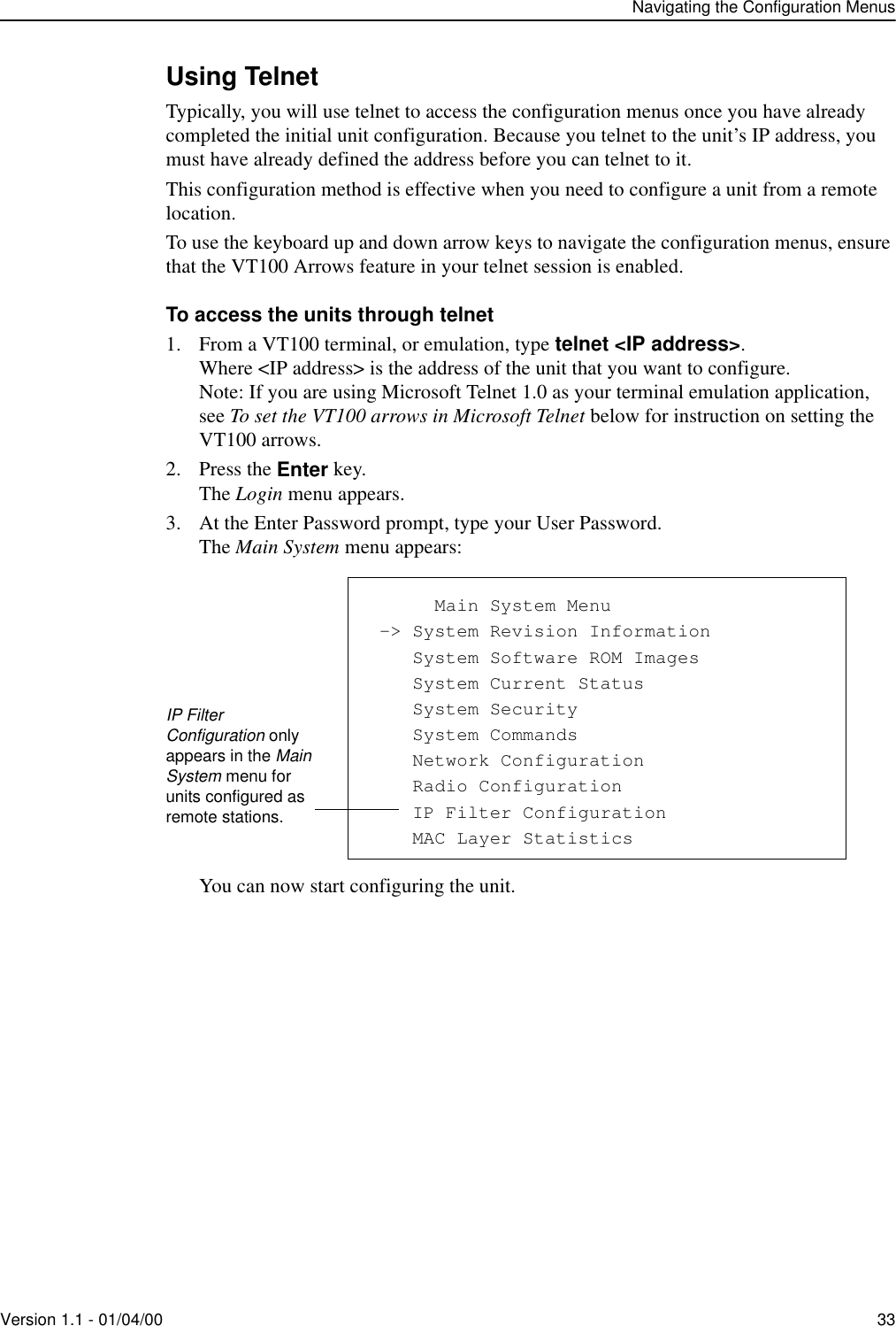
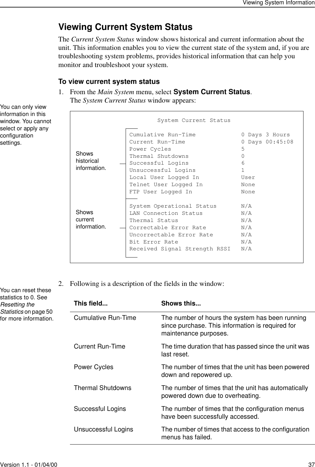
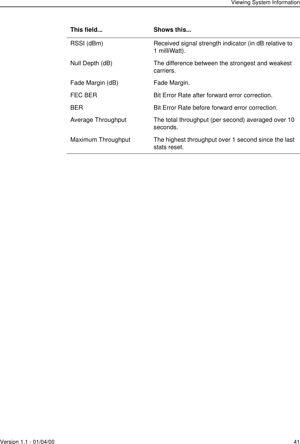
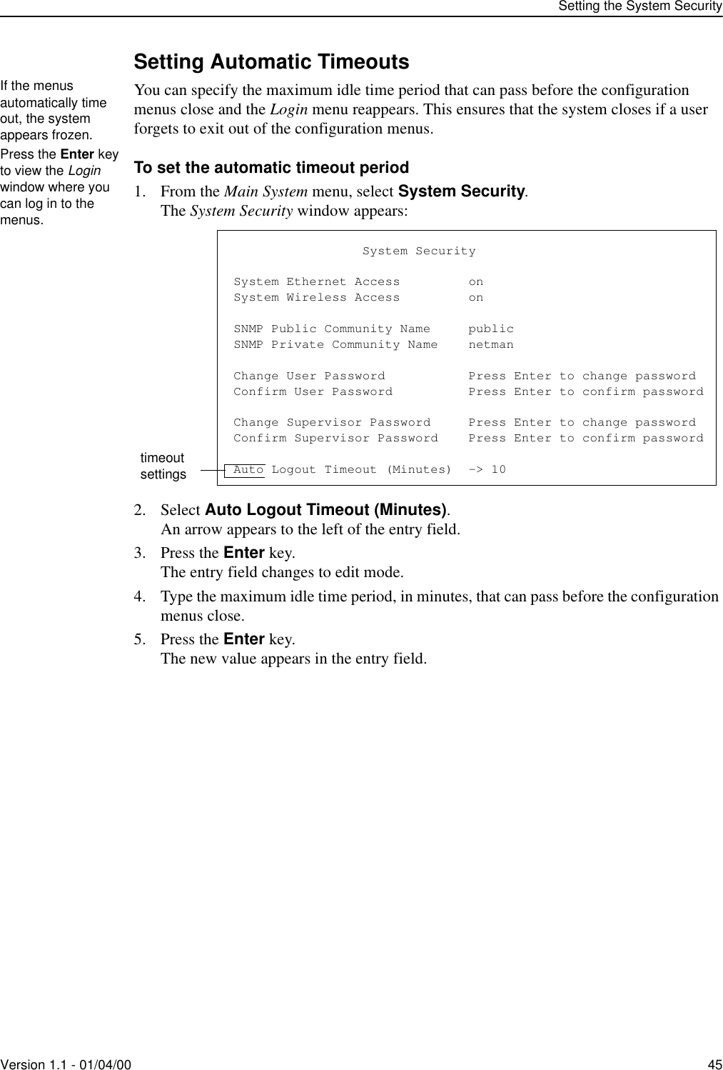
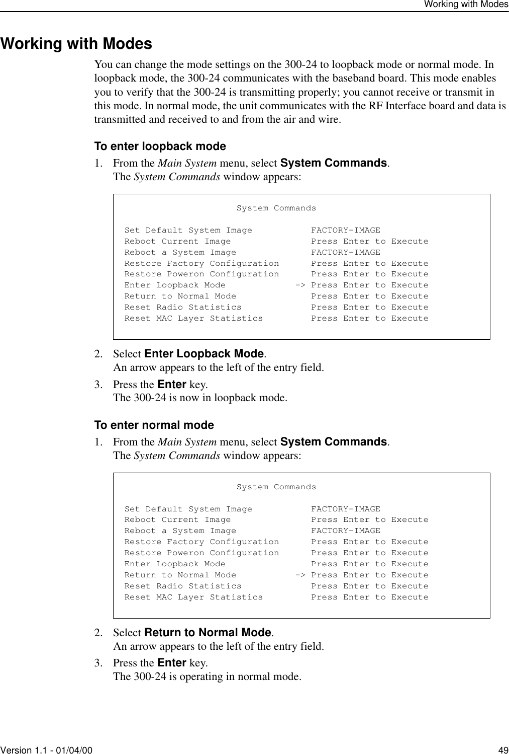
![Pre-configuring the StationsVersion 1.1 - 01/04/00 135. Select Radio Configuration.6. Press the Enter key.The Radio Configuration menu appears:7. Select OFDM Station Type.8. Press the Enter key.The OFDM Station Type entry field is highlighted.9. Complete the following steps depending on the type of station you are configuring:10. Press the Enter key.The unit is configured to the selected unit type.11. Leave the Radio Configuration menu open.To assign the base station or remote station an RF Station ID1. In the Radio Configuration menu, select RF Station ID [0..1023].2. Press the Enter key.The RF Station ID entry field is highlighted.3. Type a unique number for the RF Station ID.4. Press the Enter key.The unit is assigned the RF Station ID.5. Make a note of the RF Station ID you assigned to the unit.To configure a... Do this...Base Station In the OFDM Station Type entry field, scroll to select Base Unit.Remote Station In the OFDM Station Type entry field, scroll to select Remote Unit.Use the up and down arrow keys on the keyboard to select a menu item. Radio ConfigurationOFDM Station Type -> Remote UnitRF Station Id [0..1023] 2RF Network Id [0..1023] 0RF Center Frequency 2.440 GHz Radio ConfigurationOFDM Station Type Remote UnitRF Station Id [0..1023] -> 2RF Network Id [0..1023] 0RF Center Frequency 2.440 GHzEvery unit you configure must have a unique RF Station ID. No two units can have the same ID.](https://usermanual.wiki/Wi-Lan/AP01.I-Will-30024-Manual/User-Guide-91098-Page-19.png)
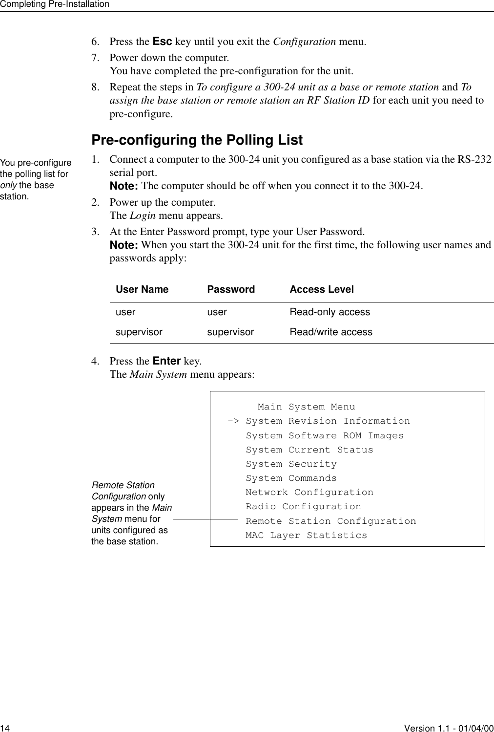
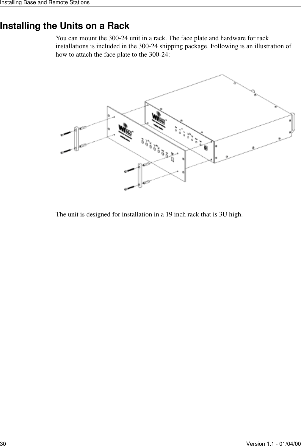
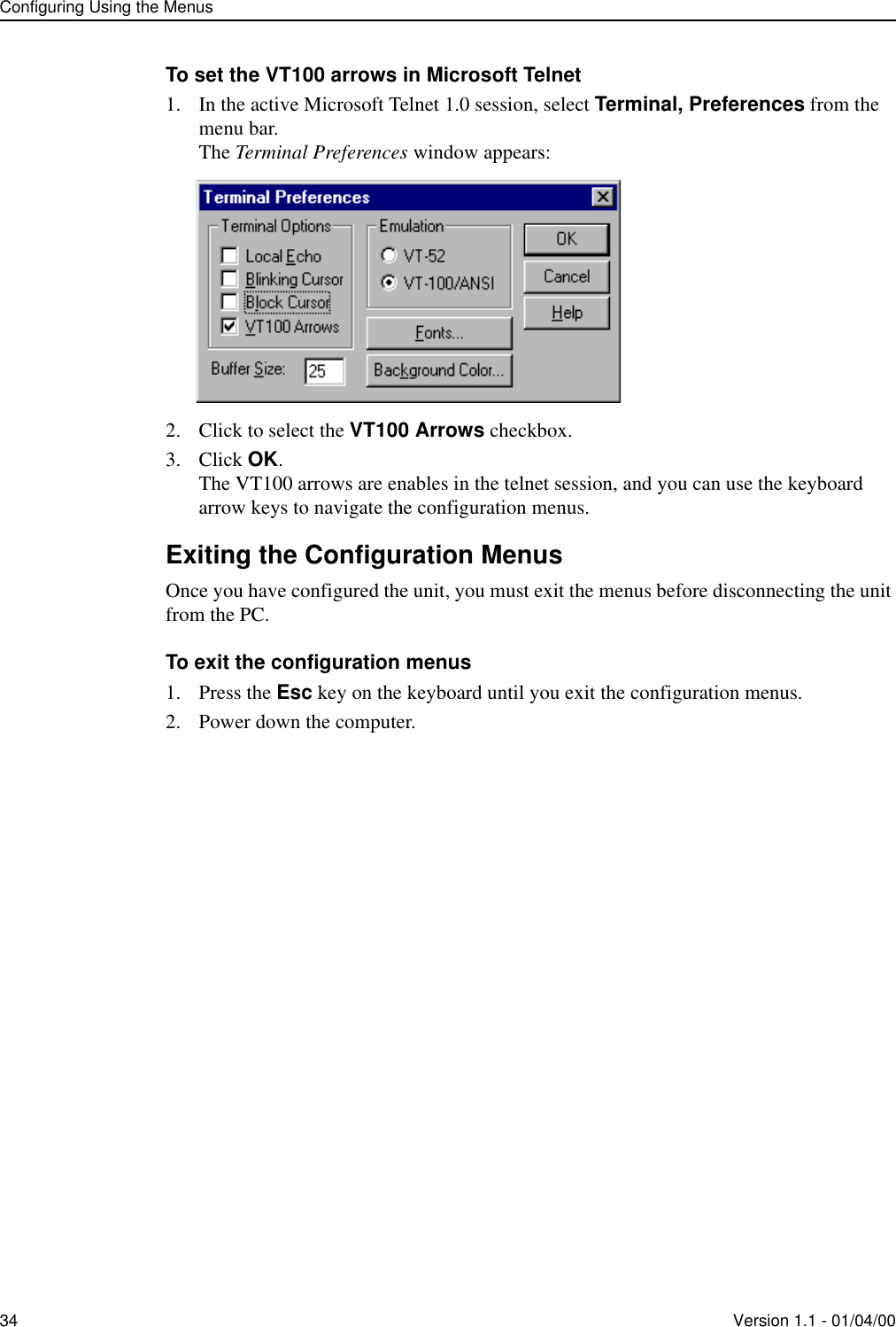
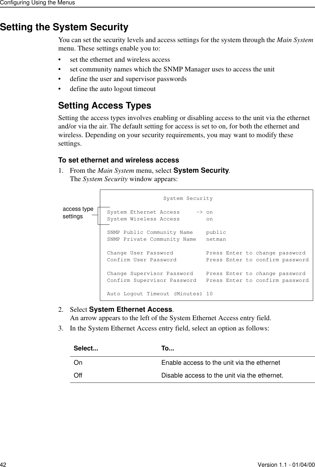
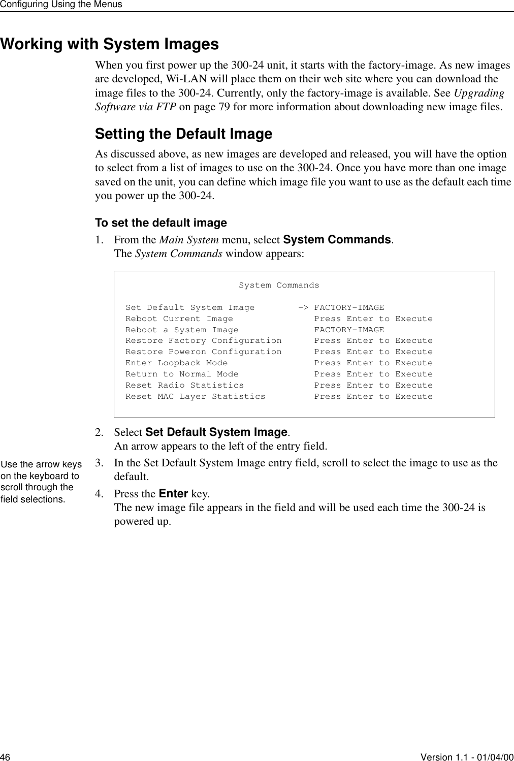
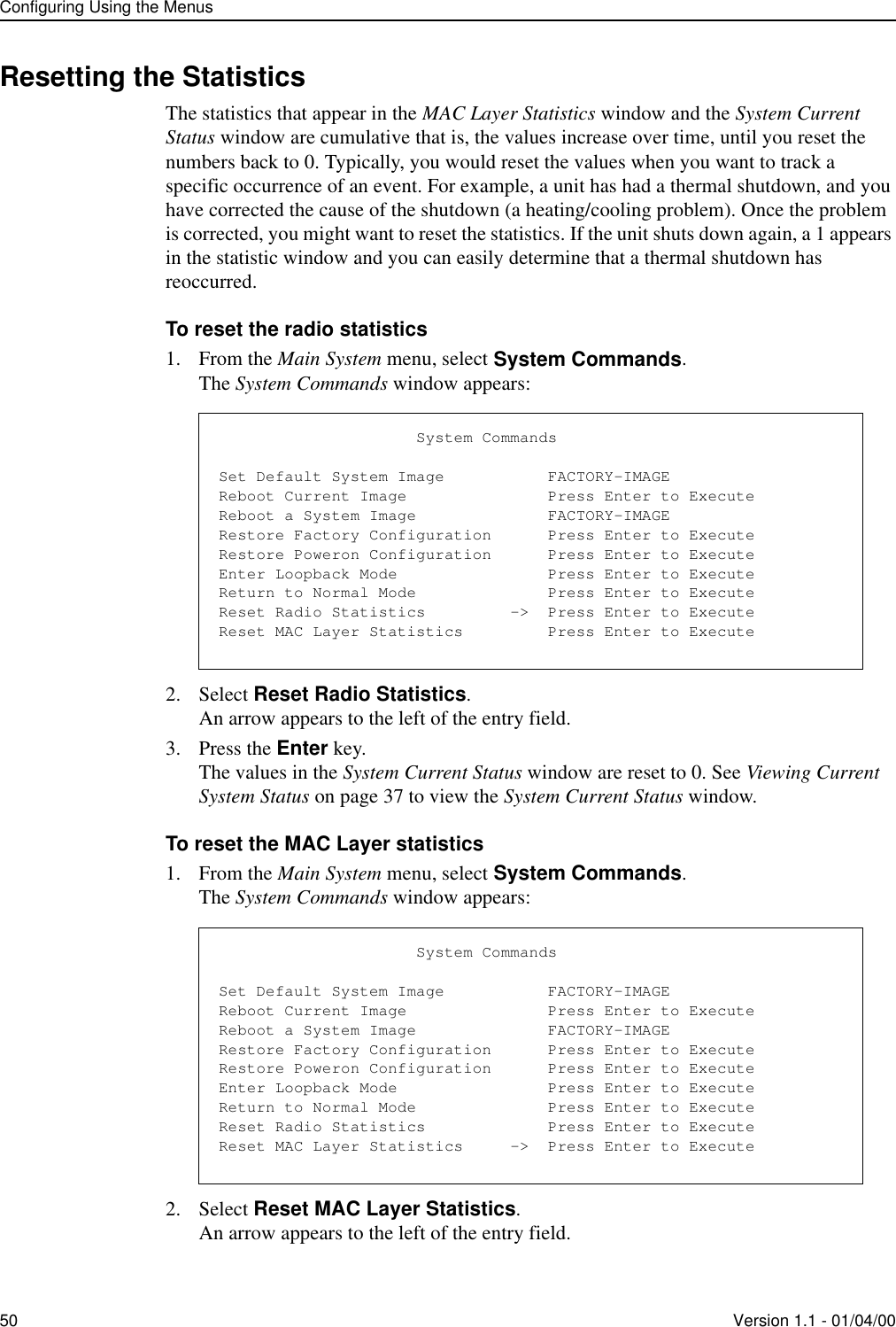
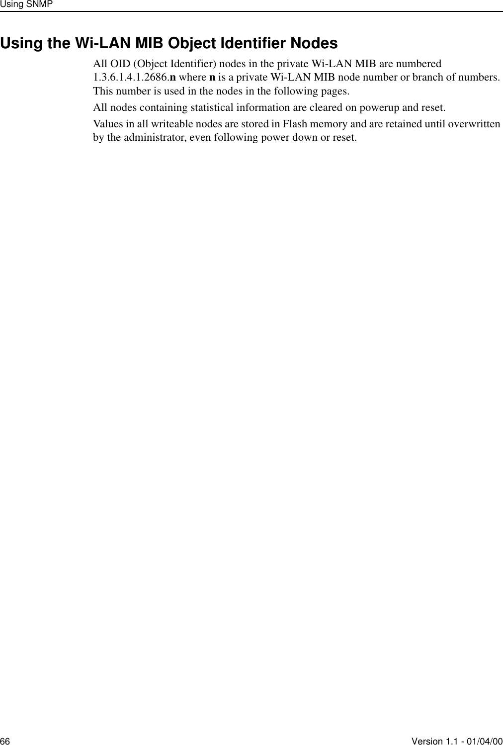
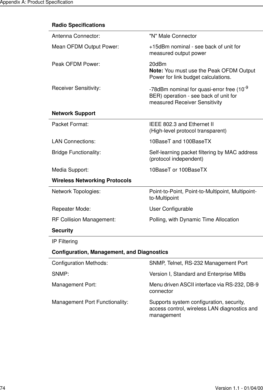
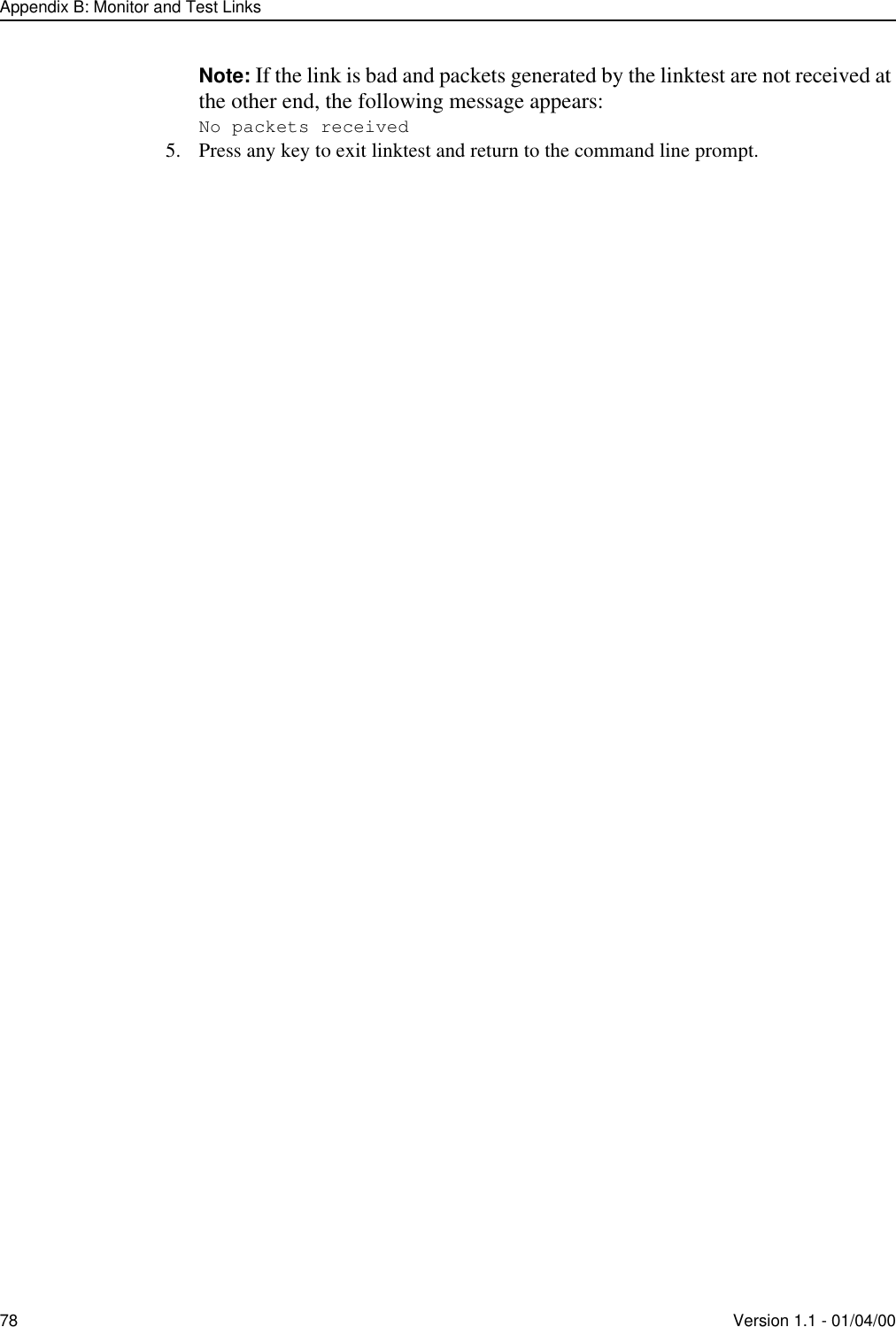
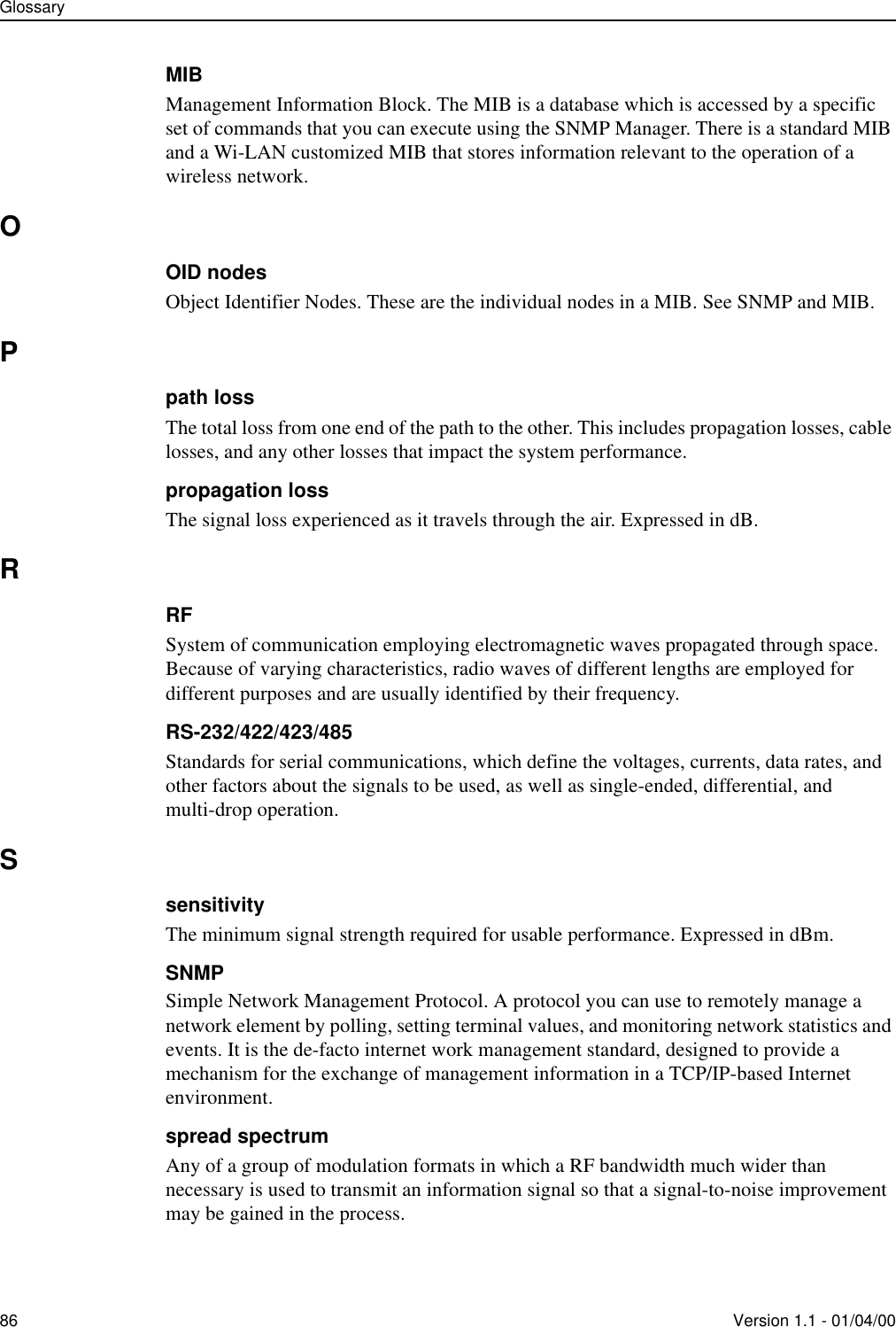
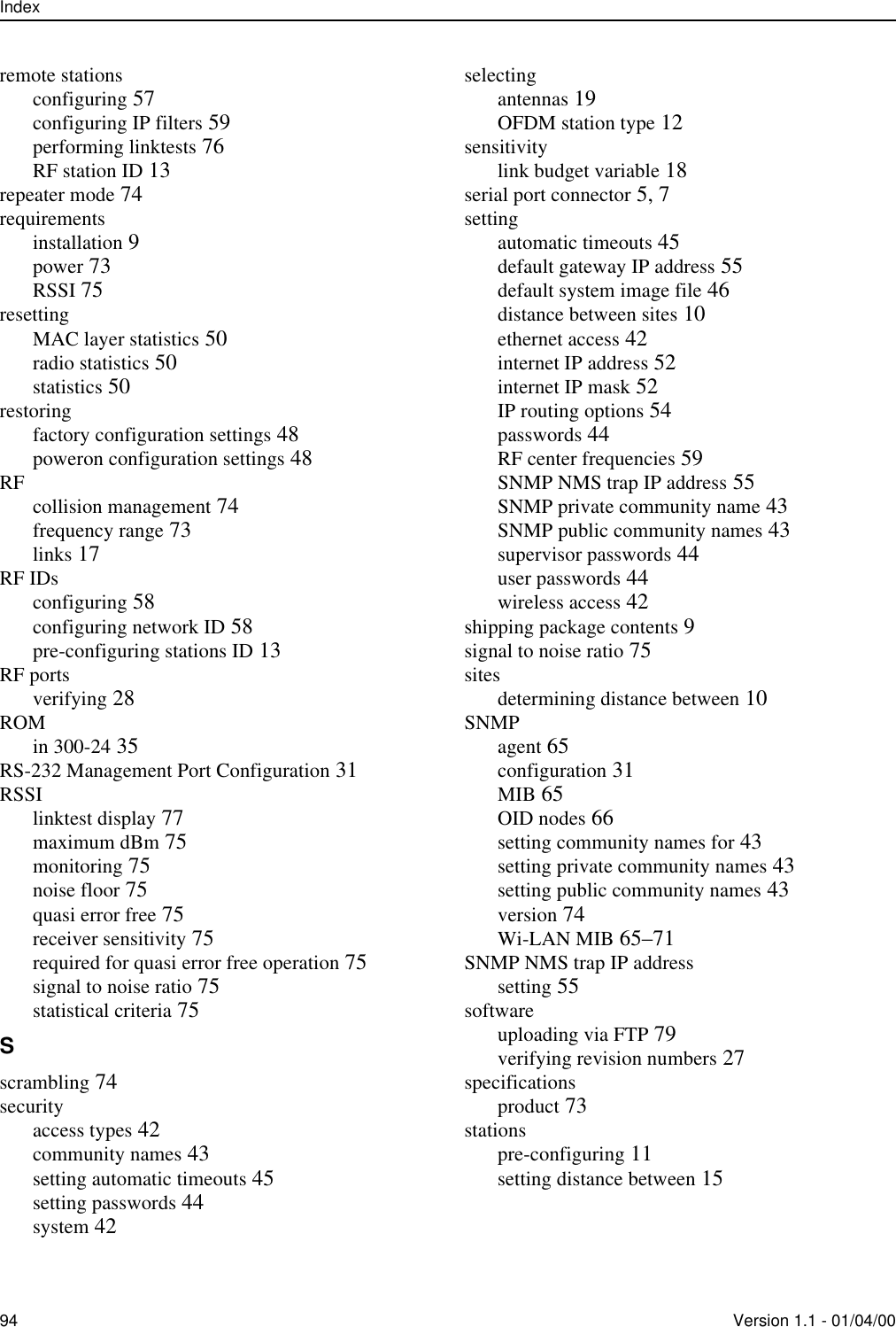
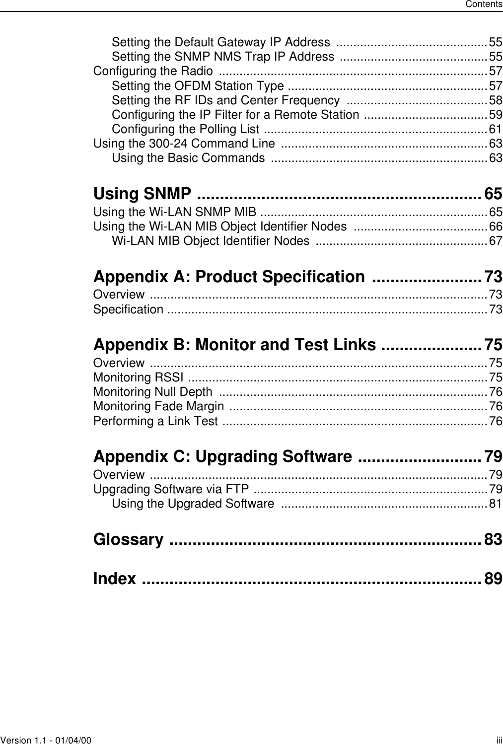
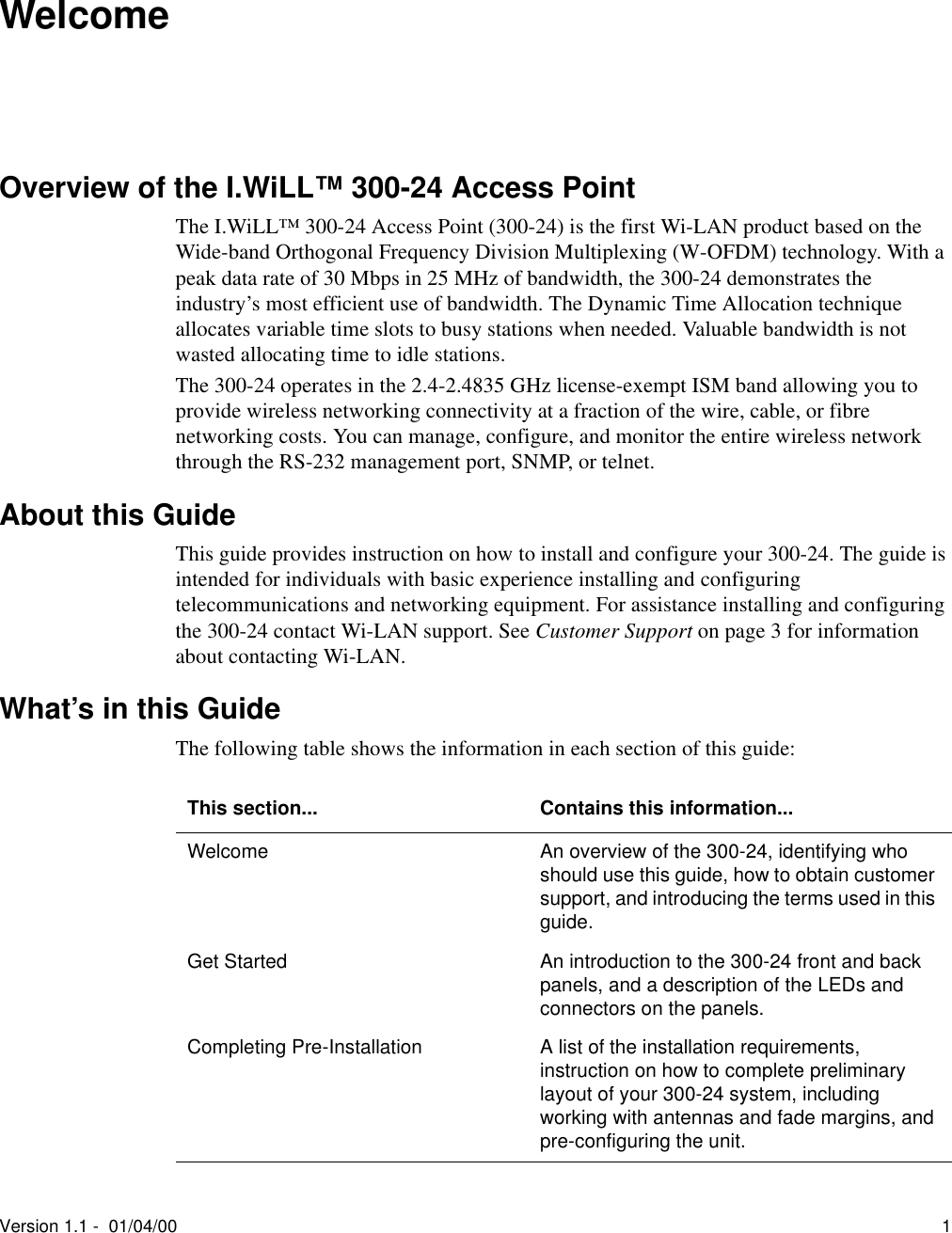
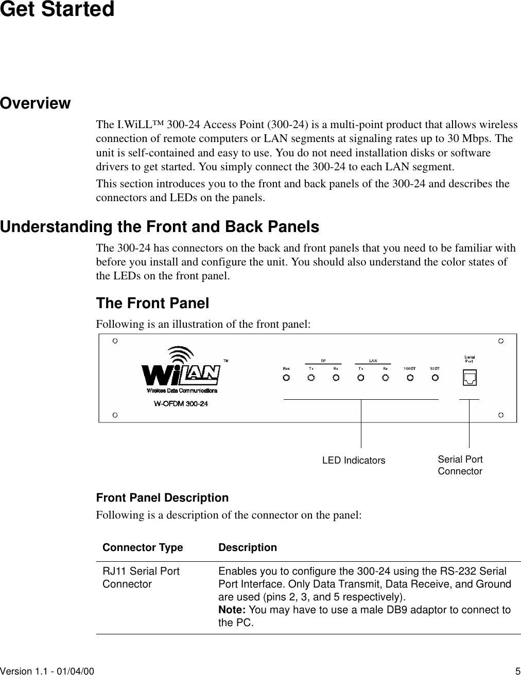
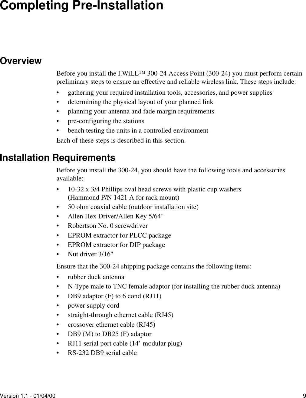
![Configuring the RadioVersion 1.1 - 01/04/00 57Configuring the RadioYou can configure the settings for the radio station type and the RF IDs and frequencies using the Radio Configuration window. These settings can be defined for both remote and base stations. You can also configure settings that are specific to remote stations or to base stations. These settings include:• IP Filtering, which applies to only remote stations• Polling Frequencies, which is configured and managed through the base stationSetting the OFDM Station TypeBefore you install and start using the 300-24 in a system, you need to define the unit as a base or a remote station. To set the OFDM station type1. From the Main System menu, select Radio Configuration.2. Press the Enter key.The Radio Configuration window appears:3. Select OFDM Station Type.An arrow appears to the left of the entry field.4. Press the Enter key.5. In the OFDM Station Type entry field, select a station type as follows:6. Press the Enter key.The unit is configured to the selected unit type.To configure a... Do this...Base Station In the OFDM Station Type entry field, scroll to select Base Unit.Remote Station In the OFDM Station Type entry field, scroll to select Remote Unit. Radio ConfigurationOFDM Station Type -> Remote UnitRF Station Id [0..1023] 2RF Network Id [0..1023] 0RF Center Frequency 2.440 GHz](https://usermanual.wiki/Wi-Lan/AP01.I-Will-30024-Manual/User-Guide-91098-Page-63.png)
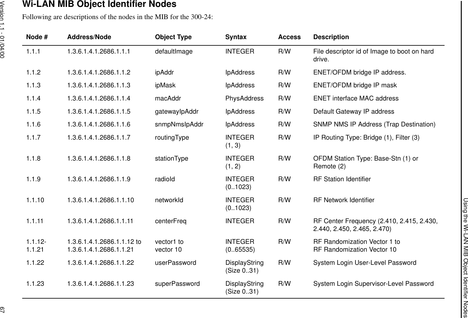
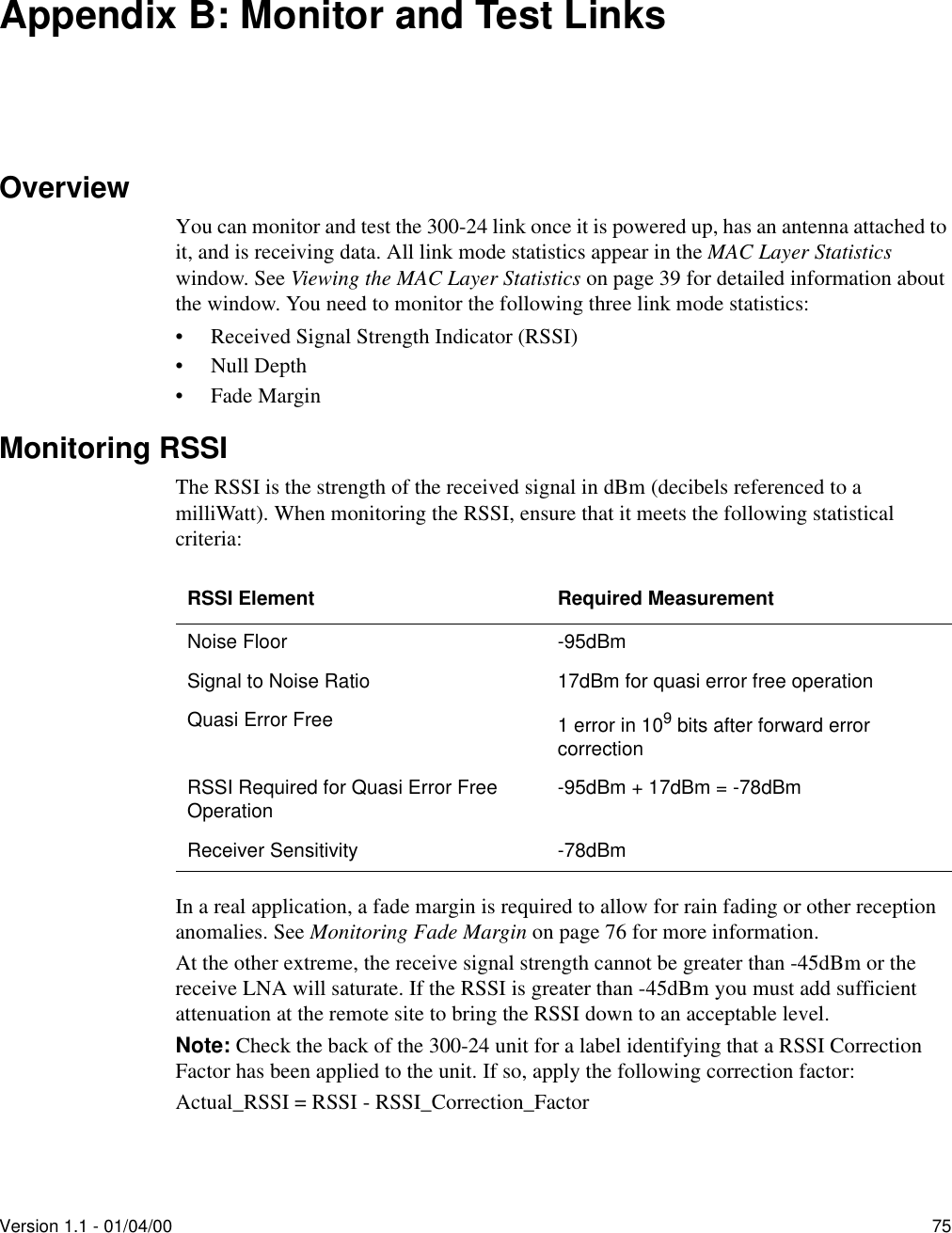
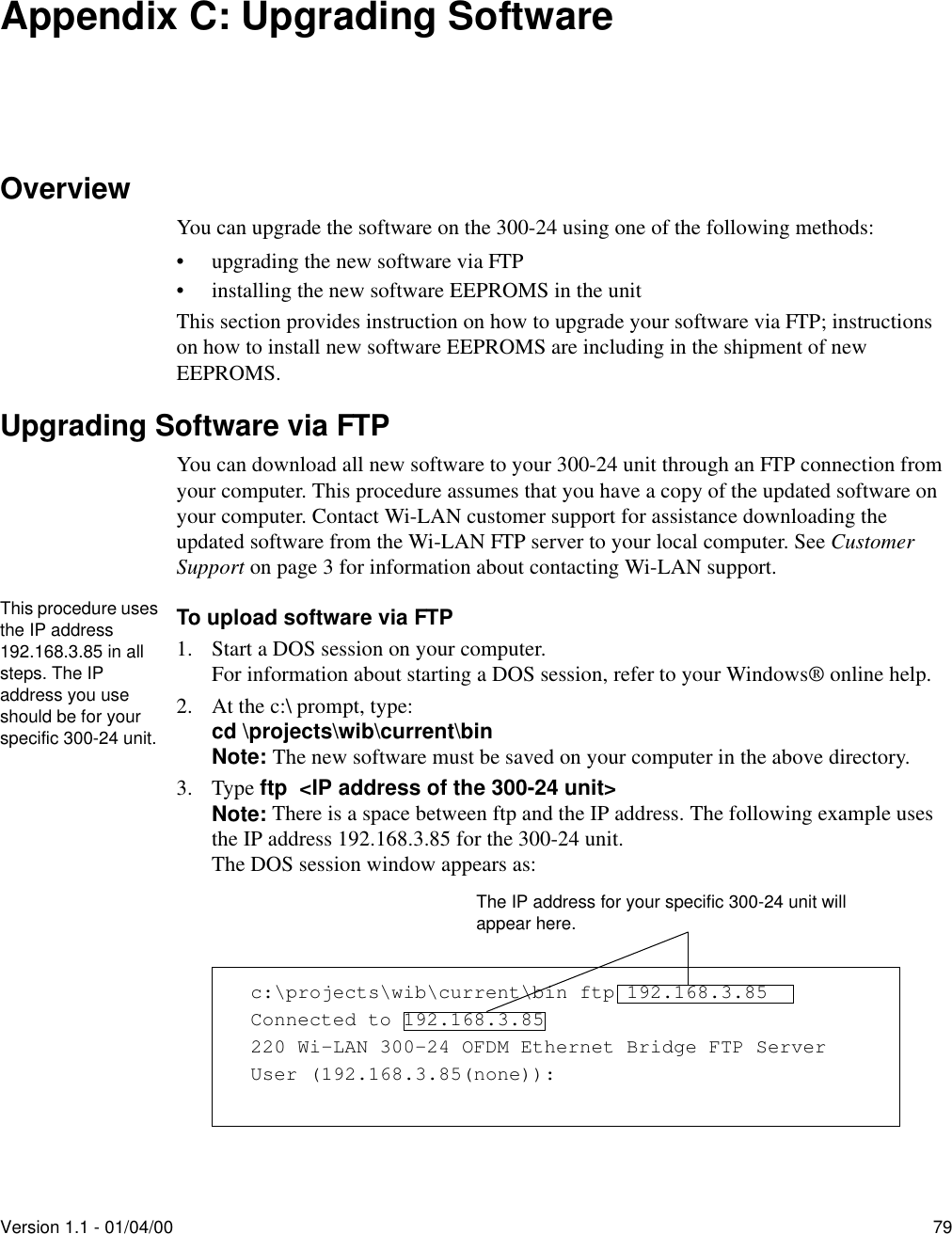
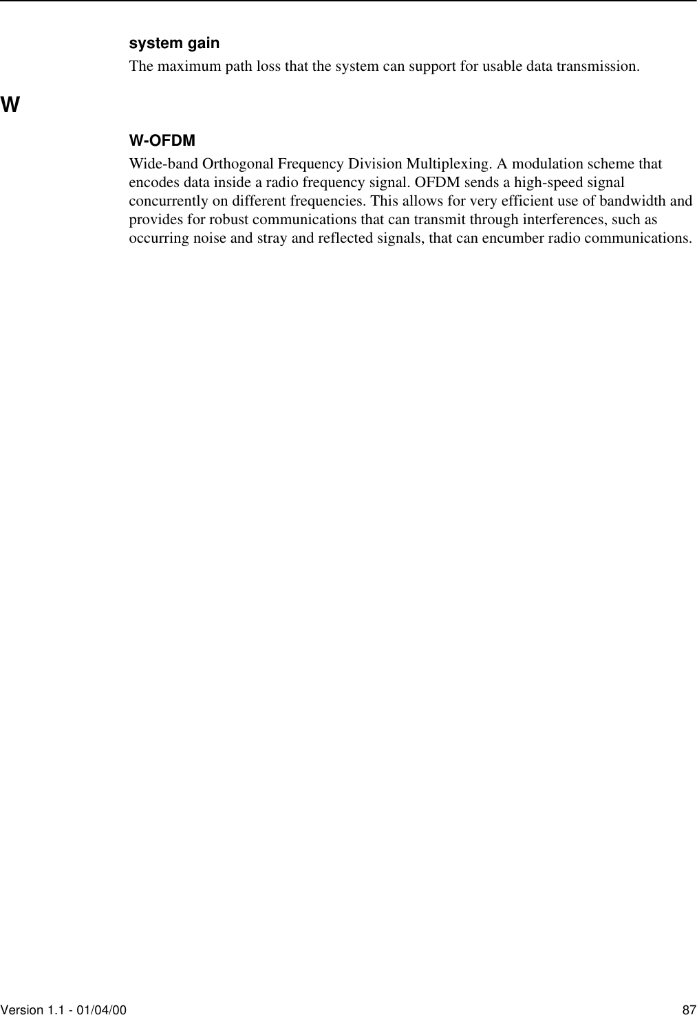
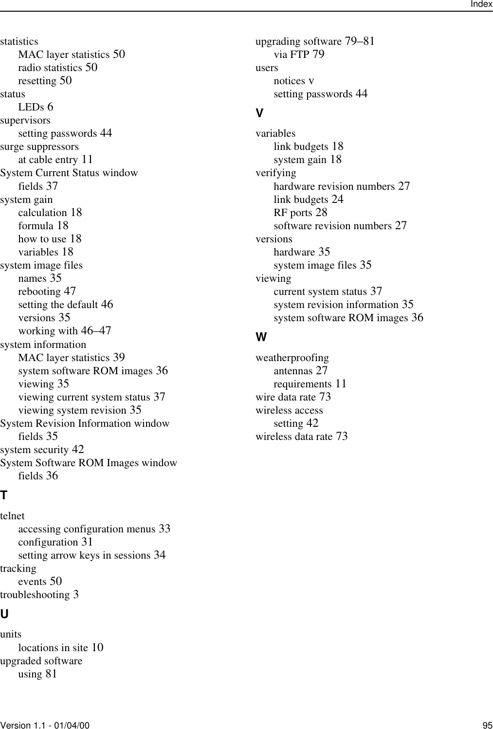
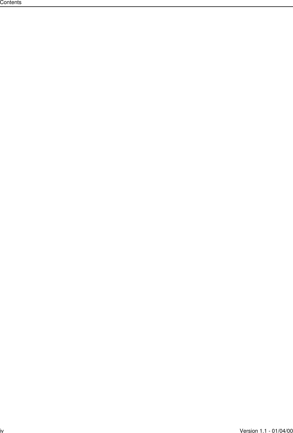
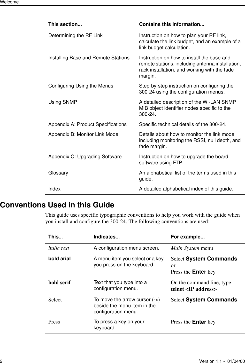
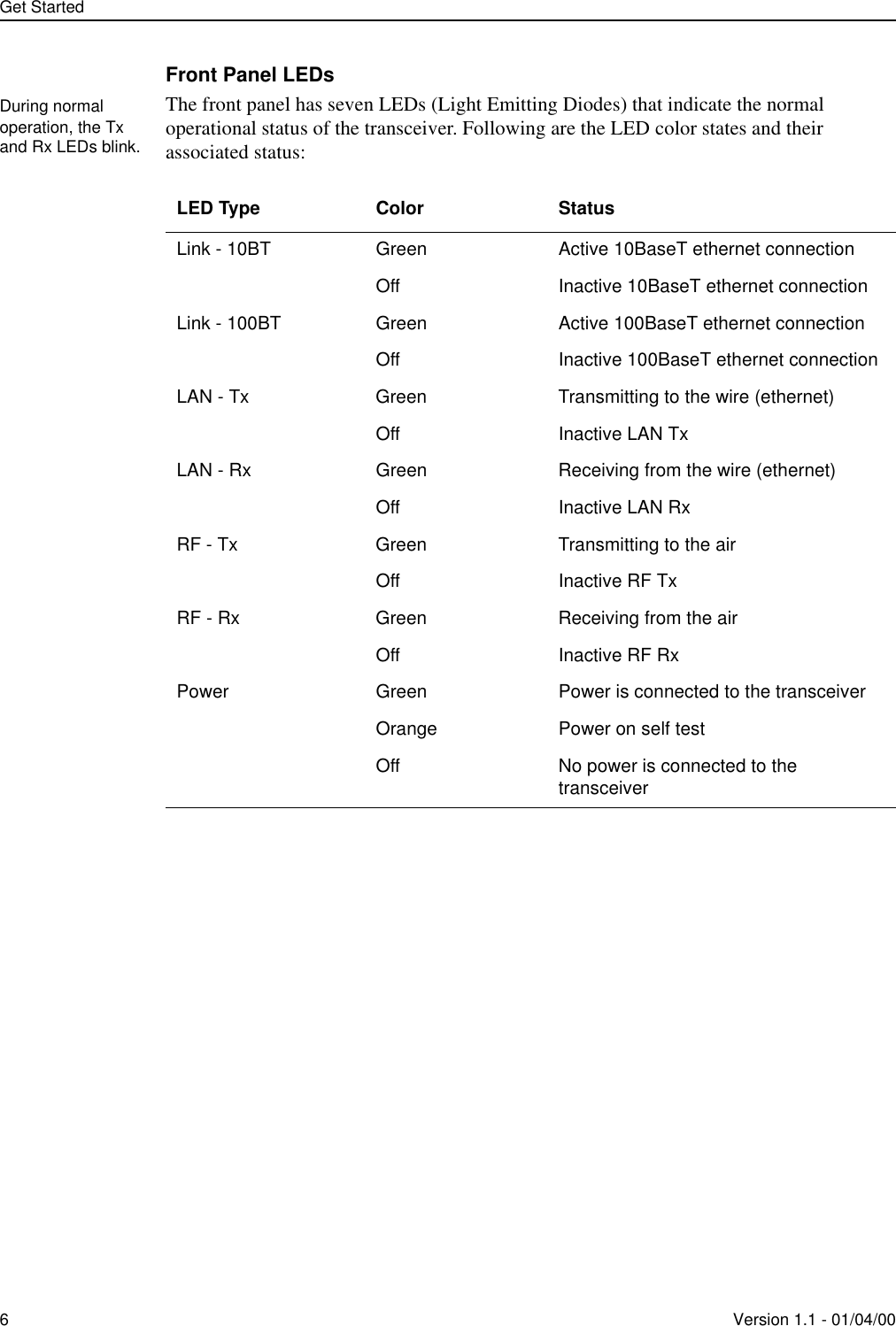
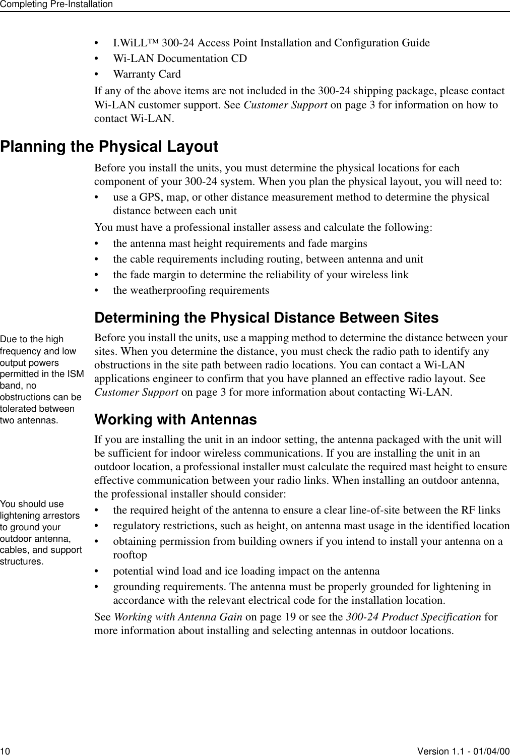
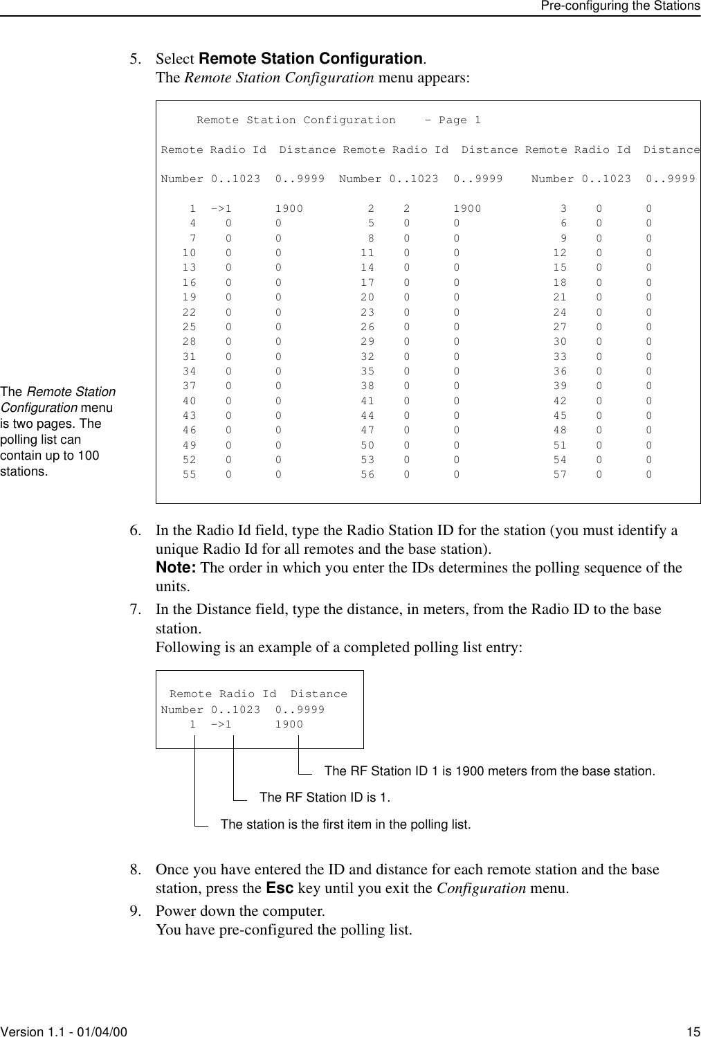
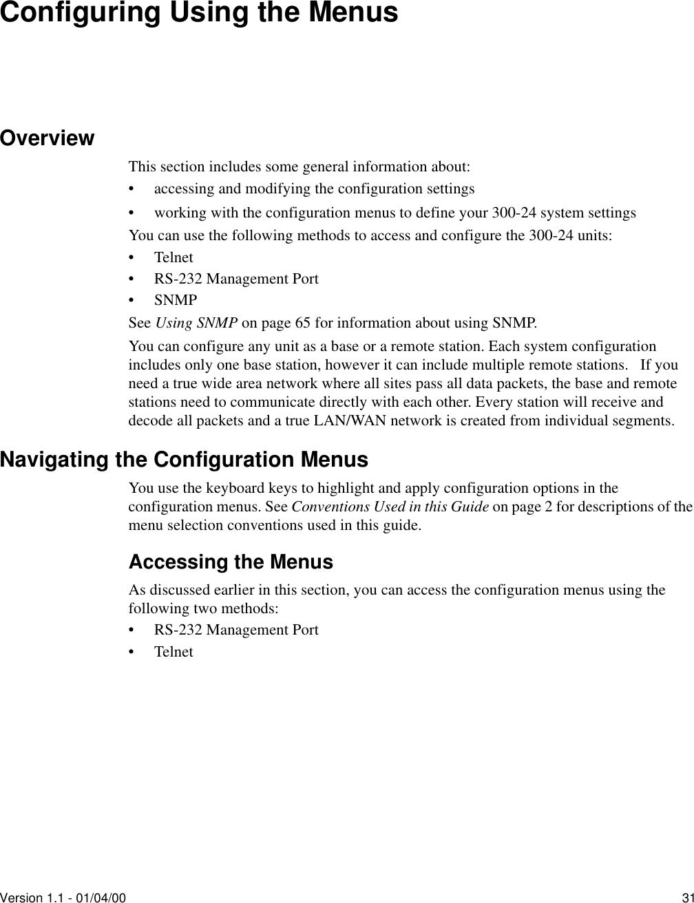
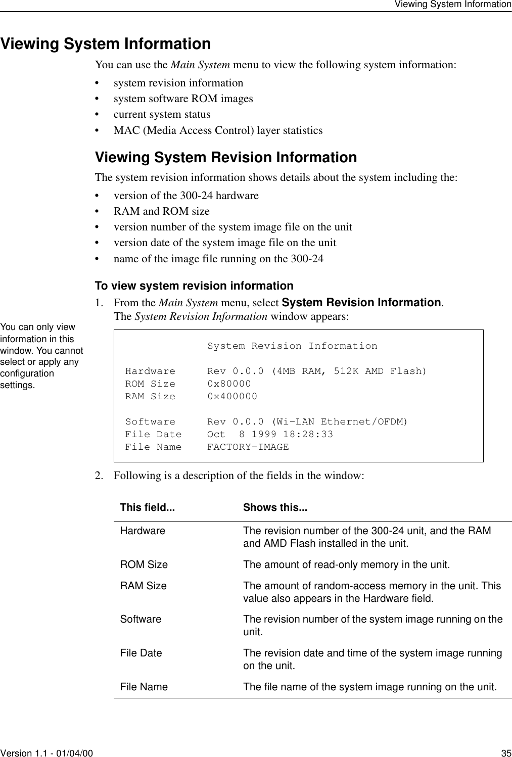
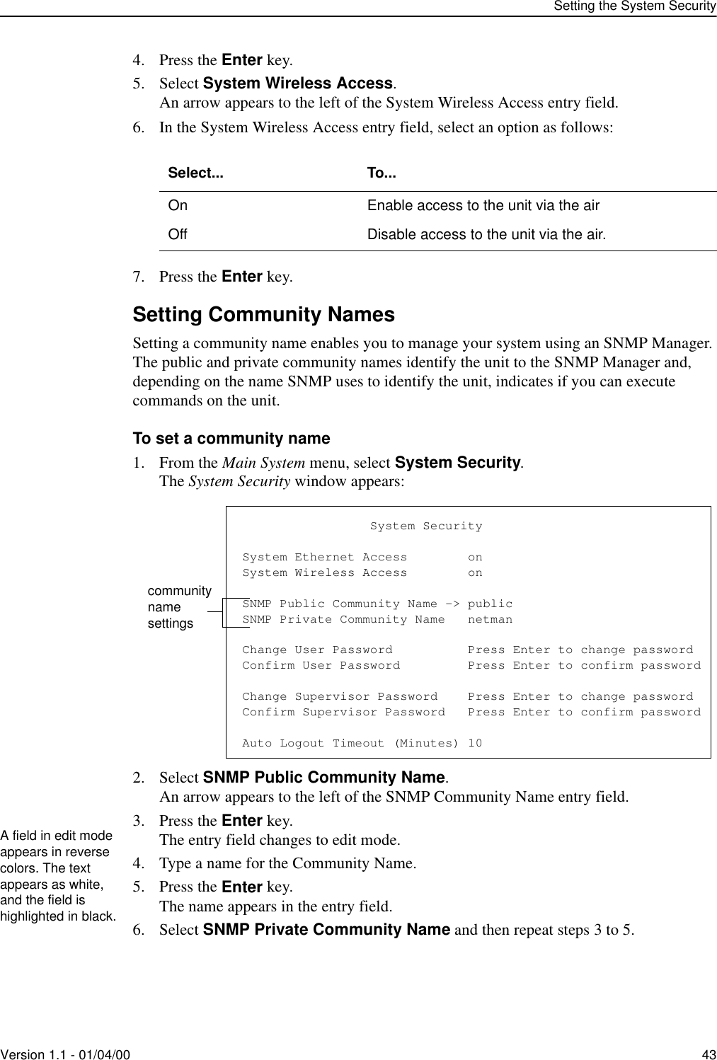
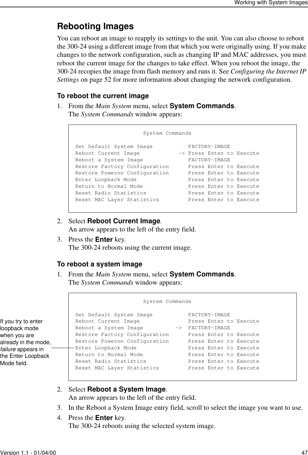
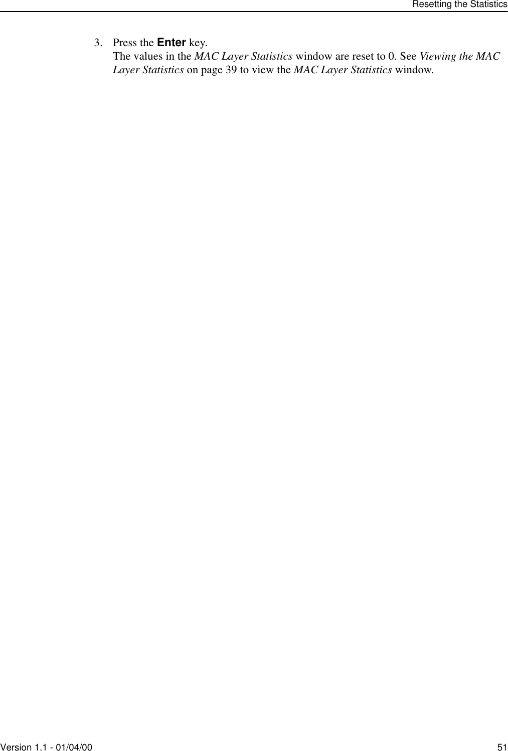
![Configuring Using the Menus58 Version 1.1 - 01/04/00Setting the RF IDs and Center FrequencyYou need to identify the RF station and network IDs for the unit, and also set the RF center frequency. All units in a given network should use the same frequency so they can communicate with each other.To set the RF Station ID1. From the Main System menu, select Radio Configuration.2. Press the Enter key.The Radio Configuration window appears:3. Select RF Station Id [0..1023].4. Press the Enter key.The entry field changes to edit mode.5. Type a unique number for the RF Station ID.6. Press the Enter key.The unit is assigned the RF Station ID.To set the RF Network ID1. From the Main System menu, select Radio Configuration.2. Press the Enter key.The Radio Configuration window appears:3. Select RF Network Id [0..1023].4. Press the Enter key.The entry field changes to edit mode.5. Type a unique number for the RF Network ID.6. Press the Enter key.The unit is assigned the RF Network ID. Radio ConfigurationOFDM Station Type Remote UnitRF Station Id [0..1023] -> 2RF Network Id [0..1023] 0RF Center Frequency 2.440 GHzEvery unit you configure must have a unique RF Station ID. No two units can have the same ID. Radio ConfigurationOFDM Station Type Remote UnitRF Station Id [0..1023] 2RF Network Id [0..1023] -> 0RF Center Frequency 2.440 GHz](https://usermanual.wiki/Wi-Lan/AP01.I-Will-30024-Manual/User-Guide-91098-Page-64.png)
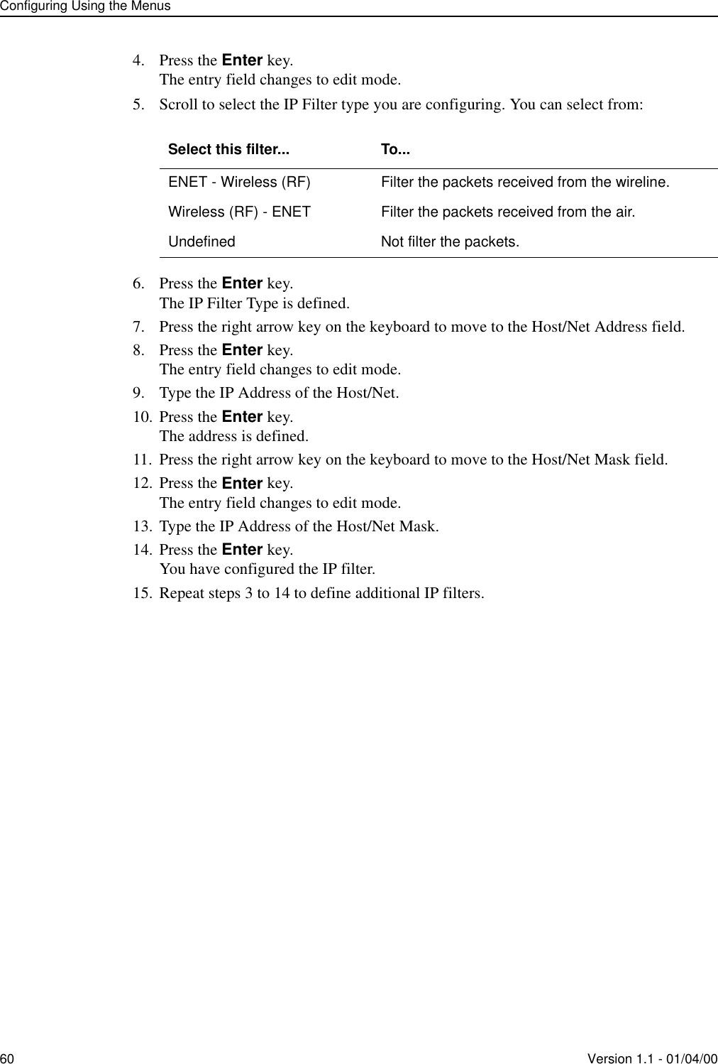
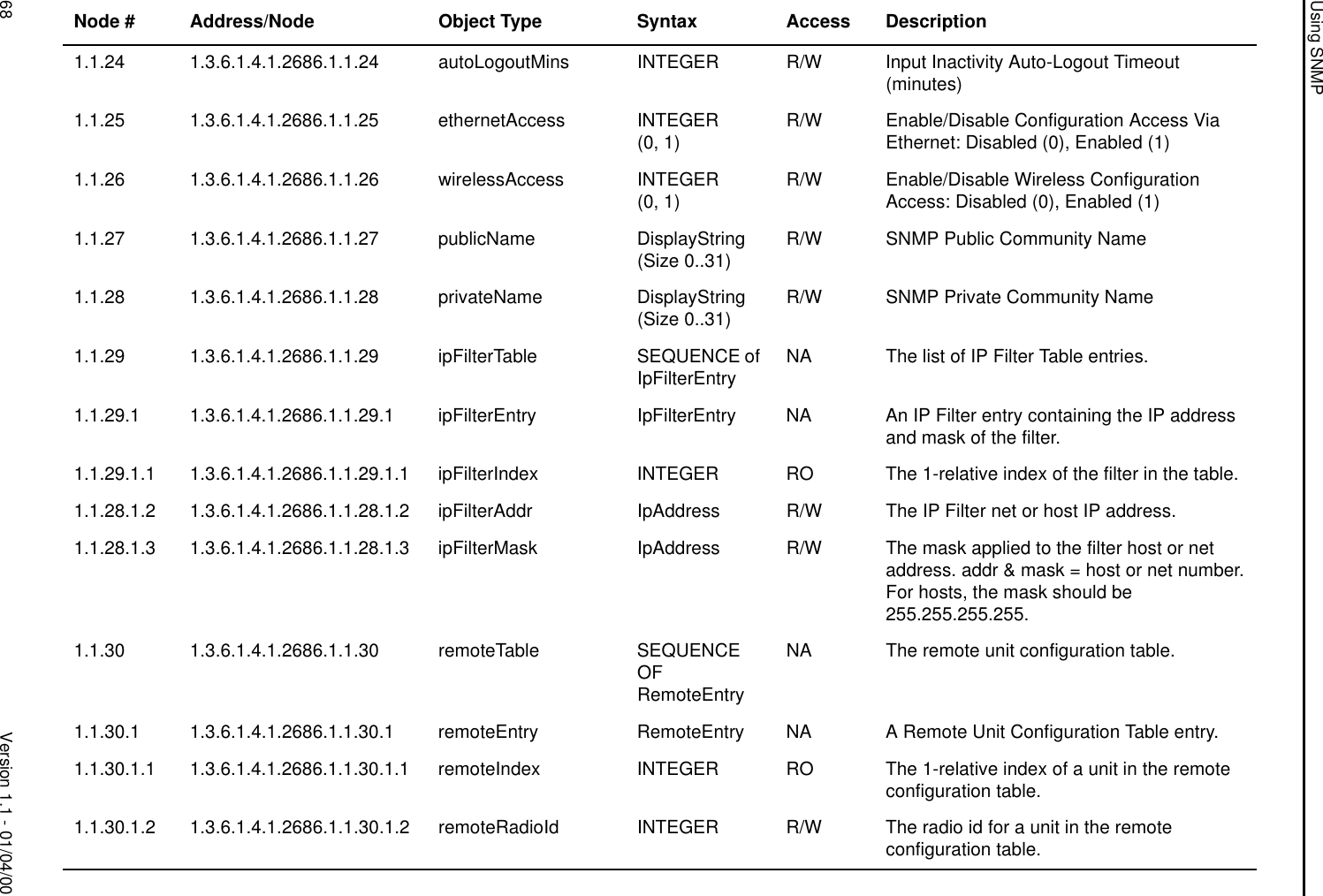
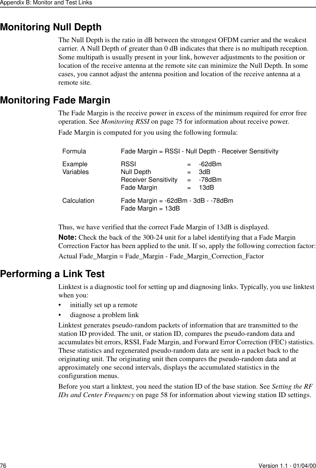
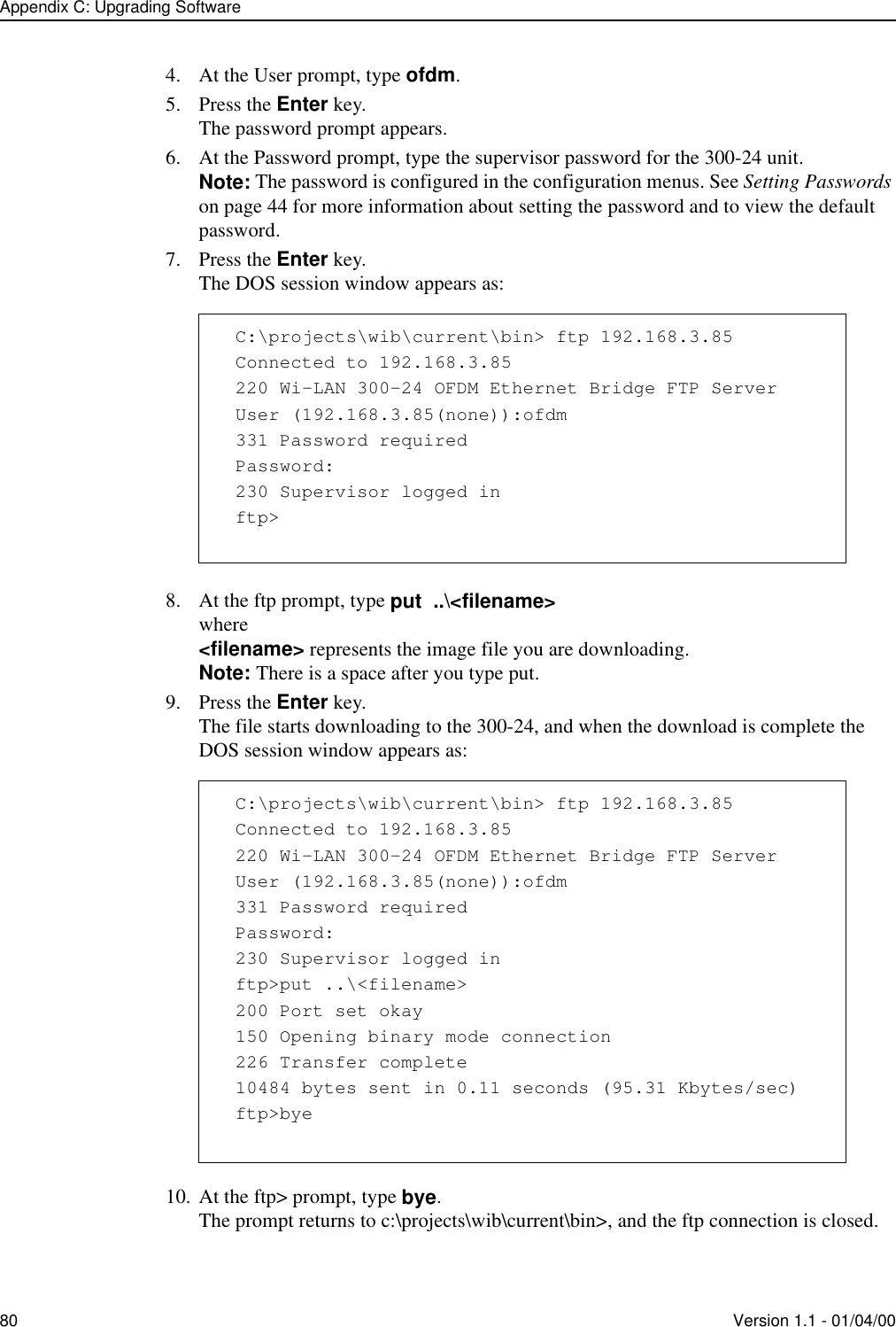
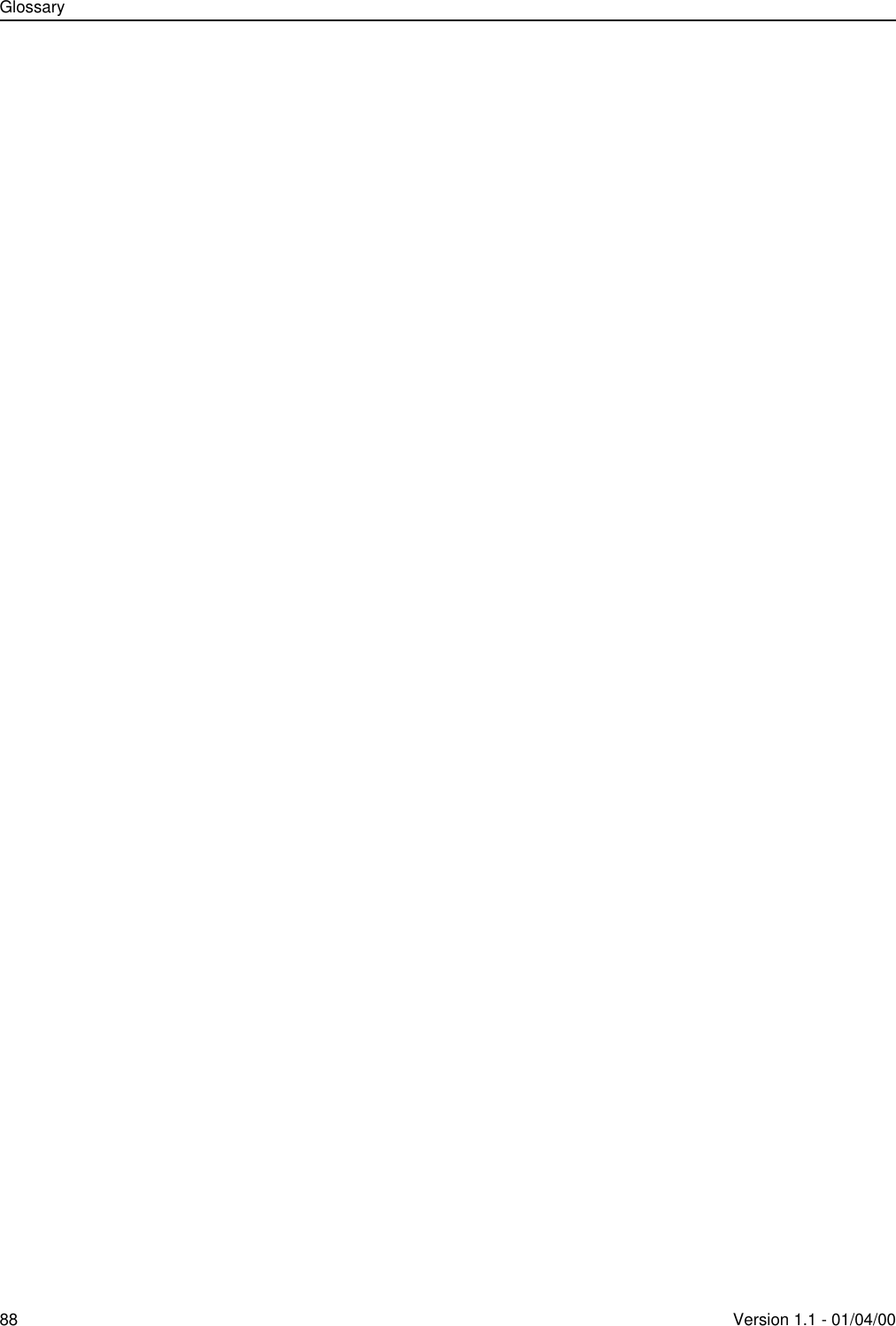
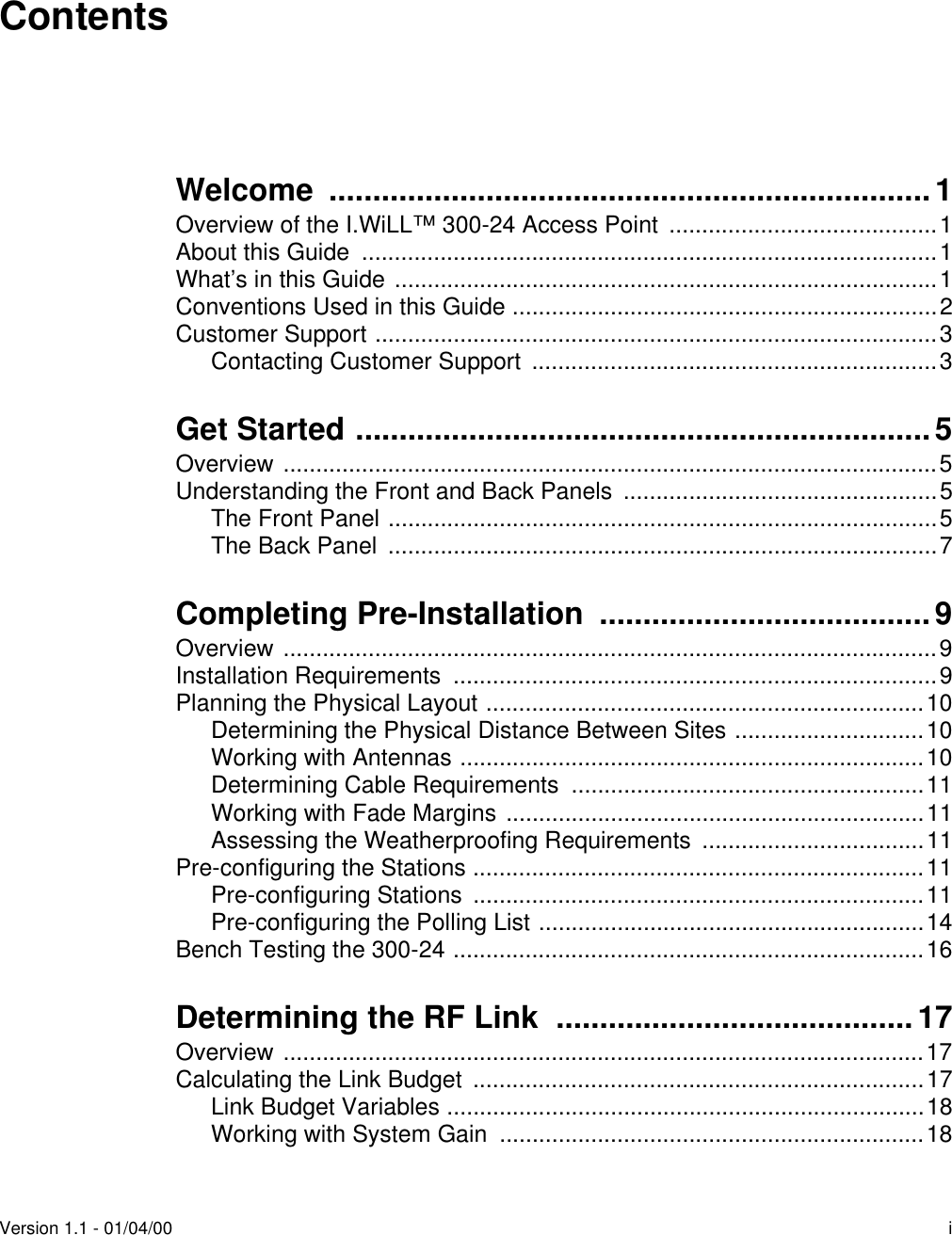
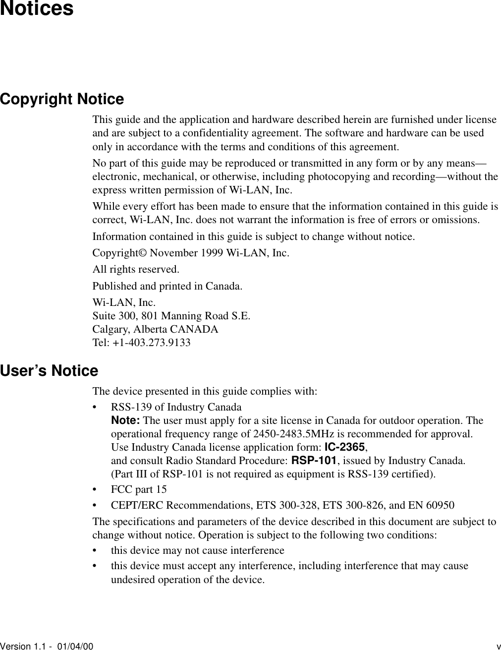
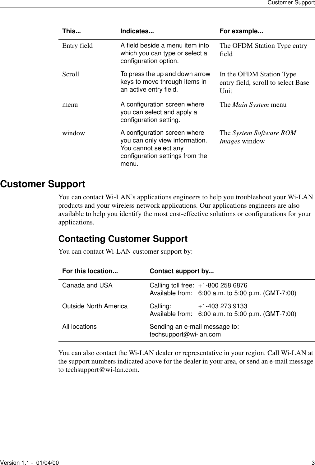
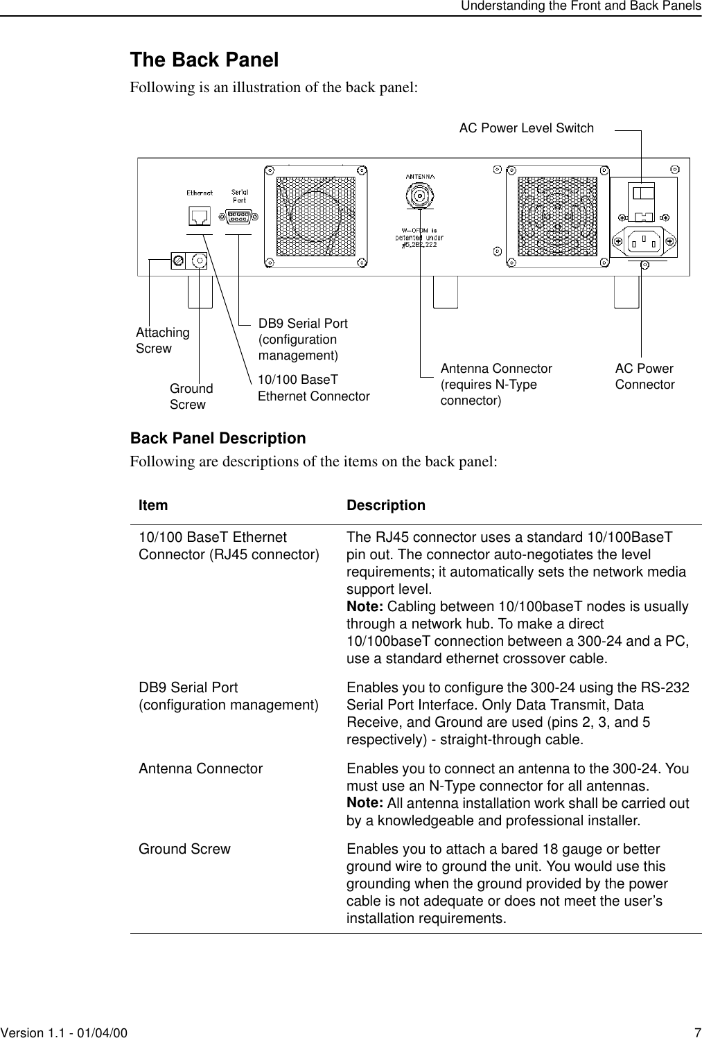
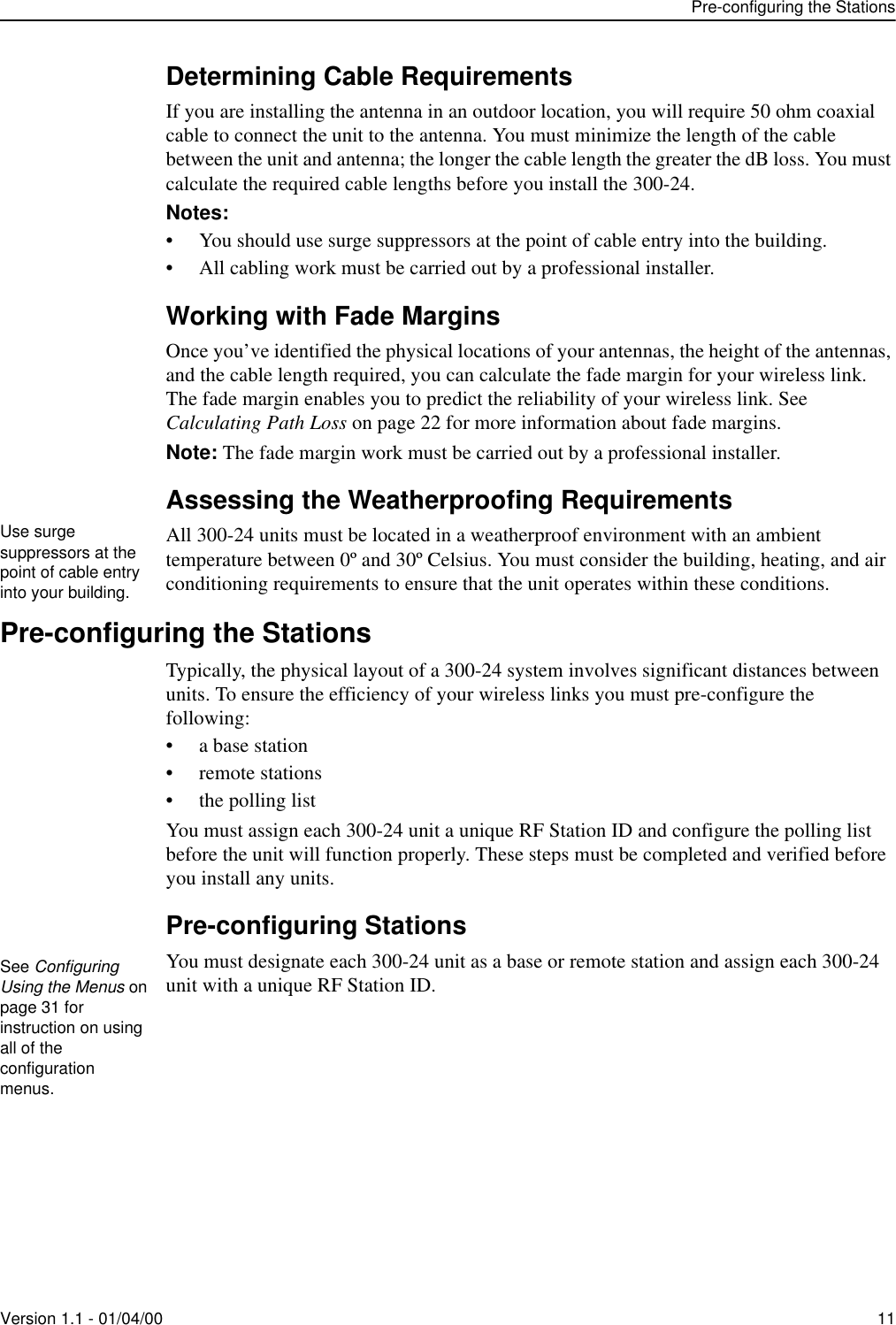
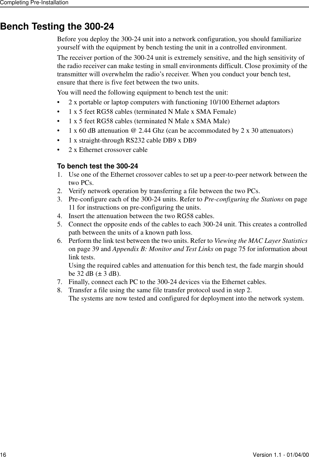
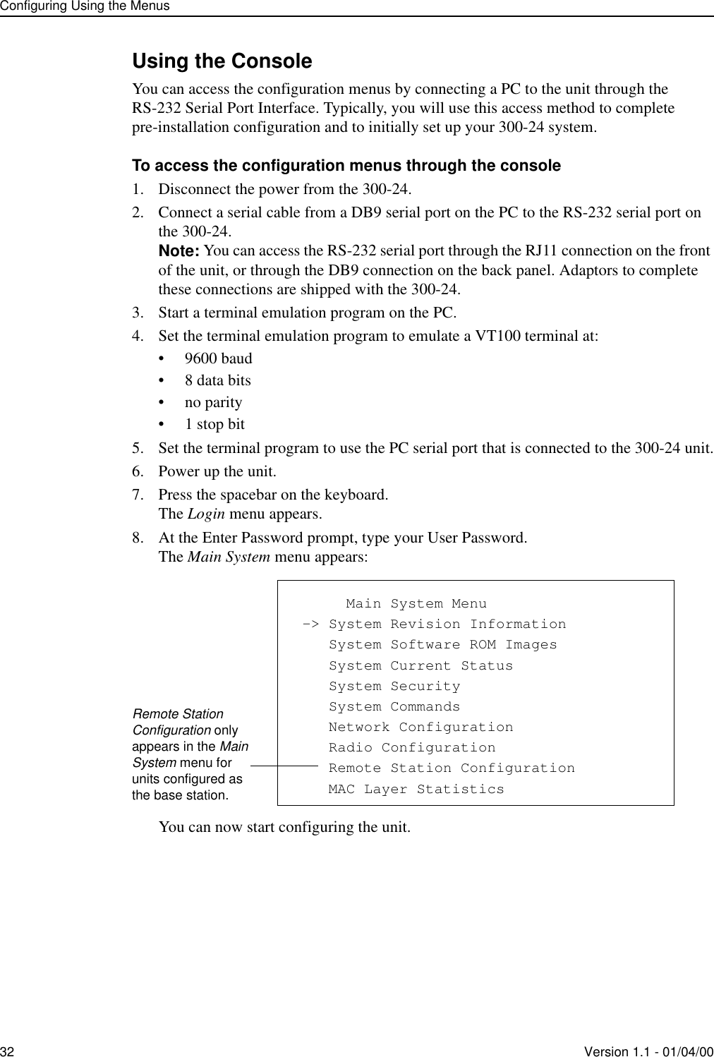
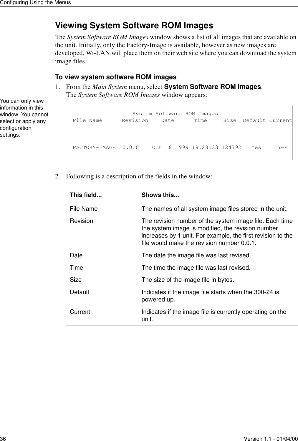
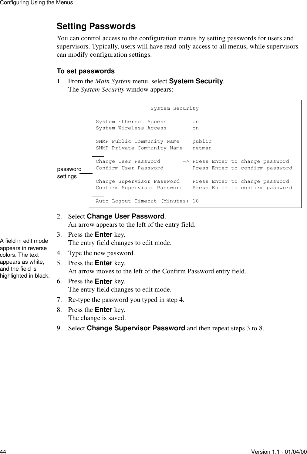
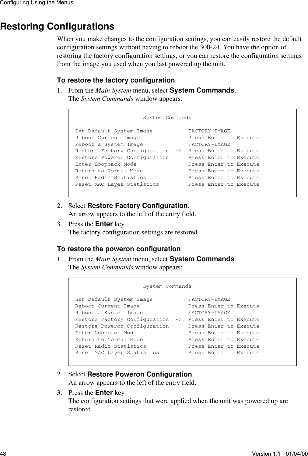
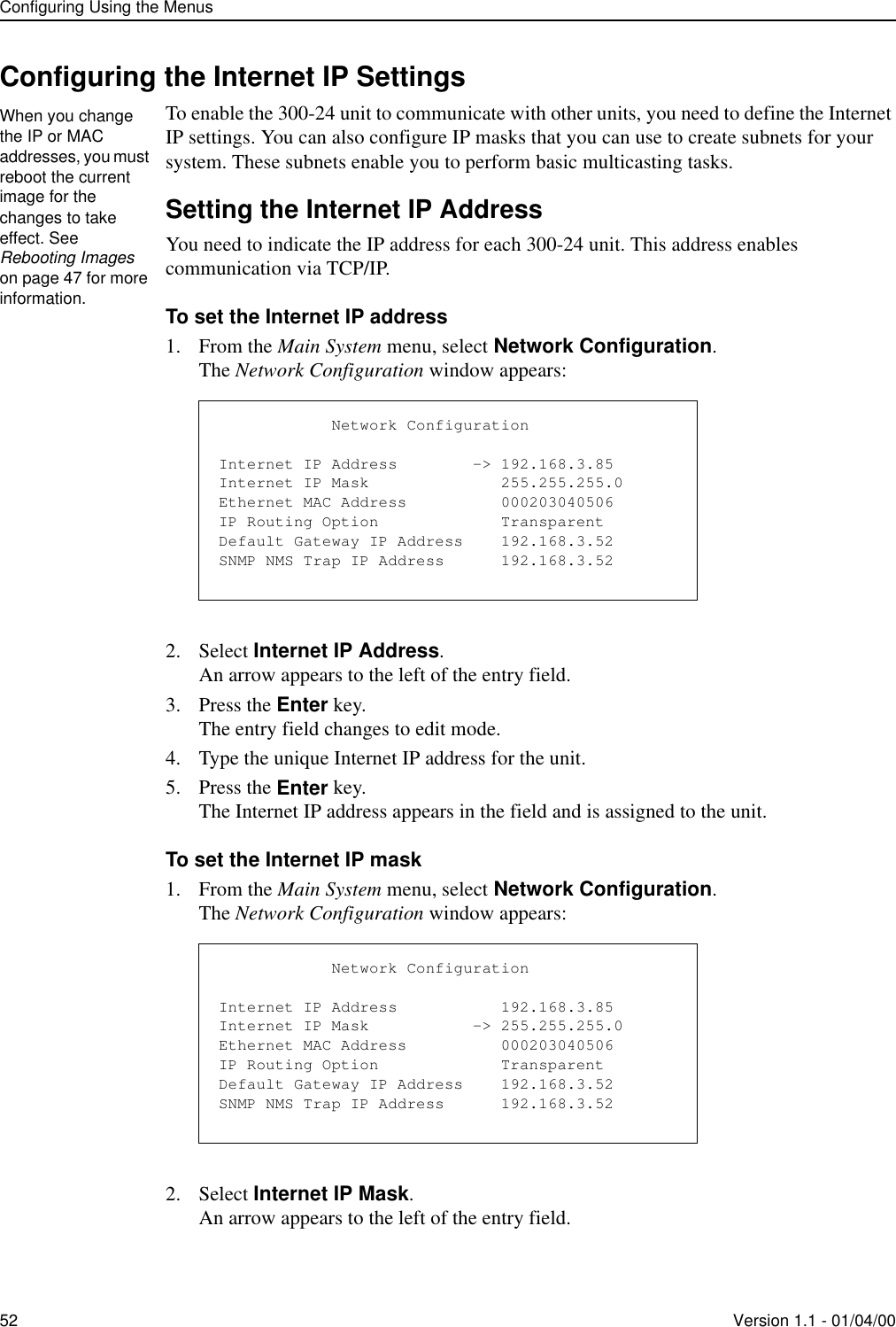
![Configuring the RadioVersion 1.1 - 01/04/00 59To set the RF center frequency1. From the Main System menu, select Radio Configuration.2. Press the Enter key.The Radio Configuration menu appears:3. Select RF Center Frequency.4. Press the Enter key.The entry field is highlighted.5. Scroll to select the RF center frequency you will apply to all units in the network.6. Press the Enter key.The center frequency is applied to the unit.Configuring the IP Filter for a Remote StationYou can create IP filters to filter the data that is transmitted and received through the 300-24 unit. The remote unit can filter packets received from the wire or air, or both. When you define a filter, you indicate the host and mask IP addresses of the packets that will be received and transmitted to the unit. To configure the IP filter for a remote station1. From the Main System menu, select IP Filter Configuration.2. Press the Enter key.The IP Filter Configuration window appears:3. Select the Undefined field in the Filter row you are defining.An arrow appears to the left of the field.To ensure communication between units, all units in the network must have the same center frequency. Radio ConfigurationOFDM Station Type Remote UnitRF Station Id [0..1023] 2RF Network Id [0..1023] 0RF Center Frequency -> 2.440 GHzYou can configure IP filters for only remote stations. IP Filter Configuration - Page 1 Filter Type Host/Net Address Host/Net Mask 1 ->Undefined 0.0.0.0 0.0.0.0 2 Undefined 0.0.0.0 0.0.0.0 3 Undefined 0.0.0.0 0.0.0.0 4 Undefined 0.0.0.0 0.0.0.0 5 Undefined 0.0.0.0 0.0.0.0 6 Undefined 0.0.0.0 0.0.0.0 7 Undefined 0.0.0.0 0.0.0.0 8 Undefined 0.0.0.0 0.0.0.0 9 Undefined 0.0.0.0 0.0.0.0 10 Undefined 0.0.0.0 0.0.0.0](https://usermanual.wiki/Wi-Lan/AP01.I-Will-30024-Manual/User-Guide-91098-Page-65.png)