Contents
- 1. I Will 30024 Manual
- 2. 300 24 Manual Replace Sheet
I Will 30024 Manual
Version 1.1 - 01/04/00 i
Contents
Welcome .....................................................................1
Overview of the I.WiLL™ 300-24 Access Point .........................................1
About this Guide ........................................................................................1
What’s in this Guide ...................................................................................1
Conventions Used in this Guide .................................................................2
Customer Support ......................................................................................3
Contacting Customer Support ..............................................................3
Get Started ..................................................................5
Overview ....................................................................................................5
Understanding the Front and Back Panels ................................................5
The Front Panel ....................................................................................5
The Back Panel ....................................................................................7
Completing Pre-Installation ......................................9
Overview ....................................................................................................9
Installation Requirements ..........................................................................9
Planning the Physical Layout ...................................................................10
Determining the Physical Distance Between Sites .............................10
Working with Antennas .......................................................................10
Determining Cable Requirements ......................................................11
Working with Fade Margins ................................................................11
Assessing the Weatherproofing Requirements ..................................11
Pre-configuring the Stations .....................................................................11
Pre-configuring Stations .....................................................................11
Pre-configuring the Polling List ...........................................................14
Bench Testing the 300-24 ........................................................................16
Determining the RF Link ......................................... 17
Overview ..................................................................................................17
Calculating the Link Budget .....................................................................17
Link Budget Variables .........................................................................18
Working with System Gain .................................................................18

Contents
ii Version 1.1 - 01/04/00
Calculating ERP (Effective Radiated Power) ..................................... 19
Working with Antenna Gain ............................................................... 19
Calculating Propagation Loss ............................................................ 20
Calculating Cable Loss ...................................................................... 21
Calculating Path Loss ........................................................................ 22
Link Budget Example .............................................................................. 23
Verifying a Link Budget ........................................................................... 24
Reviewing the Link Statistics ............................................................. 24
Installing Base and Remote Stations .....................27
Overview ................................................................................................. 27
Installing the Antenna .............................................................................. 27
Powering Up the Units ............................................................................. 27
Verifying the RF Port .......................................................................... 28
Fine-tuning Antennas ......................................................................... 29
Completing the Installation Connections ............................................ 29
Installing the Units on a Rack .................................................................. 30
Configuring Using the Menus .................................31
Overview ................................................................................................. 31
Navigating the Configuration Menus ....................................................... 31
Accessing the Menus ......................................................................... 31
Using the Console .............................................................................. 32
Using Telnet ....................................................................................... 33
Exiting the Configuration Menus ........................................................ 34
Viewing System Information .................................................................... 35
Viewing System Revision Information ................................................ 35
Viewing System Software ROM Images ............................................ 36
Viewing Current System Status ......................................................... 37
Viewing the MAC Layer Statistics ...................................................... 39
Setting the System Security .................................................................... 42
Setting Access Types ........................................................................ 42
Setting Community Names ................................................................ 43
Setting Passwords ............................................................................. 44
Setting Automatic Timeouts ............................................................... 45
Working with System Images .................................................................. 46
Setting the Default Image .................................................................. 46
Rebooting Images .............................................................................. 47
Restoring Configurations ......................................................................... 48
Working with Modes ................................................................................ 49
Resetting the Statistics ............................................................................ 50
Configuring the Internet IP Settings ........................................................ 52
Setting the Internet IP Address .......................................................... 52
Setting the Ethernet MAC Address .................................................... 53
Setting the IP Routing Options ........................................................... 54

Contents
Version 1.1 - 01/04/00 iii
Setting the Default Gateway IP Address ............................................55
Setting the SNMP NMS Trap IP Address ...........................................55
Configuring the Radio ..............................................................................57
Setting the OFDM Station Type ..........................................................57
Setting the RF IDs and Center Frequency .........................................58
Configuring the IP Filter for a Remote Station ....................................59
Configuring the Polling List .................................................................61
Using the 300-24 Command Line ............................................................63
Using the Basic Commands ...............................................................63
Using SNMP ..............................................................65
Using the Wi-LAN SNMP MIB ..................................................................65
Using the Wi-LAN MIB Object Identifier Nodes .......................................66
Wi-LAN MIB Object Identifier Nodes ..................................................67
Appendix A: Product Specification ........................73
Overview ..................................................................................................73
Specification .............................................................................................73
Appendix B: Monitor and Test Links ......................75
Overview ..................................................................................................75
Monitoring RSSI .......................................................................................75
Monitoring Null Depth ..............................................................................76
Monitoring Fade Margin ...........................................................................76
Performing a Link Test .............................................................................76
Appendix C: Upgrading Software ...........................79
Overview ..................................................................................................79
Upgrading Software via FTP ....................................................................79
Using the Upgraded Software ............................................................81
Glossary ....................................................................83
Index ..........................................................................89

Contents
iv Version 1.1 - 01/04/00
Version 1.1 - 01/04/00 v
Notices
Copyright Notice
This guide and the application and hardware described herein are furnished under license
and are subject to a confidentiality agreement. The software and hardware can be used
only in accordance with the terms and conditions of this agreement.
No part of this guide may be reproduced or transmitted in any form or by any means—
electronic, mechanical, or otherwise, including photocopying and recording—without the
express written permission of Wi-LAN, Inc.
While every effort has been made to ensure that the information contained in this guide is
correct, Wi-LAN, Inc. does not warrant the information is free of errors or omissions.
Information contained in this guide is subject to change without notice.
Copyright© November 1999 Wi-LAN, Inc.
All rights reserved.
Published and printed in Canada.
Wi-LAN, Inc.
Suite 300, 801 Manning Road S.E.
Calgary, Alberta CANADA
Tel: +1-403.273.9133
User’s Notice
The device presented in this guide complies with:
• RSS-139 of Industry Canada
Note: The user must apply for a site license in Canada for outdoor operation. The
operational frequency range of 2450-2483.5MHz is recommended for approval.
Use Industry Canada license application form: IC-2365,
and consult Radio Standard Procedure: RSP-101, issued by Industry Canada.
(Part III of RSP-101 is not required as equipment is RSS-139 certified).
• FCC part 15
• CEPT/ERC Recommendations, ETS 300-328, ETS 300-826, and EN 60950
The specifications and parameters of the device described in this document are subject to
change without notice. Operation is subject to the following two conditions:
• this device may not cause interference
• this device must accept any interference, including interference that may cause
undesired operation of the device.

Notices
vi Version 1.1 - 01/04/00
This equipment generates, uses, and radiates radio frequency and, if not installed and used
in accordance with this guide, may cause harmful interference to radio communications.
However, there is no guarantee that interference will not occur in a particular installation.
If this equipment does cause harmful interference to radio or television reception, which
can be determined by turning the equipment off and on, the user is encouraged to try to
correct the interference by one or more of the following methods:
• reorient or relocate the receiving antenna
• increase the separation between the equipment and receiver
• connect equipment to an outlet on a circuit different from that to which the receiver is
connected
• consult the dealer or an experienced radio/TV technician for help
As the 300-24 is used on a license-exempt, non-frequency coordinated, unprotected
spectrum allocation, and thus can be subject to random unidentified interference,
applications must not be those of a primary control where a lack of intercommunication
could cause danger to property, process, or person. An alternative fail-safe should be
designed into any system to ensure safe operation or shut down, should communication be
lost for any reason.
Important Notices
• Changes or modifications to the equipment not expressly approved by Wi-LAN, Inc.,
could void the user’s authority to operate the equipment.
• Appropriately shielded remote I/O serial cable with the metal connector shell and
cable shield properly connected to chassis ground shall be used to reduce the radio
frequency interference.
• FCC radio frequency exposure limits may be exceeded at distances closer than 23
centimeters from the antenna of this device.
• All antenna installation work shall be carried out by a knowledgeable and professional
installer.

Version 1.1 - 01/04/00 1
Welcome
Overview of the I.WiLL™ 300-24 Access Point
The I.WiLL™ 300-24 Access Point (300-24) is the first Wi-LAN product based on the
Wide-band Orthogonal Frequency Division Multiplexing (W-OFDM) technology. With a
peak data rate of 30 Mbps in 25 MHz of bandwidth, the 300-24 demonstrates the
industry’s most efficient use of bandwidth. The Dynamic Time Allocation technique
allocates variable time slots to busy stations when needed. Valuable bandwidth is not
wasted allocating time to idle stations.
The 300-24 operates in the 2.4-2.4835 GHz license-exempt ISM band allowing you to
provide wireless networking connectivity at a fraction of the wire, cable, or fibre
networking costs. You can manage, configure, and monitor the entire wireless network
through the RS-232 management port, SNMP, or telnet.
About this Guide
This guide provides instruction on how to install and configure your 300-24. The guide is
intended for individuals with basic experience installing and configuring
telecommunications and networking equipment. For assistance installing and configuring
the 300-24 contact Wi-LAN support. See Customer Support on page 3 for information
about contacting Wi-LAN.
What’s in this Guide
The following table shows the information in each section of this guide:
This section... Contains this information...
Welcome An overview of the 300-24, identifying who
should use this guide, how to obtain customer
support, and introducing the terms used in this
guide.
Get Started An introduction to the 300-24 front and back
panels, and a description of the LEDs and
connectors on the panels.
Completing Pre-Installation A list of the installation requirements,
instruction on how to complete preliminary
layout of your 300-24 system, including
working with antennas and fade margins, and
pre-configuring the unit.

Welcome
2Version 1.1 - 01/04/00
Conventions Used in this Guide
This guide uses specific typographic conventions to help you work with the guide when
you install and configure the 300-24. The following conventions are used:
Determining the RF Link Instruction on how to plan your RF link,
calculate the link budget, and an example of a
link budget calculation.
Installing Base and Remote Stations Instruction on how to install the base and
remote stations, including antenna installation,
rack installation, and working with the fade
margin.
Configuring Using the Menus Step-by-step instruction on configuring the
300-24 using the configuration menus.
Using SNMP A detailed description of the Wi-LAN SNMP
MIB object identifier nodes specific to the
300-24.
Appendix A: Product Specifications Specific technical details of the 300-24.
Appendix B: Monitor Link Mode Details about how to monitor the link mode
including monitoring the RSSI, null depth, and
fade margin.
Appendix C: Upgrading Software Instruction on how to upgrade the board
software using FTP.
Glossary An alphabetical list of the terms used in this
guide.
Index A detailed alphabetical index of this guide.
This section... Contains this information...
This... Indicates... For example...
italic text A configuration menu screen. Main System menu
bold arial A menu item you select or a key
you press on the keyboard. Select System Commands
or
Press the Enter key
bold serif Text that you type into a
configuration menu. On the command line, type
telnet <IP address>
Select To move the arrow cursor (->)
beside the menu item in the
configuration menu.
Select System Commands
Press To press a key on your
keyboard. Press the Enter key

Customer Support
Version 1.1 - 01/04/00 3
Customer Support
You can contact Wi-LAN’s applications engineers to help you troubleshoot your Wi-LAN
products and your wireless network applications. Our applications engineers are also
available to help you identify the most cost-effective solutions or configurations for your
applications.
Contacting Customer Support
You can contact Wi-LAN customer support by:
You can also contact the Wi-LAN dealer or representative in your region. Call Wi-LAN at
the support numbers indicated above for the dealer in your area, or send an e-mail message
to techsupport@wi-lan.com.
Entry field A field beside a menu item into
which you can type or select a
configuration option.
The OFDM Station Type entry
field
Scroll To press the up and down arrow
keys to move through items in
an active entry field.
In the OFDM Station Type
entry field, scroll to select Base
Unit
menu A configuration screen where
you can select and apply a
configuration setting.
The Main System menu
window A configuration screen where
you can only view information.
You cannot select any
configuration settings from the
menu.
The System Software ROM
Images window
This... Indicates... For example...
For this location... Contact support by...
Canada and USA Calling toll free: +1-800 258 6876
Available from: 6:00 a.m. to 5:00 p.m. (GMT-7:00)
Outside North America Calling: +1-403 273 9133
Available from: 6:00 a.m. to 5:00 p.m. (GMT-7:00)
All locations Sending an e-mail message to:
techsupport@wi-lan.com

Welcome
4Version 1.1 - 01/04/00
Version 1.1 - 01/04/00 5
Get Started
Overview
The I.WiLL™ 300-24 Access Point (300-24) is a multi-point product that allows wireless
connection of remote computers or LAN segments at signaling rates up to 30 Mbps. The
unit is self-contained and easy to use. You do not need installation disks or software
drivers to get started. You simply connect the 300-24 to each LAN segment.
This section introduces you to the front and back panels of the 300-24 and describes the
connectors and LEDs on the panels.
Understanding the Front and Back Panels
The 300-24 has connectors on the back and front panels that you need to be familiar with
before you install and configure the unit. You should also understand the color states of
the LEDs on the front panel.
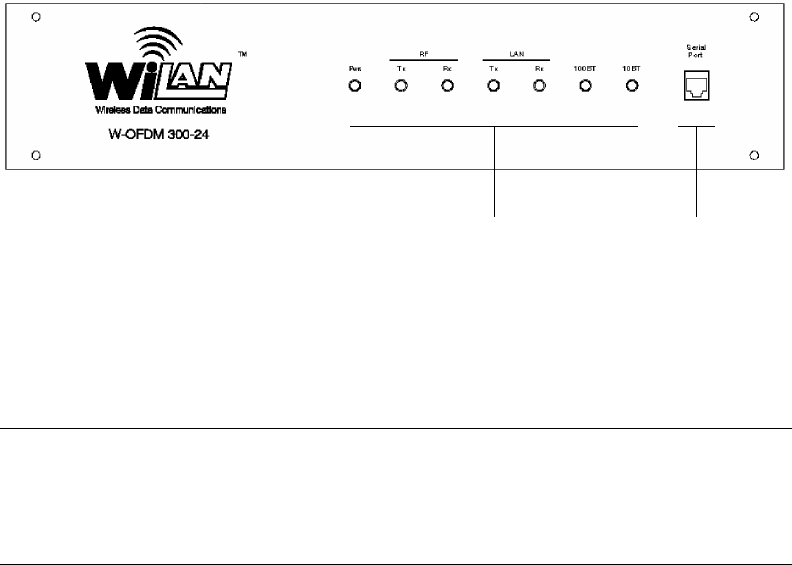
The Front Panel
Following is an illustration of the front panel:
Front Panel Description
Following is a description of the connector on the panel:
Connector Type Description
RJ11 Serial Port
Connector Enables you to configure the 300-24 using the RS-232 Serial
Port Interface. Only Data Transmit, Data Receive, and Ground
are used (pins 2, 3, and 5 respectively).
Note: You may have to use a male DB9 adaptor to connect to
the PC.
LED Indicators Serial Port
Connector

Get Started
6Version 1.1 - 01/04/00
Front Panel LEDs
The front panel has seven LEDs (Light Emitting Diodes) that indicate the normal
operational status of the transceiver. Following are the LED color states and their
associated status:
LED Type Color Status
Link - 10BT Green Active 10BaseT ethernet connection
Off Inactive 10BaseT ethernet connection
Link - 100BT Green Active 100BaseT ethernet connection
Off Inactive 100BaseT ethernet connection
LAN - Tx Green Transmitting to the wire (ethernet)
Off Inactive LAN Tx
LAN - Rx Green Receiving from the wire (ethernet)
Off Inactive LAN Rx
RF - Tx Green Transmitting to the air
Off Inactive RF Tx
RF - Rx Green Receiving from the air
Off Inactive RF Rx
Power Green Power is connected to the transceiver
Orange Power on self test
Off No power is connected to the
transceiver
During normal
operation, the Tx
and Rx LEDs blink.
Understanding the Front and Back Panels
Version 1.1 - 01/04/00 7
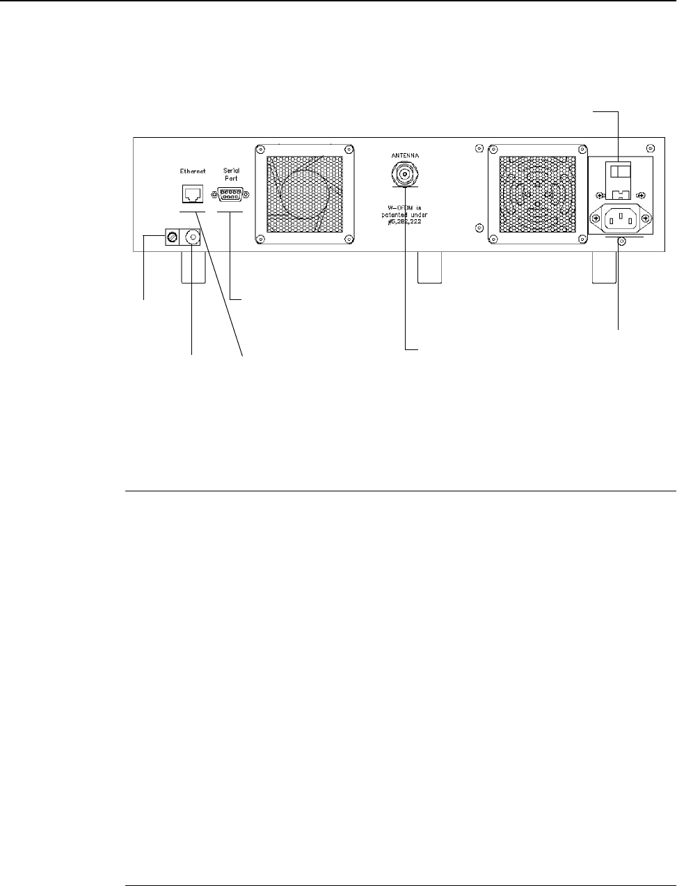
The Back Panel
Following is an illustration of the back panel:
Back Panel Description
Following are descriptions of the items on the back panel:
Item Description
10/100 BaseT Ethernet
Connector (RJ45 connector) The RJ45 connector uses a standard 10/100BaseT
pin out. The connector auto-negotiates the level
requirements; it automatically sets the network media
support level.
Note: Cabling between 10/100baseT nodes is usually
through a network hub. To make a direct
10/100baseT connection between a 300-24 and a PC,
use a standard ethernet crossover cable.
DB9 Serial Port
(configuration management) Enables you to configure the 300-24 using the RS-232
Serial Port Interface. Only Data Transmit, Data
Receive, and Ground are used (pins 2, 3, and 5
respectively) - straight-through cable.
Antenna Connector Enables you to connect an antenna to the 300-24. You
must use an N-Type connector for all antennas.
Note: All antenna installation work shall be carried out
by a knowledgeable and professional installer.
Ground Screw Enables you to attach a bared 18 gauge or better
ground wire to ground the unit. You would use this
grounding when the ground provided by the power
cable is not adequate or does not meet the user’s
installation requirements.
10/100 BaseT
Ethernet Connector
DB9 Serial Port
(configuration
management) Antenna Connector
(requires N-Type
connector)
AC Power
Connector
AC Power Level Switch
Attaching
Screw
Ground
Screw

Get Started
8Version 1.1 - 01/04/00
Grounding the 300-24
If the power cable used in your installation does not have adequate grounding, or if the
grounding does not meet your installation requirements, you will need to ground the unit
using the ground screw located on the back of the unit. This might occur if you you are
installing the unit on a rack, where solid chassis grounds are mandated by the installation
specialists. The ground wire should be 18 gauge or better and the other end of the wire
should be connected to the rack in the case of a rack mounted installation, or to the
customer’s facility grounding system. Following is an enlarged view of the ground screw
identified in The Back Panel on page 7:
When you ground the unit, you need to insert the ground wire into the hole for the ground
wire and then tighten the ground screw to secure the wire.
With a separate ground installed, the 300-24 may have a better earth ground than the local
AC power outlets; an isolation transformer or laptop PC may be required if ground loop
noise becomes troublesome. Proper electrostatic precautions must be followed.
ground screw
Rear View
Side View
hole for ground
wire
ground
screw
Version 1.1 - 01/04/00 9
Completing Pre-Installation
Overview
Before you install the I.WiLL™ 300-24 Access Point (300-24) you must perform certain
preliminary steps to ensure an effective and reliable wireless link. These steps include:
• gathering your required installation tools, accessories, and power supplies
• determining the physical layout of your planned link
• planning your antenna and fade margin requirements
• pre-configuring the stations
• bench testing the units in a controlled environment
Each of these steps is described in this section.
Installation Requirements
Before you install the 300-24, you should have the following tools and accessories
available:
• 10-32 x 3/4 Phillips oval head screws with plastic cup washers
(Hammond P/N 1421 A for rack mount)
• 50 ohm coaxial cable (outdoor installation site)
• Allen Hex Driver/Allen Key 5/64"
• Robertson No. 0 screwdriver
• EPROM extractor for PLCC package
• EPROM extractor for DIP package
• Nut driver 3/16"
Ensure that the 300-24 shipping package contains the following items:
• rubber duck antenna
• N-Type male to TNC female adaptor (for installing the rubber duck antenna)
• DB9 adaptor (F) to 6 cond (RJ11)
• power supply cord
• straight-through ethernet cable (RJ45)
• crossover ethernet cable (RJ45)
• DB9 (M) to DB25 (F) adaptor
• RJ11 serial port cable (14’ modular plug)
• RS-232 DB9 serial cable

Completing Pre-Installation
10 Version 1.1 - 01/04/00
• I.WiLL™ 300-24 Access Point Installation and Configuration Guide
• Wi-LAN Documentation CD
• Warranty Card
If any of the above items are not included in the 300-24 shipping package, please contact
Wi-LAN customer support. See Customer Support on page 3 for information on how to
contact Wi-LAN.
Planning the Physical Layout
Before you install the units, you must determine the physical locations for each
component of your 300-24 system. When you plan the physical layout, you will need to:
• use a GPS, map, or other distance measurement method to determine the physical
distance between each unit
You must have a professional installer assess and calculate the following:
• the antenna mast height requirements and fade margins
• the cable requirements including routing, between antenna and unit
• the fade margin to determine the reliability of your wireless link
• the weatherproofing requirements
Determining the Physical Distance Between Sites
Before you install the units, use a mapping method to determine the distance between your
sites. When you determine the distance, you must check the radio path to identify any
obstructions in the site path between radio locations. You can contact a Wi-LAN
applications engineer to confirm that you have planned an effective radio layout. See
Customer Support on page 3 for more information about contacting Wi-LAN.
Working with Antennas
If you are installing the unit in an indoor setting, the antenna packaged with the unit will
be sufficient for indoor wireless communications. If you are installing the unit in an
outdoor location, a professional installer must calculate the required mast height to ensure
effective communication between your radio links. When installing an outdoor antenna,
the professional installer should consider:
• the required height of the antenna to ensure a clear line-of-site between the RF links
• regulatory restrictions, such as height, on antenna mast usage in the identified location
• obtaining permission from building owners if you intend to install your antenna on a
rooftop
• potential wind load and ice loading impact on the antenna
• grounding requirements. The antenna must be properly grounded for lightening in
accordance with the relevant electrical code for the installation location.
See Working with Antenna Gain on page 19 or see the 300-24 Product Specification for
more information about installing and selecting antennas in outdoor locations.
Due to the high
frequency and low
output powers
permitted in the ISM
band, no
obstructions can be
tolerated between
two antennas.
You should use
lightening arrestors
to ground your
outdoor antenna,
cables, and support
structures.

Pre-configuring the Stations
Version 1.1 - 01/04/00 11
Determining Cable Requirements
If you are installing the antenna in an outdoor location, you will require 50 ohm coaxial
cable to connect the unit to the antenna. You must minimize the length of the cable
between the unit and antenna; the longer the cable length the greater the dB loss. You must
calculate the required cable lengths before you install the 300-24.
Notes:
• You should use surge suppressors at the point of cable entry into the building.
• All cabling work must be carried out by a professional installer.
Working with Fade Margins
Once you’ve identified the physical locations of your antennas, the height of the antennas,
and the cable length required, you can calculate the fade margin for your wireless link.
The fade margin enables you to predict the reliability of your wireless link. See
Calculating Path Loss on page 22 for more information about fade margins.
Note: The fade margin work must be carried out by a professional installer.
Assessing the Weatherproofing Requirements
All 300-24 units must be located in a weatherproof environment with an ambient
temperature between 0º and 30º Celsius. You must consider the building, heating, and air
conditioning requirements to ensure that the unit operates within these conditions.
Pre-configuring the Stations
Typically, the physical layout of a 300-24 system involves significant distances between
units. To ensure the efficiency of your wireless links you must pre-configure the
following:
•a base station
• remote stations
• the polling list
You must assign each 300-24 unit a unique RF Station ID and configure the polling list
before the unit will function properly. These steps must be completed and verified before
you install any units.
Pre-configuring Stations
You must designate each 300-24 unit as a base or remote station and assign each 300-24
unit with a unique RF Station ID.
Use surge
suppressors at the
point of cable entry
into your building.
See Configuring
Using the Menus on
page 31 for
instruction on using
all of the
configuration
menus.

Completing Pre-Installation
12 Version 1.1 - 01/04/00
Differences Between the Remote and Base Station Menus
The options that appear in the Main System menu vary depending whether you configured
the 300-24 unit as a base station or as a remote station. Following are the differences in the
Main System menu:
To configure a 300-24 unit as a base or remote station
1. Connect a computer to the 300-24 unit via the RS-232 serial port.
Note: The computer should be powered down when you connect it to the 300-24.
2. Power up the computer.
The Login menu appears.
3. At the Enter Password prompt, type your User Password.
Note: When you start the 300-24 unit for the first time, the following user names and
passwords apply:
4. Press the Enter key.
The Main System menu appears:
For this station type... This option appears... This option does not
appear...
Remote Station IP Filter Configuration Remote Station
Configuration
Base Station Remote Station
Configuration IP Filter Configuration
User Name Password Access Level
user user Read-only access
supervisor supervisor Read/write access
Main System Menu
-> System Revision Information
System Software ROM Images
System Current Status
System Security
System Commands
Network Configuration
Radio Configuration
IP Filter Configuration
MAC Layer Statistics
IP Filter
Configuration only
appears in the Main
System menu for
units configured as
remote stations.

Pre-configuring the Stations
Version 1.1 - 01/04/00 13
5. Select Radio Configuration.
6. Press the Enter key.
The Radio Configuration menu appears:
7. Select OFDM Station Type.
8. Press the Enter key.
The OFDM Station Type entry field is highlighted.
9. Complete the following steps depending on the type of station you are configuring:
10. Press the Enter key.
The unit is configured to the selected unit type.
11. Leave the Radio Configuration menu open.
To assign the base station or remote station an RF Station ID
1. In the Radio Configuration menu, select RF Station ID [0..1023].
2. Press the Enter key.
The RF Station ID entry field is highlighted.
3. Type a unique number for the RF Station ID.
4. Press the Enter key.
The unit is assigned the RF Station ID.
5. Make a note of the RF Station ID you assigned to the unit.
To configure a... Do this...
Base Station In the OFDM Station Type entry field, scroll to select
Base Unit.
Remote Station In the OFDM Station Type entry field, scroll to select
Remote Unit.
Use the up and
down arrow keys on
the keyboard to
select a menu item.
Radio Configuration
OFDM Station Type -> Remote Unit
RF Station Id [0..1023] 2
RF Network Id [0..1023] 0
RF Center Frequency 2.440 GHz
Radio Configuration
OFDM Station Type Remote Unit
RF Station Id [0..1023] -> 2
RF Network Id [0..1023] 0
RF Center Frequency 2.440 GHz
Every unit you
configure must have
a unique RF Station
ID. No two units can
have the same ID.

Completing Pre-Installation
14 Version 1.1 - 01/04/00
6. Press the Esc key until you exit the Configuration menu.
7. Power down the computer.
You have completed the pre-configuration for the unit.
8. Repeat the steps in To configure a 300-24 unit as a base or remote station and To
assign the base station or remote station an RF Station ID for each unit you need to
pre-configure.
Pre-configuring the Polling List
1. Connect a computer to the 300-24 unit you configured as a base station via the RS-232
serial port.
Note: The computer should be off when you connect it to the 300-24.
2. Power up the computer.
The Login menu appears.
3. At the Enter Password prompt, type your User Password.
Note: When you start the 300-24 unit for the first time, the following user names and
passwords apply:
4. Press the Enter key.
The Main System menu appears:
User Name Password Access Level
user user Read-only access
supervisor supervisor Read/write access
You pre-configure
the polling list for
only the base
station.
Main System Menu
-> System Revision Information
System Software ROM Images
System Current Status
System Security
System Commands
Network Configuration
Radio Configuration
Remote Station Configuration
MAC Layer Statistics
Remote Station
Configuration only
appears in the Main
System menu for
units configured as
the base station.
Pre-configuring the Stations
Version 1.1 - 01/04/00 15
5. Select Remote Station Configuration.
The Remote Station Configuration menu appears:
6. In the Radio Id field, type the Radio Station ID for the station (you must identify a
unique Radio Id for all remotes and the base station).
Note: The order in which you enter the IDs determines the polling sequence of the
units.
7. In the Distance field, type the distance, in meters, from the Radio ID to the base
station.
Following is an example of a completed polling list entry:
8. Once you have entered the ID and distance for each remote station and the base
station, press the Esc key until you exit the Configuration menu.
9. Power down the computer.
You have pre-configured the polling list.
The Remote Station
Configuration menu
is two pages. The
polling list can
contain up to 100
stations.
Remote Station Configuration - Page 1
Remote Radio Id Distance Remote Radio Id Distance Remote Radio Id Distance
Number 0..1023 0..9999 Number 0..1023 0..9999 Number 0..1023 0..9999
1 ->1 1900 2 2 1900 3 0 0
4 0 0 5 0 0 6 0 0
7 0 0 8 0 0 9 0 0
10 0 0 11 0 0 12 0 0
13 0 0 14 0 0 15 0 0
16 0 0 17 0 0 18 0 0
19 0 0 20 0 0 21 0 0
22 0 0 23 0 0 24 0 0
25 0 0 26 0 0 27 0 0
28 0 0 29 0 0 30 0 0
31 0 0 32 0 0 33 0 0
34 0 0 35 0 0 36 0 0
37 0 0 38 0 0 39 0 0
40 0 0 41 0 0 42 0 0
43 0 0 44 0 0 45 0 0
46 0 0 47 0 0 48 0 0
49 0 0 50 0 0 51 0 0
52 0 0 53 0 0 54 0 0
55 0 0 56 0 0 57 0 0
Remote Radio Id Distance
Number 0..1023 0..9999
1 ->1 1900
The station is the first item in the polling list.
The RF Station ID is 1.
The RF Station ID 1 is 1900 meters from the base station.

Completing Pre-Installation
16 Version 1.1 - 01/04/00
Bench Testing the 300-24
Before you deploy the 300-24 unit into a network configuration, you should familiarize
yourself with the equipment by bench testing the unit in a controlled environment.
The receiver portion of the 300-24 unit is extremely sensitive, and the high sensitivity of
the radio receiver can make testing in small environments difficult. Close proximity of the
transmitter will overwhelm the radio’s receiver. When you conduct your bench test,
ensure that there is five feet between the two units.
You will need the following equipment to bench test the unit:
• 2 x portable or laptop computers with functioning 10/100 Ethernet adaptors
• 1 x 5 feet RG58 cables (terminated N Male x SMA Female)
• 1 x 5 feet RG58 cables (terminated N Male x SMA Male)
• 1 x 60 dB attenuation @ 2.44 Ghz (can be accommodated by 2 x 30 attenuators)
• 1 x straight-through RS232 cable DB9 x DB9
• 2 x Ethernet crossover cable
To bench test the 300-24
1. Use one of the Ethernet crossover cables to set up a peer-to-peer network between the
two PCs.
2. Verify network operation by transferring a file between the two PCs.
3. Pre-configure each of the 300-24 units. Refer to Pre-configuring the Stations on page
11 for instructions on pre-configuring the units.
4. Insert the attenuation between the two RG58 cables.
5. Connect the opposite ends of the cables to each 300-24 unit. This creates a controlled
path between the units of a known path loss.
6. Perform the link test between the two units. Refer to Viewing the MAC Layer Statistics
on page 39 and Appendix B: Monitor and Test Links on page 75 for information about
link tests.
Using the required cables and attenuation for this bench test, the fade margin should
be 32 dB (± 3 dB).
7. Finally, connect each PC to the 300-24 devices via the Ethernet cables.
8. Transfer a file using the same file transfer protocol used in step 2.
The systems are now tested and configured for deployment into the network system.

Version 1.1 - 01/04/00 17
Determining the RF Link
Overview
This section provides details about how to obtain the maximum range from your RF link.
The effectiveness and reliability of your RF link depends on the following:
• antenna gain
• distance between antennas and obstructions in the RF path
• above-ground height of the antennas
• length and type of coaxial cable connecting the 300-24 and the antenna
The above factors are used to calculate your link budget. The link budget calculation
indicates if your radio link is feasible over a given distance and path and if your RF link
meets regulatory requirements. Link budgets are typically expressed in decibel (dB)
format.
Calculating the Link Budget
Specific calculations must be completed to determine your link budget. This section
describes the calculations and includes definitions of the terms and variables used in the
calculations. The following dB terms are used in this section:
Term Description
dB Decibel. A relative measure of power used to specify power
gains and losses. The difference in power P1 and P2
expressed in dB is:
dBd The gain or loss of an antenna reference to a standard dipole.
Gain of a Standard Dipole = 2.14 dBi.
dBi The gain or loss of an antenna referenced to an isotropic
(theoretical point source) radiator. This measure is used with
only antennas, as it quantifies gain or loss of a physical
radiator with respect to a theoretical one.
dBm A power measurement referenced to one milli-Watt. This is an
absolute measure of power rather than a relative measure
such as a gain or a loss.
dB 10 P1
P2
-------
log×=

Determining the RF Link
18 Version 1.1 - 01/04/00
Link Budget Variables
You will use the following variables when you calculate the link budget:
Working with System Gain
Proper path planning ensures that each end of the RF link receives sufficient signal power
to maintain a desired Bit Error Rate (BER). The system gain of a radio system is the
difference between the transmitted power and the receiver’s sensitivity threshold. See Link
Budget Variables on page 18 for definitions of these terms. Using this relationship, the
system gain of the 300-24 is:
Variable Description
System Gain The maximum path loss that the system can support
for usable data transmission.
ERP (Effective Radiated
Power) The power radiating from an antenna taking into
account the output power from the transmitter,
connector losses, cable losses, and the antenna
gain.
Sensitivity The minimum signal strength required for usable
performance. Expressed in dBm.
Antenna Gain Gain of the antenna over a dipole (dBd) or
theoretical (dBi).
Propagation Loss The signal loss experienced as it travels through the
air. Expressed in dB.
Cable Loss The signal loss experienced as it passes through the
coax cable. Expressed in dB.
Path Loss The total loss from one end of the path to the other.
This includes propagation losses, cable losses, and
any other losses that impact the system
performance.
Formula: System Gain = Tx Power - Rx Sensitivity
Variables: Tx Power = 15dBm
Receiver Sensitivity = -78dBm nominal for quasi-error free
(BER 10-9) operation
Calculation: 93dB = 15dBm - -78dBm
More info: To ensure reliable communications, the system gain plus all antenna
gains must be greater than the sum of all losses. For a reliable link it
is recommended that the system gain plus all antenna gains be
greater than the sum of all losses by a factor of 13dB. This factor is
known as the Fade Margin.

Calculating the Link Budget
Version 1.1 - 01/04/00 19
Calculating ERP (Effective Radiated Power)
ERP is the power radiating from an antenna taking into account the output power from the
transmitter, the connector and cable losses, and the antenna gain. Because many antennas
can provide a directional gain, the effective radiated power can increase. Losses, such as
cable losses can subtract from this amount. You calculate the ERP as follows:
Note: All ERP work must be completed by a professional installer.
Working with Antenna Gain
To ensure the best range and interference suppression, the external antenna should be
directional, focusing the radio energy in one direction (toward the other end of the link).
The direction can be azmuthal or a horizontal radiation angle. A directional antenna
focuses the RF energy to the intended station rather than omni-directionally. This reduces
interference from other systems that are operating at the same frequency.
Note: In some situations, you may want to use an omni-directional antenna in your
system design. For example, you would use an omni-directional antenna for a base station
with remote sites situated in a 360º path around it.
When you select an antenna, pay particular attention to the gain specification. When you
select an antenna for a remote station, select an antenna with a gain that provides at least
13dB Fade Margin.
Antenna gain is specified in either dBi or dBd. When an antenna is specified in dBd, add
2.14dB to the value to convert it to dBi.
Note: All antenna gain work must be completed by a professional installer.
Formula: ERP = Tx Power (dBm) - Cable Losses (dBm) - Connector Losses
(dBm) + Antenna Gain (dB)
Note: The FCC regulatory body has set the ERP limit to +36dBm for fixed
point-to-point applications per FCC 15.247(b)(3)(i).
Industry Canada RSS-139, Annex B specifies the maximum
transmitter output at +30dBm, with a maximum EIRP (Equivalent
Isotropically Radiated Power) at +36dBm for multi-point
configurations and a maximum EIRP of +53dBm only for licensed
point-to-point applications.
In accordance with ETS 300-328 for 2.4GHz RLANs, the maximum
EIRP shall not exceed +20dBm, with a maximum SPD (Spectral
Power Density) not exceeding +10dBm/MHz. Confirmation is
required with the relevant European national radio communications
local authority for deviations from this specification.
Unlike the Tx output
power of the
devices, ERP is
subject to both
antenna gain and
cable losses.

Determining the RF Link
20 Version 1.1 - 01/04/00
Calculating Propagation Loss
The propagation loss is the attenuation (reduction) in RF signal energy as it travels
through space. In most wireless systems, losses through space are the major contributor to
signal attenuation. When you know the intended installation locations of the base and
remote stations, determine the physical line of sight distance and then calculate the RF
attenuation as follows:
Note: All propagation loss work must be completed by a professional installer.
Working with the Fresnel Zone
It is essential to locate your antennas at maximum above-ground height to ensure the most
effective and reliable link. Achieving maximum above-ground antenna height means that:
• all ground-based obstructions are cleared from the line-of-sight path
• the Fresnel Zone is clear of obstructions
Formula: Attenuation (dB) = 100dB + 20log(dkm)
where:
dkm = Distance in Kilometers
100dB = Pathloss Constant
Note: The FCC regulatory body has set the ERP limit to +36dBm for fixed
point-to-point applications per FCC 15.247(b)(3)(i).
Industry Canada RSS-139, Annex B specifies the maximum
transmitter output at +30dBm, with a maximum EIRP (Equivalent
Isotropically Radiated Power) at +36dBm for multi-point
configurations and a maximum EIRP of +53dBm only for licensed
point-to-point applications.
In accordance with ETS 300-328 for 2.4GHz RLANs, the maximum
EIRP shall not exceed +20dBm, with a maximum SPD (Spectral
Power Density) not exceeding +10dBm/MHz. Confirmation is
required with the relevant European national radiocommunications
local authority for deviations from this specification.
Calculating the Link Budget
Version 1.1 - 01/04/00 21
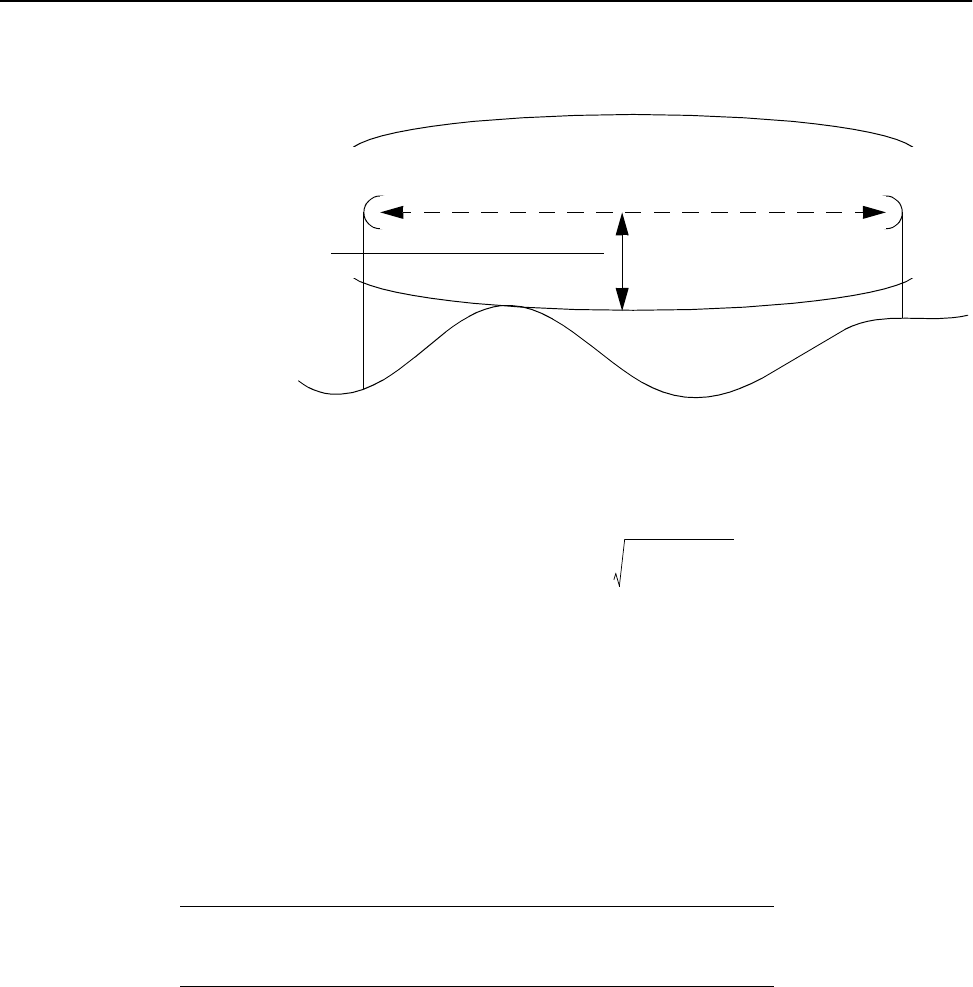
The Fresnel Zone is the expansion of the RF signal radio angles in the vertical plane near
the middle of the RF path. Following is a basic illustration of the Fresnel Zone concept:
The Fresnel radius is calculated as follows:
Calculating Cable Loss
The wireless link is subject to implementation losses such as cable and connector losses.
The two primary coaxial cable specifications for the 300-24 are:
• cable must be 50 ohms nominal impedance
• cable must be of a low loss type
Generally, cable losses are specified in dB/foot or dB/meter. Following is an example of
cable loss ratings:
Notes:
• When you calculate path loss, you should add 1dB at each end of the link to
compensate for connector losses in addition to the cable loss value.
• All cable loss work must be completed by a professional installer.
Formula: Fresnel Zone Radius =
Cable Type dB/foot dB/meter
LMR400 0.0684 0.220
LMR600 0.0441 0.142
First Fresnel Zone
Line of Sight
Fresnel Radius
Ground
The maximum
Fresnel Radius
indicates that this
path must be kept
clear of
obstructions.
3.4 dkm d
8.12
-----------
2
+
×metres
I
ns
t
a
ll
a
ti
ons
involving cable runs
longer than a few
feet must use high-
quality, low loss
shielded coax.

Determining the RF Link
22 Version 1.1 - 01/04/00
Calculating Path Loss
Path loss describes the total RF attenuation throughout the system from Tx antenna to Rx
antenna. This includes the losses as the RF signal travels through space plus Tx and Rx
cable loss, and Tx and Rx connector loss. Use the following formula to calculate path loss:
Once you know the path loss, you can compare the value to the system gain value. If the
system gain value is greater than the path loss, the link is feasible. See Working with
System Gain on page 18 for more information about system gain.
Note: All path loss work must be completed by a professional installer.
Working with the Fade Margin
The amount that the system gain plus the total antenna gain exceeds the path loss is called
the Fade Margin. The Fade Margin is calculated as the number of dB that the received
signal strength exceeds the minimum receiver sensitivity. You require some level of Fade
Margin for any wireless system. The Fade Margin compensates for RF path fading due to
weather conditions or nearby objects that induce multi-path signaling.
The Fade Margin for the 300-24 is a minimum of 13dB. The sum of the cable losses,
connector losses, propagation losses, and the 13dB required Fade Margin should be less
than the system gain value of 93dB.
Note: All fade margin work must be completed by a professional installer.
Formula: Path Loss = Tx and Rx Cable Loss + Tx and Rx Connector Loss +
Propagation Loss
Total antenna gain
is:
Tx Antenna Gain +
Rx Antenna Gain

Link Budget Example
Version 1.1 - 01/04/00 23
Link Budget Example
Putting everything together, you must satisfy the following equation to have a successful
link:
Formulas: System Gain + Antenna Gain ≥ Propagation Loss + Fade Margin
+ Cable Losses + Connector Losses
or Fade Margin ≥ System Gain + Antenna Gain - Propagation Loss -
Cable Losses - Connector Losses
where:
System Gain = Tx Power - Rx Sensitivity
Antenna Gains = Tx Antenna Gain + Rx Antenna Gain
Cable Losses = Base Cable Losses + Remote Cable Losses
Connector Losses = Base System Connector Losses + Remote
System Connector Losses
Variables: Desired Fade Margin = 13dB
Tx Power = 15dBm
Rx Sensitivity = -78dBm
Tx Antenna Gain = 9dB
Rx Antenna Gain = 15 dB
Propagation Loss for
desired range of 1km =
Tx Cable Losses
(2m LMR400) = .44dB
Rx Cable Losses
(2m LMR 400) = .44dB
Tx Connector Losses = .5dB
Rx Connector Losses = .5dB
Variable
Calculations: System Gain = 15dBm - -78dBm = 93dBm
Antenna Gains = 9dB + 15dB = 24dB
Cable Losses = .44dB + .44dB = .88dB
Connector Losses = .5dB + .5dB = 1dB
Fade Margin
Calculation: Fade Margin = 93dB + 24dB - 100dB - .88dB - 1dB = 15.12dB
Analysis: We have achieved the goal of a Fade Margin ≥ 13dB.
The values for cable
and connector
losses in this
example are only for
illustration. You will
need to work these
out for your specific
installations.
100 20 1〈〉log×
+100dB
=

Determining the RF Link
24 Version 1.1 - 01/04/00
Verifying a Link Budget
To verify the link budget calculations, from the 300-24 user interface, measure the
Received Signal Strength Indicator (RSSI), Null Depth, and the Fade Margin.
Note: The effects of multi-path are not the same in both directions of a link and you need
to verify the link budget in both directions.
Following are descriptions of the link statistics you need to measure:
Reviewing the Link Statistics
Once you set up the link and select the Mac Layer Statistics window in the user interface,
you can measure the RSSI, Null Depth, and Fade Margin to ensure that the link is
functioning properly. See Appendix B: Monitor and Test Links on page 75 for more
information about monitoring link statistics after the system installation is complete.
You need to measure:
• Null Depth
• Bit Error Rate (BER)
Interpreting the Null Depth
When you interpret the link statistics, you need to subtract the Null Depth from your
budgeted Fade Margin. For example, if you budgeted a 13dB Fade Margin, and you have
an indicated Null Depth of 3dB and an indicated Fade Margin of 10dB, then your
calculations were correct.
Budgeted Fade Margin = Indicated Null Depth + Indicated Fade Margin
where:
13dB = 3dB + 10dB
For small Null Depths, you will typically proceed with a reduced Fade Margin as long as
the number of uncorrected errors is zero, or is incrementing very slowly during peak
traffic periods.
Term Description
Null Depth The difference in strength between the strongest and weakest
OFDM carriers. A Null Depth of more than a few dB indicates the
receiver is experiencing multi-path effects which are partially
canceling the signal. If the Null Depth is more than 3dB, it should
be compensated by moving the receiving antenna or increasing
the antenna gain.
RSSI A numeric indication of the received signal strength in dBm.
You need to verify
the link budget in
both directions: base
station to remote
station and remote
station to base
station.
See Viewing the
MAC Layer
Statistics on page 39
for more information
about the MAC
Layer Statistics
window.

Verifying a Link Budget
Version 1.1 - 01/04/00 25
Interpreting Bit Error Rate (BER)
The BER after Reed-Solomon Forward Error Correction (RS FEC) can be computed from
the number of uncorrected byte errors and the total number of frames received. The
following constants are used in the calculation:
• 1536 bytes per frame
• 8 bits per byte
• 1.25 bit errors per uncorrected byte error (on average)
From these values, the following formula is structured:
BER = 1.25 x Uncorrected Bytes / (Number of Frames x 1536 x 8)
You need to accumulate approximately 80 byte errors, or 100 bit errors, to receive
statistically significant results. The final test of a good link, is when the BER on the
monitoring computer is 10-9 or better.

Determining the RF Link
26 Version 1.1 - 01/04/00
Version 1.1 - 01/04/00 27
Installing Base and Remote Stations
Overview
Once you have determined the RF link and configured the units, you can install the 300-24
units at the site locations.
Installing the Antenna
If your antennas will be located on a support structure, or on top of a tower, you should
have a professional tower worker complete the antenna installation. When you install the
antenna, ensure that:
• the antennas for the system have the same polarity (vertical or horizontal).
• all connectors attaching the coaxial cable to the antenna are properly weatherproofed.
• a drip loop is formed at the building entrance, to prevent water flowing down the
coaxial cable from entering the installation building.
• the coaxial cable is secured to the supporting structure at one meter intervals. This will
prevent wind damage and frost loading problems.
• the antenna is firmly attached to the mast to prevent it from falling, yet has some
flexibility so that you can move the antenna to fine-tune antenna position.
• the coaxial cable is connected to the antenna and to the antenna port on both sides of
the link (base and remote stations).
Note: All antenna installation work must be completed by a professional installer.
Powering Up the Units
Before you power up the units, ensure that the AC Power Level Switch on the back panel
of the unit is set correctly. An incorrect power level setting can cause serious damage to
the unit when it is powered up.
When you successfully power up the unit, the Power LED on the front panel will initially
be orange, and then change to green. See Front Panel LEDs on page 6 for more
information about the LED display.
You need to verify that your hardware and software revision numbers match those on the
data list shipped with the unit. If the numbers do not match, contact Wi-LAN customer
support. See Contacting Customer Support on page 3 for more information about
contacting Wi-LAN.
If you are using
rubber duck or
rubber dipole
antennas, they
should be pointed
vertically (up).

Installing Base and Remote Stations
28 Version 1.1 - 01/04/00
To verify the revision numbers
1. Access the Configuration menus using Telnet or RS-232.
See Accessing the Menus on page 31 for more information about accessing the
Configuration menus and logging into the system.
2. Access the System Revision Information window and verify that the hardware and
software revision numbers shown in the window match those on the data list shipped
with the unit.
See Viewing System Revision Information on page 35 for more information about
viewing the System Revision Information window.
Verifying the RF Port
You can connect two units together back to back via an RF cable to verify the RF port.
You need to ensure that:
• you have at least 70dB of RF attention between the RF ports of the two units.
• the units are at least 10 meters apart.
• you connect a 30dB attenuator directly to each RF port to minimize cross-talk
between units.
• the attenuators have at least a 20dBm power rating.
• you add another 10dB of attenuation between the units, either at one end or in between
the units.
To verify the RF port
1. Access the Configuration menus and verify the following:
Verify that... For more information see...
The IP addresses are unique for
each unit. To set the Internet IP address on page 52.
The IP Masks are the same for both
units. To set the Internet IP mask on page 52.
The MAC addresses are unique for
both units. To set the ethernet MAC address on page
53.
One unit is a base station and all
others are remotes. To set the OFDM station type on page 57.
All units are included in the Base
Station’s Remote Poll
Configuration.
To configure the polling list on page 61.
There is both ethernet and wireless
access to the unit’s TCP/IP stack. To set ethernet and wireless access on
page 42.
The host computers connected to
the unit are on the same subnet. Setting the Internet IP Address on page 52.

Powering Up the Units
Version 1.1 - 01/04/00 29
2. From each end of your two unit connection, ping the unit from the wire and wireless
sides.
3. From each end of your two unit connection, telnet to the unit from the wire and
wireless sides.
If you can successfully communicate to all units through ping and telnet, your RF port is
verified.
Fine-tuning Antennas
You can fine-tune the antennas by generating consistent steady traffic through the
10/100BaseT port at one end and then, at the receiving end, connecting a PC via the
RS-232 to monitor the link statistics. You can ping the computer to create steady traffic.
Ensure that the link statistics show an adequate Fade Margin and that the Null Depth is
less than 4dB. See Appendix B: Monitor and Test Links on page 75 for information about
monitoring the link statistics.
Reposition the antennas until the required link statistics values are achieved. Once the
antennas have been adjusted to maximize performance, you can secure them properly to
the support structures.
Note: All antenna fine-tuning must be completed by a professional installer.
Completing the Installation Connections
Once the antennas are properly positioned, you need to connect the 300-24 to its LAN
segment. You complete this connection as you would connect a PC to a LAN segment.
Note: Cabling between 10/100baseT nodes is usually through a network hub. To make a
direct 10/100baseT connection between a 300-24 and a PC, use a standard crossover
cable. You must swap pins 1 & 3 and 2 & 6.
Once the connection is complete, the 300-24 unit is ready for network traffic.
The host computers connected to
the units have unique IP addresses
with respect to themselves and the
units.
Setting the Internet IP Address on page 52.
Verify that... For more information see...
The link statistics
display in real time.
Any changes to the
antenna position are
immediately
represented in the
link monitoring
screen.
Installing Base and Remote Stations
30 Version 1.1 - 01/04/00
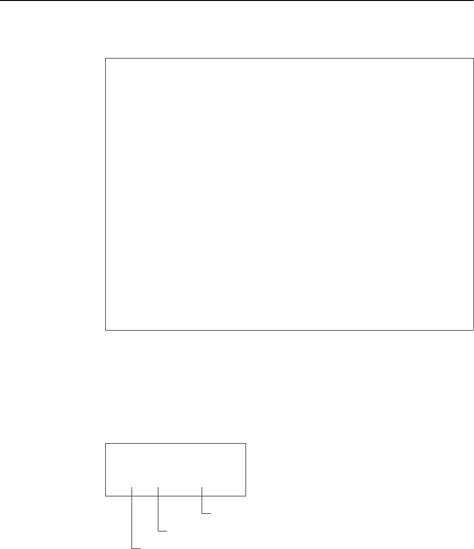
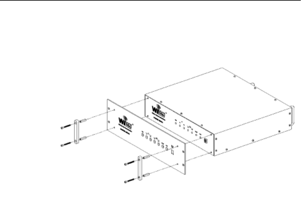
Installing the Units on a Rack
You can mount the 300-24 unit in a rack. The face plate and hardware for rack
installations is included in the 300-24 shipping package. Following is an illustration of
how to attach the face plate to the 300-24:
The unit is designed for installation in a 19 inch rack that is 3U high.
Version 1.1 - 01/04/00 31
Configuring Using the Menus
Overview
This section includes some general information about:
• accessing and modifying the configuration settings
• working with the configuration menus to define your 300-24 system settings
You can use the following methods to access and configure the 300-24 units:
•Telnet
• RS-232 Management Port
•SNMP
See Using SNMP on page 65 for information about using SNMP.
You can configure any unit as a base or a remote station. Each system configuration
includes only one base station, however it can include multiple remote stations. If you
need a true wide area network where all sites pass all data packets, the base and remote
stations need to communicate directly with each other. Every station will receive and
decode all packets and a true LAN/WAN network is created from individual segments.
Navigating the Configuration Menus
You use the keyboard keys to highlight and apply configuration options in the
configuration menus. See Conventions Used in this Guide on page 2 for descriptions of the
menu selection conventions used in this guide.
Accessing the Menus
As discussed earlier in this section, you can access the configuration menus using the
following two methods:
• RS-232 Management Port
•Telnet

Configuring Using the Menus
32 Version 1.1 - 01/04/00
Using the Console
You can access the configuration menus by connecting a PC to the unit through the
RS-232 Serial Port Interface. Typically, you will use this access method to complete
pre-installation configuration and to initially set up your 300-24 system.
To access the configuration menus through the console
1. Disconnect the power from the 300-24.
2. Connect a serial cable from a DB9 serial port on the PC to the RS-232 serial port on
the 300-24.
Note: You can access the RS-232 serial port through the RJ11 connection on the front
of the unit, or through the DB9 connection on the back panel. Adaptors to complete
these connections are shipped with the 300-24.
3. Start a terminal emulation program on the PC.
4. Set the terminal emulation program to emulate a VT100 terminal at:
• 9600 baud
• 8 data bits
• no parity
•1 stop bit
5. Set the terminal program to use the PC serial port that is connected to the 300-24 unit.
6. Power up the unit.
7. Press the spacebar on the keyboard.
The Login menu appears.
8. At the Enter Password prompt, type your User Password.
The Main System menu appears:
You can now start configuring the unit.
Main System Menu
-> System Revision Information
System Software ROM Images
System Current Status
System Security
System Commands
Network Configuration
Radio Configuration
Remote Station Configuration
MAC Layer Statistics
Remote Station
Configuration only
appears in the Main
System menu for
units configured as
the base station.

Navigating the Configuration Menus
Version 1.1 - 01/04/00 33
Using Telnet
Typically, you will use telnet to access the configuration menus once you have already
completed the initial unit configuration. Because you telnet to the unit’s IP address, you
must have already defined the address before you can telnet to it.
This configuration method is effective when you need to configure a unit from a remote
location.
To use the keyboard up and down arrow keys to navigate the configuration menus, ensure
that the VT100 Arrows feature in your telnet session is enabled.
To access the units through telnet
1. From a VT100 terminal, or emulation, type telnet <IP address>.
Where <IP address> is the address of the unit that you want to configure.
Note: If you are using Microsoft Telnet 1.0 as your terminal emulation application,
see To set the VT100 arrows in Microsoft Telnet below for instruction on setting the
VT100 arrows.
2. Press the Enter key.
The Login menu appears.
3. At the Enter Password prompt, type your User Password.
The Main System menu appears:
You can now start configuring the unit.
Main System Menu
-> System Revision Information
System Software ROM Images
System Current Status
System Security
System Commands
Network Configuration
Radio Configuration
IP Filter Configuration
MAC Layer Statistics
IP Filter
Configuration only
appears in the Main
System menu for
units configured as
remote stations.
Configuring Using the Menus
34 Version 1.1 - 01/04/00
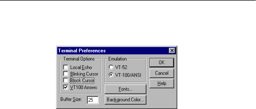
To set the VT100 arrows in Microsoft Telnet
1. In the active Microsoft Telnet 1.0 session, select Terminal, Preferences from the
menu bar.
The Terminal Preferences window appears:
2. Click to select the VT100 Arrows checkbox.
3. Click OK.
The VT100 arrows are enables in the telnet session, and you can use the keyboard
arrow keys to navigate the configuration menus.
Exiting the Configuration Menus
Once you have configured the unit, you must exit the menus before disconnecting the unit
from the PC.
To exit the configuration menus
1. Press the Esc key on the keyboard until you exit the configuration menus.
2. Power down the computer.

Viewing System Information
Version 1.1 - 01/04/00 35
Viewing System Information
You can use the Main System menu to view the following system information:
• system revision information
• system software ROM images
• current system status
• MAC (Media Access Control) layer statistics
Viewing System Revision Information
The system revision information shows details about the system including the:
• version of the 300-24 hardware
• RAM and ROM size
• version number of the system image file on the unit
• version date of the system image file on the unit
• name of the image file running on the 300-24
To view system revision information
1. From the Main System menu, select System Revision Information.
The System Revision Information window appears:
2. Following is a description of the fields in the window:
This field... Shows this...
Hardware The revision number of the 300-24 unit, and the RAM
and AMD Flash installed in the unit.
ROM Size The amount of read-only memory in the unit.
RAM Size The amount of random-access memory in the unit. This
value also appears in the Hardware field.
Software The revision number of the system image running on the
unit.
File Date The revision date and time of the system image running
on the unit.
File Name The file name of the system image running on the unit.
You can only view
information in this
window. You cannot
select or apply any
configuration
settings.
System Revision Information
Hardware Rev 0.0.0 (4MB RAM, 512K AMD Flash)
ROM Size 0x80000
RAM Size 0x400000
Software Rev 0.0.0 (Wi-LAN Ethernet/OFDM)
File Date Oct 8 1999 18:28:33
File Name FACTORY-IMAGE

Configuring Using the Menus
36 Version 1.1 - 01/04/00
Viewing System Software ROM Images
The System Software ROM Images window shows a list of all images that are available on
the unit. Initially, only the Factory-Image is available, however as new images are
developed, Wi-LAN will place them on their web site where you can download the system
image files.
To view system software ROM images
1. From the Main System menu, select System Software ROM Images.
The System Software ROM Images window appears:
2. Following is a description of the fields in the window:
This field... Shows this...
File Name The names of all system image files stored in the unit.
Revision The revision number of the system image file. Each time
the system image is modified, the revision number
increases by 1 unit. For example, the first revision to the
file would make the revision number 0.0.1.
Date The date the image file was last revised.
Time The time the image file was last revised.
Size The size of the image file in bytes.
Default Indicates if the image file starts when the 300-24 is
powered up.
Current Indicates if the image file is currently operating on the
unit.
You can only view
information in this
window. You cannot
select or apply any
configuration
settings.
System Software ROM Images
File Name Revision Date Time Size Default Current
-------------- -------- ----------- -------- ------ ------- -------
FACTORY-IMAGE 0.0.0 Oct 8 1999 18:28:33 124792 Yes Yes
Viewing System Information
Version 1.1 - 01/04/00 37
Viewing Current System Status
The Current System Status window shows historical and current information about the
unit. This information enables you to view the current state of the system and, if you are
troubleshooting system problems, provides historical information that can help you
monitor and troubleshoot your system.
To view current system status
1. From the Main System menu, select System Current Status.
The System Current Status window appears:
2. Following is a description of the fields in the window:
This field... Shows this...
Cumulative Run-Time The number of hours the system has been running
since purchase. This information is required for
maintenance purposes.
Current Run-Time The time duration that has passed since the unit was
last reset.
Power Cycles The number of times that the unit has been powered
down and repowered up.
Thermal Shutdowns The number of times that the unit has automatically
powered down due to overheating.
Successful Logins The number of times that the configuration menus
have been successfully accessed.
Unsuccessful Logins The number of times that access to the configuration
menus has failed.
You can only view
information in this
window. You cannot
select or apply any
configuration
settings.
System Current Status
Cumulative Run-Time 0 Days 3 Hours
Current Run-Time 0 Days 00:45:08
Power Cycles 5
Thermal Shutdowns 0
Successful Logins 6
Unsuccessful Logins 1
Local User Logged In User
Telnet User Logged In None
FTP User Logged In None
System Operational Status N/A
LAN Connection Status N/A
Thermal Status N/A
Correctable Error Rate N/A
Uncorrectable Error Rate N/A
Bit Error Rate N/A
Received Signal Strength RSSI N/A
Shows
historical
information.
Shows
current
information.
You can reset these
statistics to 0. See
Resetting the
Statistics on page 50
for more information.

Configuring Using the Menus
38 Version 1.1 - 01/04/00
Local User Logged In The access level of the user currently logged into
the configuration menus via the RS-232.
Telnet User Logged In The access level of the user currently logged into
the configuration menus via a telnet session.
FTP User Logged In The access level of the user currently logged into
the configuration menu via an FTP session.
System Operational Status Not implemented in this release.
LAN Connection Status Not implemented in this release.
Thermal Status Not implemented in this release.
Correctable Error Rate Not implemented in this release.
Uncorrectable Error Rate Not implemented in this release.
Bit Error Rate Not implemented in this release.
Received Signal Strength
RSSI Not implemented in this release.
This field... Shows this...

Viewing System Information
Version 1.1 - 01/04/00 39
Viewing the MAC Layer Statistics
The MAC layer statistics show the performance of the unit in the 300-24 system.
Information such as ethernet transmit and receive statistics, and OFDM encoder, decoder
and unpacking statistics enable you to view how the system is performing and where there
are errors that need to be addressed.
To view the MAC layer statistics
1. From the Main System menu, select MAC Layer Statistics.
The MAC Layer Statistics window appears:
2. Following is a description of the fields in the window:
This field... Shows this...
Total Frames Received The number of ethernet frames received from the
100Base-T connection.
Total Frames Transmitted The number of ethernet frames transmitted onto the
100Base-T connection.
Frames For Local Host
(Ethernet Receive) The number of ethernet frames received from the
100Base-T connection which were destined for the
300-24 unit’s TCP/IP stack.
You can only view
information in this
window. You cannot
select or apply any
configuration
settings.
MAC Layer Statistics
Ethernet Receive Statistics Ethernet Transmit Statistics
Total Frames Received 4 Total Frames Transmitted 0
Frames For Local Host 4 Frames From Local Host 0
Receive Errors 0 Frames Dropped 0
Frames Dropped 0
OFDM Decoder Statistics OFDM Encoder Statistics
Total Frames Decoded 0 Total Frames Encoded 4
Decoder IDMA Transfers 0 Encoder IDMA Transfers 4
Frames For Local Host 0 Frames From Local Host 0
Uncorrected Frames 0
Uncorrected Bytes 0 OFDM Unpacking Statistics
Corrected Frames 0
Corrected Bytes 0 Start Sequence Errors 0
Start Seq Extra Bytes 0
Header Errors 0
OFDM Channel Statistics
RSSI (dBm) -87 Average Throughput 640
Null Depth (dB) 0 Maximum Throughput 2016
Fade Margin (dB) 0
FEC BER 0
BER 0

Configuring Using the Menus
40 Version 1.1 - 01/04/00
Frames From Local Host
(Ethernet Transmit) The number of ethernet frames transmitted onto the
100Base-T connection which originated from the
300-24 unit’s TCP/IP stack.
Receive Errors The number of ethernet frames received with errors,
for example, runt (smaller than 64 bytes), jabber
(larger than 1518 bytes), or overflow error.
Frames Dropped
(Ethernet Transmit) The number of ethernet frames not transmitted due
to some error, for example, unable to transmit within
15 retries, or underflow error.
Frames Dropped
(Ethernet Receive) The number of ethernet frames dropped because
the wireless link is at capacity and all of the queues
are full.
Total Frames Decoded The number of ethernet frames that went through
the rs-decoder without uncorrectable errors.
Total Frames Encoded The number of ethernet frames that went through
the rs-encoder.
Decoder IDMA Transfers The number of RF superframes received by the
rs-decoder
Encoder IDMA Transfers The number of RF superframes produced by the
rs-encoder
Frames For Local Host
(OFDM Decoder) The number of ethernet frames that went through
the rs-decoder without uncorrectable errors which
were destined for the 300-24 unit’s TCP/IP stack.
Frames From Local Host
(OFDM Encoder) The number of ethernet frames that went through
the rs-encoder which originated from the 300-24
unit’s TCP/IP stack.
Uncorrected Frames The number of RF superframes received by the
rs-decoder that have uncorrectable errors.
Uncorrected Bytes The total number of bytes through the rs-decoder
which have uncorrectable errors.
Corrected Frames For Wi-LAN use only. The number of RF
superframes received by the rs-decoder that have
correctable errors.
Corrected Bytes For Wi-LAN use only. The total number of bytes
through the rs-decoder which have correctable
errors.
Start Sequence Errors For Wi-LAN use only.
Start Seq Extra Bytes For Wi-LAN use only.
Header Errors For Wi-LAN use only.
This field... Shows this...

Viewing System Information
Version 1.1 - 01/04/00 41
RSSI (dBm) Received signal strength indicator (in dB relative to
1 milliWatt).
Null Depth (dB) The difference between the strongest and weakest
carriers.
Fade Margin (dB) Fade Margin.
FEC BER Bit Error Rate after forward error correction.
BER Bit Error Rate before forward error correction.
Average Throughput The total throughput (per second) averaged over 10
seconds.
Maximum Throughput The highest throughput over 1 second since the last
stats reset.
This field... Shows this...
Configuring Using the Menus
42 Version 1.1 - 01/04/00
Setting the System Security
You can set the security levels and access settings for the system through the Main System
menu. These settings enable you to:
• set the ethernet and wireless access
• set community names which the SNMP Manager uses to access the unit
• define the user and supervisor passwords
• define the auto logout timeout
Setting Access Types
Setting the access types involves enabling or disabling access to the unit via the ethernet
and/or via the air. The default setting for access is set to on, for both the ethernet and
wireless. Depending on your security requirements, you may want to modify these
settings.
To set ethernet and wireless access
1. From the Main System menu, select System Security.
The System Security window appears:
2. Select System Ethernet Access.
An arrow appears to the left of the System Ethernet Access entry field.
3. In the System Ethernet Access entry field, select an option as follows:
Select... To...
On Enable access to the unit via the ethernet
Off Disable access to the unit via the ethernet.
System Security
System Ethernet Access -> on
System Wireless Access on
SNMP Public Community Name public
SNMP Private Community Name netman
Change User Password Press Enter to change password
Confirm User Password Press Enter to confirm password
Change Supervisor Password Press Enter to change password
Confirm Supervisor Password Press Enter to confirm password
Auto Logout Timeout (Minutes) 10
access type
settings
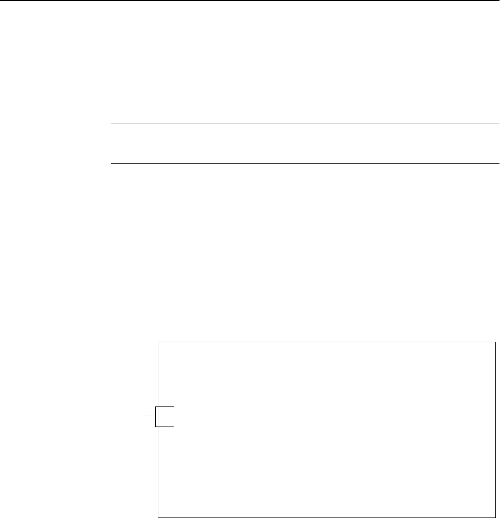
Setting the System Security
Version 1.1 - 01/04/00 43
4. Press the Enter key.
5. Select System Wireless Access.
An arrow appears to the left of the System Wireless Access entry field.
6. In the System Wireless Access entry field, select an option as follows:
7. Press the Enter key.
Setting Community Names
Setting a community name enables you to manage your system using an SNMP Manager.
The public and private community names identify the unit to the SNMP Manager and,
depending on the name SNMP uses to identify the unit, indicates if you can execute
commands on the unit.
To set a community name
1. From the Main System menu, select System Security.
The System Security window appears:
2. Select SNMP Public Community Name.
An arrow appears to the left of the SNMP Community Name entry field.
3. Press the Enter key.
The entry field changes to edit mode.
4. Type a name for the Community Name.
5. Press the Enter key.
The name appears in the entry field.
6. Select SNMP Private Community Name and then repeat steps 3 to 5.
Select... To...
On Enable access to the unit via the air
Off Disable access to the unit via the air.
System Security
System Ethernet Access on
System Wireless Access on
SNMP Public Community Name -> public
SNMP Private Community Name netman
Change User Password Press Enter to change password
Confirm User Password Press Enter to confirm password
Change Supervisor Password Press Enter to change password
Confirm Supervisor Password Press Enter to confirm password
Auto Logout Timeout (Minutes) 10
community
name
settings
A field in edit mode
appears in reverse
colors. The text
appears as white,
and the field is
highlighted in black.

Configuring Using the Menus
44 Version 1.1 - 01/04/00
Setting Passwords
You can control access to the configuration menus by setting passwords for users and
supervisors. Typically, users will have read-only access to all menus, while supervisors
can modify configuration settings.
To set passwords
1. From the Main System menu, select System Security.
The System Security window appears:
2. Select Change User Password.
An arrow appears to the left of the entry field.
3. Press the Enter key.
The entry field changes to edit mode.
4. Type the new password.
5. Press the Enter key.
An arrow moves to the left of the Confirm Password entry field.
6. Press the Enter key.
The entry field changes to edit mode.
7. Re-type the password you typed in step 4.
8. Press the Enter key.
The change is saved.
9. Select Change Supervisor Password and then repeat steps 3 to 8.
System Security
System Ethernet Access on
System Wireless Access on
SNMP Public Community Name public
SNMP Private Community Name netman
Change User Password -> Press Enter to change password
Confirm User Password Press Enter to confirm password
Change Supervisor Password Press Enter to change password
Confirm Supervisor Password Press Enter to confirm password
Auto Logout Timeout (Minutes) 10
password
settings
A field in edit mode
appears in reverse
colors. The text
appears as white,
and the field is
highlighted in black.

Setting the System Security
Version 1.1 - 01/04/00 45
Setting Automatic Timeouts
You can specify the maximum idle time period that can pass before the configuration
menus close and the Login menu reappears. This ensures that the system closes if a user
forgets to exit out of the configuration menus.
To set the automatic timeout period
1. From the Main System menu, select System Security.
The System Security window appears:
2. Select Auto Logout Timeout (Minutes).
An arrow appears to the left of the entry field.
3. Press the Enter key.
The entry field changes to edit mode.
4. Type the maximum idle time period, in minutes, that can pass before the configuration
menus close.
5. Press the Enter key.
The new value appears in the entry field.
If the menus
automatically time
out, the system
appears frozen.
Press the Enter key
to view the Login
window where you
can log in to the
menus.
timeout
settings
System Security
System Ethernet Access on
System Wireless Access on
SNMP Public Community Name public
SNMP Private Community Name netman
Change User Password Press Enter to change password
Confirm User Password Press Enter to confirm password
Change Supervisor Password Press Enter to change password
Confirm Supervisor Password Press Enter to confirm password
Auto Logout Timeout (Minutes) -> 10

Configuring Using the Menus
46 Version 1.1 - 01/04/00
Working with System Images
When you first power up the 300-24 unit, it starts with the factory-image. As new images
are developed, Wi-LAN will place them on their web site where you can download the
image files to the 300-24. Currently, only the factory-image is available. See Upgrading
Software via FTP on page 79 for more information about downloading new image files.
Setting the Default Image
As discussed above, as new images are developed and released, you will have the option
to select from a list of images to use on the 300-24. Once you have more than one image
saved on the unit, you can define which image file you want to use as the default each time
you power up the 300-24.
To set the default image
1. From the Main System menu, select System Commands.
The System Commands window appears:
2. Select Set Default System Image.
An arrow appears to the left of the entry field.
3. In the Set Default System Image entry field, scroll to select the image to use as the
default.
4. Press the Enter key.
The new image file appears in the field and will be used each time the 300-24 is
powered up.
System Commands
Set Default System Image -> FACTORY-IMAGE
Reboot Current Image Press Enter to Execute
Reboot a System Image FACTORY-IMAGE
Restore Factory Configuration Press Enter to Execute
Restore Poweron Configuration Press Enter to Execute
Enter Loopback Mode Press Enter to Execute
Return to Normal Mode Press Enter to Execute
Reset Radio Statistics Press Enter to Execute
Reset MAC Layer Statistics Press Enter to Execute
U
se
th
e arrow
k
eys
on the keyboard to
scroll through the
field selections.

Working with System Images
Version 1.1 - 01/04/00 47
Rebooting Images
You can reboot an image to reapply its settings to the unit. You can also choose to reboot
the 300-24 using a different image from that which you were originally using. If you make
changes to the network configuration, such as changing IP and MAC addresses, you must
reboot the current image for the changes to take effect. When you reboot the image, the
300-24 recopies the image from flash memory and runs it. See Configuring the Internet IP
Settings on page 52 for more information about changing the network configuration.
To reboot the current image
1. From the Main System menu, select System Commands.
The System Commands window appears:
2. Select Reboot Current Image.
An arrow appears to the left of the entry field.
3. Press the Enter key.
The 300-24 reboots using the current image.
To reboot a system image
1. From the Main System menu, select System Commands.
The System Commands window appears:
2. Select Reboot a System Image.
An arrow appears to the left of the entry field.
3. In the Reboot a System Image entry field, scroll to select the image you want to use.
4. Press the Enter key.
The 300-24 reboots using the selected system image.
System Commands
Set Default System Image FACTORY-IMAGE
Reboot Current Image -> Press Enter to Execute
Reboot a System Image FACTORY-IMAGE
Restore Factory Configuration Press Enter to Execute
Restore Poweron Configuration Press Enter to Execute
Enter Loopback Mode Press Enter to Execute
Return to Normal Mode Press Enter to Execute
Reset Radio Statistics Press Enter to Execute
Reset MAC Layer Statistics Press Enter to Execute
System Commands
Set Default System Image FACTORY-IMAGE
Reboot Current Image Press Enter to Execute
Reboot a System Image -> FACTORY-IMAGE
Restore Factory Configuration Press Enter to Execute
Restore Poweron Configuration Press Enter to Execute
Enter Loopback Mode Press Enter to Execute
Return to Normal Mode Press Enter to Execute
Reset Radio Statistics Press Enter to Execute
Reset MAC Layer Statistics Press Enter to Execute
If you try to enter
loopback mode
when you are
already in the mode,
failure appears in
the Enter Loopback
Mode field.

Configuring Using the Menus
48 Version 1.1 - 01/04/00
Restoring Configurations
When you make changes to the configuration settings, you can easily restore the default
configuration settings without having to reboot the 300-24. You have the option of
restoring the factory configuration settings, or you can restore the configuration settings
from the image you used when you last powered up the unit.
To restore the factory configuration
1. From the Main System menu, select System Commands.
The System Commands window appears:
2. Select Restore Factory Configuration.
An arrow appears to the left of the entry field.
3. Press the Enter key.
The factory configuration settings are restored.
To restore the poweron configuration
1. From the Main System menu, select System Commands.
The System Commands window appears:
2. Select Restore Poweron Configuration.
An arrow appears to the left of the entry field.
3. Press the Enter key.
The configuration settings that were applied when the unit was powered up are
restored.
System Commands
Set Default System Image FACTORY-IMAGE
Reboot Current Image Press Enter to Execute
Reboot a System Image FACTORY-IMAGE
Restore Factory Configuration -> Press Enter to Execute
Restore Poweron Configuration Press Enter to Execute
Enter Loopback Mode Press Enter to Execute
Return to Normal Mode Press Enter to Execute
Reset Radio Statistics Press Enter to Execute
Reset MAC Layer Statistics Press Enter to Execute

Working with Modes
Version 1.1 - 01/04/00 49
Working with Modes
You can change the mode settings on the 300-24 to loopback mode or normal mode. In
loopback mode, the 300-24 communicates with the baseband board. This mode enables
you to verify that the 300-24 is transmitting properly; you cannot receive or transmit in
this mode. In normal mode, the unit communicates with the RF Interface board and data is
transmitted and received to and from the air and wire.
To enter loopback mode
1. From the Main System menu, select System Commands.
The System Commands window appears:
2. Select Enter Loopback Mode.
An arrow appears to the left of the entry field.
3. Press the Enter key.
The 300-24 is now in loopback mode.
To enter normal mode
1. From the Main System menu, select System Commands.
The System Commands window appears:
2. Select Return to Normal Mode.
An arrow appears to the left of the entry field.
3. Press the Enter key.
The 300-24 is operating in normal mode.
System Commands
Set Default System Image FACTORY-IMAGE
Reboot Current Image Press Enter to Execute
Reboot a System Image FACTORY-IMAGE
Restore Factory Configuration Press Enter to Execute
Restore Poweron Configuration Press Enter to Execute
Enter Loopback Mode -> Press Enter to Execute
Return to Normal Mode Press Enter to Execute
Reset Radio Statistics Press Enter to Execute
Reset MAC Layer Statistics Press Enter to Execute
System Commands
Set Default System Image FACTORY-IMAGE
Reboot Current Image Press Enter to Execute
Reboot a System Image FACTORY-IMAGE
Restore Factory Configuration Press Enter to Execute
Restore Poweron Configuration Press Enter to Execute
Enter Loopback Mode Press Enter to Execute
Return to Normal Mode -> Press Enter to Execute
Reset Radio Statistics Press Enter to Execute
Reset MAC Layer Statistics Press Enter to Execute

Configuring Using the Menus
50 Version 1.1 - 01/04/00
Resetting the Statistics
The statistics that appear in the MAC Layer Statistics window and the System Current
Status window are cumulative that is, the values increase over time, until you reset the
numbers back to 0. Typically, you would reset the values when you want to track a
specific occurrence of an event. For example, a unit has had a thermal shutdown, and you
have corrected the cause of the shutdown (a heating/cooling problem). Once the problem
is corrected, you might want to reset the statistics. If the unit shuts down again, a 1 appears
in the statistic window and you can easily determine that a thermal shutdown has
reoccurred.
To reset the radio statistics
1. From the Main System menu, select System Commands.
The System Commands window appears:
2. Select Reset Radio Statistics.
An arrow appears to the left of the entry field.
3. Press the Enter key.
The values in the System Current Status window are reset to 0. See Viewing Current
System Status on page 37 to view the System Current Status window.
To reset the MAC Layer statistics
1. From the Main System menu, select System Commands.
The System Commands window appears:
2. Select Reset MAC Layer Statistics.
An arrow appears to the left of the entry field.
System Commands
Set Default System Image FACTORY-IMAGE
Reboot Current Image Press Enter to Execute
Reboot a System Image FACTORY-IMAGE
Restore Factory Configuration Press Enter to Execute
Restore Poweron Configuration Press Enter to Execute
Enter Loopback Mode Press Enter to Execute
Return to Normal Mode Press Enter to Execute
Reset Radio Statistics -> Press Enter to Execute
Reset MAC Layer Statistics Press Enter to Execute
System Commands
Set Default System Image FACTORY-IMAGE
Reboot Current Image Press Enter to Execute
Reboot a System Image FACTORY-IMAGE
Restore Factory Configuration Press Enter to Execute
Restore Poweron Configuration Press Enter to Execute
Enter Loopback Mode Press Enter to Execute
Return to Normal Mode Press Enter to Execute
Reset Radio Statistics Press Enter to Execute
Reset MAC Layer Statistics -> Press Enter to Execute


Configuring Using the Menus
52 Version 1.1 - 01/04/00
Configuring the Internet IP Settings
To enable the 300-24 unit to communicate with other units, you need to define the Internet
IP settings. You can also configure IP masks that you can use to create subnets for your
system. These subnets enable you to perform basic multicasting tasks.
Setting the Internet IP Address
You need to indicate the IP address for each 300-24 unit. This address enables
communication via TCP/IP.
To set the Internet IP address
1. From the Main System menu, select Network Configuration.
The Network Configuration window appears:
2. Select Internet IP Address.
An arrow appears to the left of the entry field.
3. Press the Enter key.
The entry field changes to edit mode.
4. Type the unique Internet IP address for the unit.
5. Press the Enter key.
The Internet IP address appears in the field and is assigned to the unit.
To set the Internet IP mask
1. From the Main System menu, select Network Configuration.
The Network Configuration window appears:
2. Select Internet IP Mask.
An arrow appears to the left of the entry field.
When you change
the IP or MAC
addresses, you must
reboot the current
image for the
changes to take
effect. See
Rebooting Images
on page 47 for more
information.
Network Configuration
Internet IP Address -> 192.168.3.85
Internet IP Mask 255.255.255.0
Ethernet MAC Address 000203040506
IP Routing Option Transparent
Default Gateway IP Address 192.168.3.52
SNMP NMS Trap IP Address 192.168.3.52
Network Configuration
Internet IP Address 192.168.3.85
Internet IP Mask -> 255.255.255.0
Ethernet MAC Address 000203040506
IP Routing Option Transparent
Default Gateway IP Address 192.168.3.52
SNMP NMS Trap IP Address 192.168.3.52

Configuring the Internet IP Settings
Version 1.1 - 01/04/00 53
3. Press the Enter key.
The entry field changes to edit mode.
4. Type the Internet IP Mask for the unit.
5. Press the Enter key.
The Internet IP Mask appears in the field and is assigned to the unit.
Setting the Ethernet MAC Address
Typically, you will never modify the ethernet MAC address. This address uniquely
identifies the 300-24 unit in the system. When you're connected to the internet from your
computer, a correspondence table relates your IP address to your computer's physical
(MAC) address on the LAN.
If you need to modify the address, you should contact Wi-LAN technical support to
discuss the required modifications. See Customer Support on page 3 for more information.
To set the ethernet MAC address
1. From the Main System menu, select Network Configuration.
The Network Configuration window appears:
2. Select Ethernet MAC Address.
An arrow appears to the left of the entry field.
3. Press the Enter key.
The entry field changes to edit mode.
4. Type the ethernet MAC address for the unit.
5. Press the Enter key.
The ethernet MAC address appears in the field and is assigned to the unit.
Network Configuration
Internet IP Address 192.168.3.85
Internet IP Mask 255.255.255.0
Ethernet MAC Address -> 000203040506
IP Routing Option Transparent
Default Gateway IP Address 192.168.3.52
SNMP NMS Trap IP Address 192.168.3.52

Configuring Using the Menus
54 Version 1.1 - 01/04/00
Setting the IP Routing Options
You can set your IP routing to enable all data to route through the unit, or you can set the
routing to IP Filtering, which will filter out certain IP ranges that you define in the IP
Filter Configuration window.
Note: For this release, only transparent mode is available.
To set the IP routing options
1. From the Main System menu, select Network Configuration.
The Network Configuration window appears:
2. Select IP Routing Option.
An arrow appears to the left of the entry field.
3. In the IP Routing Option entry field, scroll to select the option you want to apply:
4. Press the Enter key.
The selected option is applied.
Select... To...
Transparent Enable all received data to route through the
system.
IP Filtering Prevent data received from a specified range of IP
addresses from being routed through the system.
Network Configuration
Internet IP Address 192.168.3.85
Internet IP Mask 255.255.255.0
Ethernet MAC Address 000203040506
IP Routing Option -> Transparent
Default Gateway IP Address 192.168.3.52
SNMP NMS Trap IP Address 192.168.3.52

Configuring the Internet IP Settings
Version 1.1 - 01/04/00 55
Setting the Default Gateway IP Address
You need to define the IP address of the system gateway. This address designates the main
entry point into your network.
To set the default gateway IP address
1. From the Main System menu, select Network Configuration.
The Network Configuration window appears:
2. Select Default Gateway IP Address.
An arrow appears to the left of the entry field.
3. Press the Enter key.
The entry field changes to edit mode.
4. Type the default gateway IP address for the unit.
5. Press the Enter key.
The default gateway IP address is applied.
Setting the SNMP NMS Trap IP Address
The SNMP NMS Trap IP address identifies the IP address of the network manager. This
address basically communicates all alarms or events to the network manager. The network
manager can define the types of traps, or alarms, that will be forwarded to the IP address.
To set the SNMP NMS Trap IP address
1. From the Main System menu, select Network Configuration.
The Network Configuration window appears:
2. Select SNMP NMS Trap IP Address.
An arrow appears to the left of the entry field.
Network Configuration
Internet IP Address 192.168.3.85
Internet IP Mask 255.255.255.0
Ethernet MAC Address 000203040506
IP Routing Option Transparent
Default Gateway IP Address -> 192.168.3.52
SNMP NMS Trap IP Address 192.168.3.52
Network Configuration
Internet IP Address 192.168.3.85
Internet IP Mask 255.255.255.0
Ethernet MAC Address 000203040506
IP Routing Option Transparent
Default Gateway IP Address 192.168.3.52
SNMP NMS Trap IP Address -> 192.168.3.52

Configuring Using the Menus
56 Version 1.1 - 01/04/00
3. Press the Enter key.
The entry field changes to edit mode.
4. Type the SNMP NMS Trap IP address for the unit.
5. Press the Enter key.
The SNMP NMS Trap IP address appears in the entry field and is applied to the unit.
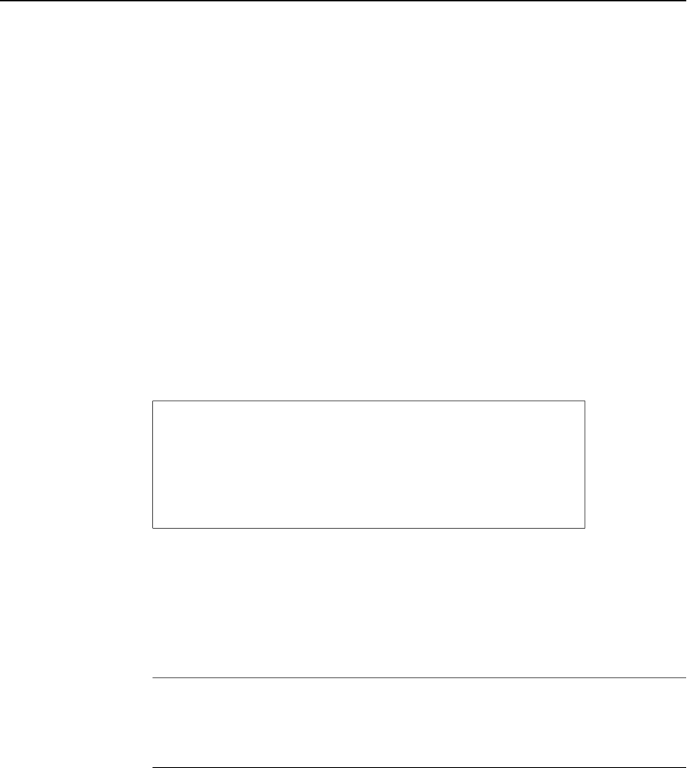
Configuring the Radio
Version 1.1 - 01/04/00 57
Configuring the Radio
You can configure the settings for the radio station type and the RF IDs and frequencies
using the Radio Configuration window. These settings can be defined for both remote and
base stations.
You can also configure settings that are specific to remote stations or to base stations.
These settings include:
• IP Filtering, which applies to only remote stations
• Polling Frequencies, which is configured and managed through the base station
Setting the OFDM Station Type
Before you install and start using the 300-24 in a system, you need to define the unit as a
base or a remote station.
To set the OFDM station type
1. From the Main System menu, select Radio Configuration.
2. Press the Enter key.
The Radio Configuration window appears:
3. Select OFDM Station Type.
An arrow appears to the left of the entry field.
4. Press the Enter key.
5. In the OFDM Station Type entry field, select a station type as follows:
6. Press the Enter key.
The unit is configured to the selected unit type.
To configure a... Do this...
Base Station In the OFDM Station Type entry field, scroll to select
Base Unit.
Remote Station In the OFDM Station Type entry field, scroll to select
Remote Unit.
Radio Configuration
OFDM Station Type -> Remote Unit
RF Station Id [0..1023] 2
RF Network Id [0..1023] 0
RF Center Frequency 2.440 GHz

Configuring Using the Menus
58 Version 1.1 - 01/04/00
Setting the RF IDs and Center Frequency
You need to identify the RF station and network IDs for the unit, and also set the RF
center frequency. All units in a given network should use the same frequency so they can
communicate with each other.
To set the RF Station ID
1. From the Main System menu, select Radio Configuration.
2. Press the Enter key.
The Radio Configuration window appears:
3. Select RF Station Id [0..1023].
4. Press the Enter key.
The entry field changes to edit mode.
5. Type a unique number for the RF Station ID.
6. Press the Enter key.
The unit is assigned the RF Station ID.
To set the RF Network ID
1. From the Main System menu, select Radio Configuration.
2. Press the Enter key.
The Radio Configuration window appears:
3. Select RF Network Id [0..1023].
4. Press the Enter key.
The entry field changes to edit mode.
5. Type a unique number for the RF Network ID.
6. Press the Enter key.
The unit is assigned the RF Network ID.
Radio Configuration
OFDM Station Type Remote Unit
RF Station Id [0..1023] -> 2
RF Network Id [0..1023] 0
RF Center Frequency 2.440 GHz
Every unit you
configure must have
a unique RF Station
ID. No two units can
have the same ID.
Radio Configuration
OFDM Station Type Remote Unit
RF Station Id [0..1023] 2
RF Network Id [0..1023] -> 0
RF Center Frequency 2.440 GHz

Configuring the Radio
Version 1.1 - 01/04/00 59
To set the RF center frequency
1. From the Main System menu, select Radio Configuration.
2. Press the Enter key.
The Radio Configuration menu appears:
3. Select RF Center Frequency.
4. Press the Enter key.
The entry field is highlighted.
5. Scroll to select the RF center frequency you will apply to all units in the network.
6. Press the Enter key.
The center frequency is applied to the unit.
Configuring the IP Filter for a Remote Station
You can create IP filters to filter the data that is transmitted and received through the
300-24 unit. The remote unit can filter packets received from the wire or air, or both.
When you define a filter, you indicate the host and mask IP addresses of the packets that
will be received and transmitted to the unit.
To configure the IP filter for a remote station
1. From the Main System menu, select IP Filter Configuration.
2. Press the Enter key.
The IP Filter Configuration window appears:
3. Select the Undefined field in the Filter row you are defining.
An arrow appears to the left of the field.
To ensure
communication
between units, all
units in the network
must have the same
center frequency.
Radio Configuration
OFDM Station Type Remote Unit
RF Station Id [0..1023] 2
RF Network Id [0..1023] 0
RF Center Frequency -> 2.440 GHz
You can configure IP
filters for only
remote stations.
IP Filter Configuration - Page 1
Filter Type Host/Net Address Host/Net Mask
1 ->Undefined 0.0.0.0 0.0.0.0
2 Undefined 0.0.0.0 0.0.0.0
3 Undefined 0.0.0.0 0.0.0.0
4 Undefined 0.0.0.0 0.0.0.0
5 Undefined 0.0.0.0 0.0.0.0
6 Undefined 0.0.0.0 0.0.0.0
7 Undefined 0.0.0.0 0.0.0.0
8 Undefined 0.0.0.0 0.0.0.0
9 Undefined 0.0.0.0 0.0.0.0
10 Undefined 0.0.0.0 0.0.0.0

Configuring Using the Menus
60 Version 1.1 - 01/04/00
4. Press the Enter key.
The entry field changes to edit mode.
5. Scroll to select the IP Filter type you are configuring. You can select from:
6. Press the Enter key.
The IP Filter Type is defined.
7. Press the right arrow key on the keyboard to move to the Host/Net Address field.
8. Press the Enter key.
The entry field changes to edit mode.
9. Type the IP Address of the Host/Net.
10. Press the Enter key.
The address is defined.
11. Press the right arrow key on the keyboard to move to the Host/Net Mask field.
12. Press the Enter key.
The entry field changes to edit mode.
13. Type the IP Address of the Host/Net Mask.
14. Press the Enter key.
You have configured the IP filter.
15. Repeat steps 3 to 14 to define additional IP filters.
Select this filter... To...
ENET - Wireless (RF) Filter the packets received from the wireline.
Wireless (RF) - ENET Filter the packets received from the air.
Undefined Not filter the packets.

Configuring the Radio
Version 1.1 - 01/04/00 61
Configuring the Polling List
You can configure the polling list for the base station. When you configure the list, you
must include the base station and all remote stations in the list.
To configure the polling list
1. From the Main System menu, select Remote Station Configuration.
The Remote Station Configuration menu appears:
2. In the Radio Id field, type the Radio Station ID for the station (you must identify a
unique Radio Id for all remotes and the base station).
Note: The order in which you enter the IDs determines the polling sequence of the
units.
3. In the Distance field, type the distance, in meters, from the Radio ID to the base
station.
Following is an example of a completed polling list entry:
Remote Station
Configuration only
appears in the Main
System menu for
units configured as
the base station.
Remote Station Configuration - Page 1
Remote Radio Id Distance Remote Radio Id Distance Remote Radio Id Distance
Number 0..1023 0..9999 Number 0..1023 0..9999 Number 0..1023 0..9999
1 ->1 1900 2 2 1900 3 0 0
4 0 0 5 0 0 6 0 0
7 0 0 8 0 0 9 0 0
10 0 0 11 0 0 12 0 0
13 0 0 14 0 0 15 0 0
16 0 0 17 0 0 18 0 0
19 0 0 20 0 0 21 0 0
22 0 0 23 0 0 24 0 0
25 0 0 26 0 0 27 0 0
28 0 0 29 0 0 30 0 0
31 0 0 32 0 0 33 0 0
34 0 0 35 0 0 36 0 0
37 0 0 38 0 0 39 0 0
40 0 0 41 0 0 42 0 0
43 0 0 44 0 0 45 0 0
46 0 0 47 0 0 48 0 0
49 0 0 50 0 0 51 0 0
52 0 0 53 0 0 54 0 0
55 0 0 56 0 0 57 0 0
Remote Radio Id Distance
Number 0..1023 0..9999
1 ->1 1900
The station is the first item in the polling list.
The RF Station ID is 1.
The RF Station ID 1 is 1900 meters from the base station.

Configuring Using the Menus
62 Version 1.1 - 01/04/00
4. Once you have entered the ID and distance for each remote station and the base
station, press the Esc key until you exit the Configuration menu.
5. Power down the computer.
You have configured the polling list.

Using the 300-24 Command Line
Version 1.1 - 01/04/00 63
Using the 300-24 Command Line
The 300-24 has a command line interface that you can use to perform basic commands.
The commands are a quick way to perform basic tasks while you remain logged into the
configuration menus.
Using the Basic Commands
While you are logged into the configuration menus, you can press the Esc key until you
exit out of the menus to the command line prompt. The command line prompt appears as:
wilan>
You can execute all of the 300-24 commands from this prompt.
Following are some of the commands you can execute at the prompt:
You can contact Wi-LAN customer support for additional information about the command
line interface. See Customer Support on page 3 for more information about contacting
Wi-LAN.
Type... To... Example...
help show the following command
summary list:
menu cls dir del ping
logout exit quit
wilan>help menu
menu return to the configuration menus wilan>menu
cls clear the terminal screen wilan>cls
dir show a file directory wilan>dir
exit log out of the command line
interface
or
terminate a remote telnet session
wilan>exit
logout log out of the command line
interface
or
terminate a remote telnet session
wilan>logout
quit log out of the command line
interface
or
terminate a remote telnet session
wilan>quit
ping ping a remote IP address wilan>ping 198.168.200.5
del delete a file wilan>del sample.txt

Configuring Using the Menus
64 Version 1.1 - 01/04/00

Version 1.1 - 01/04/00 65
Using SNMP
Using the Wi-LAN SNMP MIB
Included with each I.WiLL™ Access Point 300-24 unit (300-24), is a Simple Network
Management Protocol (SNMP) permitting configuration, monitoring, and control of:
• base stations via the ethernet
• remote units via the air
Units in remote and hard-to-reach locations can be easily configured, and network
managers can avoid or reduce downtime by monitoring network throughput, packet
collision rates, and interference.
SNMP is a protocol you can use to remotely manage a network element by polling, setting
terminal values, and monitoring network statistics and events. It is the de-facto internet
work management standard, designed to provide a mechanism for the exchange of
management information in a TCP/IP-based internet environment.
SNMP consists of the following three elements:
SNMP Element Description
Manager This element is installed on the network’s
host computer and is controlled by the
network administrator. From the host, the
Manager configures Agents, or polls Agents
for information.
Agent The Agent runs on each unit. An Agent
accepts configuration commands from the
Manager and collects network and terminal
information specified in the MIB.
Management Information Block (MIB) The MIB is a database which is accessed by
a specific set of commands that you can
execute using the SNMP Manager. There is
a standard MIB and a Wi-LAN customized
MIB that stores information relevant to the
operation of a wireless network.

Using SNMP
66 Version 1.1 - 01/04/00
Using the Wi-LAN MIB Object Identifier Nodes
All OID (Object Identifier) nodes in the private Wi-LAN MIB are numbered
1.3.6.1.4.1.2686.n where n is a private Wi-LAN MIB node number or branch of numbers.
This number is used in the nodes in the following pages.
All nodes containing statistical information are cleared on powerup and reset.
Values in all writeable nodes are stored in Flash memory and are retained until overwritten
by the administrator, even following power down or reset.

Using the Wi-LAN MIB Object Identifier Nodes
Version 1.1 - 01/04/00 67
Wi-LAN MIB Object Identifier Nodes
Following are descriptions of the nodes in the MIB for the 300-24:
Node # Address/Node Object Type Syntax Access Description
1.1.1 1.3.6.1.4.1.2686.1.1.1 defaultImage INTEGER R/W File descriptor id of Image to boot on hard
drive.
1.1.2 1.3.6.1.4.1.2686.1.1.2 ipAddr IpAddress R/W ENET/OFDM bridge IP address.
1.1.3 1.3.6.1.4.1.2686.1.1.3 ipMask IpAddress R/W ENET/OFDM bridge IP mask
1.1.4 1.3.6.1.4.1.2686.1.1.4 macAddr PhysAddress R/W ENET interface MAC address
1.1.5 1.3.6.1.4.1.2686.1.1.5 gatewayIpAddr IpAddress R/W Default Gateway IP address
1.1.6 1.3.6.1.4.1.2686.1.1.6 snmpNmsIpAddr IpAddress R/W SNMP NMS IP Address (Trap Destination)
1.1.7 1.3.6.1.4.1.2686.1.1.7 routingType INTEGER
(1, 3) R/W IP Routing Type: Bridge (1), Filter (3)
1.1.8 1.3.6.1.4.1.2686.1.1.8 stationType INTEGER
(1, 2) R/W OFDM Station Type: Base-Stn (1) or
Remote (2)
1.1.9 1.3.6.1.4.1.2686.1.1.9 radioId INTEGER
(0..1023) R/W RF Station Identifier
1.1.10 1.3.6.1.4.1.2686.1.1.10 networkId INTEGER
(0..1023) R/W RF Network Identifier
1.1.11 1.3.6.1.4.1.2686.1.1.11 centerFreq INTEGER R/W RF Center Frequency (2.410, 2.415, 2.430,
2.440, 2.450, 2.465, 2.470)
1.1.12-
1.1.21 1.3.6.1.4.1.2686.1.1.12 to
1.3.6.1.4.1.2686.1.1.21 vector1 to
vector 10 INTEGER
(0..65535) R/W RF Randomization Vector 1 to
RF Randomization Vector 10
1.1.22 1.3.6.1.4.1.2686.1.1.22 userPassword DisplayString
(Size 0..31) R/W System Login User-Level Password
1.1.23 1.3.6.1.4.1.2686.1.1.23 superPassword DisplayString
(Size 0..31) R/W System Login Supervisor-Level Password

Using SNMP
68 Version 1.1 - 01/04/00
1.1.24 1.3.6.1.4.1.2686.1.1.24 autoLogoutMins INTEGER R/W Input Inactivity Auto-Logout Timeout
(minutes)
1.1.25 1.3.6.1.4.1.2686.1.1.25 ethernetAccess INTEGER
(0, 1) R/W Enable/Disable Configuration Access Via
Ethernet: Disabled (0), Enabled (1)
1.1.26 1.3.6.1.4.1.2686.1.1.26 wirelessAccess INTEGER
(0, 1) R/W Enable/Disable Wireless Configuration
Access: Disabled (0), Enabled (1)
1.1.27 1.3.6.1.4.1.2686.1.1.27 publicName DisplayString
(Size 0..31) R/W SNMP Public Community Name
1.1.28 1.3.6.1.4.1.2686.1.1.28 privateName DisplayString
(Size 0..31) R/W SNMP Private Community Name
1.1.29 1.3.6.1.4.1.2686.1.1.29 ipFilterTable SEQUENCE of
IpFilterEntry NA The list of IP Filter Table entries.
1.1.29.1 1.3.6.1.4.1.2686.1.1.29.1 ipFilterEntry IpFilterEntry NA An IP Filter entry containing the IP address
and mask of the filter.
1.1.29.1.1 1.3.6.1.4.1.2686.1.1.29.1.1 ipFilterIndex INTEGER RO The 1-relative index of the filter in the table.
1.1.28.1.2 1.3.6.1.4.1.2686.1.1.28.1.2 ipFilterAddr IpAddress R/W The IP Filter net or host IP address.
1.1.28.1.3 1.3.6.1.4.1.2686.1.1.28.1.3 ipFilterMask IpAddress R/W The mask applied to the filter host or net
address. addr & mask = host or net number.
For hosts, the mask should be
255.255.255.255.
1.1.30 1.3.6.1.4.1.2686.1.1.30 remoteTable SEQUENCE
OF
RemoteEntry
NA The remote unit configuration table.
1.1.30.1 1.3.6.1.4.1.2686.1.1.30.1 remoteEntry RemoteEntry NA A Remote Unit Configuration Table entry.
1.1.30.1.1 1.3.6.1.4.1.2686.1.1.30.1.1 remoteIndex INTEGER RO The 1-relative index of a unit in the remote
configuration table.
1.1.30.1.2 1.3.6.1.4.1.2686.1.1.30.1.2 remoteRadioId INTEGER R/W The radio id for a unit in the remote
configuration table.
Node # Address/Node Object Type Syntax Access Description

Using the Wi-LAN MIB Object Identifier Nodes
Version 1.1 - 01/04/00 69
1.1.30.1.3 1.3.6.1.4.1.2686.1.1.30.1.3 remoteUnits INTEGER R/W The configuration units for a unit in the
remote configuration table.
1.2.1 1.3.6.1.4.1.2686.1.2.1 reboot INTEGER
reboot (1) R/W System Reboot Command
1.2.2 1.3.6.1.4.1.2686.1.2.2 restFactory INTEGER
restore (1) R/W Restore the Factory Configuration
Command
1.2.3 1.3.6.1.4.1.2686.1.2.2 restPoweron INTEGER
restore (1) R/W Restore the Poweron Configuration
1.3.1 1.3.6.1.4.1.2686.1.3.1 systemStatus INTEGER
down (0),
up (1)
RO Current System Status
1.3.2 1.3.6.1.4.1.2686.1.3.2 networkStatus INTEGER
off-line (0),
on-line (1)
RO Current LAN Connection Status
1.3.3 1.3.6.1.4.1.2686.1.3.3 thermalStatus INTEGER
warning (0),
normal (1)
RO Current System Thermal Status
1.3.4 1.3.6.1.4.1.2686.1.3.4 totalHours Counter RO Cumulative Run-Time Hours
1.3.5 1.3.6.1.4.1.2686.1.3.5 systemHours Counter RO Current Run-Time Hours Since Poweron
1.3.6 1.3.6.1.4.1.2686.1.3.6 powerCycles Counter RO Total Power Cycle Count
1.3.7 1.3.6.1.4.1.2686.1.3.7 thermalFails Counter RO Total Thermal Shutdown Count
1.3.8 1.3.6.1.4.1.2686.1.3.8 loginOkays Counter RO Number of Successful Logins
1.3.9 1.3.6.1.4.1.2686.1.3.9 loginFails Counter RO Number of Unsuccessful Login Attempts
1.3.10 1.3.6.1.4.1.2686.1.3.10 localUser INTEGER
loggedOut(0),
loggedIn(1)
RO Local User Login Status
Node # Address/Node Object Type Syntax Access Description

Using SNMP
70 Version 1.1 - 01/04/00
1.3.11 1.3.6.1.4.1.2686.1.3.11 telnetUser INTEGER
loggedOut(0),
loggedIn(1)
RO Telnet User Login Status
1.3.12 1.3.6.1.4.1.2686.1.3.12 ftpUser INTEGER
loggedOut(0),
loggedIn(1)
RO FTP User Login Status
1.3.13 1.3.6.1.4.1.2686.1.3.13 correctError INTEGER RO Correctable Error Rate
1.3.14 1.3.6.1.4.1.2686.1.3.14 uncorrectError INTEGER RO Uncorrectable Error Rate
1.3.15 1.3.6.1.4.1.2686.1.3.15 bitErrorRate INTEGER RO Bit Error Rate
1.3.16 1.3.6.1.4.1.2686.1.3.16 currentRssi INTEGER RO Current Received Signal Strength
1.4.1 1.3.6.1.4.1.2686.1.4.1 etherRxFrames Counter RO Ethernet Frames Received
1.4.2 1.3.6.1.4.1.2686.1.4.2 etherRxDropped Counter RO Ethernet Receive Frames Dropped
1.4.3 1.3.6.1.4.1.2686.1.4.3 etherRxErrors Counter RO Ethernet Receive Errors
1.4.4 1.3.6.1.4.1.2686.1.4.4 etherTxFrames Counter RO Ethernet Frames Transmitted
1.4.5 1.3.6.1.4.1.2686.1.4.5 etherTxDropped Counter RO Ethernet Transmit Frames Dropped
1.4.6 1.3.6.1.4.1.2686.1.4.6 idmaEncodeFrames Counter RO RS-Encoder IDMA Transfers
1.4.7 1.3.6.1.4.1.2686.1.4.7 idmaDecodeFrames Counter RO RS-Decoder IDMA Transfers
1.4.8 1.3.6.1.4.1.2686.1.4.8 rsEncSFrames Counter RO RS-Encoder Super Frames
1.4.9 1.3.6.1.4.1.2686.1.4.9 rsdecSFrames Counter RO RS-Decoder Super Frames
1.4.10 1.3.6.1.4.1.2686.1.4.10 rsDecSseqErrors Counter RO RS-Decoder Start Sequence Errors
1.4.11 1.3.6.1.4.1.2686.1.4.11 rsDecSseqXtra Counter RO RS-Decoder Start Sequence Extra Bytes
1.4.12 1.3.6.1.4.1.2686.1.4.12 rsDecUncFrames Counter RO RS-Decoder Uncorrectable Frames
1.4.13 1.3.6.1.4.1.2686.1.4.13 rsDecUncBytes Counter RO RS-Decoder Uncorrectable Bytes
1.4.14 1.3.6.1.4.1.2686.1.4.14 rsDecCorFrames Counter RO RS-Decoder Correctable Frames
Node # Address/Node Object Type Syntax Access Description

Using the Wi-LAN MIB Object Identifier Nodes
Version 1.1 - 01/04/00 71
1.4.15 1.3.6.1.4.1.2686.1.4.15 rsDecCorBytes Counter RO RS-Decoder Correctable Bytes
1.4.16 1.3.6.1.4.1.2686.1.4.16 upackSseqErrors Counter RO Unpacking Start Sequence Errors
1.4.17 1.3.6.1.4.1.2686.1.4.17 upackSseqXtra Counter RO Unpacking Start Sequence Extra Bytes
1.4.18 1.3.6.1.4.1.2686.1.4.18 upackHeadErrors Counter RO Unpacking Header Errors
1.4.19 1.3.6.1.4.1.2686.1.4.19 throughputMax INTEGER RO Maximum Throughput
1.4.20 1.3.6.1.4.1.2686.1.4.20 throughputAvg INTEGER RO Average Throughput
1.4.21 1.3.6.1.4.1.2686.1.4.21 stackTxEther Counter RO Ethernet Frames Transmitted by Local Host
1.4.22 1.3.6.1.4.1.2686.1.4.22 stackRxEther Counter RO Ethernet Frames Received for Local Host
1.4.23 1.3.6.1.4.1.2686.1.4.23 stackTxOfdm Counter RO OFDM Frames Transmitted by Local Host
1.4.24 1.3.6.1.4.1.2686.1.4.24 stackRxOfdm Counter RO OFDM Frames Received for Local Host
Node # Address/Node Object Type Syntax Access Description

Using SNMP
72 Version 1.1 - 01/04/00

Version 1.1 - 01/04/00 73
Appendix A: Product Specification
Overview
Following is the specification for the I.WiLL™ 300-24 Access Point (300-24). The
specification may change without notice. Contact Wi-LAN technical support to ensure
that you are working with the most recent specification. See Customer Support on page 3
for information about contacting Wi-LAN.
Specification
General Specifications
Modulation Method: Combined Direct Sequence Spread Spectrum
& Wide-band Orthogonal Frequency Division
Multiplexing (W-OFDM)
Wireless Data Rate: 30.0 Mbps
Wire Data Rate: 21 Mbps
RF Frequency Range: 2.4000 - 2.4835 GHz (unlicensed ISM band)
Number of Channels: 3 (center frequency can be set to any
frequency in RF range in 1 MHz increments)
Power Requirements: 110W @ 115VAC/230VAC 50/60 Hz
Physical Dimensions: 43.2 x 37.47 x 9.25 centimeters
(14 x 14.75 x 3.75 inches)
Approvals: Industry Canada, FCC, CE, CEPT
Product not available for sale until certification
has been obtained.

Appendix A: Product Specification
74 Version 1.1 - 01/04/00
Radio Specifications
Antenna Connector: "N" Male Connector
Mean OFDM Output Power: +15dBm nominal - see back of unit for
measured output power
Peak OFDM Power: 20dBm
Note: You must use the Peak OFDM Output
Power for link budget calculations.
Receiver Sensitivity: -78dBm nominal for quasi-error free (10-9
BER) operation - see back of unit for
measured Receiver Sensitivity
Network Support
Packet Format: IEEE 802.3 and Ethernet II
(High-level protocol transparent)
LAN Connections: 10BaseT and 100BaseTX
Bridge Functionality: Self-learning packet filtering by MAC address
(protocol independent)
Media Support: 10BaseT or 100BaseTX
Wireless Networking Protocols
Network Topologies: Point-to-Point, Point-to-Multipoint, Multipoint-
to-Multipoint
Repeater Mode: User Configurable
RF Collision Management: Polling, with Dynamic Time Allocation
Security
IP Filtering
Configuration, Management, and Diagnostics
Configuration Methods: SNMP, Telnet, RS-232 Management Port
SNMP: Version I, Standard and Enterprise MIBs
Management Port: Menu driven ASCII interface via RS-232, DB-9
connector
Management Port Functionality: Supports system configuration, security,
access control, wireless LAN diagnostics and
management

Version 1.1 - 01/04/00 75
Appendix B: Monitor and Test Links
Overview
You can monitor and test the 300-24 link once it is powered up, has an antenna attached to
it, and is receiving data. All link mode statistics appear in the MAC Layer Statistics
window. See Viewing the MAC Layer Statistics on page 39 for detailed information about
the window. You need to monitor the following three link mode statistics:
•Received Signal Strength Indicator (RSSI)
•Null Depth
•Fade Margin
Monitoring RSSI
The RSSI is the strength of the received signal in dBm (decibels referenced to a
milliWatt). When monitoring the RSSI, ensure that it meets the following statistical
criteria:
In a real application, a fade margin is required to allow for rain fading or other reception
anomalies. See Monitoring Fade Margin on page 76 for more information.
At the other extreme, the receive signal strength cannot be greater than -45dBm or the
receive LNA will saturate. If the RSSI is greater than -45dBm you must add sufficient
attenuation at the remote site to bring the RSSI down to an acceptable level.
Note: Check the back of the 300-24 unit for a label identifying that a RSSI Correction
Factor has been applied to the unit. If so, apply the following correction factor:
Actual_RSSI = RSSI - RSSI_Correction_Factor
RSSI Element Required Measurement
Noise Floor -95dBm
Signal to Noise Ratio 17dBm for quasi error free operation
Quasi Error Free 1 error in 109 bits after forward error
correction
RSSI Required for Quasi Error Free
Operation -95dBm + 17dBm = -78dBm
Receiver Sensitivity -78dBm

Appendix B: Monitor and Test Links
76 Version 1.1 - 01/04/00
Monitoring Null Depth
The Null Depth is the ratio in dB between the strongest OFDM carrier and the weakest
carrier. A Null Depth of greater than 0 dB indicates that there is no multipath reception.
Some multipath is usually present in your link, however adjustments to the position or
location of the receive antenna at the remote site can minimize the Null Depth. In some
cases, you cannot adjust the antenna position and location of the receive antenna at a
remote site.
Monitoring Fade Margin
The Fade Margin is the receive power in excess of the minimum required for error free
operation. See Monitoring RSSI on page 75 for information about receive power.
Fade Margin is computed for you using the following formula:
Thus, we have verified that the correct Fade Margin of 13dB is displayed.
Note: Check the back of the 300-24 unit for a label identifying that a Fade Margin
Correction Factor has been applied to the unit. If so, apply the following correction factor:
Actual Fade_Margin = Fade_Margin - Fade_Margin_Correction_Factor
Performing a Link Test
Linktest is a diagnostic tool for setting up and diagnosing links. Typically, you use linktest
when you:
•initially set up a remote
•diagnose a problem link
Linktest generates pseudo-random packets of information that are transmitted to the
station ID provided. The unit, or station ID, compares the pseudo-random data and
accumulates bit errors, RSSI, Fade Margin, and Forward Error Correction (FEC) statistics.
These statistics and regenerated pseudo-random data are sent in a packet back to the
originating unit. The originating unit then compares the pseudo-random data and at
approximately one second intervals, displays the accumulated statistics in the
configuration menus.
Before you start a linktest, you need the station ID of the base station. See Setting the RF
IDs and Center Frequency on page 58 for information about viewing station ID settings.
Formula Fade Margin = RSSI - Null Depth - Receiver Sensitivity
Example
Variables RSSI = -62dBm
Null Depth = 3dB
Receiver Sensitivity = -78dBm
Fade Margin = 13dB
Calculation Fade Margin = -62dBm - 3dB - -78dBm
Fade Margin = 13dB

Performing a Link Test
Version 1.1 - 01/04/00 77
To start a linktest
1. At the remote station from which you are performing the linktest, access the
configuration menus.
See Accessing the Menus on page 31 for more information about accessing the menus.
2. Press the Esc key until you enter the command line mode.
See Using the 300-24 Command Line on page 63 for more information about the
command line.
The following command line appears:
wilan>
3. At the command line prompt, type:
linktest <station id of the basestation>
4. Press the Enter key.
The following linktest results appear:
Following is a description of the information displayed in the linktest results screen:
This... Indicates...
R The statistics corresponding to the base station
receive.
Note: This applies if you are running linktest on
the remote to the base station.
L The statistics corresponding to the remote unit
receive.
Note: This applies if you are running linktest on
the remote to the base station.
RSSI The received signal strength indicator.
Fade Margin The fade margin is calculated as the number of dB
that the received signal strength exceeds the
minimum receiver sensitivity.
BER(x1E6) The bit error rate after forward error correction.
FEC Corrected The byte errors that were corrected by forward
error correction.
RSSI Fade Margin BER(x1E6) FEC corrected
RLRL RL RL
-52 -51 22 22 0 0 0 0
-52 -53 22 21 0 0 0 0
-52 -52 22 22 0 0 0 0
-52 -53 22 20 0 0 0 0
-52 -52 22 23 0 0 0 0
-53 -52 21 23 0 0 0 0
-52 -52 22 22 0 0 0 0
R = Remote to the unit running linktest.
L = Local to the unit running linktest.

Appendix B: Monitor and Test Links
78 Version 1.1 - 01/04/00
Note: If the link is bad and packets generated by the linktest are not received at
the other end, the following message appears:
No packets received
5. Press any key to exit linktest and return to the command line prompt.
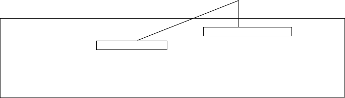
Version 1.1 - 01/04/00 79
Appendix C: Upgrading Software
Overview
You can upgrade the software on the 300-24 using one of the following methods:
•upgrading the new software via FTP
•installing the new software EEPROMS in the unit
This section provides instruction on how to upgrade your software via FTP; instructions
on how to install new software EEPROMS are including in the shipment of new
EEPROMS.
Upgrading Software via FTP
You can download all new software to your 300-24 unit through an FTP connection from
your computer. This procedure assumes that you have a copy of the updated software on
your computer. Contact Wi-LAN customer support for assistance downloading the
updated software from the Wi-LAN FTP server to your local computer. See Customer
Support on page 3 for information about contacting Wi-LAN support.
To upload software via FTP
1. Start a DOS session on your computer.
For information about starting a DOS session, refer to your Windows® online help.
2. At the c:\ prompt, type:
cd \projects\wib\current\bin
Note: The new software must be saved on your computer in the above directory.
3. Type ftp <IP address of the 300-24 unit>
Note: There is a space between ftp and the IP address. The following example uses
the IP address 192.168.3.85 for the 300-24 unit.
The DOS session window appears as:
c:\projects\wib\current\bin ftp 192.168.3.85
Connected to 192.168.3.85
220 Wi-LAN 300-24 OFDM Ethernet Bridge FTP Server
User (192.168.3.85(none)):
The IP address for your specific 300-24 unit will
appear here.
This procedure uses
the IP address
192.168.3.85 in all
steps. The IP
address you use
should be for your
specific 300-24 unit.

Appendix C: Upgrading Software
80 Version 1.1 - 01/04/00
4. At the User prompt, type ofdm.
5. Press the Enter key.
The password prompt appears.
6. At the Password prompt, type the supervisor password for the 300-24 unit.
Note: The password is configured in the configuration menus. See Setting Passwords
on page 44 for more information about setting the password and to view the default
password.
7. Press the Enter key.
The DOS session window appears as:
8. At the ftp prompt, type put ..\<filename>
where
<filename> represents the image file you are downloading.
Note: There is a space after you type put.
9. Press the Enter key.
The file starts downloading to the 300-24, and when the download is complete the
DOS session window appears as:
10. At the ftp> prompt, type bye.
The prompt returns to c:\projects\wib\current\bin>, and the ftp connection is closed.
C:\projects\wib\current\bin> ftp 192.168.3.85
Connected to 192.168.3.85
220 Wi-LAN 300-24 OFDM Ethernet Bridge FTP Server
User (192.168.3.85(none)):ofdm
331 Password required
Password:
230 Supervisor logged in
ftp>
C:\projects\wib\current\bin> ftp 192.168.3.85
Connected to 192.168.3.85
220 Wi-LAN 300-24 OFDM Ethernet Bridge FTP Server
User (192.168.3.85(none)):ofdm
331 Password required
Password:
230 Supervisor logged in
ftp>put ..\<filename>
200 Port set okay
150 Opening binary mode connection
226 Transfer complete
10484 bytes sent in 0.11 seconds (95.31 Kbytes/sec)
ftp>bye

Upgrading Software via FTP
Version 1.1 - 01/04/00 81
Using the Upgraded Software
Once you have uploaded the new software, you need to configure the unit to start using it.
To select the upgraded software
!Use the configuration menus to select the new software.
Follow the procedures in Setting the Default Image on page 46 to select the new
software.

Appendix C: Upgrading Software
82 Version 1.1 - 01/04/00
Version 1.1 - 01/04/00 83
Glossary
A
agent
In a SNMP context, the agent runs on each unit. An agent accepts configuration
commands from the manager and collects network and terminal information specified in
the MIB.
antenna
A device which takes electromagnetic energy from a circuit or wire and radiates it into
space rather than confining it.
antenna gain
Gain of the antenna over a dipole (dBd) or theoretical (dBi).
attenuation
Any loss in signal strength, due to resistance, absorption, capacitance, or any characteristic
of the medium or design of the system.
B
bandwidth
The span in hertz, that the information-bearing signal occupies or requires, or the
difference in hertz between the lowest and highest frequencies of a band.
baud
A measurement unit which defines the number of symbols per second (or signaling units
per second).
BER
Bit Error Rate. A percentage of bits per million, showing the number of bits in error
compared to the data bits actually sent.

Glossary
84 Version 1.1 - 01/04/00
C
cable loss
The signal loss experienced as it passes through the coax cable. Expressed in dB.
channel
The width of the spectrum band taken by a radio signal, usually measured in
kilohertz (kHz).
chip rate
Chip rate signifies the time occupied by that single frequency. Also the period of a code
clock, or the output of a code generator during one clock interval.
coaxial cable
A type of wire where the inner conductor is surrounded by an outer conductor. The outer
conductor serves as an electrical shield.
collision
The situation that exists when two users try to send a signal over the same medium at the
same time, and the signal uses the same frequencies.
CRC
Cyclic Redundancy Checksum Code. Based on mathematical theories, the CRC allows a
small number of checking bits to show whether the overall stream of bits has any errors in
it.
D
dB
Decibel. A relative measure of power used to specify power gains and losses. The
difference in power P1 and P2 expressed in dB is:
dBd
The gain or loss of an antenna referenced to a standard dipole.
Gain of a Standard Dipole = 2.14 dBi.
dBi
The gain or loss of an antenna referenced to an isotropic (theoretical point source)
radiator. This measure is used with only antennas, as it quantifies gain or loss of a physical
radiator with respect to a theoretical one.
dBm
A power measurement referenced to one milli-Watt. This is an absolute measure of power
rather than a relative measure such as a gain or a loss.
DB9
A D-shaped connector with 9 pins.
dB 10 P1
P2
-------
log
×
=

Version 1.1 - 01/04/00 85
E
EEPROM
Electrically Erasable Programmable Read-Only Memory. Non-volatile memory.
ERP
Effective Radiated Power. The power radiating from an antenna taking into account the
output power from the transmitter, connector losses, cable losses, and the antenna gain.
ETSI
European Telecommunications Standards Institute.
F
fade margin
The amount that the system gain plus the total antenna gain exceeds the path loss is called
the fade margin. The fade margin is calculated as the number of dB that the received
signal strength exceeds the minimum receiver sensitivity.
Fresnel Zone
The Fresnel Zone is the expansion of the RF signal radio angles in the vertical plane near
the middle of the RF path.
I
IEEE
Institute of Electrical and Electronics Engineers.
interference
Any signal that tends to hamper the normal reception of a desired signal.
ISM
Industrial, Scientific, and Medical. It is the license-exempt radio band in North America
and some European countries. It is also referred to as part 15.247 in the FCC regulation
that defines the parameters for use of the ISM band in the U.S., including power outputs,
spread-spectrum, and noninterference.
M
MAC Address
Media Access Controller Address. Alphanumeric characters that uniquely identify a
network-connected device.
Management Information Block
See MIB.
manager
When used in SNMP, this element is installed on the network’s host computer and is
controlled by the network administrator. From the host, the manager configures agents, or
polls agents for information.

Glossary
86 Version 1.1 - 01/04/00
MIB
Management Information Block. The MIB is a database which is accessed by a specific
set of commands that you can execute using the SNMP Manager. There is a standard MIB
and a Wi-LAN customized MIB that stores information relevant to the operation of a
wireless network.
O
OID nodes
Object Identifier Nodes. These are the individual nodes in a MIB. See SNMP and MIB.
P
path loss
The total loss from one end of the path to the other. This includes propagation losses, cable
losses, and any other losses that impact the system performance.
propagation loss
The signal loss experienced as it travels through the air. Expressed in dB.
R
RF
System of communication employing electromagnetic waves propagated through space.
Because of varying characteristics, radio waves of different lengths are employed for
different purposes and are usually identified by their frequency.
RS-232/422/423/485
Standards for serial communications, which define the voltages, currents, data rates, and
other factors about the signals to be used, as well as single-ended, differential, and
multi-drop operation.
S
sensitivity
The minimum signal strength required for usable performance. Expressed in dBm.
SNMP
Simple Network Management Protocol. A protocol you can use to remotely manage a
network element by polling, setting terminal values, and monitoring network statistics and
events. It is the de-facto internet work management standard, designed to provide a
mechanism for the exchange of management information in a TCP/IP-based Internet
environment.
spread spectrum
Any of a group of modulation formats in which a RF bandwidth much wider than
necessary is used to transmit an information signal so that a signal-to-noise improvement
may be gained in the process.

Version 1.1 - 01/04/00 87
system gain
The maximum path loss that the system can support for usable data transmission.
W
W-OFDM
Wide-band Orthogonal Frequency Division Multiplexing. A modulation scheme that
encodes data inside a radio frequency signal. OFDM sends a high-speed signal
concurrently on different frequencies. This allows for very efficient use of bandwidth and
provides for robust communications that can transmit through interferences, such as
occurring noise and stray and reflected signals, that can encumber radio communications.

Glossary
88 Version 1.1 - 01/04/00
Version 1.1 - 01/04/00 89
Index
Numerics
10/100 BaseT Ethernet connector 7
A
about this guide 1
access types
setting 42
accessing
configuration menus 31–34
adaptors
in shipping package 9
adjusting
antennas 29
agent 65
antenna gain 19
link budgets 18
requirements 19
antennas
attaching to mast 27
coaxial cable requirements 27
connector 7, 74
drip loops 27
fine-tuning 29
in shipping package 9
installation requirements 10
installing 27
outdoor 10
polarity requirements 27
pre-installation tasks 10
selecting 19
weatherproofing requirements 27
arrow keys
setting in telnet sessions 34
audience
guide 1
automatic timeouts
logging in after 45
setting 45
B
back panel 5, 7
connectors 7
base stations
configuring 57
pre-configuring 12
RF station ID 13
basic command line 63
Bit Error Rate (BER)
linktest displays 77
measuring 25
bridge functionality 74
C
cable loss
calculating 21
link budgets 18
ratings 21
cables
calculating loss 21
in shipping package 9
requirements 11
using surge suppressors 11
calculating
cable loss 21
effective radiated power 19
Fresnel radius 21
link budgets 17
path loss 22
propagation loss 20
system gain 18
center frequencies
configuring 58, 59
channels
number of 73
coaxial cables
for antennas 27

Index
90 Version 1.1 - 01/04/00
collision management
RF 74
colors
of LEDs 6
command line
basic commands 63
community names
setting 43
configuration menus
accessing 31
accessing through a console 32
accessing via telnet 33
exiting 34
logging into 33
navigating 31
using arrow keys 34
configuration settings
restoring 48
restoring factory configuration 48
restoring poweron settings 48
configuring
center frequencies 58
default gateway IP address 55
ethernet MAC address 53
internet IP address 52
internet IP mask 52
IP filters for remote stations 59
IP routing options 54
IP settings 52–56
methods 31
OFDM station type 57
polling lists 61
radios 57–62
RF IDs 58
RF network IDs 58
SNMP NMS trap IP address 55
stations before installation 11
connecting
300-24 to LAN 29
for installations 29
to LAN 74
connectors
10/100 BaseT Ethernet 7
antenna 7, 74
back panel 7
DB9 serial port 7
front panel 5
serial port 5, 7
conventions in this guide 2
copyright notice v
customer support
e-mail messages 3
for missing items 10
in North America 3
outside of North America 3
phone numbers 3
D
data encryption 74
data rates
wire 73
wireless 73
dB dBd 17
dBi 17
dBm 17
terms used 17
DB9 serial port connector 7
default
IP gateway address 55
passwords 12
system image file 46
definitions
antenna gain 18
cable loss 18
dBd 17
dBi 17
dBm 17
ERP 18
null depth 76
path loss 18
propagation loss 18
sensitivity 18
system gain 18
distances
between sites 10
setting in menus 15
drip loops
antennas 27
E
effective radiated power 18
calculating 19
formula 19
e-mail messages
customer support 3
ethernet access
setting 42
ethernet MAC address
setting 53

Index
Version 1.1 - 01/04/00 91
events
tracking 50
exiting
linktests 78
menus 34
F
face plate
for rack installations 30
factory configuration
restoring 48
fade margins 11, 22
linktests 77
monitoring 76
FEC
linktest displays 77
fields
MAC Layer Statistics window 39
System Current Status window 37
System Revision Information window 35
System Software ROM Images window 36
fine-tuning
antennas 29
format
packet 74
formulas
effective radiated power 19
Fresnel radius 21
path loss 22
propagation loss 20
system gain 18
frequency range
RF 73
Fresnel radius
calculations 21
formulas 21
Fresnel zone 20
front panel 5
connectors 5
illustration 5
LEDs 6
FTPusing to upgrade software 79
functionality
bridge 74
management port 74
G
getting help 3
grounding 10
using the ground screw 8
guide
audience 1
conventions 2
copyright notices v
user notices v
H
hardware
verifying revision numbers 27
viewing version 35
I
image files
rebooting 47
setting 46
installation
requirements 9
shipping package contents 9
installing
AC Power Level Switch 27
antennas 27
base stations 27–29
completing connections 29
on a rack 30
powering up units 27
rack size 30
remote stations 27–29
verifying hardware revision numbers 28
verifying RF port 28
verifying software revision numbers 28
intended audience 1
internet IP mask
setting 52
IP address
setting 52
IP filters
configuring for remote stations 59
IP mask
setting 52
IP routing option
setting 54
IP settings
configuring 52–56
default gateway IP address 55
ethernet MAC address 53

Index
92 Version 1.1 - 01/04/00
IP settings (cont)
internet IP mask 52
IP routing options 54
SNMP NMS trap IP address 55
ISM band 1
L
LAN connections 74
from 300-24 29
LEDs
colors 6
on front panel 6
status 6
types 6
lightening arrestors 10
link budgets
antenna gain 18
cable loss 18
calculating 17
effective radiated power 18
path loss 18
propagation loss 18
sensitivity 18
system gain 18
variables 18
verifying 24
link mode
monitoring 75–76
link statistics
measuring 24
linktests 76
BER 77
exiting 78
fade margins 77
FEC 77
performing 76–78
performing on remotes 76
RSSI 77
locations
of units in site 10
logging in
after automatic timeout 45
to menus 33
loopback mode
entering 49
M
MAC layer statistics
resetting 50
viewing 39
window fields 39
management port functionality 74
measuring
bit error rate 25
link statistics 24
media support 74
menus
accessing through a console 32
exiting 34
logging into 33
MIB 65
Wi-LAN OID nodes 67–71
missing items
contacting customer support 10
modes
entering loopback mode 49
entering normal mode 49
repeater 74
modulation method 73
monitoring
fade margin 76
link mode 75–76
null depth 76
RSSI 75
N
names
system image files 35
navigating
configuration menus 31
network topologies 74
nodes
OID 66
noise floor 75
normal mode
entering 49
notices
copyright v
user v
null depth
definition 76
monitoring 76

Index
Version 1.1 - 01/04/00 93
O
OFDM station
selecting type 12
OID nodes 66
outdoor antennas 10
output power 74
overview
completing pre-installation 9
configuring the menus 31
get started 5
installing base and remote stations 27
monitor link mode 75
of sections 1
product 1
production specification 74
setting the RF link 17
upgrading software 79
P
packet format 74
panels
back 5, 7
connectors on back 7
connectors on front 5
front 5
LEDs on front 6
passwords
default 12
setting supervisor passwords 44
setting user passwords 44
path loss
calculating 22
formula 22
link budgets 18
phone numbers
customer support 3
physical dimensions
of 300-24 73
rack size 30
polarity requirements
antennas 27
polling lists
configuring 61
pre-configuring 14
power
AC power switch 27
output 74
requirements 73
supply cord 9
poweron settings
restoring 48
pre-configuring
base stations 12
polling list 14
RF station ID 13
stations 11–15
pre-installation 9–15
cable requirements 11
fade margins 11
planning physical layout 10
prerequisites 9
radio path 10
weather requirements 11
preliminary site layout 10
product specification 73
propagation loss
calculating 20
formula 20
Fresnel zone 20
link budgets 18
Q
quasi error free 75
R
rack installations 30
rack size 30
radio paths
checking 10
checking before installation 10
radios
configuring 57–62
configuring polling lists 61
resetting statistics 50
setting OFDM station type 57
RAM
in 300-24 35
ratings
of cable loss 21
rebooting
system image files 47
receiver sensitivity 74
regulatory approvals 73
regulatory bodies
ETS 20
FCC 20
Industry Canada 20

Index
94 Version 1.1 - 01/04/00
remote stations
configuring 57
configuring IP filters 59
performing linktests 76
RF station ID 13
repeater mode 74
requirements
installation 9
power 73
RSSI 75
resetting
MAC layer statistics 50
radio statistics 50
statistics 50
restoring
factory configuration settings 48
poweron configuration settings 48
RF collision management 74
frequency range 73
links 17
RF IDs
configuring 58
configuring network ID 58
pre-configuring stations ID 13
RF ports
verifying 28
ROM
in 300-24 35
RS-232 Management Port Configuration 31
RSSI
linktest display 77
maximum dBm 75
monitoring 75
noise floor 75
quasi error free 75
receiver sensitivity 75
required for quasi error free operation 75
signal to noise ratio 75
statistical criteria 75
S
scrambling 74
security
access types 42
community names 43
setting automatic timeouts 45
setting passwords 44
system 42
selecting
antennas 19
OFDM station type 12
sensitivity
link budget variable 18
serial port connector 5, 7
setting
automatic timeouts 45
default gateway IP address 55
default system image file 46
distance between sites 10
ethernet access 42
internet IP address 52
internet IP mask 52
IP routing options 54
passwords 44
RF center frequencies 59
SNMP NMS trap IP address 55
SNMP private community name 43
SNMP public community names 43
supervisor passwords 44
user passwords 44
wireless access 42
shipping package contents 9
signal to noise ratio 75
sitesdetermining distance between 10
SNMP
agent 65
configuration 31
MIB 65
OID nodes 66
setting community names for 43
setting private community names 43
setting public community names 43
version 74
Wi-LAN MIB 65–71
SNMP NMS trap IP address
setting 55
software
uploading via FTP 79
verifying revision numbers 27
specifications
product 73
stations
pre-configuring 11
setting distance between 15

Index
Version 1.1 - 01/04/00 95
statistics
MAC layer statistics 50
radio statistics 50
resetting 50
status
LEDs 6
supervisors
setting passwords 44
surge suppressors
at cable entry 11
System Current Status window
fields 37
system gain
calculation 18
formula 18
how to use 18
variables 18
system image files
names 35
rebooting 47
setting the default 46
versions 35
working with 46–47
system information
MAC layer statistics 39
system software ROM images 36
viewing 35
viewing current system status 37
viewing system revision 35
System Revision Information window
fields 35
system security 42
System Software ROM Images window
fields 36
T
telnet
accessing configuration menus 33
configuration 31
setting arrow keys in sessions 34
tracking
events 50
troubleshooting 3
U
units
locations in site 10
upgraded software
using 81
upgrading software 79–81
via FTP 79
users
notices v
setting passwords 44
V
variables
link budgets 18
system gain 18
verifying
hardware revision numbers 27
link budgets 24
RF ports 28
software revision numbers 27
versions
hardware 35
system image files 35
viewing
current system status 37
system revision information 35
system software ROM images 36
W
weatherproofing
antennas 27
requirements 11
wire data rate 73
wireless access
setting 42
wireless data rate 73