Wi Lan EB01 Wireless Ethernet Bridge User Manual Hopper 120 24
Wi Lan Inc Wireless Ethernet Bridge Hopper 120 24
UserManual.wiki
>
Wi Lan
>
EB01 User Manual
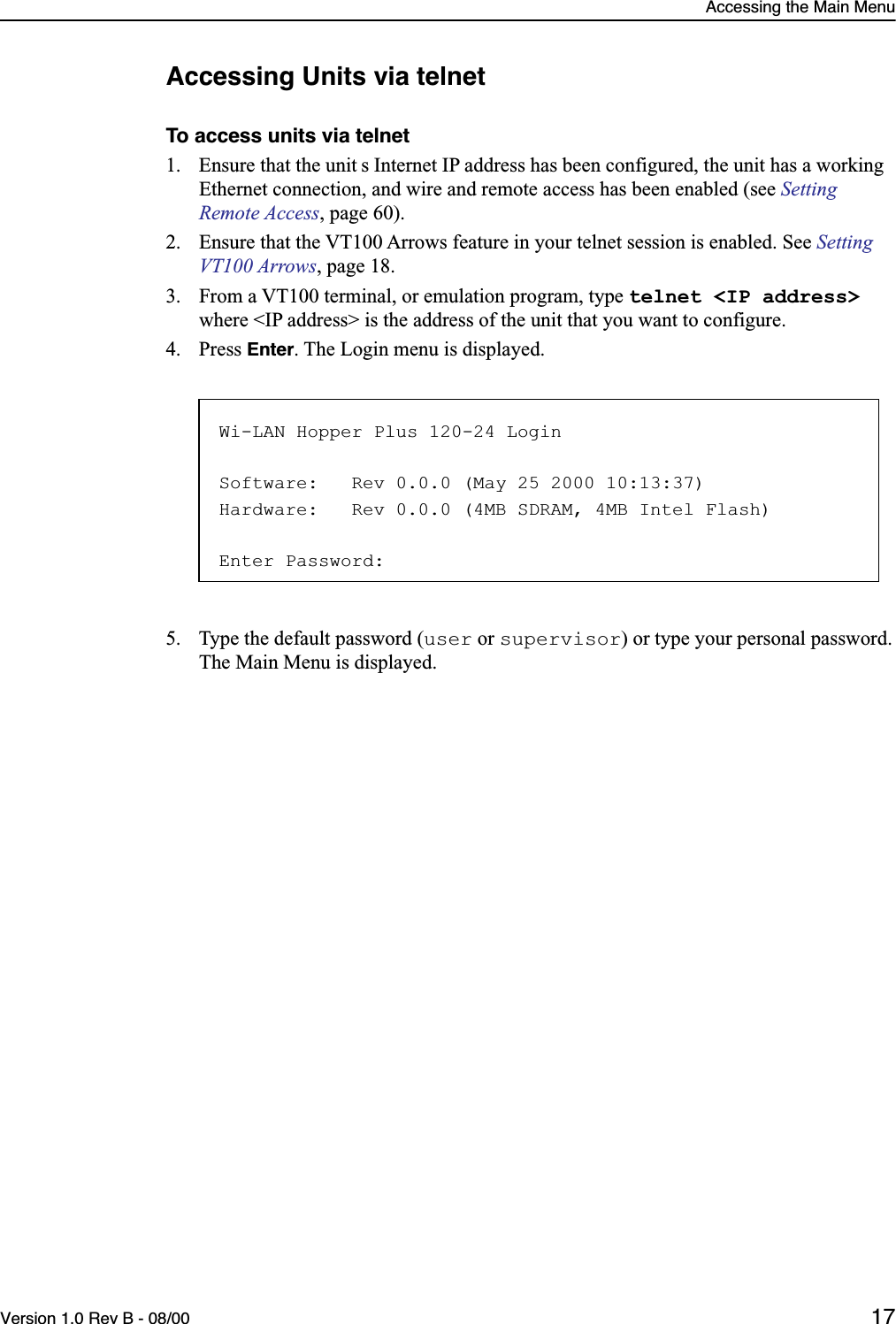
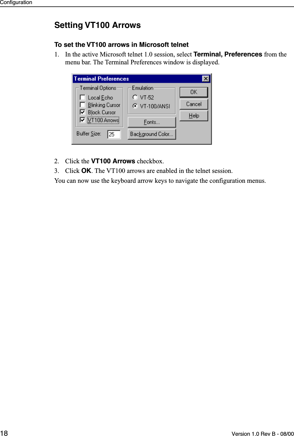
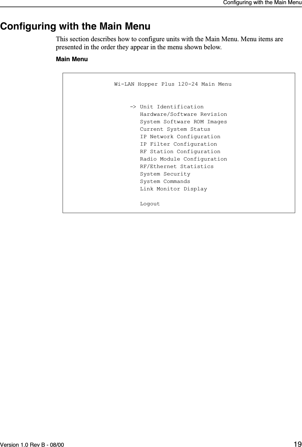
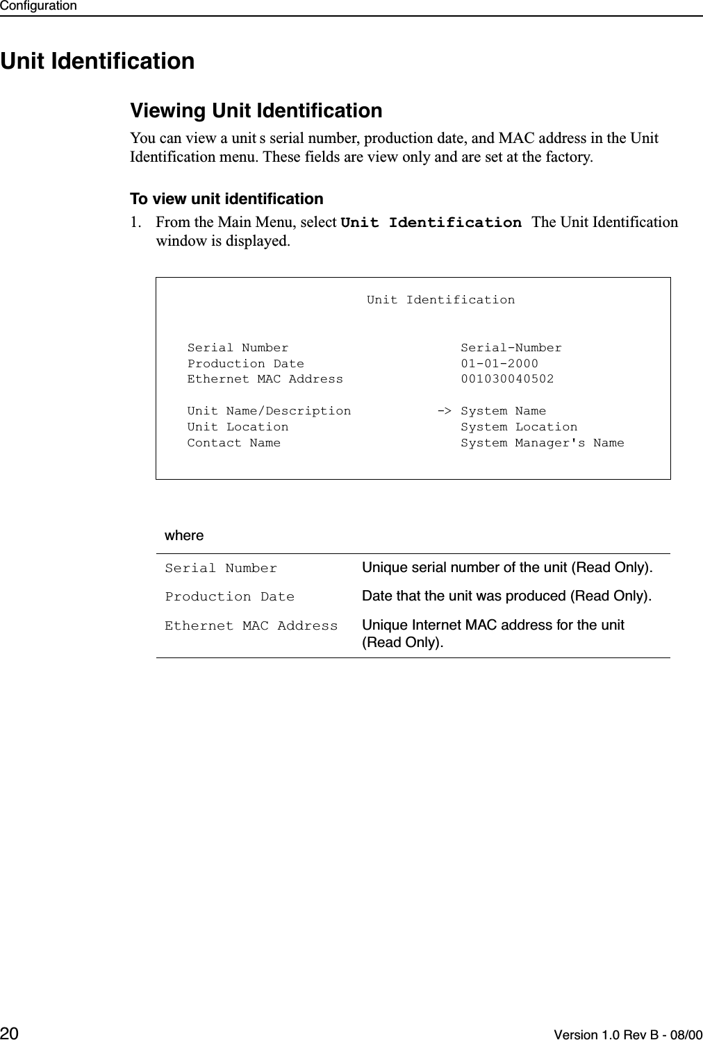
Users Manual with RF safety statement
Navigation menu
Upload a User Manual
Namespaces
Wiki Guide
HTML
PDF
Info
Views
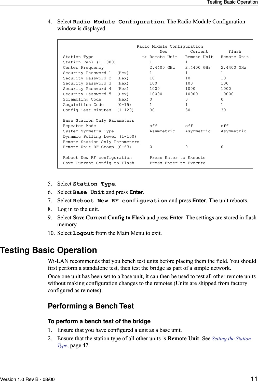
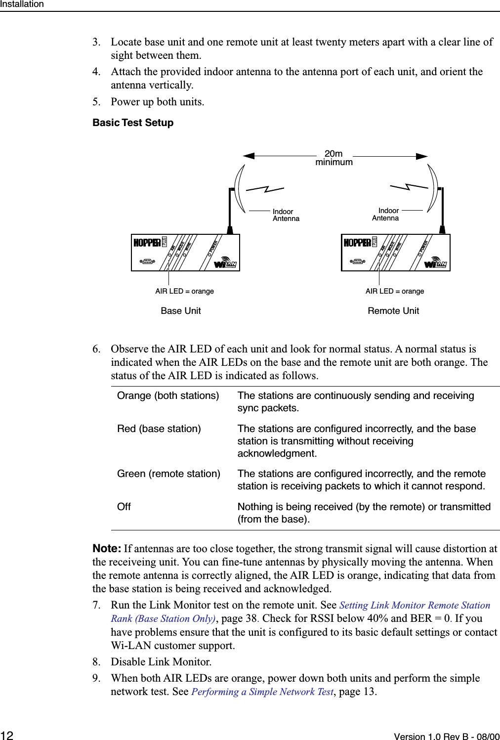
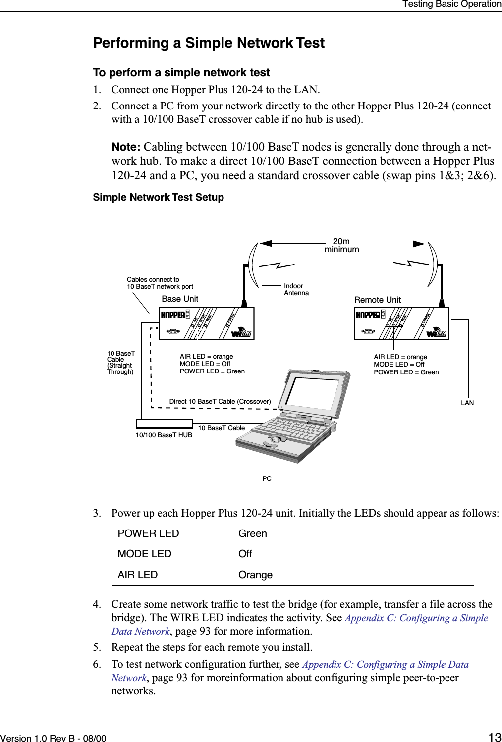
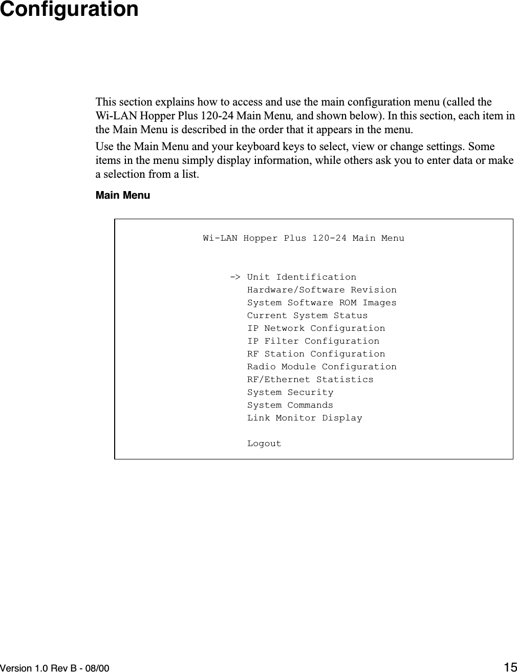
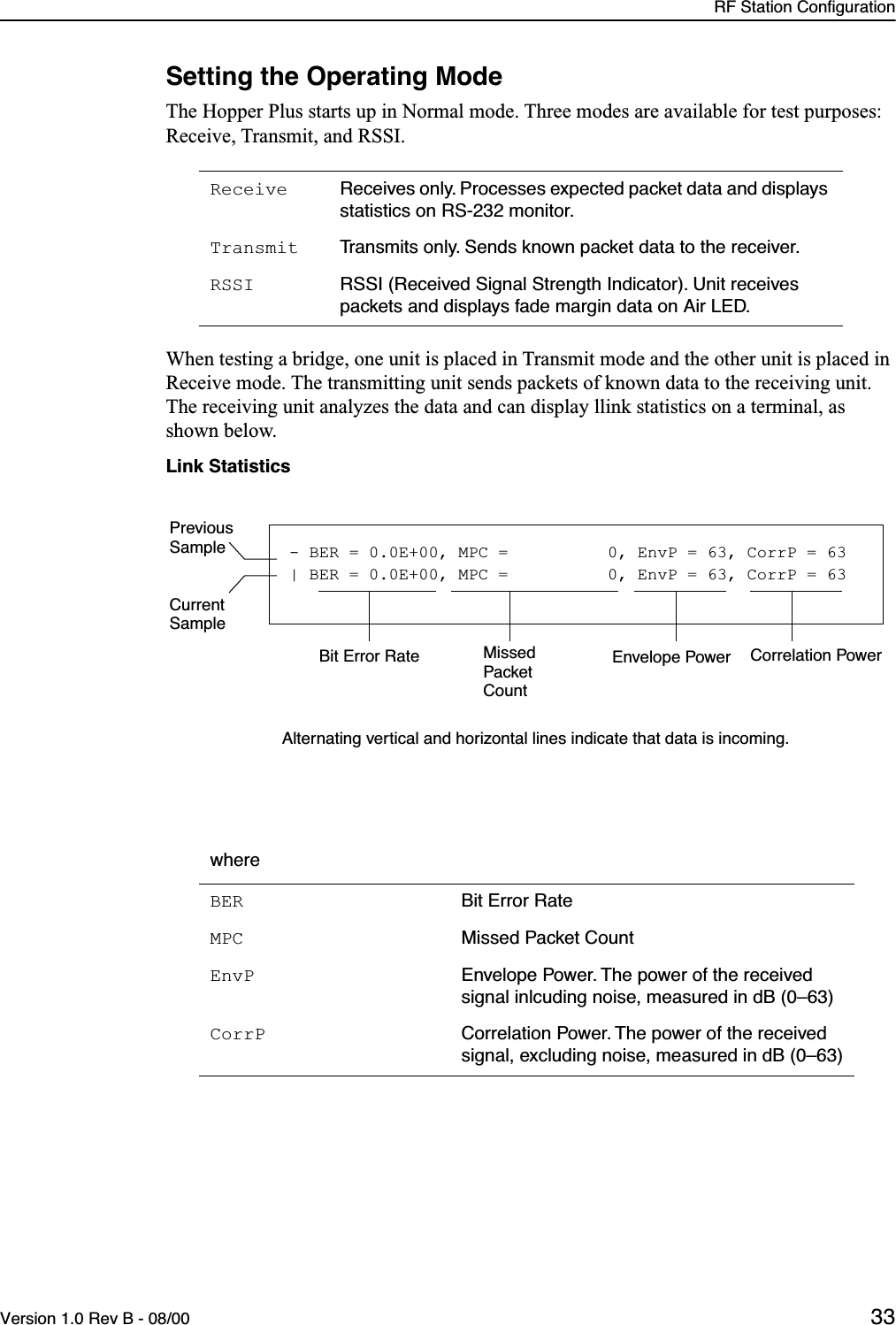
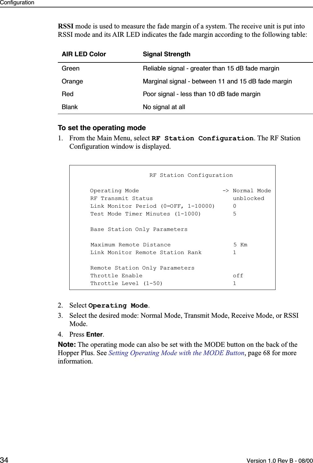
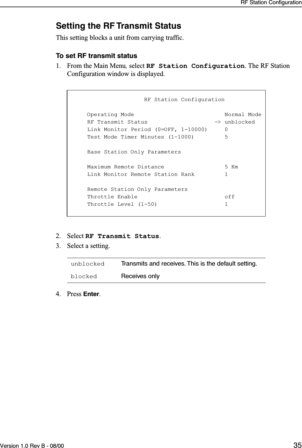
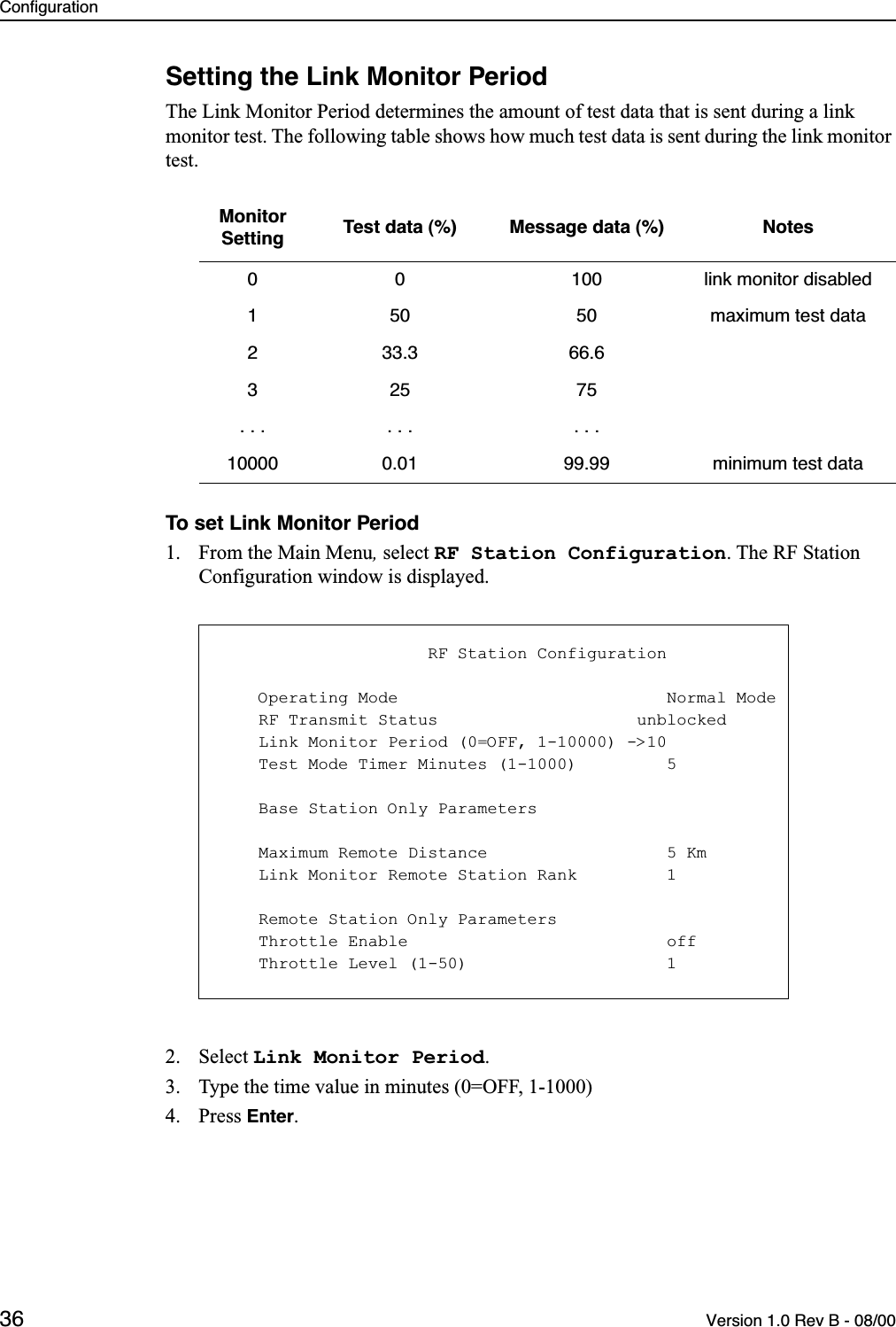
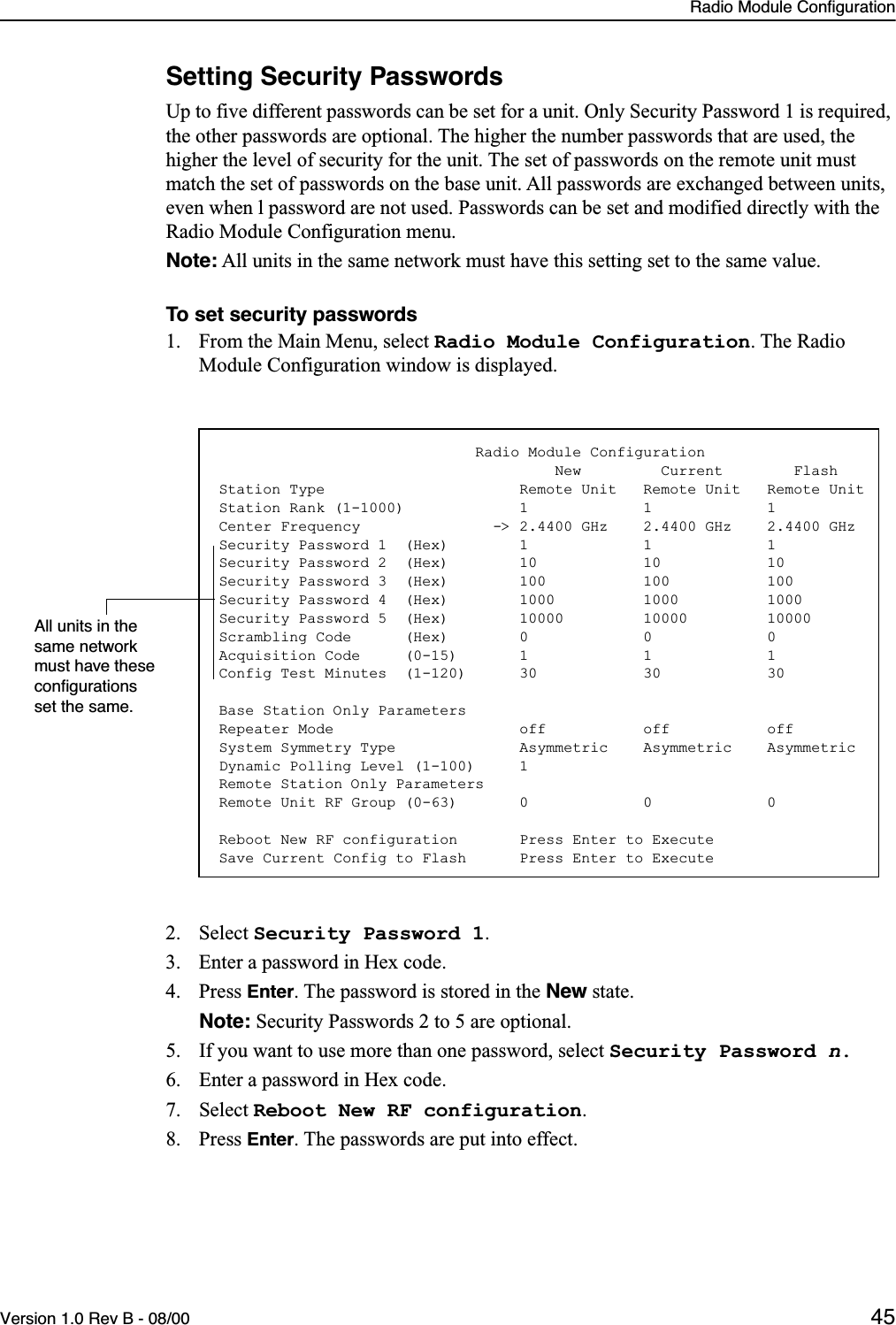
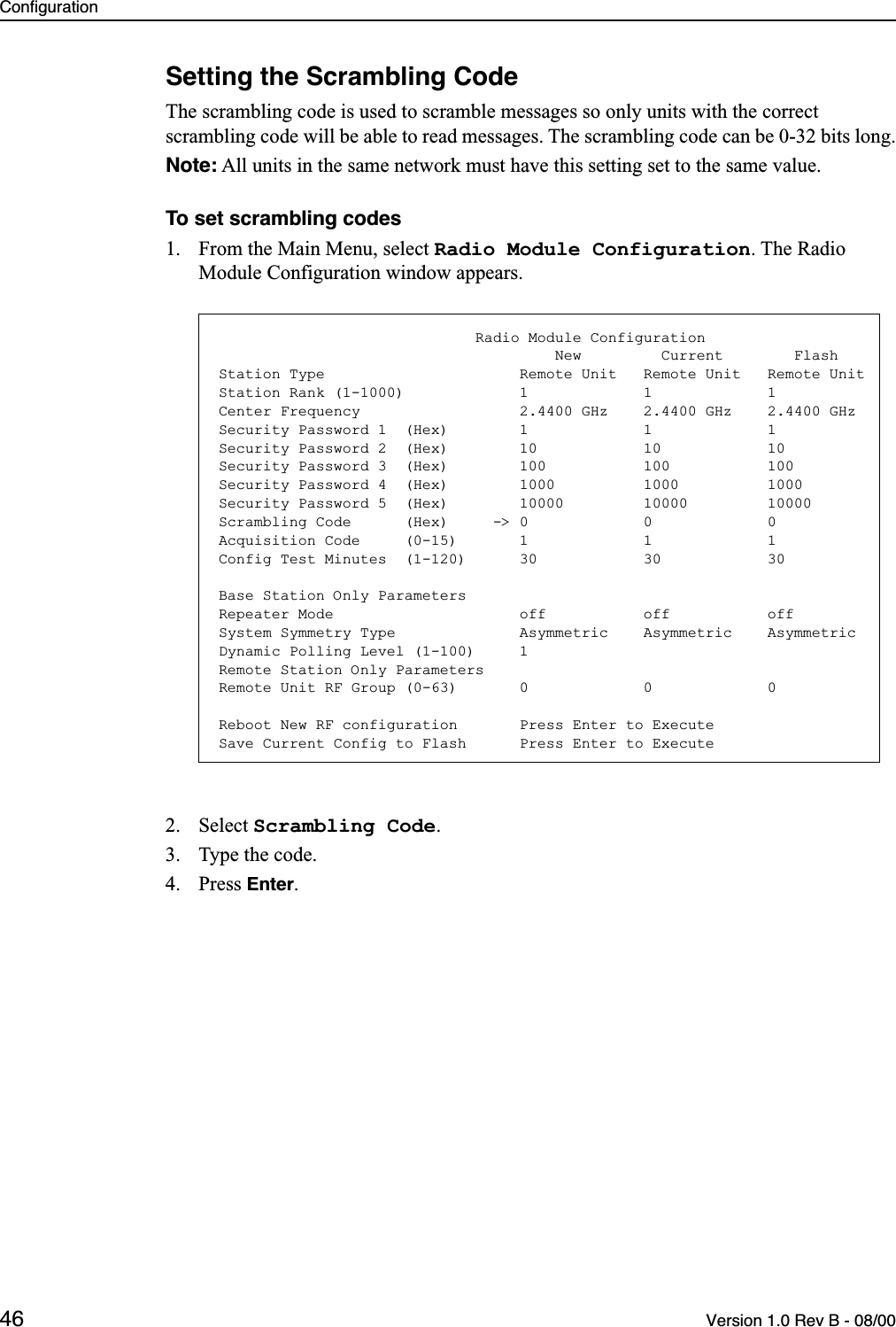
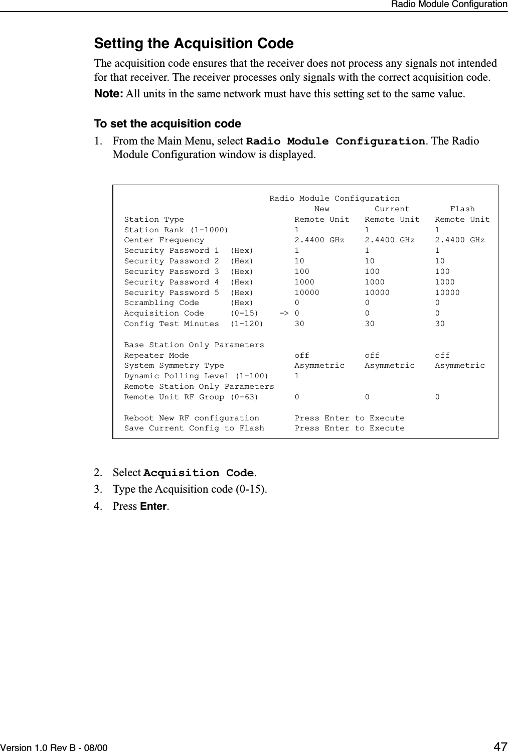
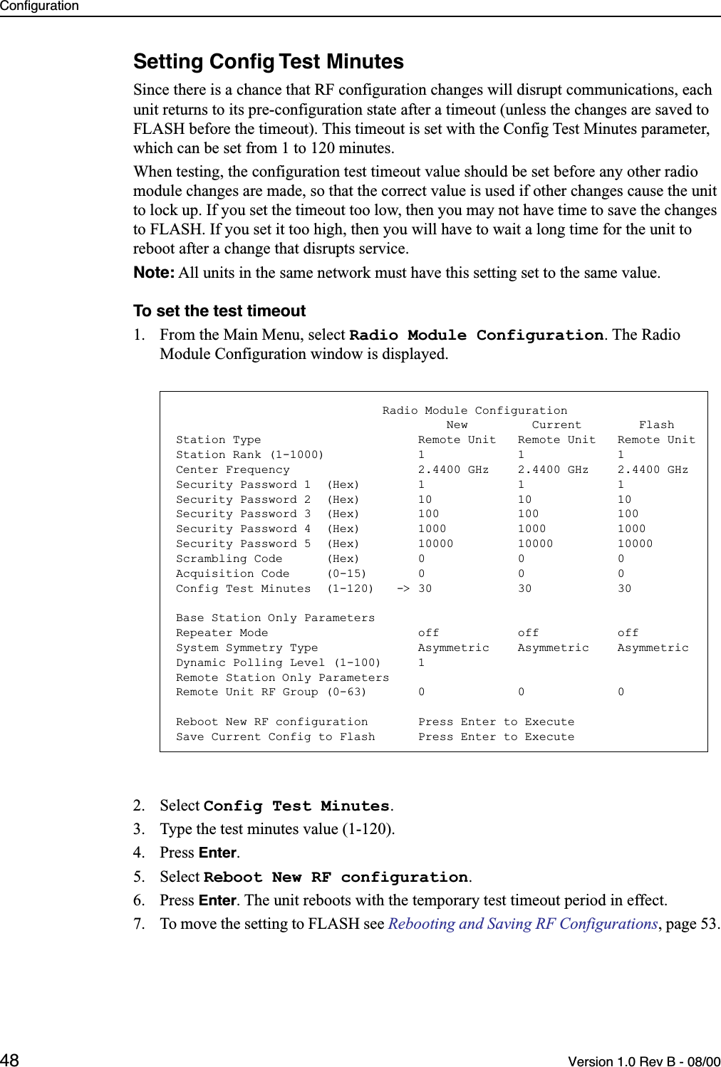
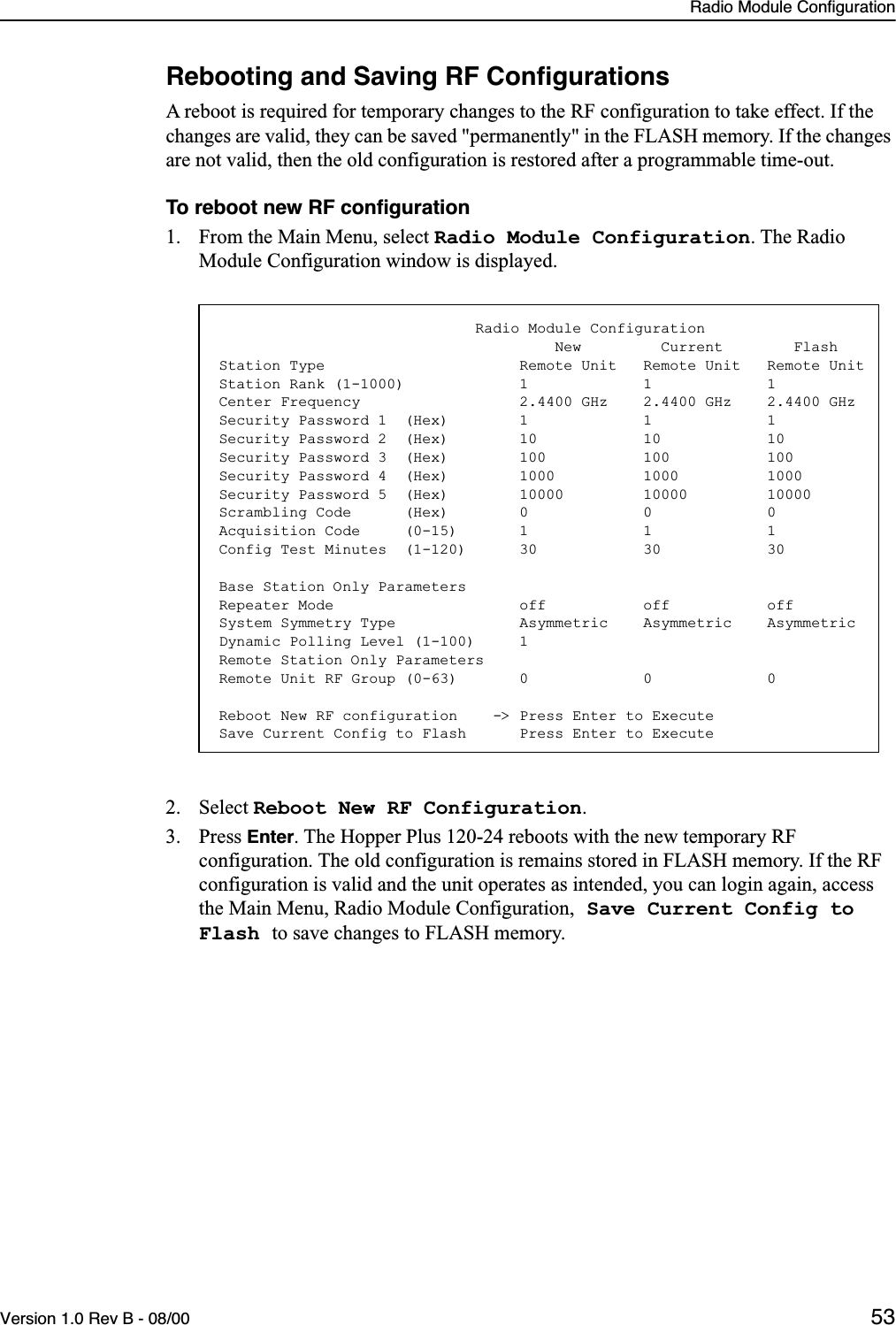
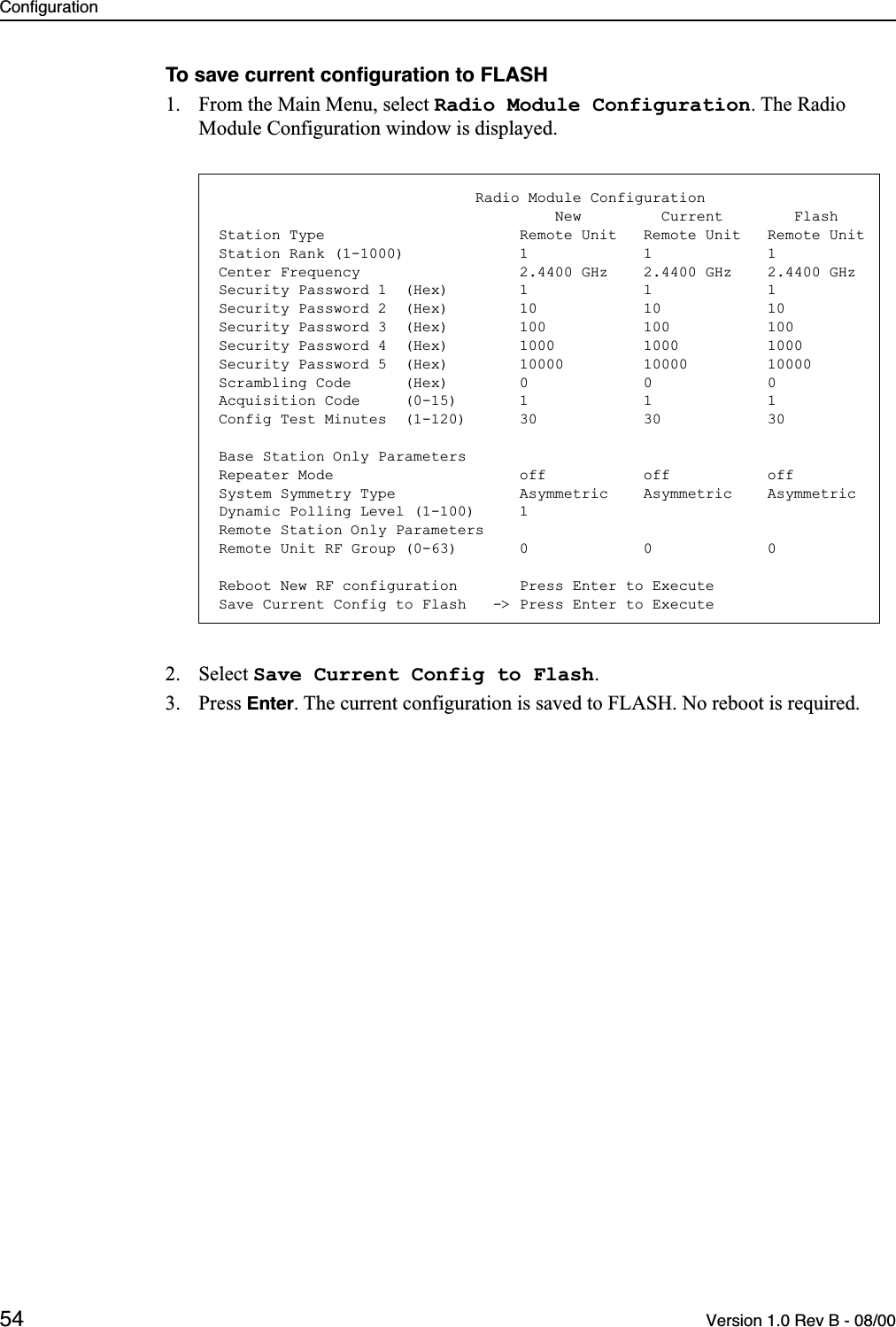
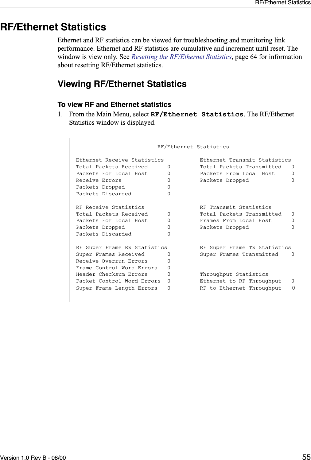
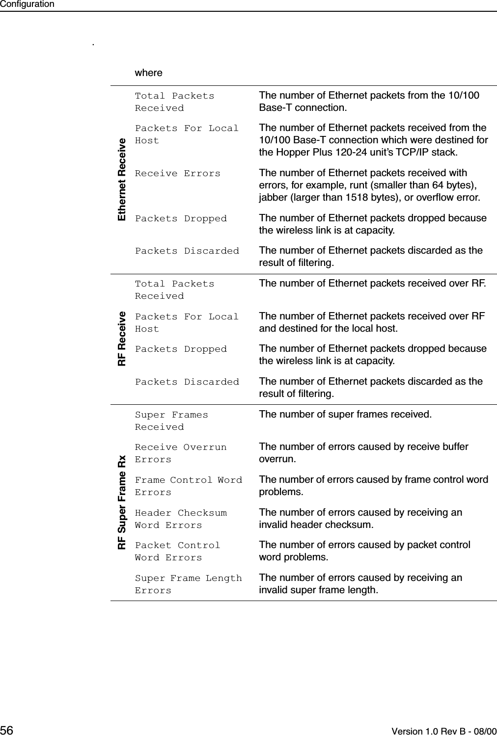
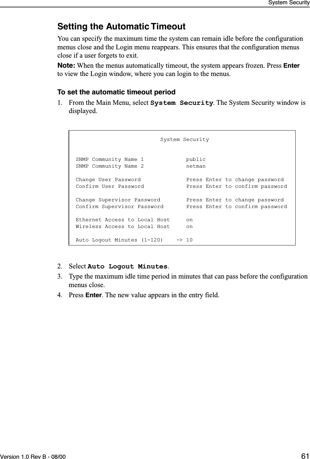
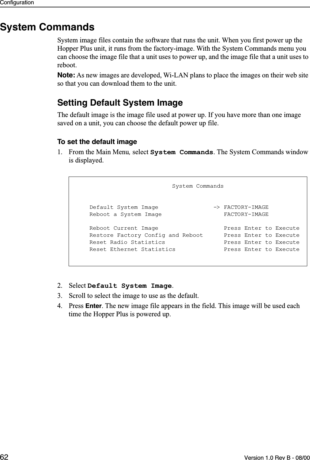
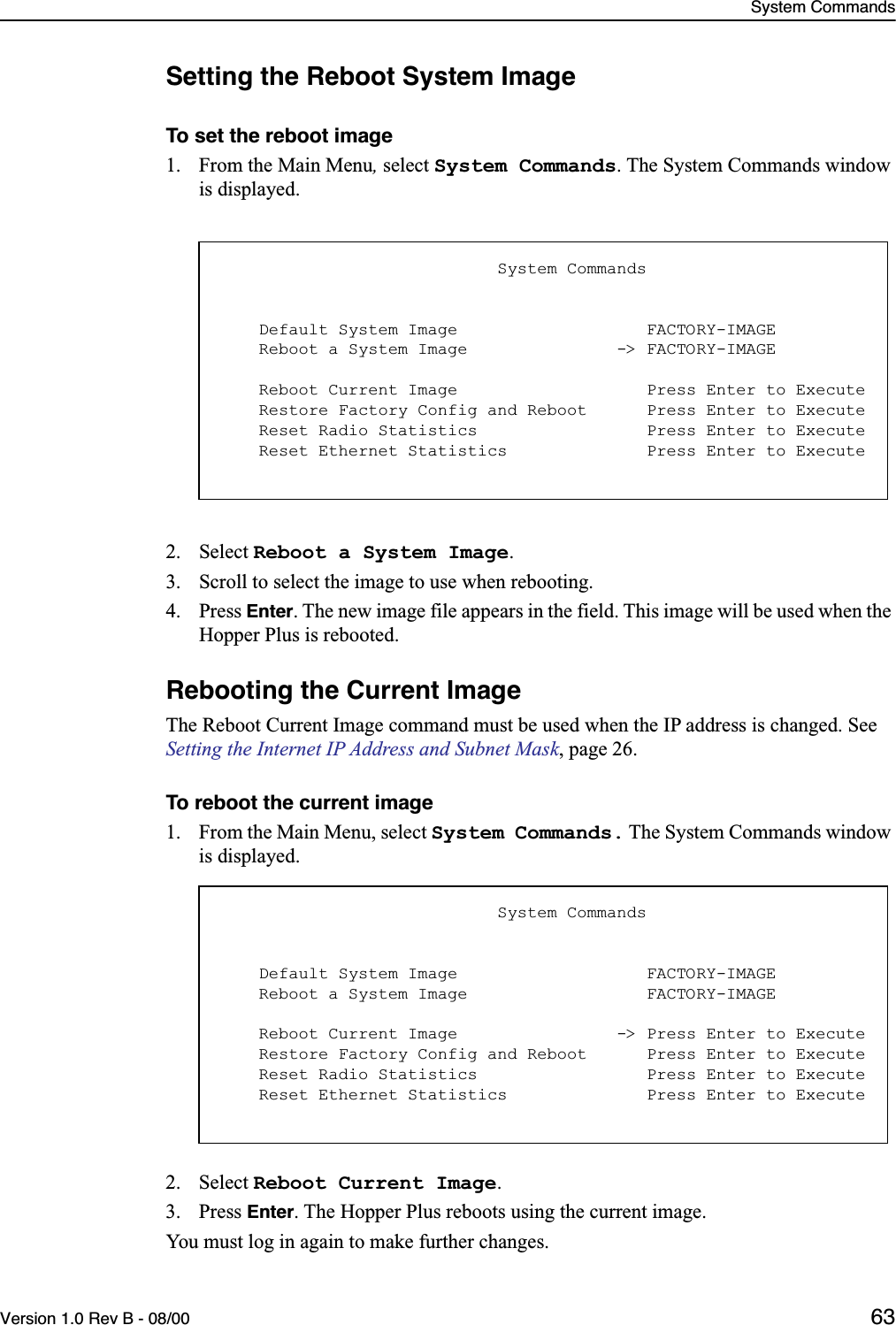
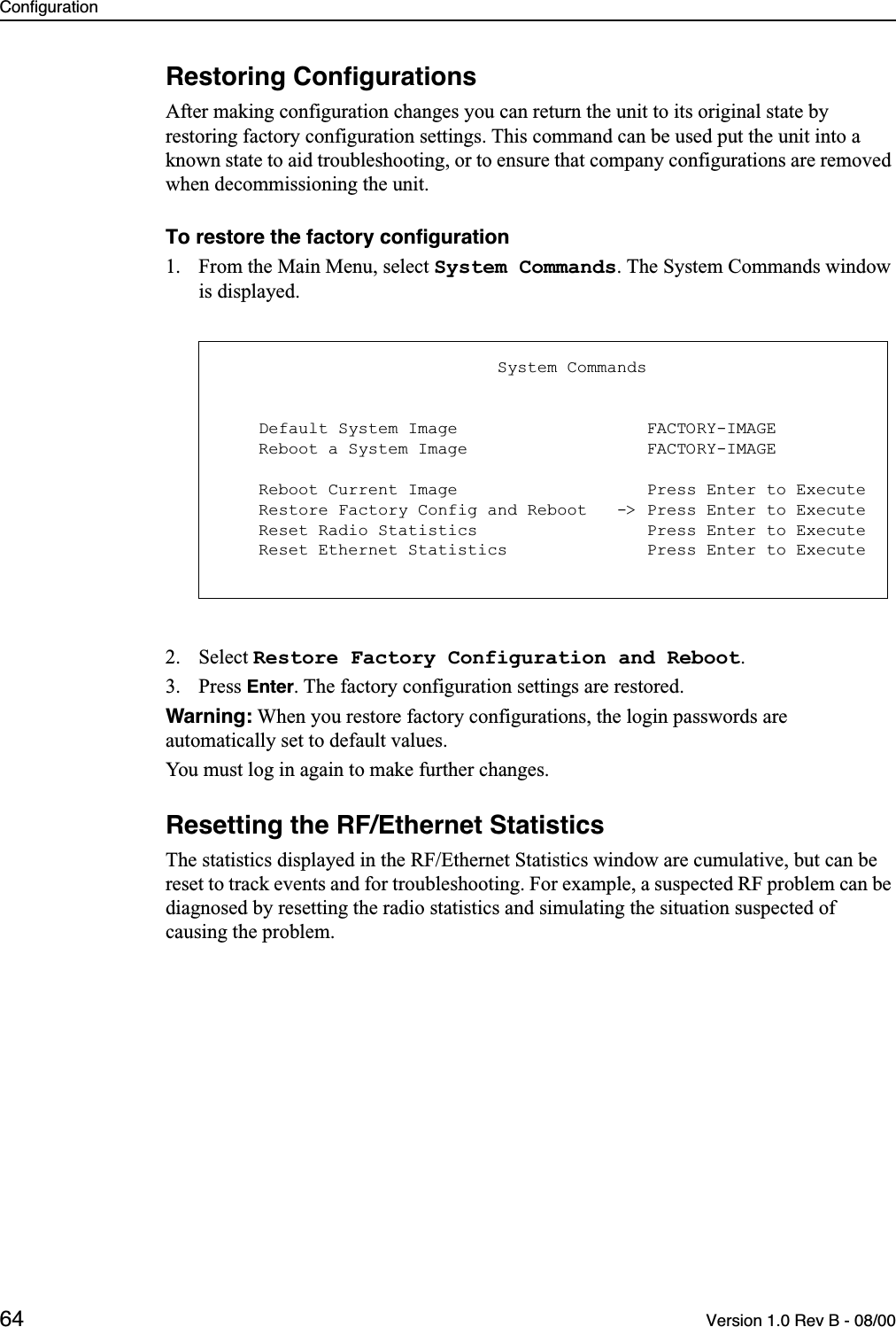
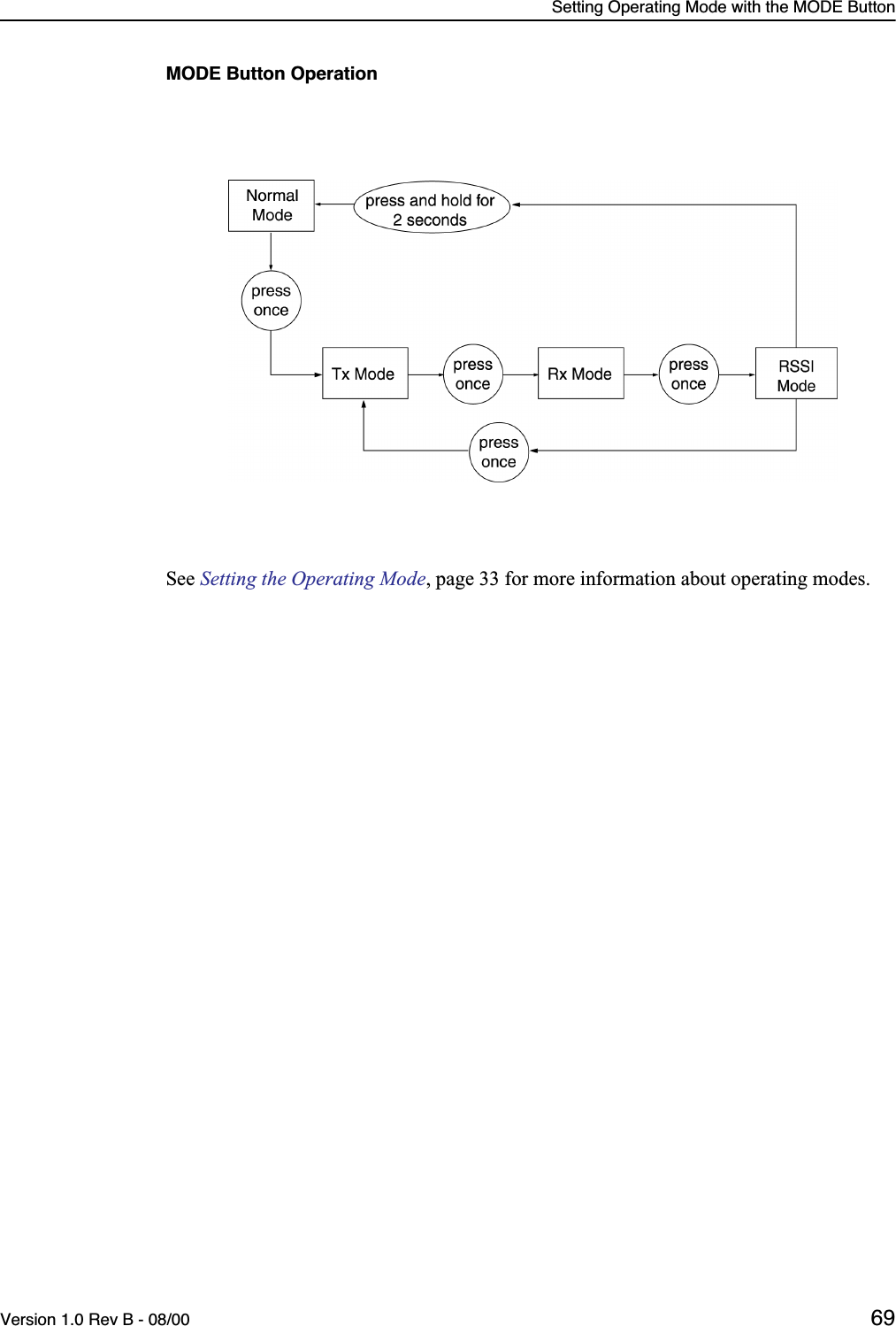
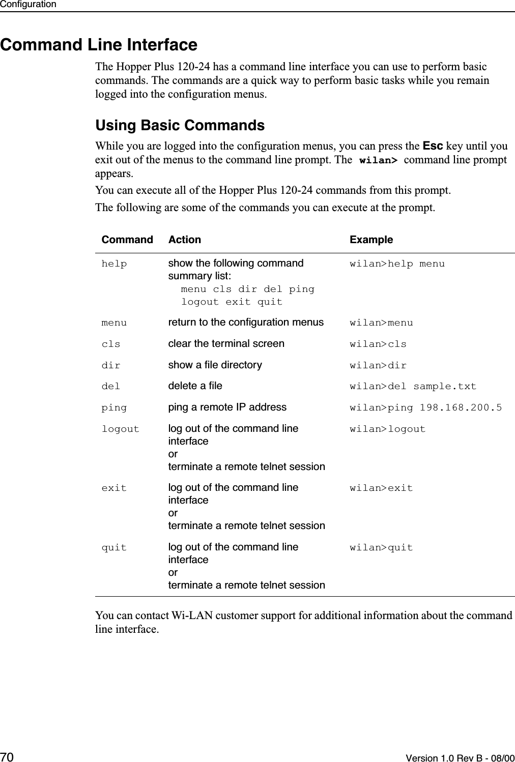
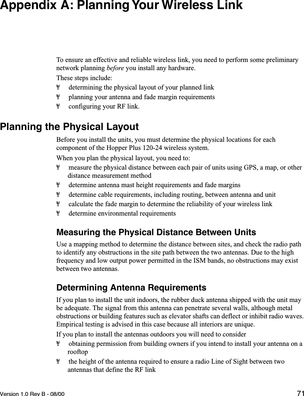
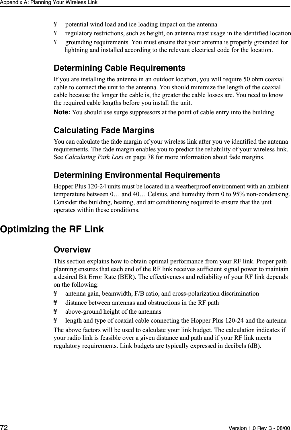
User Manual
Discussion / Help
Navigation