Wi Lan EB01 Wireless Ethernet Bridge User Manual Hopper 120 24
Wi Lan Inc Wireless Ethernet Bridge Hopper 120 24
Wi Lan >
Users Manual with RF safety statement

Hopper Plus 120-24
Wireless Ethernet Bridge
Installation and
Configuration Guide
Version 1.0 Rev B
08/00
Version 1.0 Rev B - 08/00
i
Contents
Notices ..................................................................................... v
Copyright Notice ........................................................................................ v
Regulatory Notice ...................................................................................... v
Other Notices ............................................................................................ vi
Contacting Wi-LAN ................................................................................... vi
Contacting Customer Support vi
Description .............................................................................. 1
Hopper Plus 120-24 Wireless Ethernet Bridge ..........................................1
Making a Wireless Bridge 1
Creating a Wireless Network 2
About Hopper Plus Units 2
Hardware Description ................................................................................3
Shipping Package Contents 3
Hopper Plus 120-24 Unit 3
Hopper Plus 120-24 Specifications ............................................................6
Installation ............................................................................... 9
Basic Installation Steps ..............................................................................9
Configuring a Unit as a Base ...................................................................10
Testing Basic Operation ..........................................................................11
Performing a Bench Test 11
Performing a Simple Network Test 13
Configuration ........................................................................ 15
Accessing the Main Menu ........................................................................16
Accessing Main Menu with MANAGEMENT Port 16
Accessing Units via telnet 17
Setting VT100 Arrows 18
Configuring with the Main Menu ..............................................................19
Unit Identification .....................................................................................20

ii
Version 1.0 Rev B - 08/00
Viewing Unit Identification 20
Setting Unit Identification 21
Hardware/Software Revision ................................................................... 23
Viewing System Revision Information 23
System Software ROM Images ............................................................... 24
Viewing System Software ROM Images 24
Current System Status ............................................................................ 25
Viewing Current System Status 25
IP Network Configuration ........................................................................ 26
Setting the Internet IP Address and Subnet Mask 26
Setting the Default Gateway IP Address 27
Setting the SNMP NMS Trap IP Address 28
IP Filter Configuration .............................................................................. 29
RF Station Configuration ......................................................................... 32
Setting Test Mode Time 32
Setting the Operating Mode 33
Setting the RF Transmit Status 35
Setting the Link Monitor Period 36
Setting Maximum Remote Distance (Base Station Only) 37
Setting Link Monitor Remote Station Rank
(Base Station Only) 38
Setting Throttling (Remote Station Only) 40
Radio Module Configuration .................................................................... 41
Setting the Station Type 42
Setting the Station Rank 43
Setting the Center Frequency 44
Setting Security Passwords 45
Setting the Scrambling Code 46
Setting the Acquisition Code 47
Setting Config Test Minutes 48
Setting Repeater Mode (Base Station Only) 49
Setting System Symmetry Type (Base Station Only) 50
Setting Dynamic Polling Level (Base Station Only) 51
Setting Remote Unit RF Group 52
Rebooting and Saving RF Configurations 53
RF/Ethernet Statistics .............................................................................. 55
Viewing RF/Ethernet Statistics 55
System Security ...................................................................................... 58
Setting Community Names 58
Setting Login Passwords 59
Setting Remote Access 60
Setting the Automatic Timeout 61
System Commands ................................................................................. 62
Setting Default System Image 62
Setting the Reboot System Image 63
Rebooting the Current Image 63
Restoring Configurations 64

Version 1.0 Rev B - 08/00
iii
Resetting the RF/Ethernet Statistics 64
Link Monitor Display .................................................................................66
Viewing Link Monitor Statistics 66
Logout ......................................................................................................67
Logging Out 67
Setting Operating Mode with the MODE Button ......................................68
Using the MODE Button 68
Command Line Interface .........................................................................70
Using Basic Commands 70
Appendix A: Planning Your Wireless Link ......................... 71
Planning the Physical Layout ...................................................................71
Measuring the Physical Distance Between Units 71
Determining Antenna Requirements 71
Determining Cable Requirements 72
Calculating Fade Margins 72
Determining Environmental Requirements 72
Optimizing the RF Link .............................................................................72
Overview 72
Working with System Gain 74
Calculating EIRP (Effective Isotropically Radiated Power) 75
Optimizing Antenna Gain 76
Calculating Propagation Loss 76
Working with the Fresnel Zone 76
Calculating Cable Loss 77
Calculating Path Loss 78
Working with the Fade Margin 78
Link Budget Example ...............................................................................79
Antenna Basics ........................................................................................80
Antenna Parameters 80
Implementation Considerations 81
Selecting Antennas 82
Wi-LAN’s Antenna Selection 82
Antenna Installation Factors 82
Minimal Clearance Above Obstructions 84
Installing Antennas 84
Fine-tuning Antennas 85
Co-locating Units 85
Appendix B: Using HyperTerminal .....................................87
Starting HyperTerminal ............................................................................87
Determining the Communications Port ....................................................91
Appendix C: Configuring a Simple Data Network .............93

iv
Version 1.0 Rev B - 08/00
Checking the Network Adaptor Installation ............................................. 93
Configuring the Network .......................................................................... 94
Enabling the Sharing Feature on the Hard Disk Drive ............................ 97
Appendix D: SNMP MIB ....................................................... 99
About SNMP MIB .................................................................................... 99
Wi-LAN Object Identifier Nodes ............................................................ 100
Using Object Identifier Nodes ............................................................... 101
Appendix E: Technical Reference Information ................ 111
Front Panel LEDs .................................................................................. 111
Power Connector Pinout ....................................................................... 112
Glossary .............................................................................. 113
Index .................................................................................... 121
Version 1.0 Rev B - 08/00
v
Notices
Copyright Notice
Copyright' August 2000 Wi-LAN, Inc.
All rights reserved.
This guide and the application and hardware described herein are furnished under license
and are subject to a confidentiality agreement. The software and hardware can be used
only in accordance with the terms and conditions of this agreement.
No part of this guide may be reproduced or transmitted in any form or by any means
electronic, mechanical, or otherwise, including photocopying and recording without the
express written permission of Wi-LAN, Inc.
While every effort has been made to ensure that the information contained in this guide is
correct, Wi-LAN, Inc. does not warrant the information is free of errors or omissions.
Information contained in this guide is subject to change without notice.
Regulatory Notice
The Hopper Plus 120-24 product presented in this guide complies with the following
regulations and/or regulatory bodies:
¥ RSS-210 and/or RSS-139 of Industry Canada
¥ FCC Part 15
¥ CEPT/ERC Recommendations, ETS 300-328,
ETS 300-826, and EN 60950
Operation is subject to the following two conditions:
¥ this device may not cause interference, and
¥ this device must accept any interference, including interference that may cause
undesired operation of the device.
This equipment generates, uses, and radiates radio frequency and, if not installed and used
in accordance with this guide, may cause harmful interference to radio communications.
However, there is no guarantee that interference will not occur in a particular installation.
If this equipment does cause harmful interference to radio or television reception, which
can be determined by turning the equipment off and on, the user is encouraged to try to
correct the interference by one or more of the following methods:
¥ reorient or relocate the receiving antenna,
¥ increase the separation between the equipment and receiver.
¥ connect equipment to an outlet on a circuit different from that to which the receiver is
connected.

Notices
vi
Version 1.0 Rev B - 08/00
¥ consult the dealer or an experienced radio/TV technician for help.
¥ selecting and testing different channels, if employing 2.4 GHz equipment.
As the Hopper Plus 120-24 is used on a license-exempt, non-frequency coordinated,
unprotected spectrum allocation, and thus can be subject to random unidentified
interference, applications must not be those of a primary control where a lack of
intercommunication could cause danger to property, process, or person. An alternative
fail-safe should be designed into any system to ensure safe operation or shut down, should
communication be lost for any reason.
Other Notices
¥ Changes or modifications to the equipment not expressly approved by Wi-LAN, Inc.,
could void the user s authority to operate the equipment.
¥ Appropriately shielded remote I/O serial cable with the metal connector shell and
cable shield properly connected to chassis ground shall be used to reduce the radio
frequency interference.
¥ FCC radio frequency exposure limits may be exceeded at distances closer than 23
centimeters from the antenna of this device.
¥ All antenna installation work shall be carried out by a knowledgeable and professional
installer.
¥ Use only a power adapter approved by Wi-LAN.
Contacting Wi-LAN
You can contact Wi-LAN applications engineers to help troubleshoot your Wi-LAN
products and to plan your wireless network applications.
Contacting Customer Support
You can contact Wi-LAN customer support at the locations listed below:
You can also contact the Wi-LAN dealer or representative in your region. Phone or email
Wi-LAN for information about the dealer in your area.
Mailing Address
Wi-LAN, Inc.
Suite 300, 801 Manning Road N.E.
Calgary, Alberta CANADA
T2E 8J5
Tel: +1-403-273-9133
Canada and USA Call toll free: 1-800-258-6876
Available from: 8:00 a.m. to 5:00 p.m. (GMT-7:00)
Outside North America Call: +1-403-273-9133
Available from: 8:00 a.m. to 5:00 p.m. (GMT-7:00)
All locations Send an e-mail message to:
techsupport@wi-lan.com
Version 1.0 Rev B - 08/00
1
Description
Hopper Plus 120-24 Wireless Ethernet Bridge
The Hopper Plus 120-24 is a wireless Ethernet bridge that provides high-speed, wireless
connectivity at a fraction of the cost of wired solutions. It uses multi-code direct sequence
spread spectrum technology over the license-exempt, 2.4 - 2.4835 GHz ISM radio band.
The maximum data rate is 12.0 Mbps.
The Hopper Plus 120-24:
¥ provides wireless connectivity at speeds up to eight times faster than regular T1 lines,
making the Hopper Plus ideal for providing high-speed Internet access or for wirelessly
extending existing communications infrastructures.
¥ supports point-to-point and point-to-multipoint networks. Contentionless polling ensures
efficient access to remote data networks.
¥ is self-contained and easy to use. Simply connect a Hopper Plus 120-24 to each LAN
segment, and the unit automatically learns where nodes are located on the network and
performs dynamic packet filtering to ensure the local LAN traffic does not overload the
wireless connection.
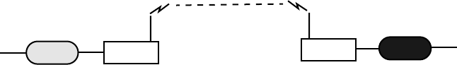
Making a Wireless Bridge
The simplest example of using the Hopper Plus 120-24 is a point-to-point wireless bridge,
which requires a minimum of two units: a base unit and a remote unit. The units make a
high-speed wireless communication link between two wired network segments.
Point-to-Point Wireless Bridge.
Base
Wired Network
RemoteRouter
Main Wired Network
Router
or
Repeater
Hub
Switch
Firewall
Switch
Hub
Firewall
Wireless Link
Description
2
Version 1.0 Rev B - 08/00
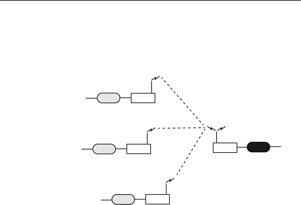
Creating a Wireless Network
You can create a wireless network by adding remotes and taking advantage of the point-to-
multipoint capabilities of the Hopper Plus 120-24. Up to 255 remote units can be
contained in a wireless network.
Point-to-Multipoint Wireless Network
About Hopper Plus Units
Base Station:
A Hopper Plus 120-24 can operate as a remote unit or a base station,
however, at least one unit in the network
must
be configured as a base. A base station is
the central control unit of the wireless network. The base station polls all remote units and
controls how traffic is routed to and from remotes. The base usually connects to a major
access point of the wired network. The antenna of the base station must be capable of
transmitting and receiving radio signals to and from all the remote units in a system. If
remotes are spread over a large area, an omni-directional antenna is usually required.
Remote Units:
Remote units link wired segments of the network wirelessly to the main
network (via the base station). Remotes can limit the amount of data passed by the remote
(a function called throttling), and they can filter specific data packets. Because remote
units need to communicate only with the base station, their antennas can be more
directional and have higher gains than base antennas.
Repeaters:
A base unit can also be configured as a repeater. A repeater is needed when
remote units cannot communicate directly with each other, but direct transfers of data
between them are necessary (as in a true WAN). When configured as a repeater, the base
station passes data packets between remote stations based on the remote group status and
the MAC (Media Access Control) address filter. Remote stations ignore the packets they
hear from other remotes, and listen only to the repeated packets from the base. See
Setting
Repeater Mode (Base Station Only)
, page 49 for more information.
Base
RemoteRouter
RemoteRouter
Wired Network
Wired Network
Wired Network
RemoteRouter
Main Wired Network
Router
or
Repeater
Hub
Switch
Hub
Switch
Firewall
Firewall
Switch
Hub
Firewall
Switch
Hub
Firewall

Hardware Description
Version 1.0 Rev B - 08/00
3
Hardware Description
Shipping Package Contents
When you receive a Hopper Plus, the shipping package contains the following items:
¥ Hopper Plus 120-24 unit
¥ indoor antenna
¥ power supply cord
¥ AC/DC power adapter
¥ straight-through ethernet cable (RJ45)
¥ crossover ethernet cable (RJ45)
¥ DB9 (M) to DB25 (F) adaptor
¥ RS-232 DB9 serial cable
¥ Installation and Configuration Guide
¥ Warranty Card
If any of the above items are not included in the Hopper Plus 120-24 shipping package,
contact Wi-LAN customer support immediately.
Hopper Plus 120-24 Unit
The Hopper Plus 120-24 has connectors and LEDs on the front and back panels.
Front Panel
LED IndicatorsRS-232 Management Port
Description
4
Version 1.0 Rev B - 08/00
The the front panel connector and LEDs are described below. The color of a LED
indicates its status See
Front Panel LEDs
, page 111 for detailed information.
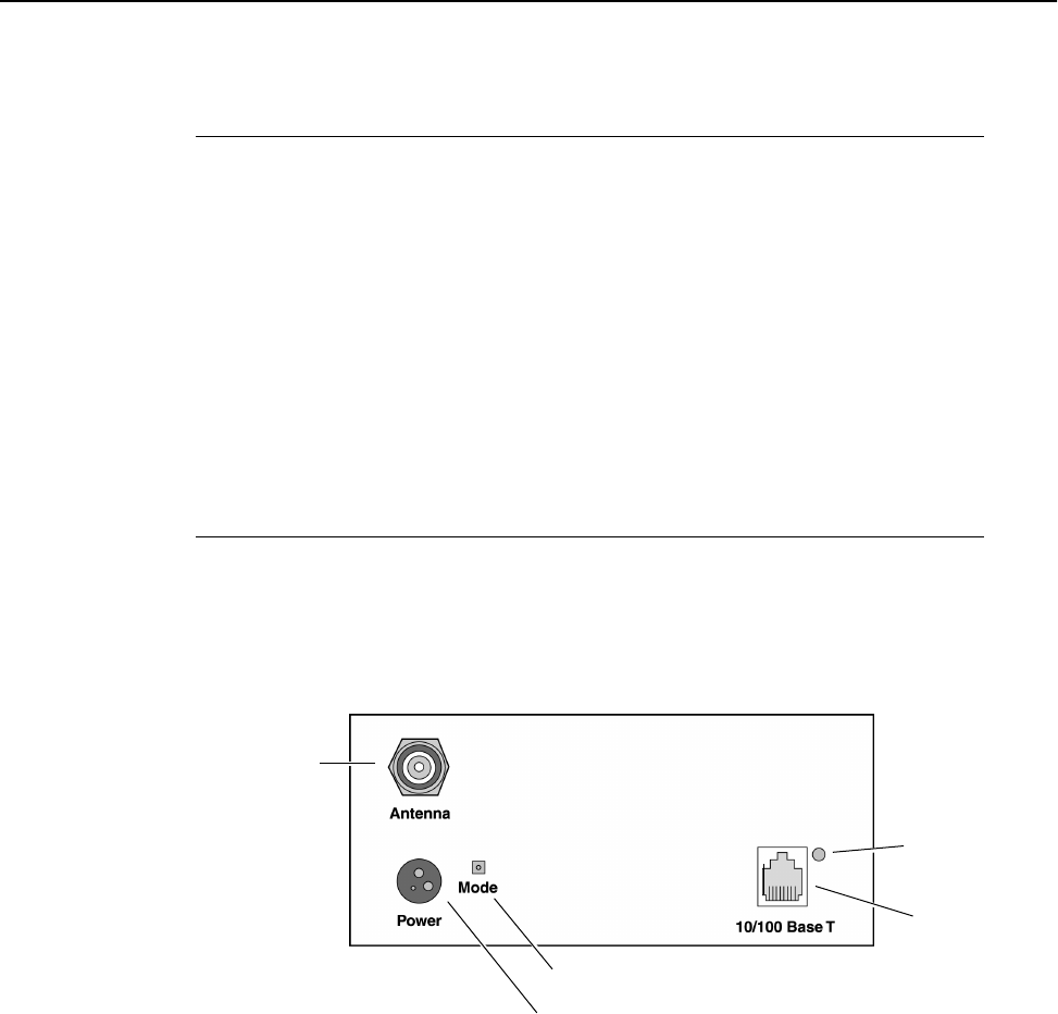
Connectors for power, antenna and wired network are located on the back panel, as well as
a mode button and a link LED.
Rear Panel
MANAGEMENT
Port
An RS-232, DB9 connector used to communicate with a
PC. Use this port to configure, test and set up the Hopper
Plus.
AIR LED Color of LED indicates the status of the wireless link
during transmit, receive, or listen. Normal color: Orange.
MODE LED Color of LED indicates the test status of the unit when
unit is in test mode. Normal color: Off.
WIRE LED Color of LED indicates the status of the wire link during
transmit, receive, transmit and receive, or listen. Normal
color: Green, Red, Orange or Off.
POWER LED Shows the status of the unit’s power. Normal color:
Green.
MODE button
LINK LED
Network
Port
Power Connector
Antenna
(TNC)
Connector

Hardware Description
Version 1.0 Rev B - 08/00
5
Items located on the back panel are described below:
ANTENNA Connector The antenna connector is located at the top left of the rear
panel. It is TNC (Threaded N-type Connector) male or
female. This port should always be connected to an
antenna directly or through a 50 ohm coaxial cable.
POWER Connector 3-pin power connector. See
Power Connector Pinout
, page
112 for detailed pinout illustration.
MODE Button The mode button can be used to set the operating mode of
a unit without a terminal. See
Setting Operating Mode with
the MODE Button
, page 68 for information about the mode
button.
10/100 BASET A standard RJ45 female connector. To connect to a PC
Ethernet card, you must use the crossover twisted-pair
cable (provided). To connect to a hub, use a straight-
through twisted-pair cable.
LINK LED The color of the LED indicates the data rate and status of
the twisted-pair connection.
Green = 10 BaseT link, functioning properly.
Orange = 100 BaseT link, functioning properly.
Off = No link.

Description
6
Version 1.0 Rev B - 08/00
Hopper Plus 120-24 Specifications
General Specifications
Modulation Method: Multi-Code Direct Sequence Spread
Spectrum
Wireless Data Rate: 12 Mbps
RF Frequency Range: 2.4 - 2.4835 MHz (unlicensed ISM band)
Number of Center Frequencies: 7 independent, 3 concurrent
Power Requirements: 48W @ 12VDC (via 110/240 VAC 50/60 Hz
adaptor)
Physical Dimensions: 24 x 8 x 21 centimeters
(9.5 x 3.2 x 8.3 inches)
Radio Specifications
Antenna Connector: Reverse TNC
TNC
Output Power: +18.5 dBm
Receiver Sensitivity: – 83 dBm
Processing Gain: >10 dB
Network Support
Packet Format: IEEE 802.3 and Ethernet II
(High-level protocol transparent)
LAN Connection: 10/100 BaseT (autonegotiates)
Bridge Functionality: Local Packet Filtering (self-learning), Static IP
address filtering, throttling capability
Wireless Networking Protocols
Network Topologies: Point-to-Point, Point-to-Multipoint,
Multipoint-to-Multipoint
Repeater Mode: User Configurable
RF Collision Management: Dynamic Polling, with Dynamic Time
Allocation
Security
Data Scrambling: User Configurable
Data Security Password: Security password of up to 20 bytes in length
(10
48
combinations)
Configuration, Management, and Diagnostics
Configuration Methods: SNMP, Telnet, and RS-232 Management Port

Hopper Plus 120-24 Specifications
Version 1.0 Rev B - 08/00
7
SNMP: Version I compliant (RFC 1157), MIB standard
and enterprise (RFC 1213)
Management Port Functionality: Supports system configuration, security,
access control, wireless LAN diagnostics and
management, menu-driven ASCII interface via
RS-232 DB-9.
Environment
Units must be located in a weatherproof
environment with an ambient temperature
from 0 to 40º Celsius and humidity 0 – 95%
non-condensing.

Description
8
Version 1.0 Rev B - 08/00
Version 1.0 Rev B - 08/00
9
Installation
Basic Installation Steps
The following basic steps are required to successfully install your Hopper Plus 120-24
wireless bridge. For detailed information about performing the steps, see the references
provided.
1. Plan your network. Before you install any equipment, you need to determine the phys-
ical layout of your wireless link, plan antenna and fade margin requirements, and opti-
mize the wireless link. For help, refer to Appendix A: Planning Your Wireless Link or
contact Wi-LAN customer support. You will require a minimum of two Hopper Plus
units (one configured as a base, and one configured as a remote) to create a wireless
link between two wired network segments.
2. Check the contents of each shipping carton to ensure all the required parts are
present. See Hardware Description, page 3 for a list of parts.
3. Configure one Hopper Plus unit as a base station. See Configuring a Unit as a Base,
page 10. (Units come from the factory configured as remotes).
4. Test the basic operation of the bridge. See Testing Basic Operation, page 11 for more
information.
5. Place the units in their field locations and connect them to antennas, the wired net-
work, and power.
Warning: External antennas must be professionally installed and follow accepted safety,
grounding, electrical, and civil engineering standards.
Always connect an antenna to the ANTENNA port before you power up a unit or you
can damage a unit.
6. Configure each unit as follows:
l View and set the Unit Identification. See Viewing Unit Identification, page 20
and Setting Unit Identification, page 21.
l Set the Station Rank. See Setting the Station Rank, page 43.
l Set the Center Frequency. See Setting the Center Frequency, page 44.
l Set the Security Passwords. See Setting Security Passwords, page 45.
l Set the Acquisition Code. See Setting the Acquisition Code, page 47.
l Set the Remote Unit RF Group. See Setting Remote Unit RF Group, page 52.
l Change the default passwords. See Setting Login Passwords, page 59.
7. Test the installed wireless network using ping, ftp, or file transfers.
If you have problems, contact Wi-LAN customer support.
Installation
10 Version 1.0 Rev B - 08/00
Configuring a Unit as a Base
Hopper Plus 120-24 units are delivered from the factory configured as remote units. To
make a wireless bridge, you need to configure one unit as a base unit (base station). All
other units in the wireless network can remain configured as remote units (so you do not
need to change the "station type" of remotes). No user software is required to install a unit.
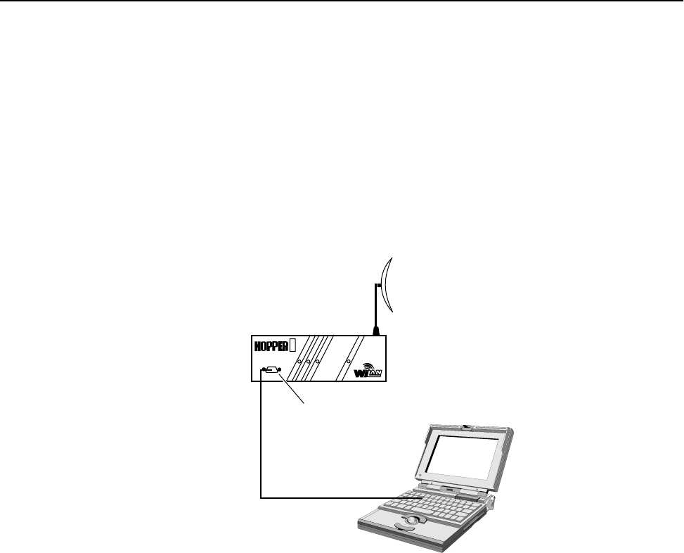
To configure one unit as a base unit
1. Connect a PC to the MANGAGEMENT port to the Hopper Plus unit that will be the
base unit.
Connecting PC to MANAGEMENT Port
2. Start the terminal emulation program (for example, HyperTerm¤—see Appendix B:
Using HyperTerminal, page 87).
3. Press Enter. Enter the default password (choose supervisor). The Main Menu is
displayed.
AIR
MODE
WIRE
POWER
PLUS
Hopper Plus Unit
PC
Serial Cable
to PC COM port
Management Port

Testing Basic Operation
Version 1.0 Rev B - 08/00 11
4. Select Radio Module Configuration. The Radio Module Configuration
window is displayed.
5. Select Station Type.
6. Select Base Unit and press Enter.
7. Select Reboot New RF configuration and press Enter. The unit reboots.
8. Log in to the unit.
9. Select Save Current Config to Flash and press Enter. The settings are stored in flash
memory.
10. Select Logout from the Main Menu to exit.
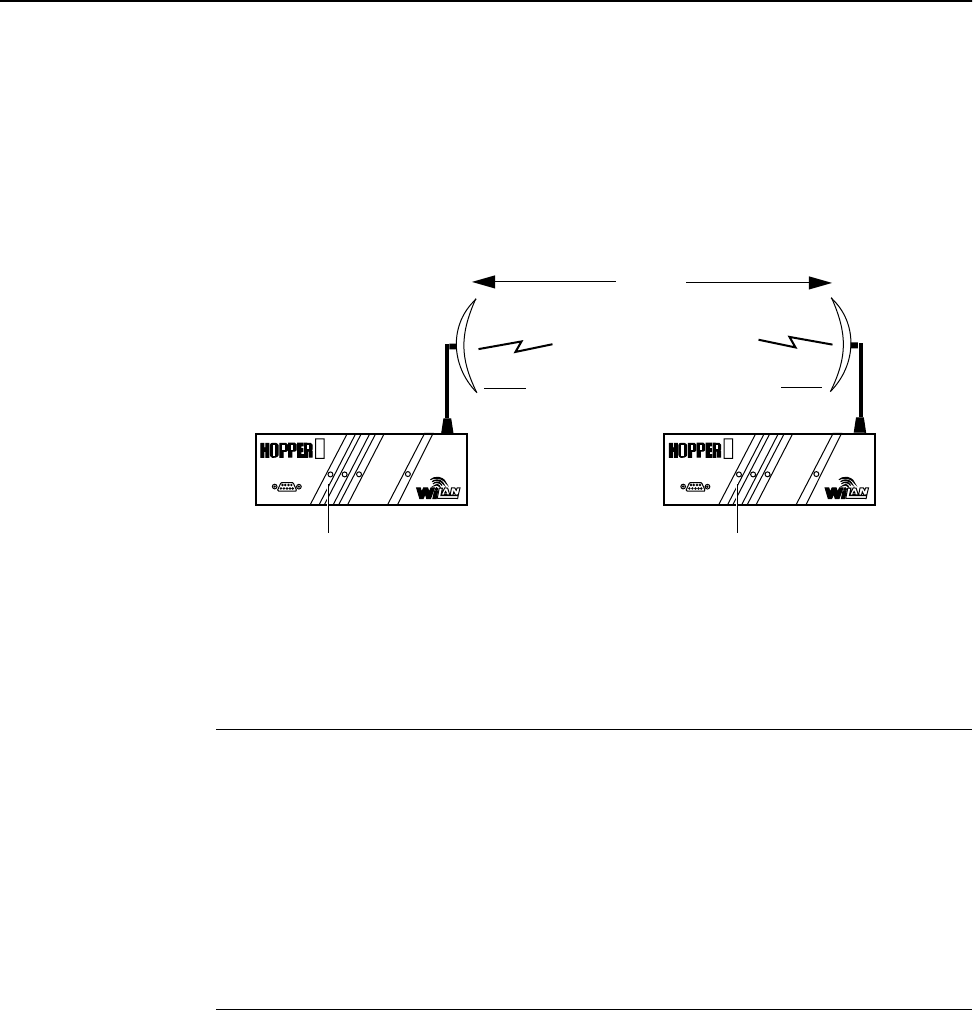
Testing Basic Operation
Wi-LAN recommends that you bench test units before placing them the field. You should
first perform a standalone test, then test the bridge as part of a simple network.
Once one unit has been set to a base unit, it can then be used to test all other remote units
without making configuration changes to the remotes.(Units are shipped from factory
configured as remotes).
Performing a Bench Test
To perform a bench test of the bridge
1. Ensure that you have configured a unit as a base unit.
2. Ensure that the station type of all other units is Remote Unit. See Setting the Station
Type, page 42.
Radio Module Configuration
New Current Flash
Station Type -> Remote Unit Remote Unit Remote Unit
Station Rank (1-1000) 1 1 1
Center Frequency 2.4400 GHz 2.4400 GHz 2.4400 GHz
Security Password 1 (Hex) 1 1 1
Security Password 2 (Hex) 10 10 10
Security Password 3 (Hex) 100 100 100
Security Password 4 (Hex) 1000 1000 1000
Security Password 5 (Hex) 10000 10000 10000
Scrambling Code (Hex) 0 0 0
Acquisition Code (0-15) 1 1 1
Config Test Minutes (1-120) 30 30 30
Base Station Only Parameters
Repeater Mode off off off
System Symmetry Type Asymmetric Asymmetric Asymmetric
Dynamic Polling Level (1-100)
Remote Station Only Parameters
Remote Unit RF Group (0-63) 0 0 0
Reboot New RF configuration Press Enter to Execute
Save Current Config to Flash Press Enter to Execute
Installation
12 Version 1.0 Rev B - 08/00
3. Locate base unit and one remote unit at least twenty meters apart with a clear line of
sight between them.
4. Attach the provided indoor antenna to the antenna port of each unit, and orient the
antenna vertically.
5. Power up both units.
Basic Test Setup
6. Observe the AIR LED of each unit and look for normal status. A normal status is
indicated when the AIR LEDs on the base and the remote unit are both orange. The
status of the AIR LED is indicated as follows.
Note: If antennas are too close together, the strong transmit signal will cause distortion at
the receiveing unit. You can fine-tune antennas by physically moving the antenna. When
the remote antenna is correctly aligned, the AIR LED is orange, indicating that data from
the base station is being received and acknowledged.
7. Run the Link Monitor test on the remote unit. See Setting Link Monitor Remote Station
Rank (Base Station Only), page 38. Check for RSSI below 40% and BER = 0. If you
have problems ensure that the unit is configured to its basic default settings or contact
Wi-LAN customer support.
8. Disable Link Monitor.
9. When both AIR LEDs are orange, power down both units and perform the simple
network test. See Performing a Simple Network Test, page 13.
Orange (both stations) The stations are continuously sending and receiving
sync packets.
Red (base station) The stations are configured incorrectly, and the base
station is transmitting without receiving
acknowledgment.
Green (remote station) The stations are configured incorrectly, and the remote
station is receiving packets to which it cannot respond.
Off Nothing is being received (by the remote) or transmitted
(from the base).
AIR
MODE
WIRE
POWER
PLUS
20m
minimum
AIR LED = orange
Base Unit Remote Unit
AIR
MODE
WIRE
POWER
PLUS
AIR LED = orange
Indoor
Antenna
Indoor
Antenna
Testing Basic Operation
Version 1.0 Rev B - 08/00 13
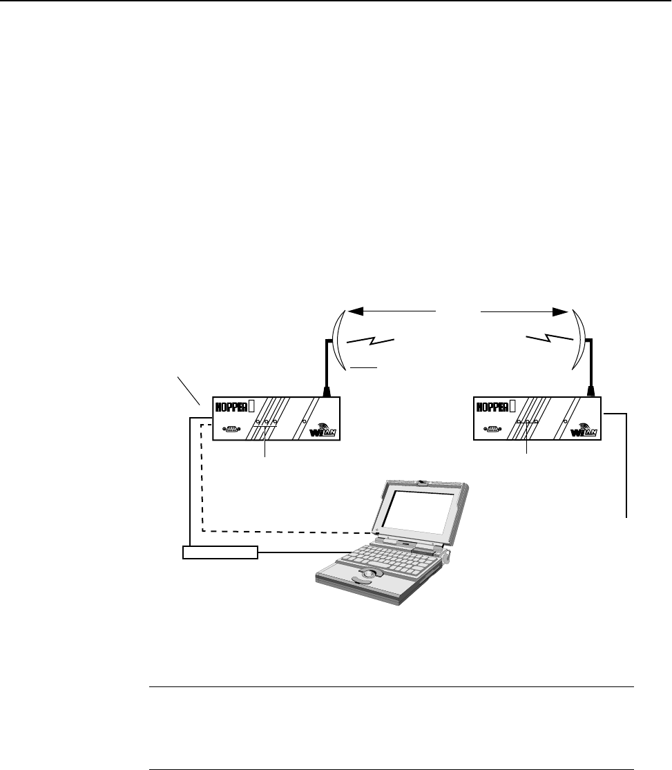
Performing a Simple Network Test
To perform a simple network test
1. Connect one Hopper Plus 120-24 to the LAN.
2. Connect a PC from your network directly to the other Hopper Plus 120-24 (connect
with a 10/100 BaseT crossover cable if no hub is used).
Note: Cabling between 10/100 BaseT nodes is generally done through a net-
work hub. To make a direct 10/100 BaseT connection between a Hopper Plus
120-24 and a PC, you need a standard crossover cable (swap pins 1&3; 2&6).
Simple Network Test Setup
3. Power up each Hopper Plus 120-24 unit. Initially the LEDs should appear as follows:
4. Create some network traffic to test the bridge (for example, transfer a file across the
bridge). The WIRE LED indicates the activity. See Appendix C: Configuring a Simple
Data Network, page 93 for more information.
5. Repeat the steps for each remote you install.
6. To test network configuration further, see Appendix C: Configuring a Simple Data
Network, page 93 for moreinformation about configuring simple peer-to-peer
networks.
POWER LED Green
MODE LED Off
AIR LED Orange
AIR LED = orange
Base Unit Remote Unit
MODE LED = Off
POWER LED = Green
AIR LED = orange
MODE LED = Off
POWER LED = Green
PC
LAN
10/100 BaseT HUB
10 BaseT Cable
Direct 10 BaseT Cable (Crossover)
AIR
MODE
WIRE
POWER
PLUS
AIR
MODE
WIRE
POWER
PLUS
20m
minimum
Indoor
Antenna
Cables connect to
10 BaseT network port
(Straight
Through)
Cable
10 BaseT

Installation
14 Version 1.0 Rev B - 08/00

Version 1.0 Rev B - 08/00 15
Configuration
This section explains how to access and use the main configuration menu (called the
Wi-LAN Hopper Plus 120-24 Main Menu, and shown below). In this section, each item in
the Main Menu is described in the order that it appears in the menu.
Use the Main Menu and your keyboard keys to select, view or change settings. Some
items in the menu simply display information, while others ask you to enter data or make
a selection from a list.
Main Menu
Wi-LAN Hopper Plus 120-24 Main Menu
-> Unit Identification
Hardware/Software Revision
System Software ROM Images
Current System Status
IP Network Configuration
IP Filter Configuration
RF Station Configuration
Radio Module Configuration
RF/Ethernet Statistics
System Security
System Commands
Link Monitor Display
Logout

Configuration
16 Version 1.0 Rev B - 08/00
Accessing the Main Menu
You can access the Main Menu via the MANAGEMENT port or a telnet session.
You can also configure the Hopper Plus 120-24 remotely with the SNMP (Simple
Network Management Protocol) manager. See Appendix D: SNMP MIB, page 99 for
information about SNMP.
Accessing Main Menu with MANAGEMENT Port
To access the Main Menu through the MANAGEMENT port
1. Disconnect the power from the Hopper Plus unit.
2. Connect a serial cable from a DB9 serial port on the PC to the MANAGEMENT port
on the Hopper Plus (adaptors are shipped with the unit). See Configuring a Unit as a
Base, page 10.
3. Start a terminal emulation program (such as Hyperterm) on the PC. See Appendix B:
Using HyperTerminal.
4. Set the terminal emulation program to emulate a VT100 terminal with the following
settings:
¥ COM port PC serial port connected to Hopper Plus unit
¥ Bits per second: 9600
¥ Data bits: 8
¥ Parity: none
¥ Stop bits: 1
¥ Flow control: none
5. Reconnect the power to the Hopper Plus unit.
6. Press Enter. The Login menu is displayed.
7. Type the default password, or type your password.
The Main Menu is displayed.
Login Account Default Password Privileges
User user Read Only
Supervisor supervisor Read and Write
Wi-LAN Hopper Plus 120-24 Login
Software: Rev 0.0.0 (May 25 2000 10:13:37)
Hardware: Rev 0.0.0 (4MB SDRAM, 4MB Intel Flash)
Enter Password:

Accessing the Main Menu
Version 1.0 Rev B - 08/00 17
Accessing Units via telnet
To access units via telnet
1. Ensure that the unit s Internet IP address has been configured, the unit has a working
Ethernet connection, and wire and remote access has been enabled (see Setting
Remote Access, page 60).
2. Ensure that the VT100 Arrows feature in your telnet session is enabled. See Setting
VT100 Arrows, page 18.
3. From a VT100 terminal, or emulation program, type telnet <IP address>
where <IP address> is the address of the unit that you want to configure.
4. Press Enter. The Login menu is displayed.
5. Type the default password (user or supervisor) or type your personal password.
The Main Menu is displayed.
Wi-LAN Hopper Plus 120-24 Login
Software: Rev 0.0.0 (May 25 2000 10:13:37)
Hardware: Rev 0.0.0 (4MB SDRAM, 4MB Intel Flash)
Enter Password:
Configuration
18 Version 1.0 Rev B - 08/00
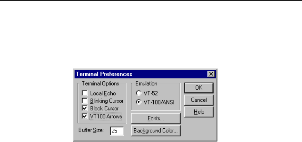
Setting VT100 Arrows
To set the VT100 arrows in Microsoft telnet
1. In the active Microsoft telnet 1.0 session, select Terminal, Preferences from the
menu bar. The Terminal Preferences window is displayed.
2. Click the VT100 Arrows checkbox.
3. Click OK. The VT100 arrows are enabled in the telnet session.
You can now use the keyboard arrow keys to navigate the configuration menus.

Configuring with the Main Menu
Version 1.0 Rev B - 08/00 19
Configuring with the Main Menu
This section describes how to configure units with the Main Menu. Menu items are
presented in the order they appear in the menu shown below.
Main Menu
Wi-LAN Hopper Plus 120-24 Main Menu
-> Unit Identification
Hardware/Software Revision
System Software ROM Images
Current System Status
IP Network Configuration
IP Filter Configuration
RF Station Configuration
Radio Module Configuration
RF/Ethernet Statistics
System Security
System Commands
Link Monitor Display
Logout

Configuration
20 Version 1.0 Rev B - 08/00
Unit Identification
Viewing Unit Identification
You can view a unit s serial number, production date, and MAC address in the Unit
Identification menu. These fields are view only and are set at the factory.
To view unit identification
1. From the Main Menu, select Unit Identification The Unit Identification
window is displayed.
where
Serial Number Unique serial number of the unit (Read Only).
Production Date Date that the unit was produced (Read Only).
Ethernet MAC Address Unique Internet MAC address for the unit
(Read Only).
Unit Identification
Serial Number Serial-Number
Production Date 01-01-2000
Ethernet MAC Address 001030040502
Unit Name/Description -> System Name
Unit Location System Location
Contact Name System Manager's Name

Unit Identification
Version 1.0 Rev B - 08/00 21
Setting Unit Identification
You can configure a unit s name, location, and contact name for system management
purposes. This information could be used to distinguish remote units by their physical
location or by meaningful names rather than the unit s station rank. The unit identification
information does not need to be configured for a working system.
To set unit name/description
1. From the Main Menu, select Unit Identification. The Unit Identification
window is displayed.
2. Select Unit Name/Description.
3. Type in new name or description.
4. Press Enter. The new name or description is displayed in the entry field.
where
Serial Number Unit serial number.
Production Date The production date: MM-DD-YY.
Ethernet MAC
Address
MAC (Media Access Control) address. The physical
Ethernet address.
Unit Identification
Serial Number Serial-Number
Production Date 01-01-2000
Ethernet MAC Address 001030040502
Unit Name/Description -> System Name
Unit Location System Location
Contact Name System Manager's Name

Configuration
22 Version 1.0 Rev B - 08/00
To set unit location
1. From the Main Menu, select Unit Identification. The Unit Identification
window is displayed.
2. Select Unit Location.
3. Type in the new location.
4. Press Enter. The new location appears in the entry field.
To set unit contact name
1. From the Main Menu, select Unit Identification. The Unit Identification
window is displayed.
2. Select Contact Name.
3. Type in a contact or manager name.
4. Press Enter. The new name appears in the entry field.
Unit Identification
Serial Number Serial-Number
Production Date 01-01-2000
Ethernet MAC Address 001030040502
Unit Name/Description System Name
Unit Location -> System Location
Contact Name System Manager's Name
Unit Identification
Serial Number Serial-Number
Production Date 01-01-2000
Ethernet MAC Address 1030040502
Unit Name/Description System Name
Unit Location System Location
Contact Name -> System Manager's Name

Hardware/Software Revision
Version 1.0 Rev B - 08/00 23
Hardware/Software Revision
Viewing System Revision Information
The system revision information shows details about the system including:
¥ version of the Hopper Plus 120-24 hardware
¥ ROM and RAM size
¥ version number of the system image file on the unit
¥ version date of the system image file on the unit
¥ name of the image file running on the Hopper Plus 120-24
To view system revision information
From the Main Menu, select Hardware/Software Revision. The System Revision
Information window is displayed. The window is view only.
where
Hardware The revision number of the Hopper Plus 120-24 unit, and
the RAM and FLASH installed in the unit.
ROM Size The amount of read-only memory in the unit.
RAM Size The amount of random-access memory in the unit. This
value also appears in the Hardware field.
Software The revision number of the system image running on the
unit, the date of the revision, and the size of the file (in
this case FACTORY-IMAGE).
File Name The file name of the system image running on the unit.
System Revision Information
Hardware Rev 0.0.0 (4MB SDRAM, 4MB Intel Flash)
ROM Size 0x400000
RAM Size 0x400000
Software Rev 0.0.0 (Wi-LAN Hopper Plus 120-24 WEBII)
June 26 2000 10:13:37
318452 Bytes
File Name FACTORY-IMAGE

Configuration
24 Version 1.0 Rev B - 08/00
System Software ROM Images
Viewing System Software ROM Images
The System Software ROM Images window shows a list of all images available on the
unit. An image is the embedded software stored in Flash ROM that the unit uses to
operate. The example lists only the Factory-Image, however, several images may be
available for use. As new images become available, Wi-LAN will place the images on
their web site and make them available for downloading by customers.
To view system software ROM images
From the Main Menu, select System Software ROM Images. The System Software
ROM Images window is displayed. The window is view only.
.
where
File Name The names of all system image files stored in the unit.
Revision The revision number of the system image file. Each time
the system image is modified, the revision number
increases by 1 unit. For example, the first revision to the
file would make the revision number 0.0.1.
Date The date the image file was last revised.
Time The time the image file was last revised.
Size The size of the image file in bytes.
Default Image Indicates which image file is the default. This is the
image used at power up. See To set the default image,
page 62 to modify default image.
System Software ROM Images
File Name Revision Date Time Size Default Image
-------------------- -------- ----------- -------- ------ -------------
FACTORY-IMAGE 0.0.0 May 25 2000 10:13:37 306524 Current
More than one image may be listed here

Current System Status
Version 1.0 Rev B - 08/00 25
Current System Status
Viewing Current System Status
The Current System Status window shows administration information such as the time a
unit has been running, and login statistics.
To view current system status
From the Main Menu, select System Current Status. The System Current Status
window is displayed. The window is view only.
.
where
Cumulative Run-Time The number of hours the system has been running
since it was manufactured. This information is
required for maintenance purposes.
Current Run-Time The time duration that has passed since the unit was
last reset or power cycled.
Successful Logins The number of times that the configuration menus
have been successfully accessed.
Unsuccessful Logins The number of times that access to the configuration
menus has failed.
Local User Logged In The access level of the user currently logged into the
configuration menus via the RS-232.
Telnet User Logged
In
The access level of the user currently logged into the
configuration menus via a telnet session.
FTP User Logged In The access level of the user currently logged into the
host FTP server.
System Current Status
Cumulative Run-Time Days: 0 Hours: 7
Current Run-Time Days: 0 00:38:38
Successful Logins 16
Unsuccessful Logins 1
Local User Logged In Supervisor
Telnet User Logged In None
FTP User Logged In None

Configuration
26 Version 1.0 Rev B - 08/00
IP Network Configuration
To remotely manage the Hopper Plus 120-24 units, you need to define the Internet IP
settings.
Setting the Internet IP Address and Subnet Mask
Each Hopper Plus 120-24 unit in a system must have a valid Internet IP address and
subnet mask for communication via TCP/IP.
To set the Internet IP address
1. From the Main Menu, select IP Network Configuration. The Network
Configuration window is displayed.
2. Select New IP Address.
3. Type the unique Internet IP address for the unit.
4. Press the Enter key. The new Internet IP address appears in the New IP Address
(Reboot Reqd)field, but the old address remains in the upper field.
5. Reboot the unit, or power the unit down and up toeffect the changes.
Network Configuration
Internet IP Address 192.168.1.100
New IP Address (Reboot Reqd) -> 192.168.1.100
Internet IP Subnet Mask 255.255.255.0
Default Gateway IP Address 0.0.0.0
SNMP NMS Trap IP Address 0.0.0.0

IP Network Configuration
Version 1.0 Rev B - 08/00 27
To set the Internet IP subnet mask
1. From the Main Menu, select IP Network Configuration. The Network
Configuration window is displayed.
2. Select Internet IP Subnet Mask.
3. Type the Internet IP subnet mask for the unit.
4. Press Enter. The Internet IP subnet mask appears in the field and is assigned to the
unit.
Setting the Default Gateway IP Address
You need to define the IP address of the system gateway. This address designates the main
entry point into the network, and is usually in the same subnet as the unit IP address.
To set the default gateway IP address
1. From the Main Menu, select IP Network Configuration. The Network
Configuration window is displayed.
2. Select Default Gateway IP Address.
3. Type the default gateway IP address for the unit.
4. Press Enter.
Network Configuration
Internet IP Address 192.168.1.100
New IP Address (Reboot Reqd) 192.168.1.100
Internet IP Subnet Mask -> 255.255.255.0
Default Gateway IP Address 0.0.0.0
SNMP NMS Trap IP Address 0.0.0.0
Network Configuration
Internet IP Address 192.168.1.100
New IP Address (Reboot Reqd) 192.168.1.100
Internet IP Subnet Mask 255.255.255.0
Default Gateway IP Address -> 0.0.0.0
SNMP NMS Trap IP Address 0.0.0.0

Configuration
28 Version 1.0 Rev B - 08/00
Setting the SNMP NMS Trap IP Address
The SNMP (System Network Management Protocol) NMS (Network Management
System) Trap IP address identifies the IP address of the network manager. This address
communicates all alarms or events to the network manager. The network manager can
define the types of traps, or alarms, that will be forwarded to the IP address.
To set the SNMP NMS trap IP address
1. From the Main Menu, select IP Network Configuration. The Network
Configuration window is displayed.
2. Select SNMP NMS Trap IP Address.
3. Type the SNMP NMS Trap IP address for the unit.
4. Press Enter. The SNMP NMS Trap IP address appears in the entry field and is applied
to the unit.
Network Configuration
Internet IP Address 192.168.1.100
New IP Address (Reboot Reqd) 192.168.1.100
Internet IP Subnet Mask 255.255.255.0
Default Gateway IP Address 0.0.0.0
SNMP NMS Trap IP Address -> 0.0.0.0

IP Filter Configuration
Version 1.0 Rev B - 08/00 29
IP Filter Configuration
You can define IP address filters to control the data that is transmitted and received
through the Hopper Plus unit. The following table describes the IP filters.
Each IP address list is defined by a range and base value. The range defines how many
contiguous IP addresses are in the list, and the base sets the lowest address of the list.
The following is a list of addresses and their capabilities:
Filter Setting
IP packet off (disabled) All packets are passed.
on (enabled) Only IP and ARP packets are passed.
IP address off (disabled) All IP packets are passed.
on (enabled) Only packets whose IP addresses reside in at least
one of the IP filter lists are passed. There are five IP
filter lists: each can contain up to 255 IP addresses.
Addresses that pass only IP
packets and IP Addresses
192.168.2.10
192.168.2.11
192.168.2.11
192.168.2.12
192.168.2.13
194.120.3.51
194.120.3.52
194.120.3.254
194.120.3.255
194.120.4.0
194.120.4.1
Configure IP Filtering as:
IP Packet Filtering = on
IP Address Filtering = on
Filter 1 Range (0 - 255) = 4
Filter 1 Base Address = 192.168.2.10
Filter 2 Range (0 - 255) = 2
Filter 2 Base Address = 194.120.3.51
Filter 3 Range (0 - 255) = 4
Filter 3 Base Address =
194.120.3.254

Configuration
30 Version 1.0 Rev B - 08/00
To enable IP packet filtering
1. From the Main Menu, select IP Filter Configuration. The IF Filter
Configuration window is displayed.
2. Select IP Packet Filtering.
3. Scroll to off or on. (Initially start with setting to off).
4. Press Enter.
To enable IP address filtering
1. From the Main Menu, select IP Filter Configuration. The IF Filter
Configuration window is displayed.
IP Filter Configuration
IP Packet Filtering -> off
IP Address Filtering off
Filter 1 Range (0-255) 0
Filter 1 Base Address 0.0.0.0
Filter 2 Range (0-255) 0
Filter 2 Base Address 0.0.0.0
Filter 3 Range (0-255) 0
Filter 3 Base Address 0.0.0.0
Filter 4 Range (0-255) 0
Filter 4 Base Address 0.0.0.0
Filter 5 Range (0-255) 0
Filter 5 Base Address 0.0.0.0
IP Filter Configuration
IP Packet Filtering off
IP Address Filtering -> off
Filter 1 Range (0-255) 0
Filter 1 Base Address 0.0.0.0
Filter 2 Range (0-255) 0
Filter 2 Base Address 0.0.0.0
Filter 3 Range (0-255) 0
Filter 3 Base Address 0.0.0.0
Filter 4 Range (0-255) 0
Filter 4 Base Address 0.0.0.0
Filter 5 Range (0-255) 0
Filter 5 Base Address 0.0.0.0

IP Filter Configuration
Version 1.0 Rev B - 08/00 31
2. Select IP Address Filtering.
3. Scroll to on.
4. Press Enter.
5. Select Filter 1 Range (0 - 255).
6. Type in the value (0 - 255).
7. Press Enter.
8. Select Filter 1 Base Address.
9. Type in the value.
10. Press Enter.
11. Repeat steps 5-10 for other filter lists.

Configuration
32 Version 1.0 Rev B - 08/00
RF Station Configuration
The RF Station Configuration menu contains test and optimization parameters for the
Hopper Plus 120-24 unit. You can change the test mode time, operating mode, RF transmit
status, and link monitor period. You can also change Base Station Only settings, and
Remote Station Only settings.
Setting Test Mode Time
Before you test the unit, you need to set the test mode timer. The test mode timer sets the
maximum time that the unit will remain in test mode. If the Hopper Plus is not returned to
the normal mode before time runs out, the unit will perform an automatic software reboot
and return to normal operating mode.
Note: The timer applies to tests initiated with the configuration menus and the mode
button, but the timer can only be configured via the menus
To set test mode timer
.1. From the Main Menu, select RF Station Configuration. The RF Station
Configuration window is displayed.
2. Select Test Mode Timer Minutes.
3. Type the desired time value in minutes (1-1000).
4. Press Enter.
RF Station Configuration
Operating Mode Normal Mode
RF Transmit Status unblocked
Link Monitor Period (0=OFF, 1-10000) 0
Test Mode Timer Minutes (1-1000) -> 5
Base Station Only Parameters
Maximum Remote Distance 5 Km
Link Monitor Remote Station Rank 1
Remote Station Only Parameters
Throttle Enable off
Throttle Level (1-50) 1
RF Station Configuration
Version 1.0 Rev B - 08/00 33
Setting the Operating Mode
The Hopper Plus starts up in Normal mode. Three modes are available for test purposes:
Receive, Transmit, and RSSI.
When testing a bridge, one unit is placed in Transmit mode and the other unit is placed in
Receive mode. The transmitting unit sends packets of known data to the receiving unit.
The receiving unit analyzes the data and can display llink statistics on a terminal, as
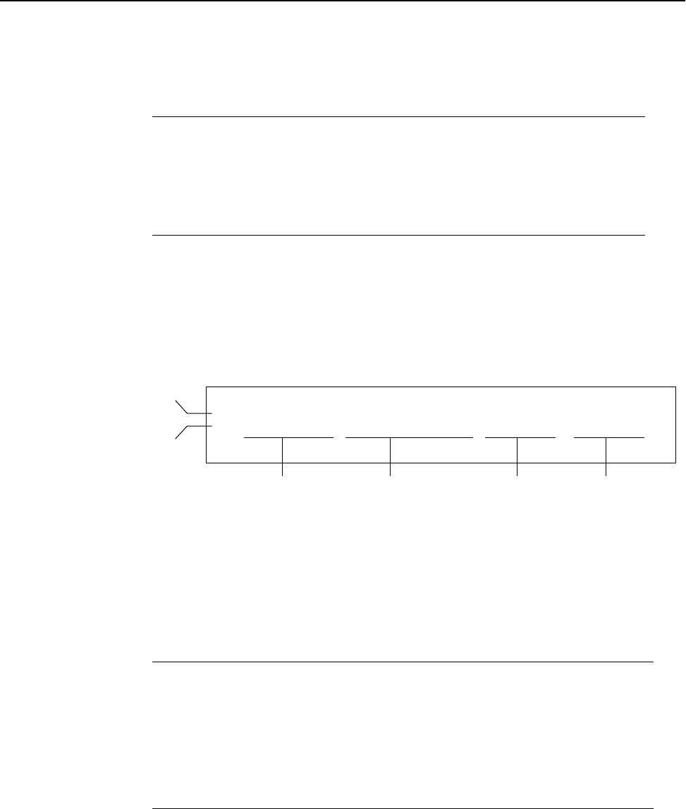
shown below.
Link Statistics
Receive Receives only. Processes expected packet data and displays
statistics on RS-232 monitor.
Transmit Transmits only. Sends known packet data to the receiver.
RSSI RSSI (Received Signal Strength Indicator). Unit receives
packets and displays fade margin data on Air LED.
- BER = 0.0E+00, MPC = 0, EnvP = 63, CorrP = 63
| BER = 0.0E+00, MPC = 0, EnvP = 63, CorrP = 63
Bit Error Rate Missed
Packet
Count
Alternating vertical and horizontal lines indicate that data is incoming.
Envelope Power Correlation Power
Previous
Sample
Current
Sample
where
BER Bit Error Rate
MPC Missed Packet Count
EnvP Envelope Power. The power of the received
signal inlcuding noise, measured in dB (0–63)
CorrP Correlation Power. The power of the received
signal, excluding noise, measured in dB (0–63)

Configuration
34 Version 1.0 Rev B - 08/00
RSSI mode is used to measure the fade margin of a system. The receive unit is put into
RSSI mode and its AIR LED indicates the fade margin according to the following table:
To set the operating mode
1. From the Main Menu, select RF Station Configuration. The RF Station
Configuration window is displayed.
2. Select Operating Mode.
3. Select the desired mode: Normal Mode, Transmit Mode, Receive Mode, or RSSI
Mode.
4. Press Enter.
Note: The operating mode can also be set with the MODE button on the back of the
Hopper Plus. See Setting Operating Mode with the MODE Button, page 68 for more
information.
AIR LED Color Signal Strength
Green Reliable signal - greater than 15 dB fade margin
Orange Marginal signal - between 11 and 15 dB fade margin
Red Poor signal - less than 10 dB fade margin
Blank No signal at all
RF Station Configuration
Operating Mode -> Normal Mode
RF Transmit Status unblocked
Link Monitor Period (0=OFF, 1-10000) 0
Test Mode Timer Minutes (1-1000) 5
Base Station Only Parameters
Maximum Remote Distance 5 Km
Link Monitor Remote Station Rank 1
Remote Station Only Parameters
Throttle Enable off
Throttle Level (1-50) 1

RF Station Configuration
Version 1.0 Rev B - 08/00 35
Setting the RF Transmit Status
This setting blocks a unit from carrying traffic.
To set RF transmit status
1. From the Main Menu, select RF Station Configuration. The RF Station
Configuration window is displayed.
2. Select RF Transmit Status.
3. Select a setting.
4. Press Enter.
unblocked Transmits and receives. This is the default setting.
blocked Receives only
RF Station Configuration
Operating Mode Normal Mode
RF Transmit Status -> unblocked
Link Monitor Period (0=OFF, 1-10000) 0
Test Mode Timer Minutes (1-1000) 5
Base Station Only Parameters
Maximum Remote Distance 5 Km
Link Monitor Remote Station Rank 1
Remote Station Only Parameters
Throttle Enable off
Throttle Level (1-50) 1

Configuration
36 Version 1.0 Rev B - 08/00
Setting the Link Monitor Period
The Link Monitor Period determines the amount of test data that is sent during a link
monitor test. The following table shows how much test data is sent during the link monitor
test.
To set Link Monitor Period
1. From the Main Menu, select RF Station Configuration. The RF Station
Configuration window is displayed.
2. Select Link Monitor Period.
3. Type the time value in minutes (0=OFF, 1-1000)
4. Press Enter.
Monitor
Setting Test data (%) Message data (%) Notes
0 0 100 link monitor disabled
1 50 50 maximum test data
2 33.3 66.6
325 75
. . . . . . . . .
10000 0.01 99.99 minimum test data
RF Station Configuration
Operating Mode Normal Mode
RF Transmit Status unblocked
Link Monitor Period (0=OFF, 1-10000) ->10
Test Mode Timer Minutes (1-1000) 5
Base Station Only Parameters
Maximum Remote Distance 5 Km
Link Monitor Remote Station Rank 1
Remote Station Only Parameters
Throttle Enable off
Throttle Level (1-50) 1

RF Station Configuration
Version 1.0 Rev B - 08/00 37
Setting Maximum Remote Distance (Base Station Only)
The Maximum Remote Distance is used to optimize dynamic polling by compensating for
polling delay.
Important: In the base unit, the Maximum Remote Distance should always be set to the
distance between the base and the farthest remote.
To set the maximum remote distance
1. From the Main Menu, select RF Station Configuration. The RF Station
Configuration window is displayed.
2. Select Maximum Remote Distance.
3. Scroll to select the distance of the furthest remote unit.
4. Press Enter.
RF Station Configuration
Operating Mode Normal Mode
RF Transmit Status unblocked
Link Monitor Period (0=OFF, 1-10000) 0
Test Mode Timer (1-1000)mins 5
Base Station Only Parameters
Maximum Remote Distance -> 5 Km
Link Monitor Remote Station Rank 1
Remote Station Only Parameters
Throttle Enable off
Throttle Level (1-50) 1

Configuration
38 Version 1.0 Rev B - 08/00
Setting Link Monitor Remote Station Rank
(Base Station Only)
The Hopper Plus can test the RF link while it carries actual data. Link monitor sends test
data along with the message data (the amount of data sent is determined by the setting of
the Link Monitor Period). See Setting the Link Monitor Period, page 36.) The receiving
unit processes statistics and sends the test data and statistics back to the testing unit. The
testing unit then processes and displays statistics for both directions on the link monitor
display. (See Viewing Link Monitor Statistics, page 66 for information about viewing link
monitor statistics).
Note: It is possible to run the link monitor twice over one link by enabling it on the base
and the remote at the same time. This situation should be avoided as it causes needless
overhead.
You can run the link monitor from the base or any remote. When you run the link monitor
from the base station, you must enter the station rank of the remote whose link you wish to
test (rank represents the number of remotes that the base polls). When you run the link
monitor from a remote, the only link that can be tested is to the base, so the station rank is
not configured.
To set the link monitor rank from the base unit
1. From the Main Menu, select RF Station Configuration. The RF Station
Configuration window is displayed.
2. Select Link Monitor Remote Station Rank.
3. Type the station rank of the remote to test.
RF Station Configuration
Operating Mode Normal Mode
RF Transmit Status unblocked
Link Monitor Period (0-OFF, 1-10000) 0
Test Mode Timer Minutes (1-1000) 5
Base Station Only Parameters
Maximum Remote Distance 5 Km
Link Monitor Remote Station Rank -> 1
Remote Station Only Parameters
Throttle Enable off
Throttle Level (1-50) 1

RF Station Configuration
Version 1.0 Rev B - 08/00 39
4. Press Enter. The RF Station Configuration window is displayed.
5. Select Link Monitor Period.
6. Type in the desired link monitor period (0=OFF, 1-10000).
7. Press Enter.
For information about viewing the statistics, see Viewing Link Monitor Statistics, page 66.
To set the link monitor rank from a remote unit
1. From the Main Menu, select RF Station Configuration. The RF Station
Configuration window is displayed.
2. Select Link Monitor Period.
3. Type in the desired link monitor value (1-10000).
4. Press Enter.
For information about viewing the statistics, see Viewing Link Monitor Statistics, page 66.
RF Station Configuration
Operating Mode Normal Mode
RF Transmit Status unblocked
Link Monitor Period (0-OFF, 1-10000) -> 0
Test Mode Timer Minutes (1-1000) 5
Base Station Only Parameters
Maximum Remote Distance 5 Km
Link Monitor Remote Station Rank 1
Remote Station Only Parameters
Throttle Enable off
Throttle Level (1-50) 1

Configuration
40 Version 1.0 Rev B - 08/00
Setting Throttling (Remote Station Only)
Throttling limits the amount of data that passes though a remote Hopper Plus 120-24 unit.
When throttling is enabled, the amount of data passed is equal to the throttling level times
128 kbps, to a maximum of 6.4 Mbps. Throttling applies to both the down link and up link
traffic, so a setting of 128 kbps means the unit can pass 128 kbps in each direction. When
throttling is disabled, the unit allows up to the maximum available bandwidth. The default
setting is to disable throttling.
To enable throttling
1. From the Main Menu, select RF Station Configuration. The RF Station
Configuration window is displayed.
2. Select Throttle Enable.
3. Scroll to select on.
4. Press Enter.
RF Station Configuration
Operating Mode Normal Mode
RF Transmit Status unblocked
Link Monitor Period (0=OFF, 1-10000) 0
Test Mode Timer (1-1000)mins 5
Base Station Only Parameters
Maximum Remote Distance 5 Km
Link Monitor Remote Station Rank 1
Remote Station Only Parameters
Throttle Enable -> off
Throttle Level (1-50) 1

Radio Module Configuration
Version 1.0 Rev B - 08/00 41
Radio Module Configuration
Changing the configuration settings of a Hopper Plus while it operates in a system could
disrupt service. To prevent disruptions when the configuration is being changed, the
Hopper Plus stores configuration information in three different states:
To change the current configuration of the radio module
1. Set the Config Test Minutes. See Setting Config Test Minutes, page 48.
2. Make new configuration changes with the Radio Module Configuration menu. These
changes are stored in the New state, but the radio uses the Current state configuration
until it is rebooted with new configuration.
3. Reboot the unit following the steps in Rebooting and Saving RF Configurations, page
53. The unit runs the new configuration, and the old configuration is retained in
FLASH.
4. If the new configuration works as intended, then the changes can be saved to FLASH.
See To save current configuration to FLASH, page 54.
If the new configuration disrupts communications, then the configuration stored in
FLASH is restored after a timeout has elapsed. The unit can be re-configured and
tested until the unit works as intended.
New The intended configuration changes. Temporary.
Current The configuration actually running on the unit. Temporary.
Flash The configuration that was stored last in FLASH memory.
Final configuration is saved to FLASH memory.

Configuration
42 Version 1.0 Rev B - 08/00
Setting the Station Type
Each Hopper Plus 120-24 unit must be defined as a base or a remote unit. In any given
system there is only one base unit, but there can be numerous remote units.
To set the station type
1. From the Main Menu, select Radio Module Configuration. The Radio
Module Configuration window is displayed.
2. Select Station Type.
3. Scroll to select the desired station type (base unit or remote unit).
4. Press Enter.
Radio Module Configuration
New Current Flash
Station Type -> Remote Unit Remote Unit Remote Unit
Station Rank (1-1000) 1 1 1
Center Frequency 2.4400 GHz 2.4400 GHz 2.4400 GHz
Security Password 1 (Hex) 1 1 1
Security Password 2 (Hex) 10 10 10
Security Password 3 (Hex) 100 100 100
Security Password 4 (Hex) 1000 1000 1000
Security Password 5 (Hex) 10000 10000 10000
Scrambling Code (Hex) 0 0 0
Acquisition Code (0-15) 1 1 1
Config Test Minutes (1-120) 30 30 30
Base Station Only Parameters
Repeater Mode off off off
System Symmetry Type Asymmetric Asymmetric Asymmetric
Dynamic Polling Level (1-100) 1
Remote Station Only Parameters
Remote Unit RF Group (0-63) 0 0 0
Reboot New RF configuration Press Enter to Execute
Save Current Config to Flash Press Enter to Execute

Radio Module Configuration
Version 1.0 Rev B - 08/00 43
Setting the Station Rank
For a base station, rank is the number of remotes that the base polls (regardless of the
actual number of remotes in the system). The base station rank should equal the number of
remotes so the base does not waste time polling nonexistent remotes.
For a remote unit, rank is a unique number that identifies the remote to the base station.
The base station polls remote units sequentially from rank 1 to the base unit s station rank,
then repeats the process.
To set the station rank
1. From the Main Menu, select Radio Module Configuration. The Radio Module
Configuration window is displayed.
2. Select Station Rank (1-1000).
3. Type the rank number of the station.
4. Press Enter.
Radio Module Configuration
New Current Flash
Station Type Remote Unit Remote Unit Remote Unit
Station Rank (1-1000) -> 1 1 1
Center Frequency 2.4400 GHz 2.4400 GHz 2.4400 GHz
Security Password 1 (Hex) 1 1 1
Security Password 2 (Hex) 10 10 10
Security Password 3 (Hex) 100 100 100
Security Password 4 (Hex) 1000 1000 1000
Security Password 5 (Hex) 10000 10000 10000
Scrambling Code (Hex) 0 0 0
Acquisition Code (0-15) 1 1 1
Config Test Minutes (1-120) 30 30 30
Base Station Only Parameters
Repeater Mode off off off
System Symmetry Type Asymmetric Asymmetric Asymmetric
Dynamic Polling Level (1-100) 1
Remote Station Only Parameters
Remote Unit RF Group (0-63) 0 0 0
Reboot New RF configuration Press Enter to Execute
Save Current Config to Flash Press Enter to Execute

Configuration
44 Version 1.0 Rev B - 08/00
Setting the Center Frequency
The center frequency defines the channel the unit uses to transmit and receive RF energy.
To ensure communication between units, all units in a system must have the same center
frequency value.
To set the center frequency
1. From the Main Menu, select Radio Module Configuration. The Radio
Module Configuration window is displayed.
2. Select Center Frequency.
3. Scroll to select the RF center frequency to apply to all units in the network.
4. Press Enter. The center frequency is stored in the New state.
Radio Module Configuration
New Current Flash
Station Type Remote Unit Remote Unit Remote Unit
Station Rank (1-1000) 1 1 1
Center Frequency -> 2.4400 GHz 2.4400 GHz 2.4400 GHz
Security Password 1 (Hex) 1 1 1
Security Password 2 (Hex) 10 10 10
Security Password 3 (Hex) 100 100 100
Security Password 4 (Hex) 1000 1000 1000
Security Password 5 (Hex) 10000 10000 10000
Scrambling Code (Hex) 0 0 0
Acquisition Code (0-15) 1 1 1
Config Test Minutes (1-120) 30 30 30
Base Station Only Parameters
Repeater Mode off off off
System Symmetry Type Asymmetric Asymmetric Asymmetric
Dynamic Polling Level (1-100) 1
Remote Station Only Parameters
Remote Unit RF Group (0-63) 0 0 0
Reboot New RF configuration Press Enter to Execute
Save Current Config to Flash Press Enter to Execute
Radio Module Configuration
Version 1.0 Rev B - 08/00 45
Setting Security Passwords
Up to five different passwords can be set for a unit. Only Security Password 1 is required,
the other passwords are optional. The higher the number passwords that are used, the
higher the level of security for the unit. The set of passwords on the remote unit must
match the set of passwords on the base unit. All passwords are exchanged between units,
even when l password are not used. Passwords can be set and modified directly with the
Radio Module Configuration menu.
Note: All units in the same network must have this setting set to the same value.
To set security passwords
1. From the Main Menu, select Radio Module Configuration. The Radio
Module Configuration window is displayed.
2. Select Security Password 1.
3. Enter a password in Hex code.
4. Press Enter. The password is stored in the New state.
Note: Security Passwords 2 to 5 are optional.
5. If you want to use more than one password, select Security Password n.
6. Enter a password in Hex code.
7. Select Reboot New RF configuration.
8. Press Enter. The passwords are put into effect.
Radio Module Configuration
New Current Flash
Station Type Remote Unit Remote Unit Remote Unit
Station Rank (1-1000) 1 1 1
Center Frequency -> 2.4400 GHz 2.4400 GHz 2.4400 GHz
Security Password 1 (Hex) 1 1 1
Security Password 2 (Hex) 10 10 10
Security Password 3 (Hex) 100 100 100
Security Password 4 (Hex) 1000 1000 1000
Security Password 5 (Hex) 10000 10000 10000
Scrambling Code (Hex) 0 0 0
Acquisition Code (0-15) 1 1 1
Config Test Minutes (1-120) 30 30 30
Base Station Only Parameters
Repeater Mode off off off
System Symmetry Type Asymmetric Asymmetric Asymmetric
Dynamic Polling Level (1-100) 1
Remote Station Only Parameters
Remote Unit RF Group (0-63) 0 0 0
Reboot New RF configuration Press Enter to Execute
Save Current Config to Flash Press Enter to Execute
All units in the
same network
must have these
configurations
set the same.

Configuration
46 Version 1.0 Rev B - 08/00
Setting the Scrambling Code
The scrambling code is used to scramble messages so only units with the correct
scrambling code will be able to read messages. The scrambling code can be 0-32 bits long.
Note: All units in the same network must have this setting set to the same value.
To set scrambling codes
1. From the Main Menu, select Radio Module Configuration. The Radio
Module Configuration window appears.
2. Select Scrambling Code.
3. Type the code.
4. Press Enter.
Radio Module Configuration
New Current Flash
Station Type Remote Unit Remote Unit Remote Unit
Station Rank (1-1000) 1 1 1
Center Frequency 2.4400 GHz 2.4400 GHz 2.4400 GHz
Security Password 1 (Hex) 1 1 1
Security Password 2 (Hex) 10 10 10
Security Password 3 (Hex) 100 100 100
Security Password 4 (Hex) 1000 1000 1000
Security Password 5 (Hex) 10000 10000 10000
Scrambling Code (Hex) -> 0 0 0
Acquisition Code (0-15) 1 1 1
Config Test Minutes (1-120) 30 30 30
Base Station Only Parameters
Repeater Mode off off off
System Symmetry Type Asymmetric Asymmetric Asymmetric
Dynamic Polling Level (1-100) 1
Remote Station Only Parameters
Remote Unit RF Group (0-63) 0 0 0
Reboot New RF configuration Press Enter to Execute
Save Current Config to Flash Press Enter to Execute

Radio Module Configuration
Version 1.0 Rev B - 08/00 47
Setting the Acquisition Code
The acquisition code ensures that the receiver does not process any signals not intended
for that receiver. The receiver processes only signals with the correct acquisition code.
Note: All units in the same network must have this setting set to the same value.
To set the acquisition code
1. From the Main Menu, select Radio Module Configuration. The Radio
Module Configuration window is displayed.
2. Select Acquisition Code.
3. Type the Acquisition code (0-15).
4. Press Enter.
Radio Module Configuration
New Current Flash
Station Type Remote Unit Remote Unit Remote Unit
Station Rank (1-1000) 1 1 1
Center Frequency 2.4400 GHz 2.4400 GHz 2.4400 GHz
Security Password 1 (Hex) 1 1 1
Security Password 2 (Hex) 10 10 10
Security Password 3 (Hex) 100 100 100
Security Password 4 (Hex) 1000 1000 1000
Security Password 5 (Hex) 10000 10000 10000
Scrambling Code (Hex) 0 0 0
Acquisition Code (0-15) -> 0 0 0
Config Test Minutes (1-120) 30 30 30
Base Station Only Parameters
Repeater Mode off off off
System Symmetry Type Asymmetric Asymmetric Asymmetric
Dynamic Polling Level (1-100) 1
Remote Station Only Parameters
Remote Unit RF Group (0-63) 0 0 0
Reboot New RF configuration Press Enter to Execute
Save Current Config to Flash Press Enter to Execute

Configuration
48 Version 1.0 Rev B - 08/00
Setting Config Test Minutes
Since there is a chance that RF configuration changes will disrupt communications, each
unit returns to its pre-configuration state after a timeout (unless the changes are saved to
FLASH before the timeout). This timeout is set with the Config Test Minutes parameter,
which can be set from 1 to 120 minutes.
When testing, the configuration test timeout value should be set before any other radio
module changes are made, so that the correct value is used if other changes cause the unit
to lock up. If you set the timeout too low, then you may not have time to save the changes
to FLASH. If you set it too high, then you will have to wait a long time for the unit to
reboot after a change that disrupts service.
Note: All units in the same network must have this setting set to the same value.
To set the test timeout
1. From the Main Menu, select Radio Module Configuration. The Radio
Module Configuration window is displayed.
2. Select Config Test Minutes.
3. Type the test minutes value (1-120).
4. Press Enter.
5. Select Reboot New RF configuration.
6. Press Enter. The unit reboots with the temporary test timeout period in effect.
7. To move the setting to FLASH see Rebooting and Saving RF Configurations, page 53.
Radio Module Configuration
New Current Flash
Station Type Remote Unit Remote Unit Remote Unit
Station Rank (1-1000) 1 1 1
Center Frequency 2.4400 GHz 2.4400 GHz 2.4400 GHz
Security Password 1 (Hex) 1 1 1
Security Password 2 (Hex) 10 10 10
Security Password 3 (Hex) 100 100 100
Security Password 4 (Hex) 1000 1000 1000
Security Password 5 (Hex) 10000 10000 10000
Scrambling Code (Hex) 0 0 0
Acquisition Code (0-15) 0 0 0
Config Test Minutes (1-120) -> 30 30 30
Base Station Only Parameters
Repeater Mode off off off
System Symmetry Type Asymmetric Asymmetric Asymmetric
Dynamic Polling Level (1-100) 1
Remote Station Only Parameters
Remote Unit RF Group (0-63) 0 0 0
Reboot New RF configuration Press Enter to Execute
Save Current Config to Flash Press Enter to Execute

Radio Module Configuration
Version 1.0 Rev B - 08/00 49
Setting Repeater Mode (Base Station Only)
When a base unit has repeater mode enabled, it re-transmits messages to all remotes in the
same RF group. When repeater mode is disabled, remote-to-remote traffic is allowed if
radio communication is possible and remotes are in the same non-zero RF group.
To set the repeater mode
1. From the Main Menu, select Radio Module Configuration. The Radio Module
Configuration window is displayed.
2. Select Repeater Mode.
3. In the Repeater Mode entry field, scroll to select the desired setting based on the
following table.
4. Press Enter.
off Base unit does not re-transmit messages. This is the default
setting.
on Base unit re-transmits messages received from one remote to
other remotes in the same RF group.
Radio Module Configuration
New Current Flash
Station Type Remote Unit Remote Unit Remote Unit
Station Rank (1-1000) 1 1 1
Center Frequency 2.4400 GHz 2.4400 GHz 2.4400 GHz
Security Password 1 (Hex) 1 1 1
Security Password 2 (Hex) 10 10 10
Security Password 3 (Hex) 100 100 100
Security Password 4 (Hex) 1000 1000 1000
Security Password 5 (Hex) 10000 10000 10000
Scrambling Code (Hex) 0 0 0
Acquisition Code (0-15) 0 0 0
Config Test Minutes (1-120) 30 30 30
Base Station Only Parameters
Repeater Mode -> off off off
System Symmetry Type Asymmetric Asymmetric Asymmetric
Dynamic Polling Level (1-100) 1
Remote Station Only Parameters
Remote Unit RF Group (0-63) 0 0 0
Reboot New RF configuration Press Enter to Execute
Save Current Config to Flash Press Enter to Execute

Configuration
50 Version 1.0 Rev B - 08/00
Setting System Symmetry Type (Base Station Only)
System symmetry type defines the amount of priority the base unit has when polling the
remotes. The default setting "asymmetric" gives the base unit a time slot after each remote
is polled—an asymmetric system is appropriate when the base is the access point to a large
network.The "symmetric" setting limits the base unit to one time slot for every polling
cycle; a symmetric system is more efficient when the base has data passing requirements
that are similar to the remotes.
To set system symmetry type
1. From the Main Menu, select Radio Module Configuration. The Radio
Module Configuration window is displayed.
2. Select System Symmetry Type.
3. Scroll to the desired setting as follows.
4. Press Enter.
asymmetric Base unit higher priority than remotes: the base unit has
one time slot after every remote time slot. This is the default
setting.
symmetric Base unit the same priority as every remote: the base unit
has one time slot for every polling cycle.
Radio Module Configuration
New Current Flash
Station Type Remote Unit Remote Unit Remote Unit
Station Rank (1-1000) 1 1 1
Center Frequency 2.4400 GHz 2.4400 GHz 2.4400 GHz
Security Password 1 (Hex) 1 1 1
Security Password 2 (Hex) 10 10 10
Security Password 3 (Hex) 100 100 100
Security Password 4 (Hex) 1000 1000 1000
Security Password 5 (Hex) 10000 10000 10000
Scrambling Code (Hex) 0 0 0
Acquisition Code (0-15) 0 0 0
Config Test Minutes (1-120) 30 30 30
Base Station Only Parameters
Repeater Mode off off off
System Symmetry Type -> Asymmetric Asymmetric Asymmetric
Dynamic Polling Level (1-100) 1
Remote Station Only Parameters
Remote Unit RF Group (0-63) 0 0 0
Reboot New RF configuration Press Enter to Execute
Save Current Config to Flash Press Enter to Execute

Radio Module Configuration
Version 1.0 Rev B - 08/00 51
Setting Dynamic Polling Level (Base Station Only)
The Hopper Plus uses dynamic polling to reduce overhead caused by idle remote units.
Every remote unit is polled by the base, and idle units are ignored for the number of
polling rounds entered in the Dynamic Polling Level field.
Dynamic Polling is most effective in very large systems, where polling delay can become
significant.
Important: Polling level is set only for the base unit.
To set the dynamic polling level
1. From the Main Menu, select RF Station Configuration. The RF Station
Configuration window is displayed..
1. Select Dynamic Polling Level.
2. Type the desired polling level (1-60).
3. Press Enter.
Radio Module Configuration
New Current Flash
Station Type Remote Unit Remote Unit Remote Unit
Station Rank (1-1000) 1 1 1
Center Frequency 2.4400 GHz 2.4400 GHz 2.4400 GHz
Security Password 1 (Hex) 1 1 1
Security Password 2 (Hex) 10 10 10
Security Password 3 (Hex) 100 100 100
Security Password 4 (Hex) 1000 1000 1000
Security Password 5 (Hex) 10000 10000 10000
Scrambling Code (Hex) 0 0 0
Acquisition Code (0-15) 0 0 0
Config Test Minutes (1-120) 30 30 30
Base Station Only Parameters
Repeater Mode off off off
System Symmetry Type -> Asymmetric Asymmetric Asymmetric
Dynamic Polling Level (1-100) 1
Remote Station Only Parameters
Remote Unit RF Group (0-63) 0 0 0
Reboot New RF configuration Press Enter to Execute
Save Current Config to Flash Press Enter to Execute

Configuration
52 Version 1.0 Rev B - 08/00
Setting Remote Unit RF Group
Remote unit RF group controls how remote units communicate with each other. Only
remote units in the same non-zero RF group can communicate directly with each other. A
remote with a zero RF group can only communicate with the base unit.
To set remote unit RF group
1. From the Main Menu, select RF Module Configuration. The Radio Module
Configuration window is displayed.
2. Select Remote Unit RF Group.
3. In the Remote Unit RF Group entry field, type the RF group number, using the
following table as a guide.
4. Press Enter.
RF Group Remote Characteristics
0Closed: remote will only transmit to and receive from the base unit.
1-63 Open: remote will transmit to and receive from the base and all
remotes with the same RF group number.
Radio Module Configuration
New Current Flash
Station Type Remote Unit Remote Unit Remote Unit
Station Rank (1-1000) 1 1 1
Center Frequency 2.4400 GHz 2.4400 GHz 2.4400 GHz
Security Password 1 (Hex) 1 1 1
Security Password 2 (Hex) 10 10 10
Security Password 3 (Hex) 100 100 100
Security Password 4 (Hex) 1000 1000 1000
Security Password 5 (Hex) 10000 10000 10000
Scrambling Code (Hex) 0 0 0
Acquisition Code (0-15) 1 1 1
Config Test Minutes (1-120) 30 30 30
Base Station Only Parameters
Repeater Mode off off off
System Symmetry Type Asymmetric Asymmetric Asymmetric
Dynamic Polling Level (1-100) 1
Remote Station Only Parameters
Remote Unit RF Group (0-63) -> 0 0 0
Reboot New RF configuration Press Enter to Execute
Save Current Config to Flash Press Enter to Execute

Radio Module Configuration
Version 1.0 Rev B - 08/00 53
Rebooting and Saving RF Configurations
A reboot is required for temporary changes to the RF configuration to take effect. If the
changes are valid, they can be saved "permanently" in the FLASH memory. If the changes
are not valid, then the old configuration is restored after a programmable time-out.
To reboot new RF configuration
1. From the Main Menu, select Radio Module Configuration. The Radio
Module Configuration window is displayed.
2. Select Reboot New RF Configuration.
3. Press Enter. The Hopper Plus 120-24 reboots with the new temporary RF
configuration. The old configuration is remains stored in FLASH memory. If the RF
configuration is valid and the unit operates as intended, you can login again, access
the Main Menu, Radio Module Configuration, Save Current Config to
Flash to save changes to FLASH memory.
Radio Module Configuration
New Current Flash
Station Type Remote Unit Remote Unit Remote Unit
Station Rank (1-1000) 1 1 1
Center Frequency 2.4400 GHz 2.4400 GHz 2.4400 GHz
Security Password 1 (Hex) 1 1 1
Security Password 2 (Hex) 10 10 10
Security Password 3 (Hex) 100 100 100
Security Password 4 (Hex) 1000 1000 1000
Security Password 5 (Hex) 10000 10000 10000
Scrambling Code (Hex) 0 0 0
Acquisition Code (0-15) 1 1 1
Config Test Minutes (1-120) 30 30 30
Base Station Only Parameters
Repeater Mode off off off
System Symmetry Type Asymmetric Asymmetric Asymmetric
Dynamic Polling Level (1-100) 1
Remote Station Only Parameters
Remote Unit RF Group (0-63) 0 0 0
Reboot New RF configuration -> Press Enter to Execute
Save Current Config to Flash Press Enter to Execute

Configuration
54 Version 1.0 Rev B - 08/00
To save current configuration to FLASH
1. From the Main Menu, select Radio Module Configuration. The Radio
Module Configuration window is displayed.
2. Select Save Current Config to Flash.
3. Press Enter. The current configuration is saved to FLASH. No reboot is required.
Radio Module Configuration
New Current Flash
Station Type Remote Unit Remote Unit Remote Unit
Station Rank (1-1000) 1 1 1
Center Frequency 2.4400 GHz 2.4400 GHz 2.4400 GHz
Security Password 1 (Hex) 1 1 1
Security Password 2 (Hex) 10 10 10
Security Password 3 (Hex) 100 100 100
Security Password 4 (Hex) 1000 1000 1000
Security Password 5 (Hex) 10000 10000 10000
Scrambling Code (Hex) 0 0 0
Acquisition Code (0-15) 1 1 1
Config Test Minutes (1-120) 30 30 30
Base Station Only Parameters
Repeater Mode off off off
System Symmetry Type Asymmetric Asymmetric Asymmetric
Dynamic Polling Level (1-100) 1
Remote Station Only Parameters
Remote Unit RF Group (0-63) 0 0 0
Reboot New RF configuration Press Enter to Execute
Save Current Config to Flash -> Press Enter to Execute

RF/Ethernet Statistics
Version 1.0 Rev B - 08/00 55
RF/Ethernet Statistics
Ethernet and RF statistics can be viewed for troubleshooting and monitoring link
performance. Ethernet and RF statistics are cumulative and increment until reset. The
window is view only. See Resetting the RF/Ethernet Statistics, page 64 for information
about resetting RF/Ethernet statistics.
Viewing RF/Ethernet Statistics
To view RF and Ethernet statistics
1. From the Main Menu, select RF/Ethernet Statistics. The RF/Ethernet
Statistics window is displayed.
RF/Ethernet Statistics
Ethernet Receive Statistics Ethernet Transmit Statistics
Total Packets Received 0 Total Packets Transmitted 0
Packets For Local Host 0 Packets From Local Host 0
Receive Errors 0 Packets Dropped 0
Packets Dropped 0
Packets Discarded 0
RF Receive Statistics RF Transmit Statistics
Total Packets Received 0 Total Packets Transmitted 0
Packets For Local Host 0 Frames From Local Host 0
Packets Dropped 0 Packets Dropped 0
Packets Discarded 0
RF Super Frame Rx Statistics RF Super Frame Tx Statistics
Super Frames Received 0 Super Frames Transmitted 0
Receive Overrun Errors 0
Frame Control Word Errors 0
Header Checksum Errors 0 Throughput Statistics
Packet Control Word Errors 0 Ethernet-to-RF Throughput 0
Super Frame Length Errors 0 RF-to-Ethernet Throughput 0

Configuration
56 Version 1.0 Rev B - 08/00
.
where
Ethernet Receive
Total Packets
Received
The number of Ethernet packets from the 10/100
Base-T connection.
Packets For Local
Host
The number of Ethernet packets received from the
10/100 Base-T connection which were destined for
the Hopper Plus 120-24 unit’s TCP/IP stack.
Receive Errors The number of Ethernet packets received with
errors, for example, runt (smaller than 64 bytes),
jabber (larger than 1518 bytes), or overflow error.
Packets Dropped The number of Ethernet packets dropped because
the wireless link is at capacity.
Packets Discarded The number of Ethernet packets discarded as the
result of filtering.
RF Receive
Total Packets
Received
The number of Ethernet packets received over RF.
Packets For Local
Host
The number of Ethernet packets received over RF
and destined for the local host.
Packets Dropped The number of Ethernet packets dropped because
the wireless link is at capacity.
Packets Discarded The number of Ethernet packets discarded as the
result of filtering.
RF Super Frame Rx
Super Frames
Received
The number of super frames received.
Receive Overrun
Errors
The number of errors caused by receive buffer
overrun.
Frame Control Word
Errors
The number of errors caused by frame control word
problems.
Header Checksum
Word Errors
The number of errors caused by receiving an
invalid header checksum.
Packet Control
Word Errors
The number of errors caused by packet control
word problems.
Super Frame Length
Errors
The number of errors caused by receiving an
invalid super frame length.

RF/Ethernet Statistics
Version 1.0 Rev B - 08/00 57
Ethernet Transmit
Total Packets
Transmitted
The number of Ethernet packets transmitted onto
the 10/100 Base-T connection.
Packets From Local
Host
The number of Ethernet packets transmitted onto
the 10/100 Base-T connection which originated
from the Hopper Plus 120-24 unit’s TCP/IP stack.
Packets Dropped The number of Ethernet packets not transmitted
due to some error, for example, unable to transmit
within 15 retries, or underflow error.
RF Transmit
Total Packets
Transmitted
The number of Ethernet packets transmitted over
RF.
Frames From Local
Host
The number of Ethernet packets transmitted to RF
from the local host.
Packets Dropped The number of packets dropped because of RF
problems.
RF S. F. Tx
Super Frames
Transmitted
The number of super frames transmitted.
Throughput
Ethernet-to-RF
Throughput
Current data rate measured from wire to air,
resolution = 1 second.
RF-to-Ethernet
Throughput
Current data rate measured from air to wire,
resolution = 1 second.
where

Configuration
58 Version 1.0 Rev B - 08/00
System Security
You can control access to the Hopper Plus 120-24 unit with the System Security menu.
Setting Community Names
Community names are used to control SNMP access to the Hopper Plus. Community
Name 1 has read only access, and Community Name 2 has read and write access. Any
SNMP manager can access and configure any Hopper Plus unit on the network as long as
the unit has the correct community names and Ethernet access is enabled (see Setting
Remote Access, page 60).
Warning: Default community names are presented in all Installation and Configuration
guides distributed by Wi-LAN. It is the responsibility of the customer to ensure that
default community names are changed to unique names at installation. Record all
community name changes.
To set community names
1. From the Main Menu, select System Security. The System Security window is
displayed.
2. Select SNMP Community Name 1.
3. Type in new name.
4. Press Enter. The new name appears in the entry field.
5. Select SNMP Community Name 2.
6. Type in new name.
7. Press Enter. The new name appears in the entry field.
Community name Privileges Default value
SNMP Community Name 1 Read public
SNMP Community Name 2 Read and Write netman
System Security
SNMP Community Name 1 -> public
SNMP Community Name 2 netman
Change User Password Press Enter to change password
Confirm User Password Press Enter to confirm password
Change Supervisor Password Press Enter to change password
Confirm Supervisor Password Press Enter to confirm password
Ethernet Access to Local Host on
Wireless Access to Local Host on
Auto Logout Minutes (1-120) 10

System Security
Version 1.0 Rev B - 08/00 59
Setting Login Passwords
You can control access to the configuration menus by setting passwords for the user and
supervisor logins. The user login has read-only access, while the supervisor login can
modify configuration settings. The default passwords match the login names.
Warning: Default passwords are listed in all Installation and Configuration guides
distributed by Wi-LAN. It is the responsibility of the customer to ensure that default
passwords are changed to unique passwords during installation. Record all password
changes.
Note: When you restore factory configurations, the login passwords revert to the defaults.
To set user password
1. From the Main Menu, select System Security. The System Security window is
displayed.
2. Select Change User Password.
3. Type the new password.
4. Press Enter.
5. Select Confirm User Password entry field.
6. Re-type the password from step 3.
7. Press Enter. The change is saved when appears beside the confirmation
field.
To set supervisor password
1. From the Main Menu, select System Security. The System Security window
appears (see above).
2. Select Change Supervisor Password.
3. Type the new password.
4. Press Enter.
5. Select Confirm Supervisor Password entry field.
6. Re-type the password from step 3.
System Security
SNMP Community Name 1 public
SNMP Community Name 2 netman
Change User Password -> Press Enter to change password
Confirm User Password Press Enter to confirm password
Change Supervisor Password Press Enter to change password
Confirm Supervisor Password Press Enter to confirm password
Ethernet Access to Local Host on
Wireless Access to Local Host on
Auto Logout Minutes (1-120) 10
Success

Configuration
60 Version 1.0 Rev B - 08/00
7. Press Enter. The change is saved when appears beside the confirmation
field.
Setting Remote Access
The Hopper Plus can be accessed and configured via the Ethernet and over the RF link.
The default setting is to allow both forms of remote access, but they can be disabled if
required (as a security measure, for example).
To set Ethernet and wireless access
1. From the Main Menu, select System Security. The System Security window is
displayed.
2. Select Ethernet Access to Local Host.
3. In the Ethernet Access to Local Host field, select the desired setting.
4. Press Enter.
5. Select Wireless Access to Local Host.
6. Select the desired setting.
7. Press Enter.
on Enable access to the unit via the Ethernet.
off Disable access to the unit via the Ethernet.
on Enable access to the unit via the air.
off Disable access to the unit via the air.
Success
System Security
SNMP Community Name 1 public
SNMP Community Name 2 netman
Change User Password Press Enter to change password
Confirm User Password Press Enter to confirm password
Change Supervisor Password Press Enter to change password
Confirm Supervisor Password Press Enter to confirm password
Ethernet Access to Local Host -> on
Wireless Access to Local Host on
Auto Logout Minutes (1-120) 10

System Security
Version 1.0 Rev B - 08/00 61
Setting the Automatic Timeout
You can specify the maximum time the system can remain idle before the configuration
menus close and the Login menu reappears. This ensures that the configuration menus
close if a user forgets to exit.
Note: When the menus automatically timeout, the system appears frozen. Press Enter
to view the Login window, where you can login to the menus.
To set the automatic timeout period
1. From the Main Menu, select System Security. The System Security window is
displayed.
2. Select Auto Logout Minutes.
3. Type the maximum idle time period in minutes that can pass before the configuration
menus close.
4. Press Enter. The new value appears in the entry field.
System Security
SNMP Community Name 1 public
SNMP Community Name 2 netman
Change User Password Press Enter to change password
Confirm User Password Press Enter to confirm password
Change Supervisor Password Press Enter to change password
Confirm Supervisor Password Press Enter to confirm password
Ethernet Access to Local Host on
Wireless Access to Local Host on
Auto Logout Minutes (1-120) -> 10

Configuration
62 Version 1.0 Rev B - 08/00
System Commands
System image files contain the software that runs the unit. When you first power up the
Hopper Plus unit, it runs from the factory-image. With the System Commands menu you
can choose the image file that a unit uses to power up, and the image file that a unit uses to
reboot.
Note: As new images are developed, Wi-LAN plans to place the images on their web site
so that you can download them to the unit.
Setting Default System Image
The default image is the image file used at power up. If you have more than one image
saved on a unit, you can choose the default power up file.
To set the default image
1. From the Main Menu, select System Commands. The System Commands window
is displayed.
2. Select Default System Image.
3. Scroll to select the image to use as the default.
4. Press Enter. The new image file appears in the field. This image will be used each
time the Hopper Plus is powered up.
System Commands
Default System Image -> FACTORY-IMAGE
Reboot a System Image FACTORY-IMAGE
Reboot Current Image Press Enter to Execute
Restore Factory Config and Reboot Press Enter to Execute
Reset Radio Statistics Press Enter to Execute
Reset Ethernet Statistics Press Enter to Execute

System Commands
Version 1.0 Rev B - 08/00 63
Setting the Reboot System Image
To set the reboot image
1. From the Main Menu, select System Commands. The System Commands window
is displayed.
2. Select Reboot a System Image.
3. Scroll to select the image to use when rebooting.
4. Press Enter. The new image file appears in the field. This image will be used when the
Hopper Plus is rebooted.
Rebooting the Current Image
The Reboot Current Image command must be used when the IP address is changed. See
Setting the Internet IP Address and Subnet Mask, page 26.
To reboot the current image
1. From the Main Menu, select System Commands. The System Commands window
is displayed.
2. Select Reboot Current Image.
3. Press Enter. The Hopper Plus reboots using the current image.
You must log in again to make further changes.
System Commands
Default System Image FACTORY-IMAGE
Reboot a System Image -> FACTORY-IMAGE
Reboot Current Image Press Enter to Execute
Restore Factory Config and Reboot Press Enter to Execute
Reset Radio Statistics Press Enter to Execute
Reset Ethernet Statistics Press Enter to Execute
System Commands
Default System Image FACTORY-IMAGE
Reboot a System Image FACTORY-IMAGE
Reboot Current Image -> Press Enter to Execute
Restore Factory Config and Reboot Press Enter to Execute
Reset Radio Statistics Press Enter to Execute
Reset Ethernet Statistics Press Enter to Execute

Configuration
64 Version 1.0 Rev B - 08/00
Restoring Configurations
After making configuration changes you can return the unit to its original state by
restoring factory configuration settings. This command can be used put the unit into a
known state to aid troubleshooting, or to ensure that company configurations are removed
when decommissioning the unit.
To restore the factory configuration
1. From the Main Menu, select System Commands. The System Commands window
is displayed.
2. Select Restore Factory Configuration and Reboot.
3. Press Enter. The factory configuration settings are restored.
Warning: When you restore factory configurations, the login passwords are
automatically set to default values.
You must log in again to make further changes.
Resetting the RF/Ethernet Statistics
The statistics displayed in the RF/Ethernet Statistics window are cumulative, but can be
reset to track events and for troubleshooting. For example, a suspected RF problem can be
diagnosed by resetting the radio statistics and simulating the situation suspected of
causing the problem.
System Commands
Default System Image FACTORY-IMAGE
Reboot a System Image FACTORY-IMAGE
Reboot Current Image Press Enter to Execute
Restore Factory Config and Reboot -> Press Enter to Execute
Reset Radio Statistics Press Enter to Execute
Reset Ethernet Statistics Press Enter to Execute
System Commands
Version 1.0 Rev B - 08/00 65
To reset radio statistics
1. From the Main Menu, select System Commands.The System Commands window
is displayed.
2. Select Reset Radio Statistics.
3. Press Enter. The radio statistics in the RF/Ethernet Statistics window are reset to 0
when appears beside the enter field.
See Viewing RF/Ethernet Statistics, page 55.
To reset Ethernet statistics
1. From the Main Menu, select System Commands. The System Commands window
is displayed.
2. Select Reset Ethernet Statistics.
3. Press Enter. The Ethernet statistics in the RF/Ethernet Statistics window are reset to 0
when appears beside the enter field.
See Viewing RF/Ethernet Statistics, page 55.
System Commands
Default System Image FACTORY-IMAGE
Reboot a System Image FACTORY-IMAGE
Reboot Current Image Press Enter to Execute
Restore Factory Config and Reboot Press Enter to Execute
Reset Radio Statistics -> Press Enter to Execute
Reset Ethernet Statistics Press Enter to Execute
Success
System Commands
Default System Image FACTORY-IMAGE
Reboot a System Image FACTORY-IMAGE
Reboot Current Image Press Enter to Execute
Restore Factory Config and Reboot Press Enter to Execute
Reset Radio Statistics Press Enter to Execute
Reset Ethernet Statistics -> Press Enter to Execute
Success

Configuration
66 Version 1.0 Rev B - 08/00
Link Monitor Display
Viewing Link Monitor Statistics
Link performance statistics such as power and bit error rate can be viewed while the link
monitor is running. Statistics are only available on the unit running the link monitor. The
window is view only.
To view link monitor statistics
1. From the Main Menu, select Link Monitor Display. The RF Background Link
Monitor Statistics window is displayed.
where
Link Monitor Rank When viewed on the base unit, the rank of the
remote unit whose link is being tested. When
viewed on the remote unit, this field is zero.
Base to Remote BER The bit error rate from the base to the remote.
Displays “N/A” when the link monitor is not
running.
Remote to Base BER The bit error rate from the remote to the base.
Displays “N/A” when the link monitor is not
running.
Missed Packet Count The number of missed packets.
Base to Remote Env
Power
Envelope power received at the remote.
Base to Remote Corr
Power
Correlation power received at the remote.
Remote to Base Env
Power
Envelope power received at the base.
Remote to Base Corr
Power
Correlation power received at the base.
RF Background Link Monitor Statistics
Link Monitor Rank 0
Base to Remote BER N/A
Remote to Base BER N/A
Missed Packet Count 0
Base to Remote Env Power 0
Base to Remote Corr Power 0
Remote to Base Env Power 0
Remote to Base Corr Power 0

Logout
Version 1.0 Rev B - 08/00 67
Logout
Logging Out
To log out of the Main Menu
1. From the Main Menu, select Logout.
2. Press Enter.
3. Power down the computer.
or
1. Press the Esc key on the keyboard until you reach the wilan command line.
2. At the prompt, type logout.
3. Press Enter.
Enter ESC to return to Main Menu
wilan> logout

Configuration
68 Version 1.0 Rev B - 08/00
Setting Operating Mode with the MODE Button
The operating mode of a unit is usually set with the RF Station Configuration menu (see
Setting the Operating Mode, page 33). However, operating mode can also be set using the
MODE button located on the back panel of the Hopper Plus 120-24. No tools or
equipment are required to use this method, however, a good understanding of the
operating modes and LEDs is required.
The Hopper Plus starts up in Normal operating mode with the MODE LED off.. Three test
modes are available.
You can change the operating mode by pressing the MODE button, as explained below.
Using the MODE Button
To change the operating mode
1. Press the MODE button once and release it quickly. The unit goes into Transmit
mode.
2. Press the MODE button once and the unit goes into Receive mode.
3. Press the MODE button once and the unit goes into RSSI mode.
4. Press the MODE button once and the unit returns to Transmit mode.
5. To return to Normal mode, press the MODE button and hold it down for at least two
seconds. The AIR LED and MODE LED flash orange when the button has been held
long enough.
Note: If you do not manually return the unit to normal mode, the unit automatically
reboots and returns to normal mode when end of the test time period time is reached. The
test time period cannot be set with the mode button—you must use the Main Menu to set
the test mode timer (see Setting Config Test Minutes, page 48).
Mode Function MODE LED
Transmit Transmit only. Sends known packet data to the
receiver.
Red
Receive Receive only. Processes received packet data and
displays statistics on RS-232 monitor.
Green
RSSI Received Signal Strength Indicator. Unit receives
packets and displays fade margin data on AIR LED.
Orange
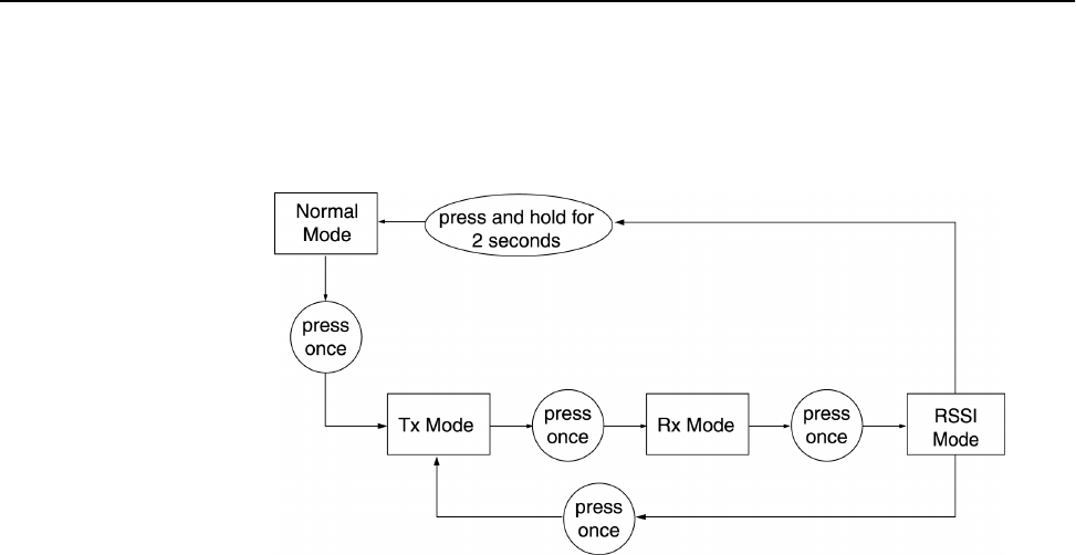
Setting Operating Mode with the MODE Button
Version 1.0 Rev B - 08/00 69
MODE Button Operation
See Setting the Operating Mode, page 33 for more information about operating modes.

Configuration
70 Version 1.0 Rev B - 08/00
Command Line Interface
The Hopper Plus 120-24 has a command line interface you can use to perform basic
commands. The commands are a quick way to perform basic tasks while you remain
logged into the configuration menus.
Using Basic Commands
While you are logged into the configuration menus, you can press the Esc key until you
exit out of the menus to the command line prompt. The wilan> command line prompt
appears.
You can execute all of the Hopper Plus 120-24 commands from this prompt.
The following are some of the commands you can execute at the prompt.
You can contact Wi-LAN customer support for additional information about the command
line interface.
Command Action Example
help show the following command
summary list:
menu cls dir del ping
logout exit quit
wilan>help menu
menu return to the configuration menus wilan>menu
cls clear the terminal screen wilan>cls
dir show a file directory wilan>dir
del delete a file wilan>del sample.txt
ping ping a remote IP address wilan>ping 198.168.200.5
logout log out of the command line
interface
or
terminate a remote telnet session
wilan>logout
exit log out of the command line
interface
or
terminate a remote telnet session
wilan>exit
quit log out of the command line
interface
or
terminate a remote telnet session
wilan>quit
Version 1.0 Rev B - 08/00 71
Appendix A: Planning Your Wireless Link
To ensure an effective and reliable wireless link, you need to perform some preliminary
network planning before you install any hardware.
These steps include:
¥ determining the physical layout of your planned link
¥ planning your antenna and fade margin requirements
¥ configuring your RF link.
Planning the Physical Layout
Before you install the units, you must determine the physical locations for each
component of the Hopper Plus 120-24 wireless system.
When you plan the physical layout, you need to:
¥ measure the physical distance between each pair of units using GPS, a map, or other
distance measurement method
¥ determine antenna mast height requirements and fade margins
¥ determine cable requirements, including routing, between antenna and unit
¥ calculate the fade margin to determine the reliability of your wireless link
¥ determine environmental requirements
Measuring the Physical Distance Between Units
Use a mapping method to determine the distance between sites, and check the radio path
to identify any obstructions in the site path between the two antennas. Due to the high
frequency and low output power permitted in the ISM bands, no obstructions may exist
between two antennas.
Determining Antenna Requirements
If you plan to install the unit indoors, the rubber duck antenna shipped with the unit may
be adequate. The signal from this antenna can penetrate several walls, although metal
obstructions or building features such as elevator shafts can deflect or inhibit radio waves.
Empirical testing is advised in this case because all interiors are unique.
If you plan to install the antennas outdoors you will need to consider
¥ obtaining permission from building owners if you intend to install your antenna on a
rooftop
¥ the height of the antenna required to ensure a radio Line of Sight between two
antennas that define the RF link

Appendix A: Planning Your Wireless Link
72 Version 1.0 Rev B - 08/00
¥ potential wind load and ice loading impact on the antenna
¥ regulatory restrictions, such as height, on antenna mast usage in the identified location
¥ grounding requirements. You must ensure that your antenna is properly grounded for
lightning and installed according to the relevant electrical code for the location.
Determining Cable Requirements
If you are installing the antenna in an outdoor location, you will require 50 ohm coaxial
cable to connect the unit to the antenna. You should minimize the length of the coaxial
cable because the longer the cable is, the greater the cable losses are. You need to know
the required cable lengths before you install the unit.
Note: You should use surge suppressors at the point of cable entry into the building.
Calculating Fade Margins
You can calculate the fade margin of your wireless link after you ve identified the antenna
requirements. The fade margin enables you to predict the reliability of your wireless link.
See Calculating Path Loss on page 78 for more information about fade margins.
Determining Environmental Requirements
Hopper Plus 120-24 units must be located in a weatherproof environment with an ambient
temperature between 0… and 40… Celsius, and humidity from 0 to 95% non-condensing.
Consider the building, heating, and air conditioning required to ensure that the unit
operates within these conditions.
Optimizing the RF Link
Overview
This section explains how to obtain optimal performance from your RF link. Proper path
planning ensures that each end of the RF link receives sufficient signal power to maintain
a desired Bit Error Rate (BER). The effectiveness and reliability of your RF link depends
on the following:
¥ antenna gain, beamwidth, F/B ratio, and cross-polarization discrimination
¥ distance between antennas and obstructions in the RF path
¥ above-ground height of the antennas
¥ length and type of coaxial cable connecting the Hopper Plus 120-24 and the antenna
The above factors will be used to calculate your link budget. The calculation indicates if
your radio link is feasible over a given distance and path and if your RF link meets
regulatory requirements. Link budgets are typically expressed in decibels (dB).

Optimizing the RF Link
Version 1.0 Rev B - 08/00 73
The following dB terms are used in this section:
The following variables are used to calculate the link budget:
Term Description
dB Decibel. A relative measure of power used to specify power
gains and losses. The difference in power P1 and P2
expressed in dB is:
dBd The gain or loss of an antenna reference to a standard dipole.
Gain of a Standard Dipole (dBd) = 2.14 dBi.
dBi The gain or loss of an antenna referenced to an isotropic
(theoretical point source) radiator. This measure is used with
only antennas, as it quantifies gain or loss of a physical
radiator with respect to a theoretical one.
dBm A power measurement referenced to one milliwatt. This is an
absolute measure of power rather than a relative measure
such as a gain or a loss.
Variable Description
System Gain The maximum path loss that the system can support
for usable data transmission.
EIRP (Effective Isotropically
Radiated Power)
The power radiating from an antenna taking into
account the output power from the transmitter,
connector losses, cable losses, and the antenna
gain.
Receiver Sensitivity The minimum signal strength required for usable
performance. Expressed in dBm.
Antenna Gain Gain of the antenna over a dipole (dBd) or
theoretical (dBi).
Propagation Loss The signal loss experienced as it travels through the
air. Expressed in dB.
Cable Loss The signal loss experienced as it passes through the
coaxial cable. Expressed in dB.
Path Loss The total loss from one end of the path to the other.
This includes propagation losses, cable losses, and
any other losses that impact the system
performance.
dB 10 P1
P2
-------
log×=

Appendix A: Planning Your Wireless Link
74 Version 1.0 Rev B - 08/00
Working with System Gain
The system gain of a radio system is the difference between the transmitted power and a
receiver s sensitivity threshold. The system gain of the Hopper Plus 120-24 is:
Formula: System Gain = Transmission Power - Receiver Sensitivity @ 10-6 BER
Variables: Hopper Plus 120-24
Tx Power = 18.5 dBm
Receiver Sensitivity = - 83 dBm (receiver sensitivity @ 10-6 BER)
Calculation: Hopper Plus 120-24
18.5 dBm - (-83) dBm = - 101.5 dB
More info: To ensure reliable communications, the system gain plus all antenna
gains must be greater than the sum of all losses. For a reliable link,
Wi-LAN recommends that the system gain plus all antenna gains be
greater than the sum of all losses by a factor of 15 dB. This factor is
known as the fade margin.

Optimizing the RF Link
Version 1.0 Rev B - 08/00 75
Calculating EIRP (Effective Isotropically Radiated Power)
EIRP is the power radiating from an antenna, taking into account the output power from
the transmitter, the connector and cable losses, and the antenna gain. Unlike the Tx output
power of the devices, EIRP is subject to both antenna gain and cable losses. Many antennas provide a
directional gain, which can increase the effective radiated power. Losses such as cable
losses subtract from this amount. You calculate the EIRP as follows:
Formula: EIRP = Tx Power (dBm) - Cable Losses (dB) - Connector Losses
(dB) + Antenna Gain (dBi)
Note: The FCC regulatory body has set the EIRP limit to +36 dBm for
point-to-multipoint applications per FCC 15.247(b)(3)(i).
For point-to-point applications, the FCC EIRP can be 3 dB higher
than +36 dBm for every 1 dB less Tx power below 30 dBm.
Industry Canada specifies the EIRP limit to ≤+36 dBm as per
RSS-210, 6.2.2(p).
In accordance with ETS 300-328 for 2.4 GHz RLANs, the maximum
EIRP shall not exceed +20 dBm, with a maximum SPD (Spectral
Power Density) not exceeding +10 dBm/MHz. Confirmation is
required with the relevant European national radio communications
local authority for deviations from this specification.

Appendix A: Planning Your Wireless Link
76 Version 1.0 Rev B - 08/00
Optimizing Antenna Gain
To ensure the best range and interference suppression, the external antenna should be
directional, focusing the radio energy in one direction (toward the other end of the link). A
directional antenna focuses the RF energy to the intended station rather than
omni-directionally. This reduces interference from other systems operating at the same
frequency.
Note: In some situations, you may want to use an omni-directional antenna in your
system design. For example, you would use an omni-directional antenna for a base station
with remote sites situated in a 360… path around it.
When you select an antenna, pay particular attention to the gain specification. When you
select an antenna for a remote station, select an antenna with a gain that provides at least
15 dB fade margin.
Antenna gain is specified in either dBi or dBd. When an antenna is specified in dBd, add
2.14 dB to the value to convert it to dBi.
Calculating Propagation Loss
The propagation loss is the attenuation (reduction) in RF signal energy as it travels
through space. In most wireless systems, losses through space are the major contributor to
signal attenuation. When you know the intended installation locations of the base and
remote stations, determine the physical line of sight distance and then calculate the RF
attenuation as follows:
Working with the Fresnel Zone
It is essential that you locate your antennas at maximum above-ground height to ensure
that
1. all ground-based obstructions are cleared from the Line of Sight path
2. the Fresnel Zone is clear of obstructions
Formula: Attenuation (dB) for 2.4 GHz band = 100 dB + 20log(dkm)
where:
dkm = Distance in Kilometers
100 dB = Pathloss Constant in the 2.4 GHz band
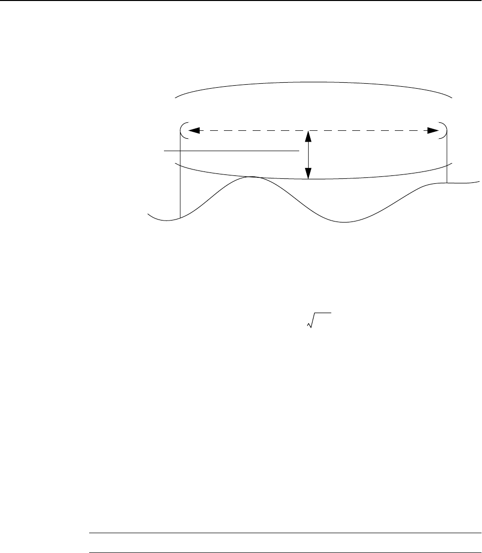
Optimizing the RF Link
Version 1.0 Rev B - 08/00 77
The Fresnel Zone is the expansion of the RF signal radio angles in the vertical plane near
the middle of the RF path. Following diagram shows a Fresnel Zone:
For the 2.4 GHz band, the approximate Fresnel Radius calculated as follows:
Calculating Cable Loss
Cable and connector losses affect the operation of the wireless link and therfore should be
kept to a minimum. The two primary coaxial cable specifications for the Hopper Plus 120-
24 are:
¥ cable must be 50 ohms nominal impedance
¥ cable must be of a low loss type
Generally, cable losses are specified in dB/foot or dB/meter. Following is an example of
cable loss ratings:
Note: When you calculate path loss, you should add 1dB at each end of the link to
compensate for connector losses in addition to the cable loss value.
Formula: Fresnel Radius (meters) =
Cable Type (loss in dB/meter)
Frequency LMR400 LMR600 LDF2-50 LDF4-50A LDF5-50A LDF6-50
2.4 GHz 0.22 0.144 0.190 0.128 0.073 0.053
First Fresnel Zone
Line of Sight
Fresnel Radius
Ground
The maximum
Fresnel Radius
indicates that this
path must be kept
clear of
obstructions.
Fresnel Zone
3.4 dkm
dkm
8.12
----------
2
+

Appendix A: Planning Your Wireless Link
78 Version 1.0 Rev B - 08/00
Calculating Path Loss
Path loss describes the total RF attenuation throughout the system from Tx antenna to Rx
antenna. This includes the losses as the RF signal travels through space plus Tx and Rx
cable loss, and Tx and Rx connector loss. Use the following formula to calculate path loss:
Once you know the path loss, you can compare the value to the system gain value. If the
system gain value is greater than the path loss, the link is feasible. See Working with
System Gain on page 74 for more information about system gain.
Working with the Fade Margin
Total antenna gain
is:
Tx Antenna Gain +
Rx Antenna Gain
The amount by which the system gain plus the total antenna gain exceeds the path loss is
called the fade margin. As calculated, the fade margin is the number of dB that the
received signal strength exceeds the minimum receiver sensitivity. You require some level
of fade margin for any wireless system. The fade margin compensates for RF path fading
due to weather conditions or objects that induce multipath interference.
The Wi-LAN recommended fade margin for the Hopper Plus 120-24 is a minimum of
15 dB. The sum of the cable losses, connector losses, propagation losses, and the 15 dB
required fade margin should be less than the sum of the system gain and antenna gain.
Formula: Path Loss = Tx and Rx Cable Loss + Tx and Rx Connector Loss +
Propagation Loss

Link Budget Example
Version 1.0 Rev B - 08/00 79
Link Budget Example
The values for cable
and connector
losses in this
example are only for
illustration. You will
need to work these
out for your specific
installations.
Putting everything together, you must satisfy the following equations to have a successful
link:
Formulas: System Gain + Antenna Gain ≥ Propagation Loss + Desired Fade
Margin + Cable Losses + Connector Losses
or
Actual Fade Margin ≥ System Gain + Antenna Gain - Propagation
Loss - Cable Losses - Connector Losses
and
Actual Fade Margin ≥ Desired Fade Margin
where:
System Gain = Tx Power - Rx Sensitivity
Antenna Gains = Tx Antenna Gain + Rx Antenna Gain
Cable Losses = Base Cable Losses + Remote Cable Losses
Connector Losses = Base System Connector Losses + Remote
System Connector Losses
Variables: Desired Fade Margin = 15 dB
Tx Power = 18.5 dBm
Rx Sensitivity = -83 dBm
Tx Antenna Gain = 11 dBi
Rx Antenna Gain = 9 dBi
Propagation Loss for
desired range of 1km = 100 + 20 x log(1) = 100 dB
Tx Cable Losses
(2m LMR400) = 2 * 0.22 = 0.44 dB
Rx Cable Losses
(2m LMR 400) = 2 * 0.22 = 0.44 dB
Tx Connector Losses = 1 dB
Rx Connector Losses = 1 dB
Variable
Calculations:
System Gain = 21 - (-79) = 100 dB
Antenna Gains = 11 + 9 = 20 dBi
Cable Losses = 0.44 + 0.44 = 0.88 dB
Connector Losses = 1 + 1 = 2 dB
Actual Fade
Margin
Calculation:
Actual Fade Margin = 100 + 20 - 100 - .88 - 2 = 17.12 dB
Analysis: We have achieved the goal of Actual Fade Margin ≥ 15 dB.

Appendix A: Planning Your Wireless Link
80 Version 1.0 Rev B - 08/00
Antenna Basics
Antennas focus and absorb radio energy in specific directions, depending on their design.
They can be tuned to certain frequency ranges; the Hopper Plus 120-24 antennas must be
tuned to 2.4 - 2.5 GHz.
This section contains some basic information about antenna parameters and how to select
and install antennas for use in your wireless system.
Antenna Parameters
Parameter Description
Gain • Antennas have a gain associated with them, which is a measure
of their ability to amplify signals in their tuned band.
• Antenna gain is achieved by focusing the signal. A higher gain
antenna has more compressed signal.
dBd vs. dBi • Antenna gain must be measured over a known reference and is
often expressed as either dBd or dBi.
• dBd is antenna gain referenced over a half-wave dipole which is
an antenna that has a donut shaped radiation pattern.
• dBi is antenna gain referenced over an isotropic radiator which
is a theoretical antenna that radiates equally in all directions
(e.g. the sun).
• Wi-LAN references antenna gain in dBi. The conversion factor
is:
0 dBd = 2.14 dBi
Beamwidth • The beamwidth of an antenna describes how a signal spreads
out from the antenna, and the range of the reception area.
• Beamwidth is measured between the points on the beam
pattern at which the power density is half of the maximum
power. This is often referred to as the -3 dB points.
• A high gain antenna has a very narrow beamwidth and may be
more difficult to align.
Downtilt or uptilt • Some antennas have either an associated downtilt or an uptilt.
The tilt further focuses the signal downward or upward with
respect to the horizon.
• A tilt may be either electrically built into the antenna or achieved
mechanically with the mounting gear.
• A downtilt or uptilt may be required when there is a significant
deviation between the elevation of the remote site(s) and the
base site.
F/B • Front-to-back ratio.
• Directional antennas focus the signal in a forward path. This is
achieved by directing the signal in one direction that reduces the
signal in the opposite direction.
• A higher gain antenna typically has a greater F/B ratio.

Antenna Basics
Version 1.0 Rev B - 08/00 81
Implementation Considerations
Following are some key items to consider when selecting and installing antennas for your
wireless network:
XPD • Polarity and Cross-Polarization Discrimination (XPD).
• Antennas have an associated polarity, which is the orientation of
the radiating element with respect to earth.
• Antennas are usually described as vertical, horizontal, or
circularly polarized. The polarity of all antennas used in a
system must be the same.
• Cross-Polarization Discrimination specifies the signal isolation
achieved when the receiving element is perpendicular to the
radiating element. This can be advantageous when co-locating
radio systems.
VSWR • Voltage standing wave ratio.
• VSWR is the voltage ratio of minimum to maximum across a
transmission line.
• A VSWR of 2.0:1 or less in an antenna is considered effective.
Most antennas have a VSWR of 1.5:1.
• For example, when using a radio with a 4 watt output with an
antenna VSWR of 1.5:1, the reflected power will be 160
milliwatts.
Item Description
Absorption • Antennas mounted too close to “soft” objects, such as trees,
may experience a reduction in signal strength due to absorption.
• Absorption is most often encountered in applications installed
during the fall or winter months, and the problem does not
become evident until the spring.
Diffraction • Diffraction occurs when a radio signal reflects or bounces off of
a solid object.
• The level of diffraction could lead to connectivity problems if the
remaining signal level is too low.
• Two types of diffraction are shadowing and multipath.
Shadowing • Shadowing is a form of diffraction that is typically caused when
antennas are mounted too close to a structure and they lose a
portion of the signal lobe due to reflection. The receive antenna
is in a shadowed area.
• To minimize shadowing, ensure that there is adequate height
above structures when mounting antenna equipment.
Multipath
Interference
• Multipath is a form of diffraction in which the reflected signal
arrives at the receiver at different times which confuses the
receiver.
• Multipath may be interpreted as interference by the receive
antenna, and can result in bit errors and processing delays.
Parameter Description

Appendix A: Planning Your Wireless Link
82 Version 1.0 Rev B - 08/00
Selecting Antennas
There are several factors to consider when selecting the right antenna for a wireless
application. Following are some initial questions you should ask before selecting an
antenna:
¥ What is the operating frequency range?
¥ Will this be a point-to-point or point-to-multipoint application? Ensure that you
consider if the application will change in the future.
¥ What are the coverage requirements?
¥ How far is the remote site(s)?
¥ What is the gain requirement?
¥ What is the elevation of the remote site(s) with respect to the base station and will
additional downtilt/uptilt be necessary at either the base or remote site to compensate?
¥ Will there be any obstructions in the path?
¥ Will systems be co-located? What polarity will be used?
¥ What are the regional environmental conditions? For example, is there windloading,
salt air, excessive moisture, ice buildup?
¥ What is the antenna lifetime expectation?
¥ What are the site and mounting options?
¥ What are the restrictions in the locale regarding the effective radiated power permitted
from the antenna?
¥ Will antenna appearance be a factor?
Wi-LAN’s Antenna Selection
Following are some antenna selections for the Wi-LAN Hopper Plus 120-24 product:
Antenna Installation Factors
Following are some installation factors you should consider when installing antennas into
your wireless system:
Antenna Type Frequency Gain
Omni 2.4 GHz 6, 9, 12
Dish 2.4 GHz 18, 19, 21, 24, 27
Planar 2.4 GHz 11, 13, 16

Antenna Basics
Version 1.0 Rev B - 08/00 83
Factor Description
Maximizing the
Hopper Plus 120-
24’s Capabilities
• Minimize obstructions in the radio path.
• Line Of Sight (LOS) is crucial for reliability.
• Ensure that equipment is installed correctly.
• Ensure proper grounding, testing, and alignment of antennas.
• Install in environmental conditions that are suitable for the
Hopper Plus 120-24.
• Select proper antennas and cable for the application.
• Ensure sufficient gain for the intended application.
Safety • Proper grounding of antenna apparatus in accordance with
respective Electrical Code(s) is crucial.
• Wi-LAN recommends using a surge arrestor where the antenna
cable enters the building.
• All installations should be completed by a qualified and
competent RF technician.
EIRP • Effective Isotropically Radiated Power (EIRP)
• EIRP is the amount of power that is transmitted to the air from
the antenna.
• EIRP levels depend on the power of the radio transmitter, the
size of the antenna, and the losses incurred in the antenna
cable.
• To remain license-exempt the EIRP must remain under 4 watts
or 36 dBm in Canada and the United States for
point-to-multipoint applications. In Europe, this value is reduced
to 100 mW or 20 dBm.
Note: EIRP = Power out of unit – Power lost in cable + Gain in
power from Antenna
Fade Margin See Calculating Fade Margins on page 72.
LOS • Line of Sight (LOS)
• LOS is a football shaped pattern known as the Fresnel Zone,
which must be kept clear of obstructions. See Working with the
Fresnel Zone on page 76 for more information.
• Visual line of sight must be achieved. When standing at the
antenna position, you must be able to see the remote antenna.

Appendix A: Planning Your Wireless Link
84 Version 1.0 Rev B - 08/00
Minimal Clearance Above Obstructions
For the Hopper Plus 120-24, the absolute minimum clearance above obstructions
requirements are as follows (in meters):
¥ @ 2.4 GHz
Following are some example clearance requirements:
Note: There is also a correction factor added to compensate for curvature of the earth.
This correction factor is not required when the correction value is negligible < 10 km.
Wi-LAN s Link Analysis Spreadsheet takes this variable into account automatically.
Installing Antennas
If your antennas will be located on a support structure, or on top of a tower, you should
have the antenna installed professionally.
Ensure the following:
¥ dipole antennas are oriented vertically (point up).
¥ antennas for the system have the same polarity (vertical, horizontal, or circular).
¥ connectors attaching the coaxial cable to the antenna are properly weatherproofed.
¥ a drip loop is formed at the building entrance, to prevent water flowing down the
coaxial cable and entering the installation building.
¥ the coaxial cable is secured to the supporting structure at one meter intervals. This
prevents wind damage and frost loading problems.
¥ the antenna is firmly attached to the mast to prevent it from falling, yet has some
flexibility so you can move the antenna to fine-tune its position.
¥ the coaxial cable is connected to the antenna and to the antenna port on both sides of
the link (base and remote stations).
¥ the antennas are grounded properly.
Metric
Distance
(km)
2.4 GHz
Clearance
(m)
Imperial
Distance
(miles)
2.4 GHz
Clearance
(ft)
0.5 2.4 0.5 10.0
1 3.4 1 14.3
2 4.9 2 20.5
3 6.0 3 25.7
5 8.0 5 34.9
8 10.6 8 48.3
10 12.3 10 57.6
15 16.6 15 83.8
3.4md
km
×

Antenna Basics
Version 1.0 Rev B - 08/00 85
Fine-tuning Antennas
You can fine-tune the antennas by physically moving the antenna. When the remote
antenna is correctly aligned, the AIR LED is orange, indicating appropriate reception and
acknowledgment of sync tokens from the base station. You can use the Receive and
Transmit operating modes to test the link while adjusting the antennas to minimize BER
and lost packets, and maximize received power. You can use the RSSI operating mode to
maximize RSSI.
Once the antennas are adjusted to maximize performance, secure them properly to the
support structures.
Co-locating Units
When Hopper Plus antennas are located on the same mast, you must take care to ensure
the output power from one radio does not overpower another co-located bridge, even if the
units are operating on different channels. Contact Wi-LAN technical support for antenna
and installation assistance when co-locating units.

Appendix A: Planning Your Wireless Link
86 Version 1.0 Rev B - 08/00
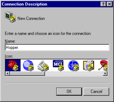
Version 1.0 Rev B - 08/00 87
Appendix B: Using HyperTerminal
The Windows 95/98 operating system includes a terminal emulation program called
HyperTerminal¤. You can use this program to access the Hopper Plus 120-24
configuration menus through the MANAGEMENT port on the front of the unit.
Starting HyperTerminal
To start HyperTerminal
1. In Windows 95 or 98, from the Start menu, select Programs, Accessories,
Communications, HyperTerminal. The Connection Description window is
displayed:
2. Select an icon for the HyperTerminal session and type a connection name.
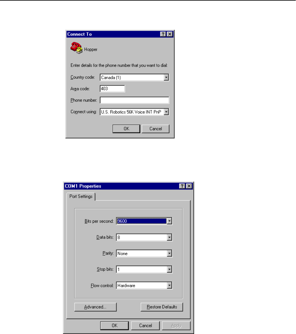
Appendix B: Using HyperTerminal
88 Version 1.0 Rev B - 08/00
3. Click OK. The Connect To window is displayed:
4. In the Connect using field, select the appropriate COM port.
5. Click OK. The COM Properties window is displayed:
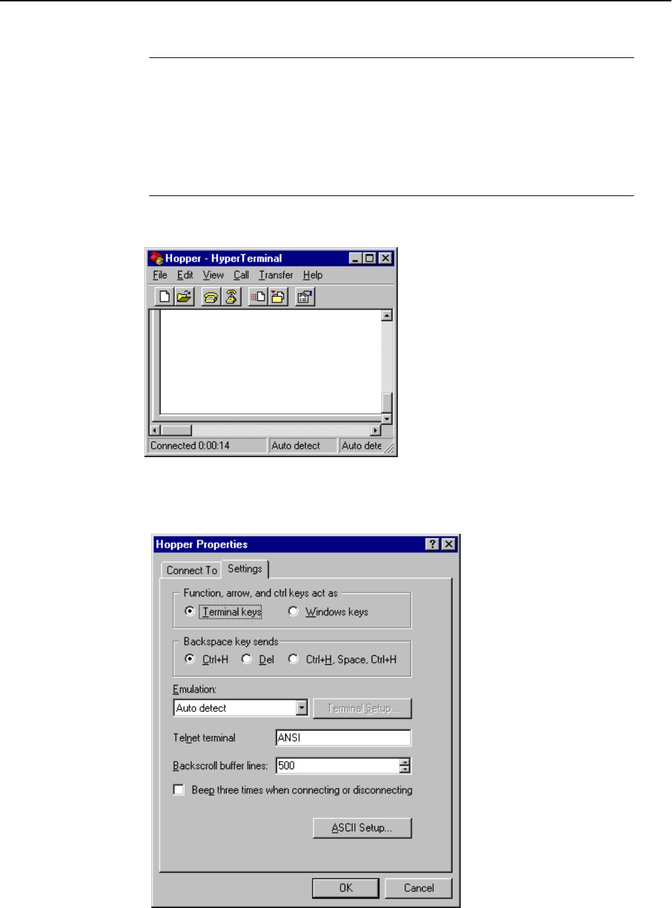
Starting HyperTerminal
Version 1.0 Rev B - 08/00 89
6. Enter the following settings:
7. Click OK. The Hopper - HyperTerminal window is displayed:
8. From the File menu, select Properties. The Hopper Properties window is displayed:
Bits per second 9600
Data bits 8
Parity None
Stop bits 1
Flow control None
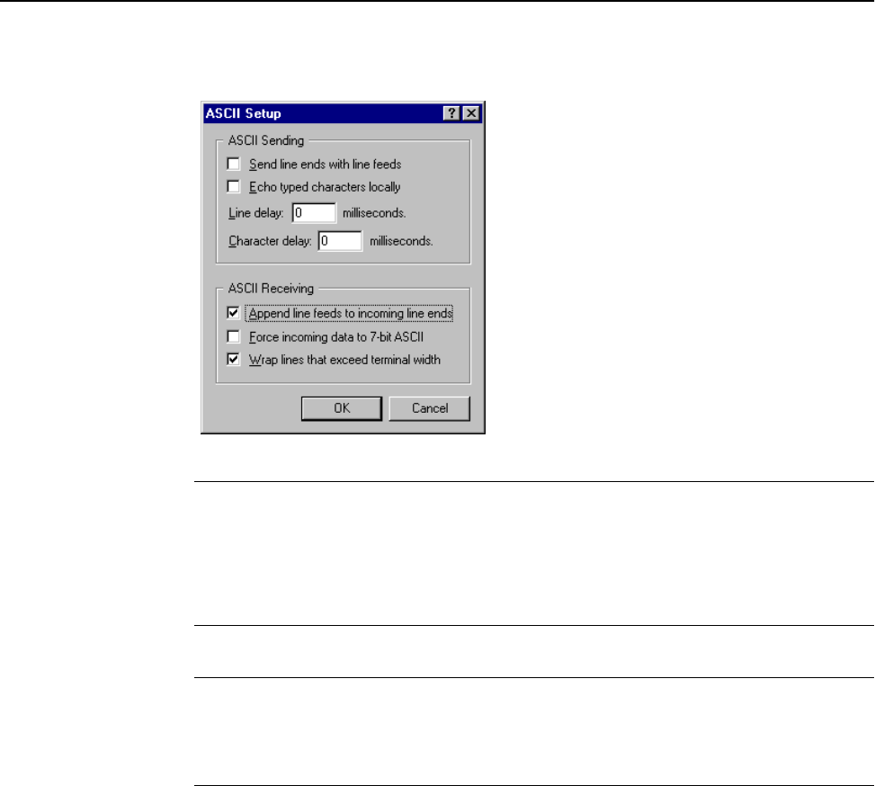
Appendix B: Using HyperTerminal
90 Version 1.0 Rev B - 08/00
9. Click the Settings tab and then click ASCII Setup. The ASCII Setup window is
displayed:
10. In the ASCII Sending area, choose the following settings:
11. In the ASCII Receiving area, do the following:
12. Click OK. The ASCII Setup window closes.
13. Click OK. The Hopper Properties window closes.
14. Use a cross-connect RS-232 serial cable to connect the communications port of the PC
to the DB9 connector on the Hopper Plus 120-24.
15. Power up the Hopper Plus 120-24 unit.
16. Press Enter. The Hopper Plus 120-24 Configuration menu is displayed in the
HyperTerminal window.
Send line ends with line feeds Clear the checkbox.
Echo typed characters locally Clear the checkbox.
Line delay Type 0.
Character delay Type 0.
Append line feeds to incoming line ends Click to select the checkbox.
Force incoming data to 7-bit ASCII Clear the checkbox.
Wrap lines that exceed terminal width Click to select the checkbox.
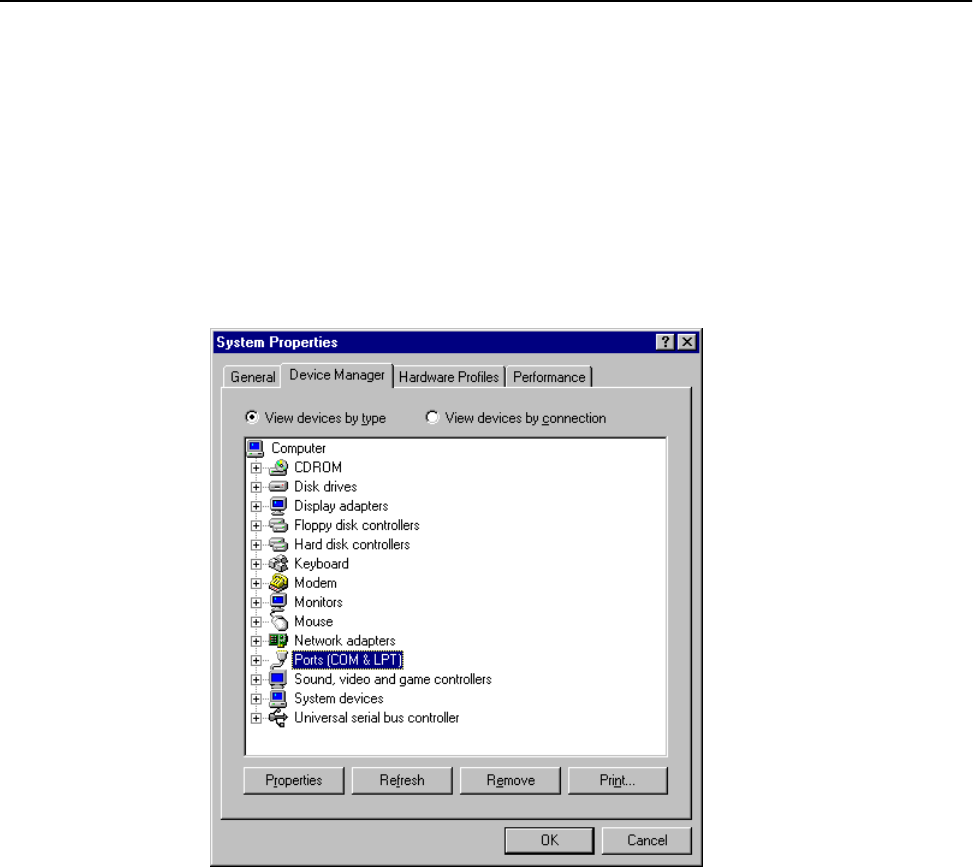
Determining the Communications Port
Version 1.0 Rev B - 08/00 91
Determining the Communications Port
To set the communications port in the HyperTerminal session, you need to know which
communications port you are using on your computer. Most laptops are connected through
COM 1, but PCs can use COM 1 through 3.
To determine the communications port
1. Right-click the My Computer icon on your desktop and from the shortcut menu,
select Properties. The System Properties window is displayed:
2. Click the Device Manager tab and click Ports (COM & LPT). A list of the
available communications ports appears.
3. Select the appropriate port for your HyperTerminal session.
Note: A connection to the Hopper Plus 120-24 Configuration menus will not be
established if the wrong port is selected. If this occurs, reconfigure the HyperTerminal to
connect using another available communications port.

Appendix B: Using HyperTerminal
92 Version 1.0 Rev B - 08/00
Version 1.0 Rev B - 08/00 93
Appendix C: Configuring a Simple Data Network
A simple peer-to-peer network can be configured to perform file transfers between two
computers. This section describes the following:
¥ Checking the Network Adaptor Installation
¥ Configuring the Network
¥ Enabling the Sharing Feature on the Hard Disk Drive
Checking the Network Adaptor Installation
To check the network adaptor installation
1. From the Start menu, select Settings, Control Panel. The Control Panel window
appears.
2. Double-click the System icon. The System Properties window appears.
3. Click the Device Manager tab.
4. Double-click Network Adapters. A list of installed devices appears.
5. Check for trouble indicators with the previously installed network adaptor(s).
6. Click OK. The Control Panel window appears.
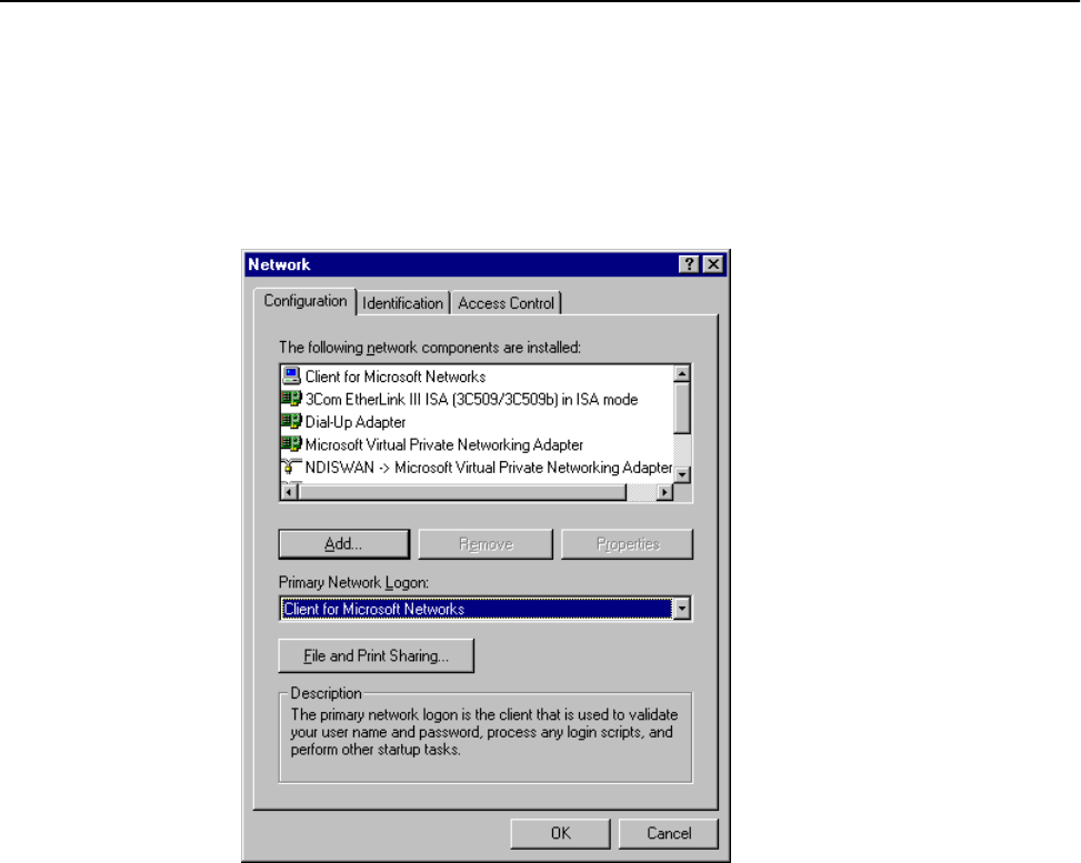
Appendix C: Configuring a Simple Data Network
94 Version 1.0 Rev B - 08/00
Configuring the Network
To configure the network
1. In the Control Panel window, double-click the Network icon. The Network window
is displayed:
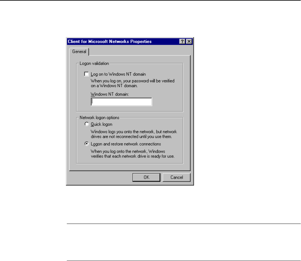
Configuring the Network
Version 1.0 Rev B - 08/00 95
2. In the list of network components area, double-click Client for Microsoft
Networks. The Client for Microsoft Networks Properties window is displayed:
Note: If Client for Microsoft Networks is not listed, click Add and select
Client, Add, Microsoft, Client for Microsoft Networks, and then click OK.
3. In the Client for Microsoft Networks Properties window, do the following:
4. Click OK. The Client for Microsoft Networks Properties window closes.
Log on to Windows NT domain Clear the checkbox.
Windows NT domain Clear the field.
Logon and restore network connections. Click the button.
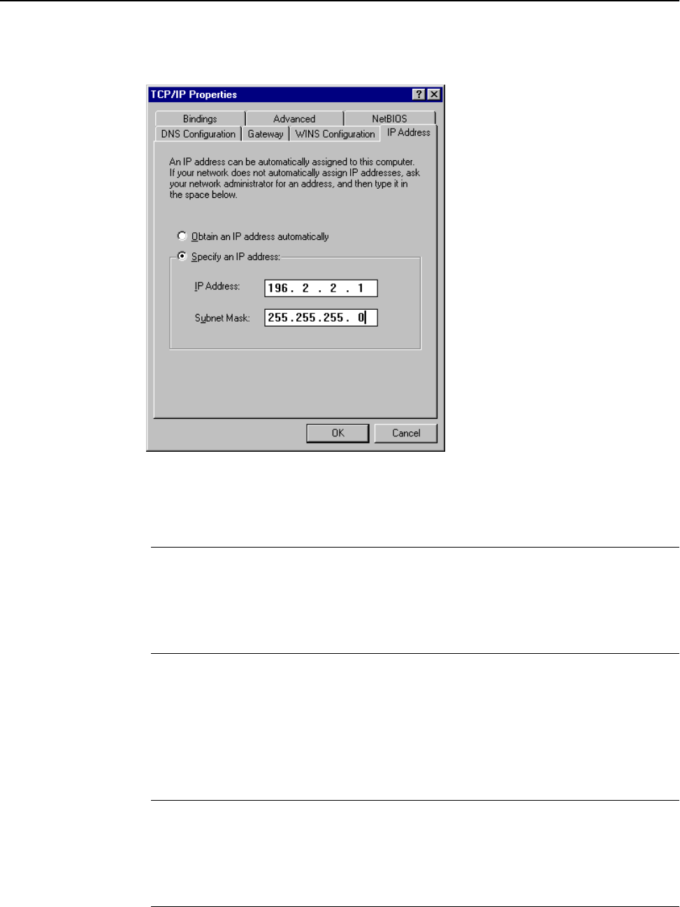
Appendix C: Configuring a Simple Data Network
96 Version 1.0 Rev B - 08/00
5. In the Network window, double-click TCP/IP. The TCP/IP Properties window is
displayed:
Note: If TCP/IP is not listed in the Network window, click Add and select
Protocol, Add, Microsoft, TCP/IP, and then click OK.
6. Click the IP Address tab.
7. Click Specify an IP Address, and type the following:
8. Click OK.
9. Click File and Print Sharing. The File and Print Sharing window appears.
10. Click to select the I want to be able to give others access to my files
checkbox.
11. Click OK.
12. In the Network window, click the Identification tab and type the following:
IP Address 196.2.2.1
Note: Increment the last digit by 1 (i.e. type 196.2.2.2)
when configuring the second computer.
Subnet Mask 255.255.255.0
Note: This number is the same for both computers.
Computer Name A unique name for each computer. For example,
computer 1 and computer 2.
Workgroup A workgroup name. For example, Test.
Note: All computers in the network must have the
same workgroup name.
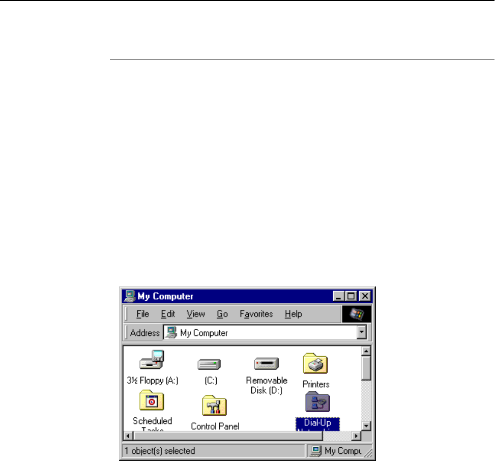
Enabling the Sharing Feature on the Hard Disk Drive
Version 1.0 Rev B - 08/00 97
13. In the Network window, click the Access Control tab.
14. Click Share Level Access Control.
15. Click OK.
16. You are prompted to restart your computer.
17. Click Yes.
Wait for your computer to restart, then proceed with Enabling the Sharing Feature on
the Hard Disk Drive.
Enabling the Sharing Feature on the Hard Disk Drive
To enable the sharing feature on the hard disk drive
1. On the desktop, double-click My Computer. The My Computer window is
displayed:
Computer Description A description of the type of computer used. For
example, laptop or desktop.
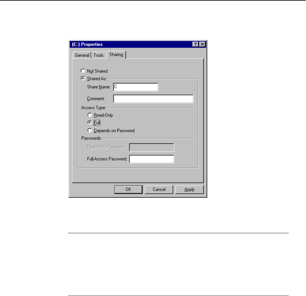
Appendix C: Configuring a Simple Data Network
98 Version 1.0 Rev B - 08/00
2. Right-click the hard disk drive icon (typically drive C:), and select Open. The
Properties window is displayed:
3. Click the Sharing tab, and choose the following:
4. Click OK.
5. Repeat this procedure for all PCs in the network.
Once all PCs in the network have been shared, you can view the network by double
clicking the Network Neighborhood icon that appears on each PC desktop.
Shared As Click the radio button.
Share Name Type C.
Comment Leave this field blank.
Access Type Click to select Full.
Passwords Leave these fields blank.

Version 1.0 Rev B - 08/00 99
Appendix D: SNMP MIB
About SNMP MIB
Simple Network Management Protocol (SNMP) Management Information Block (MIB)
software is included with each Hopper Plus unit. It enables you to configure, monitor, and
control units via the Ethernet or air. (SNMP-compatible network management software is
available commercially and as shareware.)
Units in remote and hard-to-reach locations can be easily configured, and network
managers can avoid or reduce downtime by monitoring network throughput, packet
collision rates, and interference.
SNMP is a protocol used to remotely manage network elements by polling, setting
terminal values, and monitoring network statistics and events. It provides a mechanism for
the exchange of management information in a TCP/IP-based Internet environment.
Community names are used by the SNMP manager to determine access privileges (see
Setting Community Names on page 58).
SNMP consists of three elements.
SNMP Element Description
Manager Is installed on the network’s host computer
and is controlled by the network
administrator. From the host, the Manager
configures Agents, or polls Agents for
information.
Agent Runs on each unit. An Agent accepts
configuration commands from the Manager
and collects network and terminal
information specified in the MIB.
Management Information Block (MIB) Is a database that is accessed by a specific
set of commands that you execute using the
SNMP manager. There is a standard MIB
and a Wi-LAN customized MIB that stores
information relevant to the operation of a
wireless network.

Appendix D: SNMP MIB
100 Version 1.0 Rev B - 08/00
Wi-LAN Object Identifier Nodes
The Hopper Plus 120-24 uses SNMP version 1, which is MIB 2 compliant. All OID
(Object Identifier) nodes in the 120-24 private Wi-LAN MIB are numbered
1.3.6.1.4.1.2686.2.n where n is a private Wi-LAN MIB node number or branch of nodes.
All nodes containing statistical information are cleared on power up and reset.
Values in all writeable nodes are stored in FLASH and are retained until overwritten by
the administrator, even following power down or reset.
From To Classification
1.3.6.1.4.1.2686.2.1.1 1.3.6.1.4.1.2686.2.1.104 Configuration
1.3.6.1.4.1.2686.2.1.100.1 1.3.6.1.4.1.2686.2.1.100.7 Configuration:
System Image List
1.3.6.1.4.1.2686.2.2.1 1.3.6.1.4.1.2686.2.2.7 System Status
1.3.6.1.4.1.2686.2.3.1 1.3.6.1.4.1.2686.2.3.32 Statistics
1.3.6.1.4.1.2686.2.4.1 1.3.6.1.4.1.2686.2.4.7 System Commands

Using Object Identifier Nodes
Version 1.0 Rev B - 08/00 101
Using Object Identifier Nodes
Following are descriptions of the nodes in the Hopper Plus 120-24 MIB:
Group Node Label Address/Node Syntax Access Description
Configuration serialNumber 1.3.6.1.4.1.2686.2.1.1 DisplayString
(0..15)
Read Only The Hopper Plus 120-24 unit Serial Number.
Configuration productionDate 1.3.6.1.4.1.2686.2.1.2 DisplayString
(0..15)
Read Only The Hopper Plus 120-24 unit Date of
Manufacture.
Configuration macAddress 1.3.6.1.4.1.2686.2.1.3 PhysAddress Read Only Ethernet MAC Address.
Configuration systemName 1.3.6.1.4.1.2686.2.1.4 DisplayString
(0..31)
Read/Write The Hopper Plus 120-24 unit System Name.
Configuration unitLocation 1.3.6.1.4.1.2686.2.1.5 DisplayString
(0..31)
Read/Write User configurable Unit Location.
Configuration contactName 1.3.6.1.4.1.2686.2.1.6 DisplayString
(0..31)
Read/Write User configurable Contact Name.
Configuration config7 1.3.6.1.4.1.2686.2.1.7 INTEGER Spare.
Configuration config8 1.3.6.1.4.1.2686.2.1.8 INTEGER Spare.
Configuration config9 1.3.6.1.4.1.2686.2.1.9 INTEGER Spare.
Configuration ipAddress 1.3.6.1.4.1.2686.2.1.10 IpAddress Read Only Internet IP Address: default = 192.168.1.100.
Configuration ipNewAddress 1.3.6.1.4.1.2686.2.1.11 IpAddress Read/Write New Internet IP Address.
Configuration ipSubnetMask 1.3.6.1.4.1.2686.2.1.12 IpAddress Read/Write IP Subnet Mask: default = 255.255.255.0.
Configuration ipGatewayAddr 1.3.6.1.4.1.2686.2.1.13 IpAddress Read/Write IP default gateway address (currently not
used).
Configuration ipNetmanAddr 1.3.6.1.4.1.2686.2.1.14 IpAddress Read/Write SNMP network management station IP
address.
Configuration ipPacketFiltering 1.3.6.1.4.1.2686.2.1.15 INTEGER Read/Write IP packet filtering: 0 = disabled, 1 = enabled.
Configuration ipAddressFiltering 1.3.6.1.4.1.2686.2.1.16 INTEGER Read/Write IP address filtering: 0 = disabled, 1 = enabled.

Appendix D: SNMP MIB
102 Version 1.0 Rev B - 08/00
Configuration ipFilter1Range 1.3.6.1.4.1.2686.2.1.17 INTEGER Read/Write IP address filter 1 range: (0-255).
Configuration ipFilter1Base 1.3.6.1.4.1.2686.2.1.18 IpAddress Read/Write IP filter 1 base address.
Configuration ipFilter2Range 1.3.6.1.4.1.2686.2.1.19 INTEGER Read/Write IP address filter 2 range: (0-255).
Configuration ipFilter2Base 1.3.6.1.4.1.2686.2.1.20 IpAddress Read/Write IP filter 2 base address.
Configuration ipFilter3Range 1.3.6.1.4.1.2686.2.1.21 INTEGER Read/Write IP address filter 3 range: (0-255).
Configuration ipFilter3Base 1.3.6.1.4.1.2686.2.1.22 IpAddress Read/Write IP filter 3 base address.
Configuration ipFilter4Range 1.3.6.1.4.1.2686.2.1.23 INTEGER Read/Write IP address filter 4 range: (0-255).
Configuration ipFilter4Base 1.3.6.1.4.1.2686.2.1.24 IpAddress Read/Write IP filter 4 base address.
Configuration ipFilter5Range 1.3.6.1.4.1.2686.2.1.25 INTEGER Read/Write IP address filter 5 range: (0-255).
Configuration ipFilter5Base 1.3.6.1.4.1.2686.2.1.26 IpAddress Read/Write IP filter 5 base address.
Configuration config27 1.3.6.1.4.1.2686.2.1.27 INTEGER Spare.
Configuration config28 1.3.6.1.4.1.2686.2.1.28 INTEGER Spare.
Configuration config29 1.3.6.1.4.1.2686.2.1.29 INTEGER Spare.
Configuration stationType 1.3.6.1.4.1.2686.2.1.30 INTEGER Read Only Current station type: 0 = remote, 1 = base.
Configuration stationRank 1.3.6.1.4.1.2686.2.1.31 INTEGER Read Only Current station RF rank: 1 to 1000.
Configuration centerFreq 1.3.6.1.4.1.2686.2.1.32 INTEGER Read Only Current RF center frequency (GHz)
Configuration securityWord1 1.3.6.1.4.1.2686.2.1.33 INTEGER Read Only Current RF security password 1.
Group Node Label Address/Node Syntax Access Description
Channel Frequency Channel Frequency
1 2.4258 5 2.4455
2 2.4302 6 2.4498
3 2.4345 7 2.4542
4 2.4400

Using Object Identifier Nodes
Version 1.0 Rev B - 08/00 103
Configuration securityWord2 1.3.6.1.4.1.2686.2.1.34 INTEGER Read Only Current RF security password 2.
Configuration securityWord3 1.3.6.1.4.1.2686.2.1.35 INTEGER Read Only Current RF security password 3.
Configuration securityWord4 1.3.6.1.4.1.2686.2.1.36 INTEGER Read Only Current RF security password 4.
Configuration securityWord5 1.3.6.1.4.1.2686.2.1.37 INTEGER Read Only Current RF security password 5.
Configuration scramblingCode 1.3.6.1.4.1.2686.2.1.38 INTEGER Read Only Current RF scrambling code word.
Configuration acquisitionCode 1.3.6.1.4.1.2686.2.1.39 INTEGER Read Only Current RF acquisition code (0-15).
Configuration configMinutes 1.3.6.1.4.1.2686.2.1.40 INTEGER Read Only Current RF configuration test minutes (1-
120).
Configuration repeaterMode 1.3.6.1.4.1.2686.2.1.41 INTEGER Read Only Current base station repeater mode: 0 =
disabled, 1 = enabled.
Configuration systemType 1.3.6.1.4.1.2686.2.1.42 INTEGER Read Only Current base station symmetry: 0 =
asymmetric, 1 = symmetric.
Configuration remoteGroup 1.3.6.1.4.1.2686.2.1.43 INTEGER Read Only Current RF group identifier: 0 = closed, 1 - 63
= special group.
Configuration config44 1.3.6.1.4.1.2686.2.1.44 INTEGER Spare.
Configuration config45 1.3.6.1.4.1.2686.2.1.45 INTEGER Spare.
Configuration defStationType 1.3.6.1.4.1.2686.2.1.46 INTEGER Read Only Default Station type: 0 = remote, 1 = base.
Configuration defStationRank 1.3.6.1.4.1.2686.2.1.47 INTEGER Read Only Default Station RF Rank.
Group Node Label Address/Node Syntax Access Description

Appendix D: SNMP MIB
104 Version 1.0 Rev B - 08/00
Configuration defCenterFreq 1.3.6.1.4.1.2686.2.1.48 INTEGER Read Only FLASH RF center frequency (GHz)
Configuration defSecurityWord1 1.3.6.1.4.1.2686.2.1.49 INTEGER Read Only Default RF security password 1.
Configuration defSecurityWord2 1.3.6.1.4.1.2686.2.1.50 INTEGER Read Only Default RF security password 2.
Configuration defSecurityWord3 1.3.6.1.4.1.2686.2.1.51 INTEGER Read Only Default RF security password 3.
Configuration defSecurityWord4 1.3.6.1.4.1.2686.2.1.52 INTEGER Read Only Default RF security password 4.
Configuration defSecurityWord5 1.3.6.1.4.1.2686.2.1.53 INTEGER Read Only Default RF security password 5.
Configuration defScramblingCode 1.3.6.1.4.1.2686.2.1.54 INTEGER Read Only Default RF scrambling code word.
Configuration defAcquisitionCode 1.3.6.1.4.1.2686.2.1.55 INTEGER Read Only Default RF acquisition code (0-15).
Configuration defConfigMinutes 1.3.6.1.4.1.2686.2.1.56 INTEGER Read Only Default RF configuration test minutes (1-120).
Configuration deRepeaterMode 1.3.6.1.4.1.2686.2.1.57 INTEGER Read Only Default base station repeater mode: 0 =
disabled, 1 = enabled.
Configuration defSystemType 1.3.6.1.4.1.2686.2.1.58 INTEGER Read Only Default base station symmetry type: 0 =
asymmetric, 1 = symmetric.
Configuration defRemoteGroup 1.3.6.1.4.1.2686.2.1.59 INTEGER Read Only Default RF group identifier: 0 = closed, 1 - 63
= special group.
Configuration config60 1.3.6.1.4.1.2686.2.1.60 INTEGER Spare.
Configuration config61 1.3.6.1.4.1.2686.2.1.61 INTEGER Spare.
Configuration newStationType 1.3.6.1.4.1.2686.2.1.62 INTEGER Read/Write New station type: 0 = remote, 1 = base.
Group Node Label Address/Node Syntax Access Description
Channel Frequency Channel Frequency
1 2.4258 5 2.4455
2 2.4302 6 2.4498
3 2.4345 7 2.4542
4 2.4400

Using Object Identifier Nodes
Version 1.0 Rev B - 08/00 105
Configuration newStationRank 1.3.6.1.4.1.2686.2.1.63 INTEGER Read/Write New station RF rank (1-1000).
Configuration newCenterFreq 1.3.6.1.4.1.2686.2.1.64 INTEGER Read/Write New RF center frequency (GHz)
Configuration newSecurityWord1 1.3.6.1.4.1.2686.2.1.65 INTEGER Read/Write New RF security password 1.
Configuration newSecurityWord2 1.3.6.1.4.1.2686.2.1.66 INTEGER Read/Write New RF security password 2.
Configuration newSecurityWord3 1.3.6.1.4.1.2686.2.1.67 INTEGER Read/Write New RF security password 3.
Configuration newSecurityWord4 1.3.6.1.4.1.2686.2.1.68 INTEGER Read/Write New RF security password 4.
Configuration newSecurityWord5 1.3.6.1.4.1.2686.2.1.69 INTEGER Read/Write New RF security password 5.
Configuration newScramblingCode 1.3.6.1.4.1.2686.2.1.70 INTEGER Read/Write New RF scrambling code word.
Configuration newAcquisitionCode 1.3.6.1.4.1.2686.2.1.71 INTEGER Read/Write New RF acquisition code (0-15).
Configuration newConfigMinutes 1.3.6.1.4.1.2686.2.1.72 INTEGER Read/Write New RF configuration test minutes (1-120).
Configuration newRepeaterMode 1.3.6.1.4.1.2686.2.1.73 INTEGER Read/Write New base station repeater mode: 0 =
disabled, 1 = enabled.
Configuration newSystemType 1.3.6.1.4.1.2686.2.1.74 INTEGER Read/Write New base station symmetry type: 0 =
asymmetric, 1 = symmetric.
Configuration newRemoteGroup 1.3.6.1.4.1.2686.2.1.75 INTEGER Read/Write New RF group identifier: 0 = closed, 1 - 63 =
special group.
Configuration config76 1.3.6.1.4.1.2686.2.1.76 INTEGER Spare.
Configuration config77 1.3.6.1.4.1.2686.2.1.77 INTEGER Spare.
Group Node Label Address/Node Syntax Access Description
Channel Frequency Channel Frequency
1 2.4258 5 2.4455
2 2.4302 6 2.4498
3 2.4345 7 2.4542
4 2.4400

Appendix D: SNMP MIB
106 Version 1.0 Rev B - 08/00
Configuration stationMode 1.3.6.1.4.1.2686.2.1.78 INTEGER Read/Write Operating mode: 0 = normal, 1 = Rx Test, 2 =
Tx Test, 3 = RSSI Test.
Configuration rfTransmitStatus 1.3.6.1.4.1.2686.2.1.79 INTEGER Read/Write RF transmit status: 0 = blocked, 1 =
unblocked.
Configuration linkMonitorPeriod 1.3.6.1.4.1.2686.2.1.80 INTEGER Read/Write Link monitor period (0-10000): 0 = disabled, 1
- 10,000 = number of data superframes per
single test superframe.
Configuration testModeTimer 1.3.6.1.4.1.2686.2.1.81 INTEGER Read/Write Test mode timer minutes (1-1000).
Configuration dynamicPolling 1.3.6.1.4.1.2686.2.1.82 INTEGER Read/Write Dynamic polling level (1-60).
Configuration remoteDistance 1.3.6.1.4.1.2686.2.1.83 INTEGER Read/Write Maximum remote unit distance (km)
Configuration linkMonitorRank 1.3.6.1.4.1.2686.2.1.84 INTEGER Read/Write Link monitor remote station rank (1-1000).
Configuration throttleEnable 1.3.6.1.4.1.2686.2.1.85 INTEGER Read/Write Throttling enable: 0 = disabled, 1 = enabled.
Configuration throttleLevel 1.3.6.1.4.1.2686.2.1.86 INTEGER Read/Write RF throttle level (1-50).
Configuration config87 1.3.6.1.4.1.2686.2.1.87 INTEGER Spare.
Configuration config88 1.3.6.1.4.1.2686.2.1.88 INTEGER Spare.
Configuration config89 1.3.6.1.4.1.2686.2.1.89 INTEGER Spare.
Configuration communityName1 1.3.6.1.4.1.2686.2.1.90 DisplayString
(0..15)
Read/Write Read-only access community name.
Group Node Label Address/Node Syntax Access Description
Channel Frequency Channel Frequency
1 2.4258 5 2.4455
2 2.4302 6 2.4498
3 2.4345 7 2.4542
4 2.4400

Using Object Identifier Nodes
Version 1.0 Rev B - 08/00 107
Configuration communityName2 1.3.6.1.4.1.2686.2.1.91 DisplayString
(0..15)
Read/Write Read-Write access community name.
Configuration ethernetAccess 1.3.6.1.4.1.2686.2.1.92 INTEGER Read Only Ethernet access to local host: 0 = disabled, 1
= enabled.
Configuration wirelessAccess 1.3.6.1.4.1.2686.2.1.93 INTEGER Read Only Wireless access to local host: 0 = disabled, 1
= enabled.
Configuration config94 1.3.6.1.4.1.2686.2.1.94 INTEGER Spare.
Configuration currentImage 1.3.6.1.4.1.2686.2.1.95 DisplayString
(0..15)
Read Only Current system image file name.
Configuration defaultImage 1.3.6.1.4.1.2686.2.1.96 DisplayString
(0..15)
Read/Write Selects specified system image file as
default.
Configuration prevDefaultImage 1.3.6.1.4.1.2686.2.1.97 DisplayString
(0..15)
Read Only Previous default system image file name.
Configuration config98 1.3.6.1.4.1.2686.2.1.98 INTEGER Spare.
Configuration config99 1.3.6.1.4.1.2686.2.1.99 INTEGER Spare.
Configuration systemImageList 1.3.6.1.4.1.2686.2.1.100 SEQUENCE
OF
SystemImage
Entry
N/A System Image List Branch.
Configuration:
System Image
List
systemImageNumber 1.3.6.1.4.1.2686.2.1.100.1 INTEGER Read Only System image number.
Configuration:
System Image
List
systemImageName 1.3.6.1.4.1.2686.2.1.100.2 DisplayString
(0..15)
Read Only System image file name.
Configuration:
System Image
List
systemImageRevn 1.3.6.1.4.1.2686.2.1.100.3 DisplayString
(0..15)
Read Only System image revision identifier.
Group Node Label Address/Node Syntax Access Description

Appendix D: SNMP MIB
108 Version 1.0 Rev B - 08/00
Configuration:
System Image
List
systemImageDate 1.3.6.1.4.1.2686.2.1.100.4 DisplayString
(0..15)
Read Only System image file date.
Configuration:
System Image
List
systemImageTime 1.3.6.1.4.1.2686.2.1.100.5 DisplayString
(0..15)
Read Only Time system image file was last changed.
Configuration:
System Image
List
systemImageSize 1.3.6.1.4.1.2686.2.1.100.6 INTEGER Read Only System image file size.
Configuration:
System Image
List
systemImageText 1.3.6.1.4.1.2686.2.1.100.7 DisplayString
(0..15)
Read Only System image descriptive text.
Configuration config101 1.3.6.1.4.1.2686.2.1.101 INTEGER Spare.
Configuration config102 1.3.6.1.4.1.2686.2.1.102 INTEGER Spare.
Configuration config103 1.3.6.1.4.1.2686.2.1.103 INTEGER Spare.
Configuration config104 1.3.6.1.4.1.2686.2.1.104 INTEGER Spare.
System Status totalHours 1.3.6.1.4.1.2686.2.2.1 Counter Read Only Cumulative run-time hours.
System Status systemHours 1.3.6.1.4.1.2686.2.2.2 Counter Read Only Current run-time hours since powerup.
System Status loginOkays 1.3.6.1.4.1.2686.2.2.3 Counter Read Only Number of successful logins.
System Status loginFails 1.3.6.1.4.1.2686.2.2.4 Counter Read Only Number of unsuccessful login attempts.
System Status localUser 1.3.6.1.4.1.2686.2.2.5 INTEGER Read Only Local user login status: 0 = none, 1 = user, 2
= supervisor.
System Status telnetUser 1.3.6.1.4.1.2686.2.2.6 INTEGER Read Only Telnet user login status: 0 = none, 1 = user, 2
= supervisor.
System Status ftpUser 1.3.6.1.4.1.2686.2.2.7 INTEGER Read Only FTP user login status: 0 = none, 1 = user, 2 =
supervisor.
Statistics etherRxTotalPkts 1.3.6.1.4.1.2686.2.3.1 Counter Read Only Total Ethernet packets received.
Statistics etherRxLocalPkts 1.3.6.1.4.1.2686.2.3.2 Counter Read Only Ethernet packets received for local host.
Group Node Label Address/Node Syntax Access Description

Using Object Identifier Nodes
Version 1.0 Rev B - 08/00 109
Statistics etherRxErrorPkts 1.3.6.1.4.1.2686.2.3.3 Counter Read Only Ethernet packets received in error.
Statistics etherRxDroppedPkts 1.3.6.1.4.1.2686.2.3.4 Counter Read Only Number of received Ethernet packets
dropped.
Statistics etherRxDiscardPkts 1.3.6.1.4.1.2686.2.3.5 Counter Read Only Number of received Ethernet packets
discarded.
Statistics etherTxTotalPkts 1.3.6.1.4.1.2686.2.3.6 Counter Read Only Total Ethernet packets transmitted.
Statistics etherTxDroppedPkts 1.3.6.1.4.1.2686.2.3.7 Counter Read Only Number of transmitted Ethernet packets
dropped.
Statistics rfRxTotalPkts 1.3.6.1.4.1.2686.2.3.8 Counter Read Only Total received RF packets.
Statistics rfRxLocalPkts 1.3.6.1.4.1.2686.2.3.9 Counter Read Only Total received RF packets for local host.
Statistics rfRxDroppedPkts 1.3.6.1.4.1.2686.2.3.10 Counter Read Only Number of received RF packets dropped.
Statistics rfRxDiscardedPkts 1.3.6.1.4.1.2686.2.3.11 Counter Read Only Number of received RF packets discarded.
Statistics rfTxTotalPkts 1.3.6.1.4.1.2686.2.3.12 Counter Read Only Total transmitted RF packets.
Statistics rfTxLocalPkts 1.3.6.1.4.1.2686.2.3.13 Counter Read Only Number of transmitted local RF packets.
Statistics rfTxDroppedPkts 1.3.6.1.4.1.2686.2.3.14 Counter Read Only Number of transmitted RF packets dropped.
Statistics rfRxSframeCount 1.3.6.1.4.1.2686.2.3.15 Counter Read Only Total RF super frames received.
Statistics rfRxOverrunErrors 1.3.6.1.4.1.2686.2.3.16 Counter Read Only Number of RF overrun errors.
Statistics rfRxSFrameErrors 1.3.6.1.4.1.2686.2.3.17 Counter Read Only Number of RF super frame control word
errors.
Statistics rfRxChecksumErrors 1.3.6.1.4.1.2686.2.3.18 Counter Read Only Number of RF super frame header checksum
errors.
Statistics rfRxPacketErrors 1.3.6.1.4.1.2686.2.3.19 Counter Read Only Number of RF packet control work errors.
Statistics rfRxLengthErrors 1.3.6.1.4.1.2686.2.3.20 Counter Read Only Number of RF super frame length errors.
Statistics rfTxSuperFrameCnt 1.3.6.1.4.1.2686.2.3.21 Counter Read Only Number of RF super frames transmitted.
Statistics rfEtoIThroughput 1.3.6.1.4.1.2686.2.3.22 Counter Read Only Ethernet to RF throughput.
Group Node Label Address/Node Syntax Access Description

Appendix D: SNMP MIB
110 Version 1.0 Rev B - 08/00
Statistics rfItoEThroughput 1.3.6.1.4.1.2686.2.3.23 Counter Read Only RF to Ethernet throughput.
Statistics statistics24 1.3.6.1.4.1.2686.2.3.24 Counter Spare.
Statistics linkMonitorRank1 1.3.6.1.4.1.2686.2.3.25 INTEGER Read Only Link monitor remote station rank.
Statistics linkMonRtoBber 1.3.6.1.4.1.2686.2.3.26 DisplayString
(0..8)
Read Only Link monitor remote to base bit error rate.
Statistics linkMonBtoRber 1.3.6.1.4.1.2686.2.3.27 DisplayString
(0..8)
Read Only Link monitor base to remote bit error rate.
Statistics linkMonMissPktCnt 1.3.6.1.4.1.2686.2.3.28 Counter Read Only Link monitor missed packet count.
Statistics linMonEnvPBtoR 1.3.6.1.4.1.2686.2.3.29 INTEGER Read Only Link monitor base to remote envelope power.
Statistics linkMonEnvPRtoB 1.3.6.1.4.1.2686.2.3.30 INTEGER Read Only Link monitor remote to base envelope power.
Statistics linkMonCorrPBtoR 1.3.6.1.4.1.2686.2.3.31 INTEGER Read Only Link monitor base to remote correlation
power.
Statistics linkMonCorrPRtoB 1.3.6.1.4.1.2686.2.3.32 INTEGER Read Only Link monitor remote to base correlation
power.
System
Commands
rebootCurrent 1.3.6.1.4.1.2686.2.4.1 INTEGER Read/Write Reboot current system image: 1 = reboot.
System
Commands
rebootImage 1.3.6.1.4.1.2686.2.4.2 DisplayString
(0..15)
Read/Write Reboot specified system image: system
image file name.
System
Commands
rebootnewRFConfig 1.3.6.1.4.1.2686.2.4.3 INTEGER Read/Write Reboot new RF configuration: 1 = reboot.
System
Commands
restFactConfReboot 1.3.6.1.4.1.2686.2.4.4 INTEGER Read/Write Restore factory configuration and reboot: 1 =
restore.
System
Commands
saveConfToFlash 1.3.6.1.4.1.2686.2.4.5 INTEGER Read/Write Save current configuration to flash: 1 = save.
System
Commands
resetRadioStats 1.3.6.1.4.1.2686.2.4.6 INTEGER Read/Write Reset radio statistics: 1 = reset.
System
Commands
resetEthernetStats 1.3.6.1.4.1.2686.2.4.7 INTEGER Read/Write Reset Ethernet statistics: 1 = reset.
Group Node Label Address/Node Syntax Access Description

Version 1.0 Rev B - 08/00 111
Appendix E: Technical Reference Information
Front Panel LEDs
.
LED Type Color Status
AIR Orange
(both units)
The units are configured correctly: the base and
remote units are transmitting and receiving data.
Green
(remote)
The units are configured incorrectly: the remote
unit is receiving data from the air but can not
respond.
Red
(base)
The units are configured incorrectly: the base
unit is transmitting without receiving
acknowledgment.
Off Listening to the air
MODE Green Receive test mode - RS-232 displays statistics
Red Continuous Transmit test mode
Orange RSSI test mode - measures fade margin
Off Normal transceiver mode
WIRE Green Receiving data from the wire
Red Transmitting data to the wire
Orange Transmitting and receiving data on the wire
Off Listening to the wire
POWER Green Power is connected to the transceiver
Off No power is connected to the transceiver
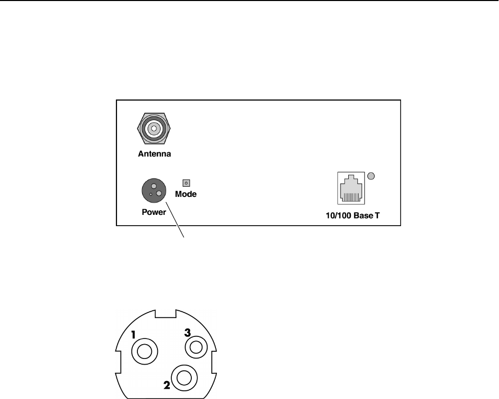
Appendix E: Technical Reference Information
112 Version 1.0 Rev B - 08/00
Power Connector Pinout
Power Connector
Hopper PLUS 120-24, Rear View
Pin 1 +12 VDC
Pin 2 GND
Pin 3 N/C
Power Connector Pinout
Version 1.0 Rev B - 08/00 113
Glossary
A
absorption
Antennas mounted too close to soft objects, such as trees, may experience a reduction in
signal strength due to absorption. Absorption is most often encountered in applications
installed during the fall or winter months. The problem does not become evident until the
spring.
acquisition code
To minimize the effects of interference, all units in a system use the same acquisition code
so the receivers can distinguish the desired signal from interfering signals.
agent
In an SNMP context, the agent runs on each unit. An agent accepts configuration
commands from the manager and collects network and terminal information specified in
the MIB.
antenna
A device which accepts electromagnetic energy from a circuit or wire and radiates it into
space rather than confining it.
antenna gain
Gain of the antenna over a dipole (dBd) or isotropic (dBi).
¥ Antennas have a gain associated with them, which is a measure of their ability to
amplify signals in their tuned band.
¥ Antenna gain is achieved by focusing the signal. A higher gain antenna has more
compressed signal.
attenuation
Any loss in signal strength, due to resistance, absorption, capacitance, or any
characteristic of the medium or design of the system.
B
beamwidth
The beamwidth of an antenna describes how a signal spreads out from the antenna as well
as the range of the reception area. Beamwidth is measured between the points on the beam
pattern at which the power density is half of the maximum power. This is often referred to

Glossary
114 Version 1.0 Rev B - 08/00
as the -3 dB points. A high gain antenna has a very narrow beamwidth and may be more
difficult to align.
BER
Bit Error Rate. A percentage of bits per million, showing the number of bits in error
compared to the data bits actually sent.
blocking
Blocking is an operating mode where the radio receives only. Unblocked is the normal
operating mode.
C
cable loss
The signal loss experienced as it passes through the coax cable. Expressed in dB.
channel
The width of the spectrum band taken by a radio signal, usually measured in
kilohertz (kHz).
coaxial cable
A type of wire where the inner conductor is surrounded by an outer conductor. The outer
conductor serves as an electrical shield.
collision
The situation that exists when two users try to send a signal over the same medium at the
same time, and the signal uses the same frequencies.
configuration menus
The menu based user interface on the Hopper Plus 120-24 that allows the viewing and
configuration of Hopper Plus 120-24 parameters.
contentionless polling
The Hopper Plus 120-24 uses a form of dynamic polling that ignores idle remote stations.
The number of polls that an idle remote is ignored can be set to maximize polling to active
stations.
Cross-Polarization Discrimination
See XPD.
D
dB
Decibel. A relative measure of power used to specify power gains and losses. The
difference in power P1 and P2 expressed in dB is:
DB9
A D-shaped connector with 9 pins.
dB 10 P1
P2
-------
log×=

Version 1.0 Rev B - 08/00 115
dBd
dBd is antenna gain referenced over a half-wave dipole which is an antenna that has a
donut shaped radiation pattern.
Gain of a Standard Dipole = 2.14 dBi.
dBi
dBi is antenna gain referenced over an isotropic radiator which is a theoretical antenna
that radiates equally in all directions (e.g. the sun).
Wi-LAN references antenna gain in dBi. The conversion factor is:
0 dBd = 2.14 dBi
dBm
A power measurement referenced to one milliwatt. This is an absolute measure of power
rather than a relative measure such as a gain or a loss.
diffraction
Diffraction occurs when a radio signal reflects or bounces off of a solid object. The level
of diffraction could lead to connectivity problems if the remaining signal level is too low.
Two types of diffraction are shadowing and multipath.
downtilt
Some antennas have either an associated downtilt or an uptilt. The tilt further focuses the
signal either downward or upward with respect to the horizon. A tilt may be either
electrically built into the antenna or achieved mechanically with the mounting gear. An
downtilt or uptilt may be required when there is a significant deviation between the
elevation of the remote site(s) and the base site.
dynamic polling
A polling protocol in which idle units are not polled as frequently as active units. Since
less time is spent polling idle remotes, there are more available resources for active units
and overhead is reduced.
E
EEPROM
Electrically Erasable, Programable Read Only Memory: Non-volatile memory, but must
be removed from board to be erased.
EIRP
Effective Isotropically Radiated Power. EIRP is the amount of power that is transmitted to
the air from the antenna. EIRP levels depend on the power of the radio transmitter, the size
of the antenna, and the losses incurred in the antenna cable. To remain license exempt the
EIRP must remain under 4 watts or 36 dBm in Canada and the United States for
point-to-multipoint applications. In Europe, this value is reduced to 100 mW or to
20 dBm.
Note: EIRP = Power out of unit — Power lost in cable + Gain in power from Antenna

Glossary
116 Version 1.0 Rev B - 08/00
ERP
Effective Radiated Power. The power radiating from an antenna taking into account the
output power from the transmitter, connector losses, cable losses, and the antenna gain.
ETSI
European Telecommunications Standards Institute.
F
fade margin
The amount that the system gain plus the total antenna gain exceeds the path loss is called
the fade margin. The fade margin is calculated as the number of dB that the received
signal strength exceeds the minimum receiver sensitivity.
filtering
Filtering in remote stations limits certain data packets.
FLASH
A type of electrically erasable non-volatile memory that can easily be erased without
removal from the board. Using FLASH, Hopper Plus 120-24 units can be upgraded in the
field.
Fresnel zone
One of a (theoretically infinite) number of a concentric ellipsoids of revolution which
define volumes in the radiation pattern of a (usually) circular aperture.
Notes:
¥ The cross-section of the first Fresnel zone is circular. Subsequent Fresnel zones are
annular in cross-section, and concentric with the first.
¥ Odd-numbered Fresnel zones have relatively intense field strengths, whereas
even-numbered Fresnel zones are nulls.
¥ Fresnel zones result from diffraction by the circular aperture.
front to back ratio (F/B)
Directional antennas focus the signal in a forward path. This is achieved by directing the
signal in one direction that reduces the signal in the opposite direction. A higher gain
antenna typically has a greater F/B ratio.
I
IEEE
Institute of Electrical and Electronics Engineers.
image
An image is a collection of configurations or settings for a particular device. With the
Hopper Plus 120-24, the System Image File contains a collection of configurations that are
used when the unit is rebooted.
interference
Any signal that tends to hamper the normal reception of a desired signal. Equivalent to
jamming except considered non-hostile in origin.

Version 1.0 Rev B - 08/00 117
ISM
Industrial, Scientific, and Medical. It is the family of license-exempt radio bands in North
America and some European countries. It is also referred to as part 15.247 in the FCC
regulation that defines the parameters for use of the ISM band in the U.S., including
power outputs, spread-spectrum, and noninterference.
L
link monitor
A Hopper Plus 120-24 utility that sends known data over an active system to test the
reliability of the RF link. The link monitor information is overhead, that is, it reduces the
amount of available payload for message data.
LOS (Line of Sight)
LOS is a elliptical pattern known as the Fresnel Zone, which must be kept clear of
obstructions. Visual line of sight must be achieved. When standing at the antenna position,
you must be able to see the remote antenna.
M
MAC address
Media Access Control address. Alphanumeric characters that uniquely identify a
network-connected device.
Management Information Block
See MIB.
manager
When used in SNMP, this element is installed on the network s host computer and is
controlled by the network administrator. From the host, the manager configures agents, or
polls agents for information.
MIB
Management Information Block. The MIB is a database which is accessed by a specific
set of commands that you can execute using the SNMP Manager. There is a standard MIB
and a Wi-LAN customized MIB that stores information relevant to the operation of a
wireless network.
multipath interference
Multipath is a form of diffraction in which the reflected signal arrives at the receiver at
different times which confuses the receiver. Multipath may be interpreted as interference
by the receive antenna, and can result in bit errors and processing delays.
O
OID nodes
Object Identifier Nodes. These are the individual nodes in a MIB. See SNMP and MIB.

Glossary
118 Version 1.0 Rev B - 08/00
overhead
Anything that reduces the payload capacity of a system is overhead, even if serves a useful
function. The link monitor data is used to determine transmission statistics, but it reduces
the message carrying capacity of the Hopper 120-24 system and is considered overhead.
P
path loss
The total loss from one end of the path to the other. This includes propagation losses, cable
losses, and any other losses that impact the system performance.
point-to-multipoint
A wireless system where one base unit communicates with many remote units. The base
unit polls all the remotes, and data passes between units to complete the network.
point-to-point
The simplest wireless system consisting of a base and one remote.
polling
The base unit in a Hopper Plus 120-24 point-to-multipoint system handles multiple
remotes by polling each one sequentially. When a base polls a remote, data exchange
between that remote and the base takes place. The remote cannot exchange information
with the base until it is polled again.
propagation loss
The signal loss experienced as it travels through the air. Expressed in dB.
R
RF
Radio Frequency. A system of communication using electromagnetic waves propagated
through space. Because of varying characteristics, radio waves of different lengths are
used for different purposes and are usually identified by their frequency.
RS-232
Standards for serial communications, which define the voltages, currents, data rates, and
other factors about the signals to be used, as well as single-ended, differential, multi-drop
operation.
RSSI
Received Signal Strength Indicator. Strength of received signal expressed in dB. The
Hopper Plus 120-24 measures RSSI as a fade margin value.
S
sensitivity
The minimum signal strength required for usable performance. Expressed in dBm.

Version 1.0 Rev B - 08/00 119
shadowing
Shadowing is a form of diffraction that is typically caused when antennas are mounted too
close to a structure, and they lose a portion of the signal lobe due to reflection. The receive
antenna is in a shadowed area. To minimize shadowing, ensure that there is adequate
height above when mounting antenna equipment to a structure.
SNMP
Simple Network Management Protocol. A protocol you can use to remotely manage a
network element by polling, setting terminal values, and monitoring network statistics and
events. It is the de-facto internet work management standard, designed to provide a
mechanism for the exchange of management information in a TCP/IP-based Internet
environment.
spread spectrum
Any of a group of modulation formats in which an RF bandwidth much wider than signal
bandwidth is used to transmit information, resulting in a greater immunity to noise
interference.
system gain
The maximum path loss that the system can support for usable data transmission.
system image file
The Hopper Plus 120-24 uses system image files to store system configuration settings.
The default system image file is called factory-image and is when the Hopper Plus is
first powered up.
T
telnet
An Internet communications protocol that enables a computer to function as a terminal
working on a remote computer. A computer with a network connection to a Hopper Plus
120-24 system can Telnet to any of the (configured) Hopper Plus 120-24 units and access
their configuration menus.
throttling
Throttling limits the amount of data that a remote station passes.
U
uptilt
See downtilt.
X
XPD (Cross-Polarization Discrimination)
Refers to polarity and Cross-Polarization Discrimination. Antennas have an associated
polarity, which is the orientation of the radiating element with respect to earth. Antennas
are usually described as being vertical, horizontal, or circularly polarized. The polarity of
all antennas used in a system must be the same. XPD specifies the amount of signal

Glossary
120 Version 1.0 Rev B - 08/00
isolation achieved when the receiving element is perpendicular to the radiating element.
This can be advantageous when co-locating radio systems.
V
VSWR (Voltage Standing Wave Ratio)
VSWR is the voltage ratio of minimum to maximum across a transmission line. A VSWR
of 2.0:1 or less in an antenna is considered effective. Most antennas have a VSWR of
1.5:1. For example, when using a radio with a 4 watt output with an antenna VSWR of
1.5:1, the reflected power will be 160 milliwatts.
Version 1.0 Rev B - 08/00 121
Index
Numerics
10/100 BaseT connector 5
A
absorption
and antennas 81
defined 113
accessing
configuration menus 16—18
acquisition code
configuring 47
defined 113
address
default gateway IP address 27
internet IP address 26
SNMP NMS trap IP address 28
agents
defined 113
SNMP 99
antennas 80—84
absorption 81
beamwidth 80
clearance requirements 84
connector 5
cross-polarization discrimination 81
dBd vs. dBi 80
defined 113
diffraction 81
downtilt 80
EIRP 83
fade margin 83
fine-tuning 85
front to back ratio 80
gain 73, 76, 80, 113
implementation consideration 81
installation factors 82
installing 84
LOS 83
maximizing capabilities 83
minimal clearance 84
multipath interference 81
pre-installation 71
safety 83
selecting 82
shadowing 81
uptilt 80
voltage standing wave ratio 81
arrow keys
setting in telnet sessions 18
asymmetric
base station system type 50
attenuation
and antennas 76
defined 113
B
back panel 4
LED 5
base station
repeater mode 49
setting 42
setting link monitor from 38
system symmetry type
asymmetric 50
symmetric 50
beamwidth
and antennas 80
defined 113
bit error rate
defined 114
display in link monitor 66
blocking
defined 114
bridges
testing 11

Index
122 Version 1.0 Rev B - 08/00
C
cable loss
and link budget variables 73
defined 114
cabling 6, 13
calculating
EIRP 75
Fresnel radius 77
propagation loss 76
center frequencies
configuring 44, 45
clearance requirements
antennas 84
coaxial cable 114
collision
and the SNMP manager 99
defined 114
command line 70
community names
setting 20, 58
configuration menus
accessing 16
navigating 16
configuration settings
restoring factory configuration 64
configuring
acquisition code 47
base station
dynamic polling level 51
maximum remote distance 37
repeater mode 49
system symmetry type 50
center frequencies 44, 45
community names 20, 58
default gateway IP address 27
default system image file 62
Ethernet access 60
HyperTerminal 87
internet IP address 26
internet IP subnet mask 27
IP settings ??—28
link monitor 38
network configuring Hopper Plus 120-24 ??—98
networks 94—97
operating mode 34
passwords
login 59
radios 41—54
rank 43
remote access 60
remote station
RF group 52
throttling 40
scrambling code 46
SNMP NMS trap IP address 28
station type 42
test mode timer 32
timeout
login 61
unit
contact name 22
identification 20
location 22
name 21
connectors
10/100 BaseT 5
antenna 5
power supply 5
contacting
Wi-LAN customer support vi
contentionless polling 1
defined 114
copyright notice v
correlation power
and the link monitor display 66
cross-polarization discrimination
and antennas 81
defined 119
current image
rebooting 63
customer support vi
D
dB
and link budget 73
defined 114
DB9 114
dBd
and link budget 73
defined 115
vs. dBi 80
dBi
and link budget 73
defined 115
dBm
and link budget 73
default
IP gateway address 27

Version 1.0 Rev B - 08/00 123
system image file 62
diffraction
and antennas 81
defined 115
distance
setting maximum remote distance 37
downtilt
antennas 80
defined 115
E
EEPROM 115
EIRP
and link budget variables 73
antennas 83
calculating 75
defined 115
enabling
link monitor 38
sharing on hard disk 97—98
throttling 40
envelope power
and the link monitor display 66
ERP 116
Ethernet
configuring access via 60
resetting statistics 65
viewing statistics 55
ETSI 116
F
factory configuration
restoring 64
fade margins 116
and antennas 83
measuring with RSSI mode 34
filtering 116
fine-tuning
antennas 85
formulas
link budgets 79
Fresnel zone
defined 116
illustration 77
radius calculation 77
front panel 3
front to back ratio
and antennas 80
defined 116
G
getting help vi
H
hardware
viewing version 23
HyperTerminal 87—91
configuring 87
starting 87
I
IEEE 116
image files ??—64
rebooting current 63
setting default 62
viewing 24
installing
antennas 81, 82, 84
bridge testing 11
weatherproofing 72
interference
defined 116
multipath 81
internet IP
address 26
configuring ??—28
default gateway address 27
SNMP NMS trap address 28
subnet mask 27
ISM 117
L
link budgets
antenna gain 73
cable loss 73
EIRP 73
example 79
formulas 79
path loss 73
propagation loss 73
receiver sensitivity 73
system gain 73
variables 73
link monitor 38—66
configuring for base station 38
configuring for remote station 39
viewing statistics 66
logging in to menus
using management port 17

Index
124 Version 1.0 Rev B - 08/00
login timeout
configuring 61
logging in after 61
LOS 117
antennas 83
M
MAC address 117
manager 117
SNMP 99
menus
accessing 16
navigating 16
MIB
defined 117
SNMP 99
Wi-LAN nodes 100
minimal clearance
above obstructions 84
mode button
location on unit 5
monitor
link 38
RS-232 link monitor 33, 69
multi-code direct sequence spread spectrum 1
multipath interference 81
defined 117
N
names
community 20, 58
system image files 23
navigating
menus 16
network adaptor installation
checking 93
network configuring ??—98
notices
copyright v
O
OID nodes
defined 117
Wi-LAN 100—110
operating mode
configuring using menus 32, 34
P
panel
back 4
front 3
path loss
and link budget variables 73
defined 118
physical layout
planning 71
polling
configuring level 51
power
electrical
supply connector 5
prerequisites
antenna installation 71
network planning 71
physical layout planning 71
product overview 1
propagation loss
and link budget variables 73
calculating 76
defined 118
R
radio
configuring 41—54
resetting statistics 65
setting station type 42
specifications 6
viewing statistics 55
RAM 23
rank
configuring 43
rebooting
current image 63
new RF configuration 53
receiver sensitivity
and link budget variables 73
regulatory compliance v
remote access
configuring 60
remote station
setting link monitor from 39
remote unit
configuring 42
repeater
base 49
resetting
ethernet statistics 65
radio/RF statistics 65
restoring

Version 1.0 Rev B - 08/00 125
factory configuration settings 64
RF
defined 118
groups 52
resetting statistics 65
viewing statistics 55
RF network planning ??—84
overview 71
physical layout 71
prerequisites 71
ROM 23
viewing images 24
RS-232
defined 118
RSSI
defined 118
RSSI LED indicator
mode button 34
RSSI mode
configuring
with menus 32
with mode button 33
S
safety
antennas 83
scrambling code
configuring 46
security
community names 20, 58
remote access 60
setting login timeouts 61
setting passwords 59
system 20, 58
see install 6
selecting
antennas 82
sensitivity 118
shadowing 81, 119
sharing
enabling on hard disk 97—??
SNMP ??—110
agents 99
defined 119
elements 99
manager 99
MIB 99
setting community names for 20, 58
setting NMS trap IP address 28
specifications
configuration 6
general 6
network support 6
radio 6
security 6
wireless network protocols 6
spread spectrum 1, 6
defined 119
statistics
resetting 64
viewing Ethernet 55
viewing RF 55
supervisor password
default 16
symmetric
base station system type 50
system
physical layout 71
security 58
system gain
defined 119
system image files
names 23
setting the default 62
versions 23
working with 62—64
T
telnet
setting arrow keys in sessions 18
testing
bridges 11
using the link monitor 38
throttling 40, 119
configuring 40
timeouts
login 61
timer
test mode 32
troubleshooting vi
U
unit
contact name 22
identification 20
location 22
name 21
uptilt
antennas 80

Index
126 Version 1.0 Rev B - 08/00
defined 119
user password
default 16
V
variables
link budgets 73
versions
hardware 23
system image files 23
viewing
current system status 25
Ethernet statistics 55
link monitor statistics 66
radio/RF statistics 55
system revision information 23
system software ROM images 24
voltage standing wave ratio
and antennas 81
defined 120
W
WAN
system configuration 16
weatherproofing 72
wireless
configuring access via 60
Wireless network
illustration 1