Wi Lan EB02 Advanced Wireless Ethernet Bridge User Manual 120 58
Wi Lan Inc Advanced Wireless Ethernet Bridge 120 58
Wi Lan >
Manual
AWE 120-58
Advanced Wireless Ethernet Bridge
Installation &
Configuration Guide
APR 2001 Rev 3

APR 2001 Rev 03
i
Contents
Important Information .................................................................... vii
Notices ................................................................................................ix
Copyright Notice ..............................................................................................................................ix
Regulatory Notice .............................................................................................................................ix
Other Notices .....................................................................................................................................x
Warranty & Repair .............................................................................................................................x
Customer Support Contacts ...........................................................................................................x
Distributor Technical Support .......................................................................................................xi
Wi-LAN Product Information ........................................................................................................xi
Description ..........................................................................................1
Features ................................................................................................................................................1
About Spread Spectrum ....................................................................................................................1
About AWE Units 2
Some System Applications ................................................................................................................3
Making a Simple Wireless Bridge 3
Creating a Simple Wireless Network 3
Creating a Network with Cells 5
Using a Repeater Base 6
Building a WAN 6
Hardware Description ......................................................................................................................7
Shipping Package Contents 7
AWE 120-58 Unit 8
AWE 120–58 Specifications .......................................................................................................... 10
Installation .........................................................................................13
Overview ........................................................................................................................................... 13
Obtain Network Plan ..................................................................................................................... 14

ii
AWE 120-58 Installation & Configuration Guide
Assemble Units .................................................................................................................................14
Checking the Shipping Contents 14
Assembling AWE Units 14
Checking the Power 16
Pre-Configure Units .........................................................................................................................16
Configuring a Base Station 16
Configuring a Remote Unit 19
Bench Test Units ..............................................................................................................................21
Establishing a Basic RF Link 21
Testing the Link and Adjusting Tx Power 23
Performing Simple Network Tests 25
Install Units ........................................................................................................................................29
Point-to-Multipoint Installation 30
Co-Location Installation 30
Test Network ...................................................................................................................................30
Adding to a Network ......................................................................................................................30
Preventative Maintenance
and Monitoring ..................................................................................................................................31
Configuration .................................................................................... 33
Overview ............................................................................................................................................33
Main Menu 33
Accessing the Main Menu ...............................................................................................................34
Accessing the Main Menu with HyperTerminal® 34
Accessing Units via telnet 35
Setting VT100 Arrows 35
Configuring with the Main Menu ..................................................................................................36
Unit Identification .............................................................................................................................37
Viewing Unit Identification 37
Assigning Unit Identification Information 38
Hardware/Software Revision .........................................................................................................39
Viewing System Revision Information 39
System Software ROM Images ......................................................................................................40
Viewing System Software ROM Images 40
System Current Status ....................................................................................................................41
Viewing System Current Status 41
Network Configuration ..................................................................................................................42
Viewing Internet IP Addresses and Subnet Mask 42
Setting the Internet IP Address 43
Setting the IP Subnet Mask 43
Setting the Default Gateway IP Address (future) 44
Setting the SNMP NMS Trap IP Address (future) 44
Setting the MAC Filter Entry Age Time Minutes 44

APR 2001 Rev 03
iii
IP Filter Configuration .................................................................................................................... 45
Viewing IP Filter Configuration 45
Enabling IP Packet Filtering 47
Enabling IP Address Filtering 47
Setting IP Address Filter Range 48
Setting the IP Filter Base Address 48
RF Station Configuration ............................................................................................................... 49
Viewing Current RF Station Configuration 49
Setting the Operating Mode 51
General Equipment Setup for Performing RF Tests 52
Setting Test Mode Timer Minutes 53
Performing Link Monitor Test (Normal Mode) 54
Performing Transmit and Receive Tests 57
Performing the RSSI Test 59
Setting the RF Transmit Status 60
Setting the Link Monitor Period 61
Setting Maximum Remote Distance (Base Station Only) 62
Setting Link Monitor Remote Station Rank 63
Adjusting Throttling (Remote Station Only) 64
Radio Module Configuration ......................................................................................................... 65
Viewing the Radio Module Configuration 65
Setting Config Test Minutes 67
Setting the Station Type 68
Setting the Station Rank 69
Setting the Center Frequency 70
Setting Security Passwords 73
Setting the Scrambling Code 74
Setting the Acquisition Code 75
Adjusting the Tx Power Level 76
Setting a Base to Repeater Mode (Base Station Only) 77
Setting System Symmetry Type (Base Station Only) 79
Setting Dynamic Polling Level (Base Station Only) 80
Setting Remote Unit RF Group 81
Rebooting and Saving RF Module Configurations 84
RF/Ethernet Statistics ...................................................................................................................... 86
Viewing RF/Ethernet Statistics 86
System Security ................................................................................................................................ 89
Viewing System Security 89
Assigning Community Names 91
Setting Menu Passwords 92
Allowing Remote Access and Configuration 94
Setting the Auto Logout Minutes 95
System Commands .......................................................................................................................... 96
Viewing System Command Menu 96
Setting Default System Image 97
Setting the Reboot System Image 98
Rebooting the Current Image 98
Restoring Factory Configurations 99
Resetting Radio and Ethernet Statistics 100
Link Monitor Display .................................................................................................................... 101

iv
AWE 120-58 Installation & Configuration Guide
Viewing Link Monitor Statistics 101
Logout .............................................................................................................................................. 102
Logging Out 102
Setting Operating Mode with the Mode Button .................................................................... 102
Selecting RF Tests with the Mode Button 103
Command Line Interface ............................................................................................................. 104
Troubleshooting ............................................................................. 105
Administrative Best Practices ..................................................................................................... 105
Troubleshooting Areas ................................................................................................................ 106
Troubleshooting Chart 107
Appendix A: Planning Your Wireless Link ..................................111
Planning the Physical Layout ....................................................................................................... 111
Determine the Number of Remotes 111
Ensure LOS and Determine Coverage Area 111
Measure the Distance Between Units 112
Determine Shelter, Power and Environmental Requirements 112
Determining Antenna
and Cable Requirements ............................................................................................................. 112
Determining Unit Configuration Settings ................................................................................ 113
Calculating a Link Budget ............................................................................................................. 113
Link Budget Example .................................................................................................................... 117
Antenna Basics ............................................................................................................................... 118
Antenna Parameters 118
Implementation Considerations 119
Wi-LAN Approved Antennas 120
Antenna Installation Factors 121
Installing Antennas 122
Fine-tuning Antennas 123
Co-locating Units 123
Appendix B: Using HyperTerminal .............................................. 125
Starting HyperTerminal ............................................................................................................... 125
Determining the Communications Port .................................................................................. 126
Appendix C: Configuring a Simple Data Network ..................... 127
Checking Network Adaptor Installation .................................................................................. 127
Configuring the Network ............................................................................................................ 128
Enabling Sharing on the Hard Disk Drive ................................................................................ 131

APR 2001 Rev 03
v
Appendix D: SNMP ........................................................................133
About SNMP MIB .......................................................................................................................... 133
Wi-LAN Object Identifier Nodes .............................................................................................. 134
Using SNMP .................................................................................................................................... 134
Using Object Identifier Nodes ................................................................................................... 135
Appendix E: Technical Reference Information ...........................149
Front Panel LEDs ........................................................................................................................... 149
DC Power Plug Pinout ................................................................................................................. 150
Appendix F: Menu Map ..................................................................151
Appendix G: Upgrading Software .................................................153
Obtaining New Software Images ............................................................................................... 153
Downloading Image Software ..................................................................................................... 153
Activating New Software Images ............................................................................................... 155
Removing Old Software Images ................................................................................................. 155
Glossary ...........................................................................................157
Index ................................................................................................167

vi
AWE 120-58 Installation & Configuration Guide

APR 2001 Rev 03
vii
Important Information
Please be aware of the following information about the AWE 120-58.
• Tx power can be adjusted (attenuated) from 0 dB to –31 dB through the configuration menu.
• Center frequency is typed into a data field (rather than selected from a list). Available center fre-
quencies range from 5.7410 GHz to 5.8338 GHz in 400 kHz steps.
• Indoor antennas are not supplied with the shipping contents. To test and configure units you need
to purchase a Bench Test Kit (9000-0034). For bench testing, antennas must be separated by at
least 2 meters.
WARNING
Never operate a unit without an antenna, dummy load, or terminator
connected to the antenna port.
Operating a unit without an antenna, dummy load, or terminator connected
to the antenna port can permanently damage a unit.
Important
All antennas must be installed by a knowedgeable and professional installer.
Antennas must be selected from a list of Wi-LAN approved antennas.
See
Wi-LAN Approved Antennas
, page 120 for list.

Important Information
viii
AWE 120-58 Installation & Configuration Guide

APR 2001 Rev 03
ix
Notices
Copyright Notice
Copyright© 2001 Wi-LAN, Inc.
All rights reserved.
This guide and the application and hardware described herein are furnished under license and are subject to a
confidentiality agreement. The software and hardware can be used only in accordance with the terms and
conditions of this agreement.
No part of this guide may be reproduced or transmitted in any form or by any means—electronic,
mechanical, or otherwise, including photocopying and recording—without the express written permission of
Wi-LAN, Inc.
While every effort has been made to ensure that the information contained in this guide is correct, Wi-LAN,
Inc. does not warrant the information is free of errors or omissions.
Information contained in this guide is subject to change without notice.
Regulatory Notice
The AWE 120-58 product presented in this guide complies with the following regulations and/or regulatory
bodies.
• RSS-210 of Industry Canada (www.ic.gov.ca)
• FCC Part 15 (www.fcc.gov)
Operation is subject to the following two conditions.
• This device may not cause interference
• This device must accept any interference, including interference that may cause undesired operation
of the device
This equipment generates, uses, and radiates radio frequency and, if not installed and used in accordance with
this guide, may cause harmful interference to radio communications. However, there is no guarantee that
interference will not occur in a particular installation.

Notices
x
AWE 120-58 Installation & Configuration Guide
If this equipment does cause harmful interference to radio or television reception, which can be determined
by turning the equipment off and on, the user is encouraged to try to correct the interference by one or
more of the following methods.
• Reorient or relocate the receiving antenna
• Increase the separation between the equipment and receiver
• Connect equipment to an outlet on a circuit different from that to which the receiver is connected
• Consult the dealer or an experienced radio/TV technician for help
• Selecting and testing different channels, if employing 5.8 GHz equipment
As the AWE 120-58 is used on a license-exempt, non-frequency coordinated, unprotected spectrum
allocation, and thus can be subject to random unidentified interference, applications must not be those of a
primary control where a lack of intercommunication could cause danger to property, process, or person. An
alternative fail-safe should be designed into any system to ensure safe operation or shut down, should
communication be lost for any reason.
Other Notices
• Changes or modifications to the equipment not expressly approved by Wi-LAN, Inc., could void the
user’s authority to operate the equipment.
• Appropriately shielded remote I/O serial cable with the metal connector shell and cable shield
properly connected to chassis ground shall be used to reduce the radio frequency interference.
• Radio frequency exposure limits may be exceeded at distances closer than 23 centimeters from the
antenna of this device.
• All antenna installation work shall be carried out by a knowledgeable and professional installer.
• Use only a power adapter approved by Wi-LAN.
Warranty & Repair
Please contact the party from whom you purchased the product for warranty and repair information.
Wi-LAN provides no direct warranty to end users of this product.
Customer Support Contacts
Users of Wi-LAN equipment who require technical assistance must contact their reseller or distributor. For
information on distributors in your area, please visit www.wi-lan.com/channel.

Distributor Technical Support
APR 2001 Rev 03
xi
Distributor Technical Support
Distributors may contact Wi-LAN’s Technical Assistance Center (TAC) for technical support on Wi-LAN
products. When requesting support, please have the following information available:
• Description of the problem
• Configuration of the system, including equipment models, versions and serial numbers.
• Antenna type and transmission cable lengths
• Site information, including possible RF path problems (trees, buildings, other RF equipment in the
area)
• Configuration of units (base, remote, channels used, etc.) and Link Monitor statistics
Contact Wi-LAN’s Technical Assistance Center at the numbers listed below.
Wi-LAN Product Information
To obtain information regarding Wi-LAN products, contact the Wi-LAN distributor in your region, call
1-800-258-6876 to speak with a Wi-LAN sales representative or visit our web site at www.wi-lan.com.
Canada and USA Call toll free: 1-866-702-3375
Business hours: 7:30 a.m. to 4:30 p.m. Mountain Standard Time (GMT-7:00)
International Call: 1-403-204-2767
Business hours: 7:30 a.m. to 4:30 p.m. Mountain Standard Time (GMT-7:00)
All locations Send an e-mail message to:
techsupport@wi-lan.com

Notices
xii
AWE 120-58 Installation & Configuration Guide

APR 2001 Rev 03
1
Description
Features
The AWE 120-58 advanced wireless Ethernet bridge provides high-speed, wireless connectivity at a fraction
of the cost of wired solutions. It operates over the license-exempt 5.7250 – 5.8500 GHz ISM radio band and
has a maximum raw wireless data rate of 12.0 Mbps.
• Provides wireless connectivity at speeds up to eight times faster than regular T1 lines, making the AWE 120-
58 ideal for providing high-speed Internet access or for wirelessly extending existing communications
infrastructures.
• Supports point-to-point, point-to-multipoint, and multipoint-to-multipoint networks (if all remotes have
clear line of sight to the base station). Contentionless polling ensures efficient access to remote data
networks.
• Is self-contained and easy to use. Simply connect a AWE 120-58 to each LAN segment, and the unit
automatically learns where nodes are located on the network and performs dynamic packet filtering to
ensure the local LAN traffic does not overload the wireless connection.
• Uses Wi-LAN's patented Multi-Code Direct Sequence Spread Spectrum (MC-DSSS) technology, which
makes the unit spectrally efficient and resistant to interference. MC-DSSS technology increases data
throughput by as much as ten times compared to traditional spread spectrum technology.
• Other features include adjustable Tx power level, IP address filtering, throughput throttling and monitoring,
high security and reliability, and a flash-code upgrade path. SNMP, telnet and RS-232 management enable
users to manage, configure and monitor their wireless network with ease.
About Spread Spectrum
Three license-free frequency bands (called the ISM bands) are allocated in Canada and the United States to a
radio technique known as spread spectrum communication. The bands are located at 900MHz, 2.4 GHz, and
5.8 GHz (shown in the following illustration). The AWE 120-58 operates with spread spectrum technology
over the 5.7250 – 5.850 GHz band.

Description
2
AWE 120-58 Installation & Configuration Guide
License-Free ISM Bands
Direct Sequence Spread Spectrum (DSSS) technology converts a data stream into packets and spreads the
packets across a broad portion of the RF band. The particular spread pattern depends upon a code. With
multi-code DSSS (MC-DSSS), multiple codes and spread patterns are employed. A spread spectrum receiver
reconstructs the signal and interprets the data.
Some advantages of DSSS are as follows:
• Fast throughput: A wide bandwidth means fast data throughput.
• Resistant to interference: DSSS overcomes medium levels of interference and multipath problems.
• Security: There must be a decoder at the receiving end to recover data (an AWE can only talk to
another AWE). Data is transmitted at irregular time intervals. Upon request, Wi-LAN can assign a
customer a data packet security code so that a customer can only receive transmissions from
another AWE with the same code.
• Low probability of detection: Due to a low amplitude signal and wide bandwidth.
• No license fee: A license fee is not required if used in the specified radio bands and the transmitter
power is limited.
About AWE Units
AWE 120-58 units can function as base stations, remote units or repeater bases.
Base Station:
At least one unit in your wireless network must be configured as a base station. A base station
acts as the central control unit of the wireless network. The base station polls all remote units and controls
how traffic is routed to and from remotes. The base usually connects to a major access point of the wired
network. The antenna of the base station must be capable of transmitting and receiving radio signals to and
from all the remote units in a system. If remotes are spread over a large area, an omni-directional antenna is
usually required. See
Configuring a Base Station
, page 16 for information about setting up a base station.
900 MHz
2.4 GHz
5.8 GHz
26 MHz Wide
83.5 MHz Wide
125 MHz Wide
902 MHz 928 MHz
2.4 GHz 2.4835 GHz
5.725 GHz 5.85 GHz
Some System Applications
APR 2001 Rev 03
3
Remote Units:
Remote units receive and transmit wireless data to the base station. You need at least one
remote unit for each wireless link. Remotes can limit the amount of data passed by the remote (a function
called throttling), and they can filter data packets based on their IP address. Because remote units
communicate only with the base station, their antennas can be more directional and have higher gains than
base antennas. See
Configuring a Remote Unit
, page 19 for information about setting up a remote unit.
Repeater Base:
A base station can be configured as a repeater base. A repeater is needed when remote
units cannot communicate directly with each other, but direct transfers of data between them are necessary
(as in a true WAN). When configured as a repeater, the base station passes data packets between remote
stations based on the remote group status and a list of MAC (Media Access Control) addresses that the base
station automatically builds. A single repeater uses a method called "store and forward" to receive data from
the originating remote and to pass data to the destination remote. See
Setting a Base to Repeater Mode (Base
Station Only)
, page 77 for more information. Two units can also be employed as a dual unit repeater (back-to-
back) configuration that maximizes data throughput.
Some System Applications
You can build a wireless network from AWE units and various other components such as cables and antennas.
The following section shows some simple examples of AWE applications.
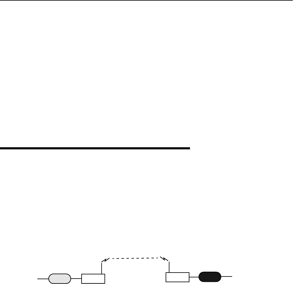
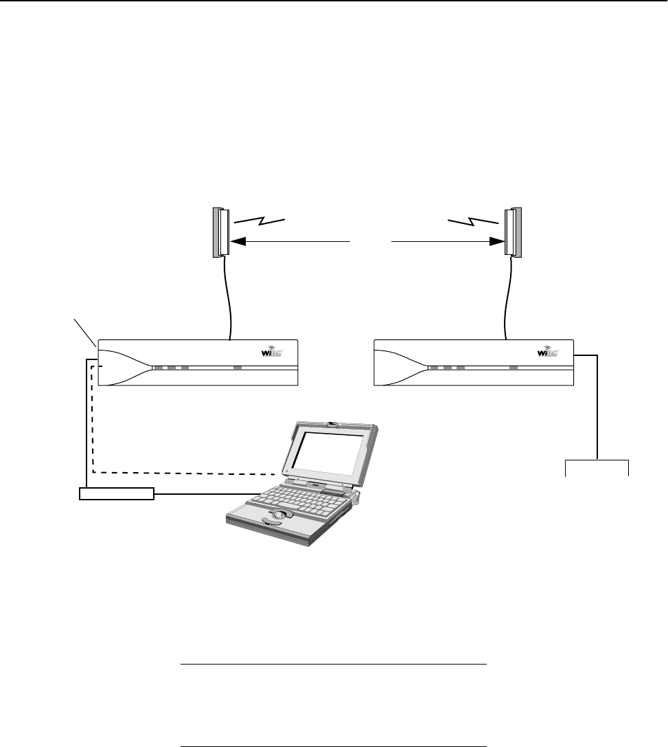
Making a Simple Wireless Bridge
The simplest example of using a AWE 120-58 is a point-to-point wireless bridge that connects two wired
network segments or LANs. Two AWE units are required: a base station and a remote unit.
Point-to-Point Wireless Bridge
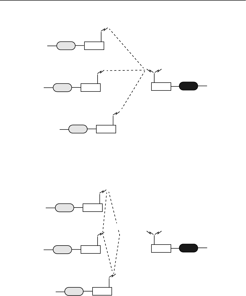
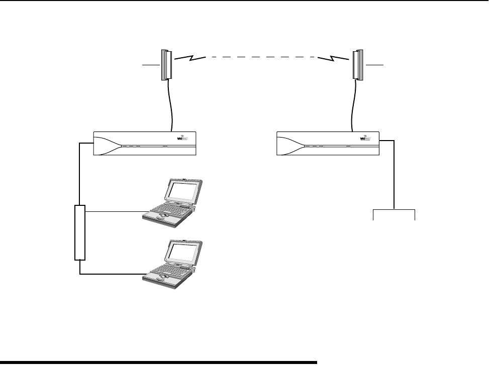
Creating a Simple Wireless Network
You can create a point-to-multipoint wireless network by adding several remote units to a base station. A
base station can support up to 1000 remotes, however, Wi-LAN recommends no more than 225 remotes per
base station to esnure high levels of data throughput. See
Determine the Number of Remotes, page 111 for
more information.
Base
Wired Network
RemoteRouter
Main Wired Network
Router
Hub
Switch
Firewall
Switch
Hub
Firewall
Wireless Link
Description
4 AWE 120-58 Installation & Configuration Guide
Point-to-Multipoint Wireless Network
Direct remote-to-remote communication can occur if a direct RF link can be established between remotes,
and if remotes are in the same RF group.
Remote-to-Remote Communication
Base
RemoteRouter
RemoteRouter
Wired Network
Wired Network
Wired Network
RemoteRouter
Main Wired Network
Router
Hub
Switch
Hub
Switch
Firewall
Firewall
Switch
Hub
Firewall
Switch
Hub
Firewall Wireless Links
Base station polls
Remote Units
Base
Remote
Remote
Remote
Main Wired Network
Remotes must be in the same
RF group to communicate
directly
Wireless Links
Some System Applications
APR 2001 Rev 03 5
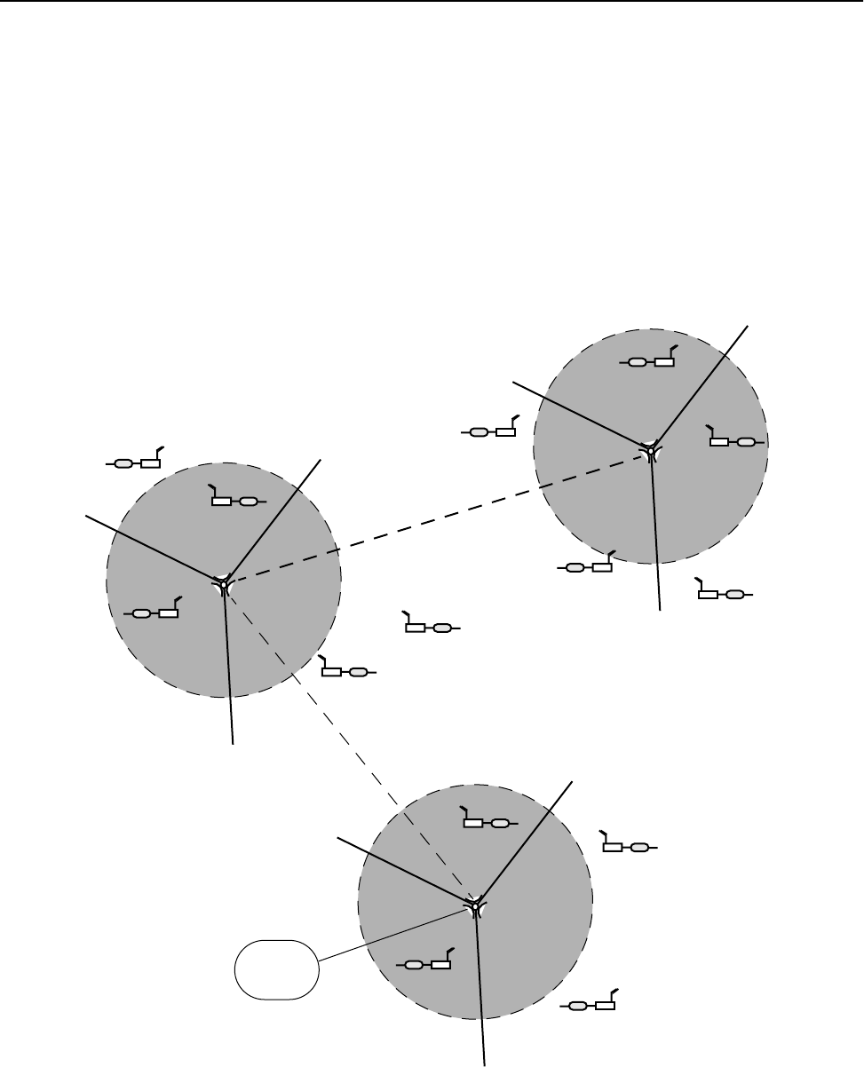
Creating a Network with Cells
Cells or data nodes can be created with AWE units to maxmimize coverage, minimize interference, and
increase data throughput. Directional antennas are mounted on a mast to divide cells into sectors.Each sector
is connected to an antenna and a base station. Directional antennas increase signal gain within the sector and
increase the distance possible between base stations and remotes. Center frequency, acquisition code and
antenna polarization techniques are used to isolate sectors. The increase in data rate depends on the number
of sectors. For example, the data rate of Cell 1 in the diagram below is 36 Mbps (12 Mbps x 3 sectors). Cells
are distributed across a service area and can be linked to each other via a wireless link or a fiber optic cable.
LAN with Cells and Sectors
Fiber Optiic Cable or
Wireless Link
Cell 1
Cell 2
In this example, cells are divided into120 degree sectors.
Cells are linked to other cells by a wired or wireless link.
Remote
Remote
Remote Remote
Remote
Remote
Remote
Remote
Remote
Remote
Base
Stations (3)
Base
Stations (3)
Cell 3
Remote
Remote
Remote
Remote
Base
Stations (3)
Internet
Fiber Optiic Cable or Wireless Link
Description
6 AWE 120-58 Installation & Configuration Guide
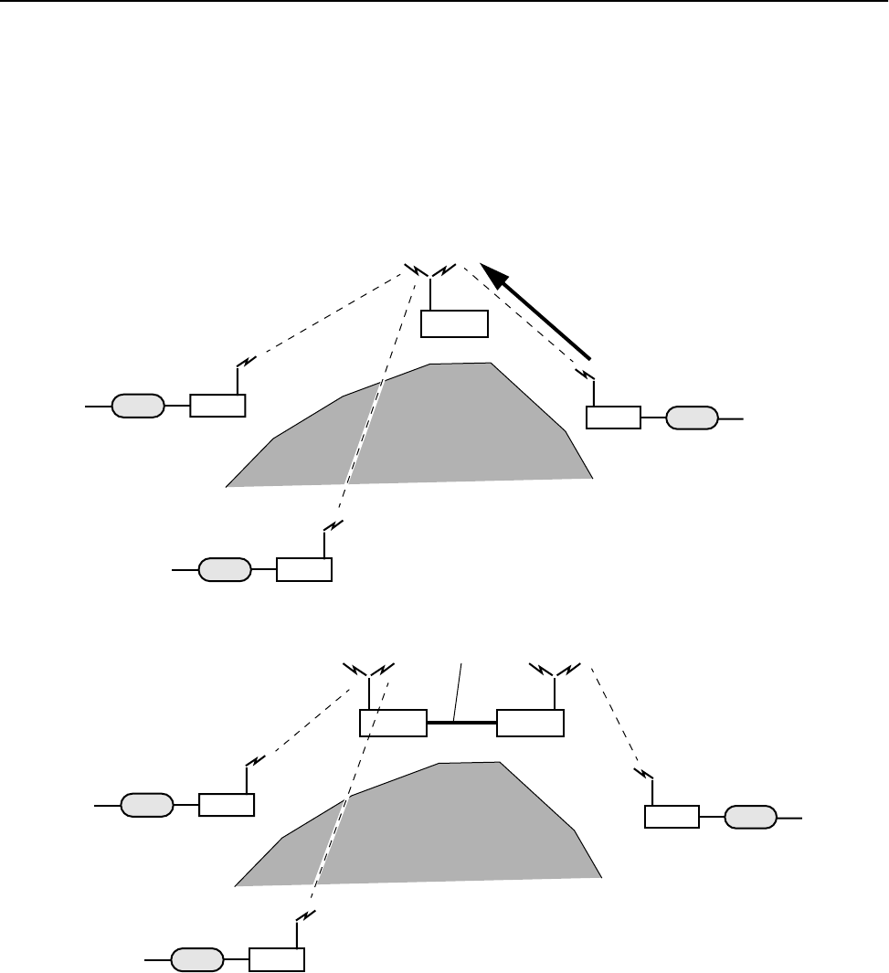
Using a Repeater Base
A base station can function as a repeater to enable wireless data communication around physical obstacles
such as tall buildings or mountains. The repeater passes data around the obstacle to any remote in the same
RF group. The single unit repeater slows data throughput due to the "store and foreward" process where
each packet is handled twice. A dual unit repeater does not slow data throughput.
Base Station as a Repeater
Building a WAN
LAN segments can be linked with AWE units to build a WAN (Wide Area Network). Wi-LAN networks are
installed in many locations around the world. You can contact Wi-LAN for help designing your network.
Remote
Wired Network
Wired Network
Remote
Repeater
Wireless Links
Wired Network
Remote
1
2
3
Mountain
Single Unit Repeater
Dual Unit Repeater
Remote
Wired Network
Wired Network
Remote
Wireless Links
Wired Network
Remote
1
2
3
Mountain
Base Base
Ethernet

Hardware Description
APR 2001 Rev 03 7
Hardware Description
Shipping Package Contents
The shipping package contains the following items.
• AWE unit
• Power supply, table top adapter (12 Vdc)
• Ferrite Block
• Power supply cord
• Installation and Configuration Guide
• Warranty Card
If any of the above items are not included in the AWE 120-58 shipping package, contact Wi-LAN customer
support.
You may also require the following items.
• Bench Test Kit (9000-0034) for unit testing and configuration (kit contains two indoor planar
antennas, test cables, and adapters)
• Cable, straight-through ethernet RJ45, when connecting a unit to a hub
• Cable, crossover ethernet cable RJ45, when connecting directly to the Ethernet port of a PC
• Cable adapter, DB25F to DB9M
• RS-232 DB25 serial cable
You can purchase any of these items directly from Wi-LAN or any authorized supplier. Please contact Wi-
LAN for information about obtaining parts from you local supplier or ordering parts from Wi-LAN.
Description
8 AWE 120-58 Installation & Configuration Guide
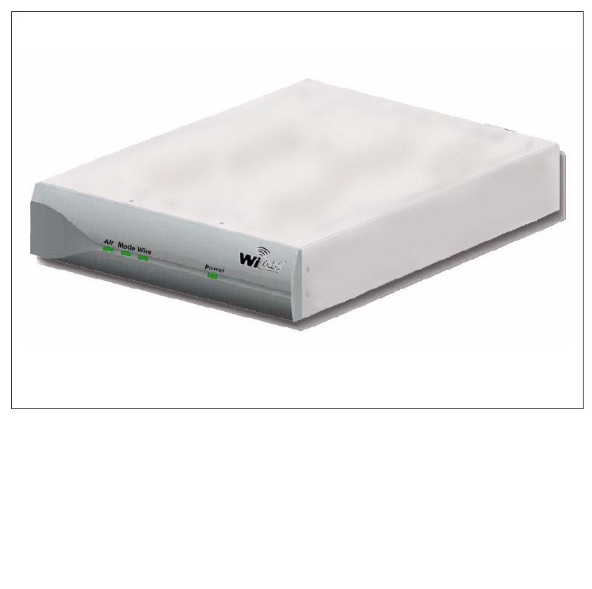
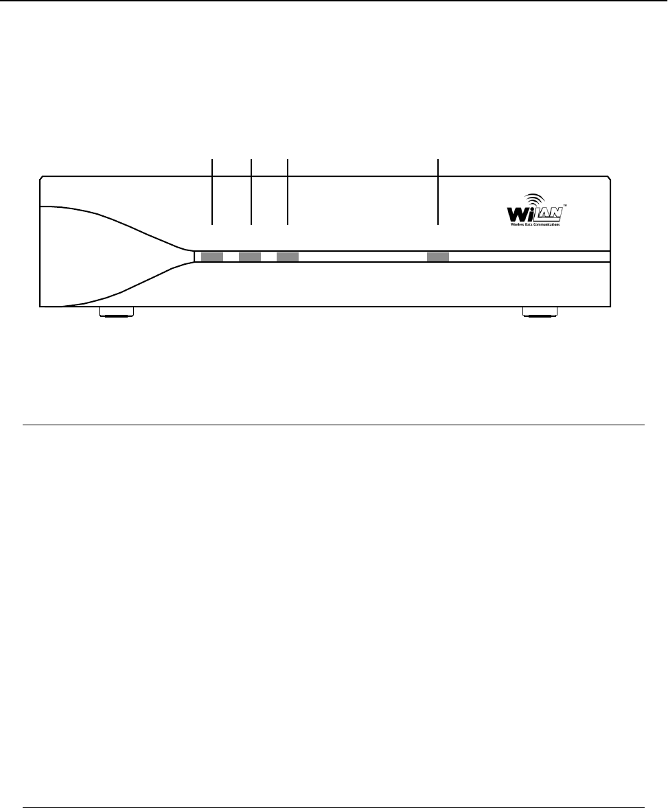
AWE 120-58 Unit
The AWE 120-58 has indicator LEDs on the front panel.
Front Panel
The front panel connector and LEDs are described below. The color of a LED indicates its status. See Front
Panel LEDs, page 149 for detailed information.
Connectors for power, antenna and wired network are located on the rear panel, as well as a mode button
and a Link LED.
Air LED Color of LED indicates the transmit/receive status of the wireless link:
Red = transmitting data to the air
Green = receiving data from the air
Orange = transmitting and receiving approximately equal amounts of
data over the air
Off = listening to the air
Mode LED Color of LED indicates the operating mode of a unit:
Green = Receive Test mode
Red = Transmit Test mode
Orange= RSSI Test mode (measures fade margin, which is indicated by
LED color)
Off = Normal mode
Wire LED Color of LED indicates the transmit/receive status of the wire link:
Green = receiving data from wire
Red = transmitting data to wire
Orange = transmitting and receiving data on the wire
Off = listening to wire or no wire connected
Power LED Green = power is connected to transceiver
Off = no power is connected to transceiver
Air Mode Wire Power
Air Mode Wire Power
Hardware Description
APR 2001 Rev 03 9
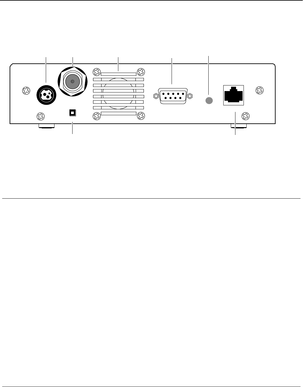
Rear Panel
Items located on the back panel are described below:
Antenna N-type female connector antenna port is located at the top left of the rear
panel. This port should always be connected to an antenna directly or
through a 50 ohm coaxial cable
Serial Port RS-232, DB9 connector used to communicate with a PC. Use this port to
locally configure and test a AWE
Power 3-pin power connector. See DC Power Plug Pinout, page 148 for detailed
pinout illustration
Mode Button Mode button can be used to set the operating mode of a unit without a
terminal. See Setting Operating Mode with the MODE Button, page 97 for
information about the mode button
Ethernet Standard RJ45 female ethernet connector. To connect to a PC Ethernet card,
you must use the crossover twisted-pair cable. To connect to a hub, use a
straight-through twisted-pair cable
Link LED Color of LED indicates the data rate and status of the twisted-pair
connection:
green = 10BaseT link, functioning properly
orange = 100BaseT link, functioning properly
off = No link
Air Vent Air vent for unit’s internal cooling fan
Mode
Power
Antenna
Serial Port Link Ethernet
Antenna
Serial Port
Ethernet
Mode Button
Power Link LED
Air Vent
Port

Description
10 AWE 120-58 Installation & Configuration Guide
AWE 120–58 Specifications
General Specifications
Modulation Method: Multi-Code Direct Sequence Spread Spectrum (MC-DSSS), time
division duplexing (TDD)
Wireless Data Rate: 12 Mbps raw data rate/up to 9 Mbps operational
RF Frequency Range: 5.725 - 5.850 MHz (unlicensed ISM band)
Power Requirements: 12Vdc (via 110/240 VAC 50/60 Hz adaptor)
30W (2.5A) maximum power consumption
Physical: Size: 19.3 x 4.4 x 25.5 centimeters
(7.6 x 1.75 x 10.0 inches)
Weight: 1.49 kg (3.27 lb)
Radio Specifications
Antenna Connector: N-type female
Output Power: +21 dBm to –10 dBm
Receiver Sensitivity: –80 dBm (1 x e–6 BER)
Processing Gain: >10 dB
Center Frequency 5.7410 GHz–5.8338 GHz in 400 kHz steps
Channel Width 33 MHz
Network Support
Packet Format: IEEE 802.3 and Ethernet II
(High-level protocol transparent)
LAN Connection: 10/100BaseT (autonegotiates)
Bridge Functionality: Local Packet Filtering (self-learning)
Static IP address filtering
Dynamic polling of remotes
User configurable data rate (throttling)
Software is upgradeable online via ftp

AWE 120–58 Specifications
APR 2001 Rev 03 11
Wireless Networking
Protocols
Network Topologies: Point-to-Point, Point-to-Multipoint, Multipoint-to-Multipoint
Repeater Mode: User Configurable
Private Network User configurable using repeater and RF Group
RF Collision Management: Dynamic Polling with Dynamic Time Allocation
Security
Data Scrambling: User Configurable
Data Security Password: Security password of up to 20 bytes in length
(1048 combinations)
Configuration, Management, and Diagnostics
Configuration Methods: SNMP, telnet and RS-232 Serial Port
SNMP: Version I compliant (RFC 1157), MIB standard and enterprise
(RFC 1213)
Management Port Functionality: Supports system configuration, security, access control,
wireless LAN diagnostics and management, menu-driven
ASCII interface via RS-232 DB-9 connector
Environment
Units must be operated in a weatherproof environment with
an ambient temperature from 0 to 40º Celsius and
humidity 0 – 95% non-condensing

Description
12 AWE 120-58 Installation & Configuration Guide
APR 2001 Rev 03 13
Installation
Overview
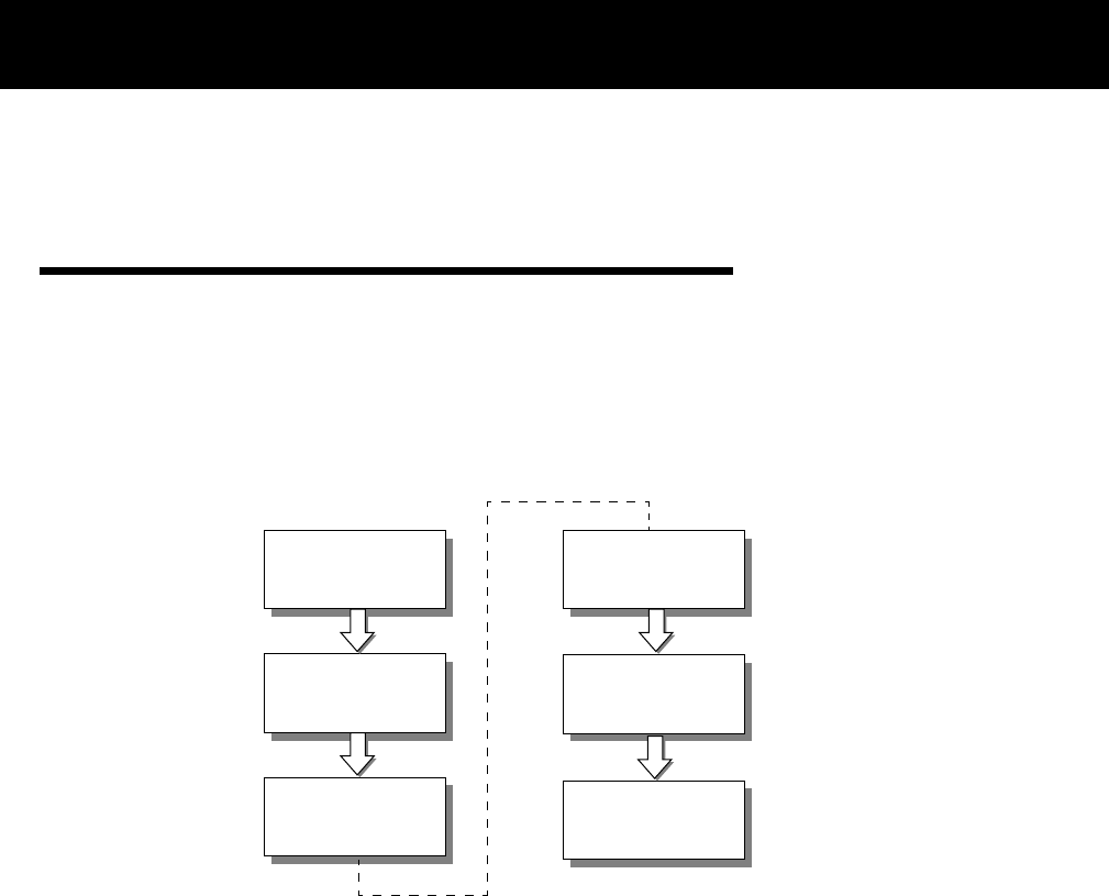
This section explains how to install AWE units. You will first assemble, configure and test units in a controlled
environment so that any problems can be solved easily, and then install units in the field. By going through this
process, you will ensure a successful installation, save time spent on-site, and reduce travel from site to site.
The following basic process should be followed.
1. Obtain the network plan, equipment and tools.
2. Assemble units.
—Check the contents of each AWE shipping package to ensure that you have received the required parts.
—Connect an indoor antenna or dummy load, connect the power supply unit and check the power.
3. Pre-configure units—Configure units according to the network plan.
4. Bench test units—Test basic RF and network operation of units in a controlled environment.
5. Install units—Place the tested units in their field locations and connect them to antennas, the wired
network, and power. Install the ferrite block around the 10/100BaseT Ethernet cable.
6. Test Network—Test the operation of the installed network.
Obtain
Assemble
Pre-Configure
Install
1
2
3
5
Network Plan
Test
6
Bench Test
4
Units
Units
Units
Units
Network

Installation
14 AWE 120-58 Installation & Configuration Guide
Obtain Network Plan
The network plan describes the network in detail, including the following:
• Type and number of units
• Physical layout
• Configuration settings for each unit
• Site names, IP addresses and links
• Antenna types, RF cables and cable lengths, surge suppressors, terminators
• Network cable types and lengths
• Grounding kits and backup power requirements
• Link budget
• Floor plans and equipment cabinet requirements.
The network plan must be completed before any equipment is installed. See Appendix A: Planning Your Wireless
Link, page 111 for more information about network plans.
Check your equipment and tools: Ensure that you have all the required parts and equipment specified in
the network plan. You will require a Bench Test Kit (9000-0034) and some tools to install and configure units–
in addition to a standard tool kit, you will require a laptop PC with HyperTerminal® or other terminal
emulation software and RS-232 cable. You may require a spectrum analyzer, Site Master® communication test
set, digital multimeter, 2-way radios, binoculars, strobe lights, ladder, and weatherproof caulking.
Assemble Units
Checking the Shipping Contents
Check the contents of each AWE shipping package to ensure that you have received all the materials. See
Shipping Package Contents, page 7 for a list.
Assembling AWE Units
➧ To assemble a unit
1. Connect an indoor antenna (included with Bench Test Kit) to the antenna port at the back of the unit.
Important
An indoor antenna is required for each unit for testing and configuration
purposes. Indoor antennas must be separated by at least 2 m.
Indoor antenna may differ from illustration.
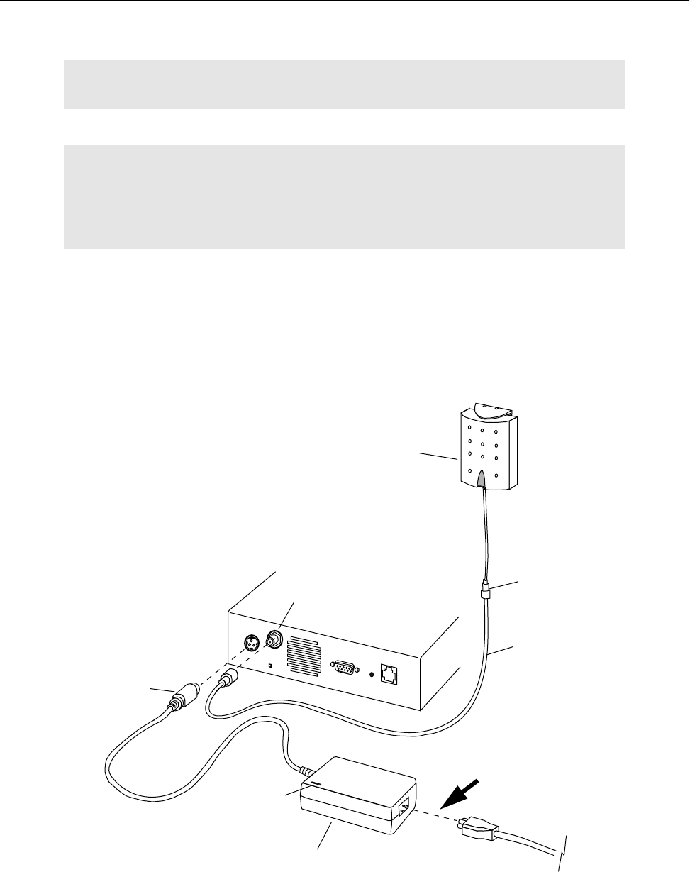
Assemble Units
APR 2001 Rev 03 15
2. Connect the power supply unit to the Power connector at the back of the unit. The AWE 120-58 must be
connected only to a Wi-LAN approved power supply unit with an output of 12 Vdc. See DC Power Plug
Pinout, page 150 for pinout information.
Antenna and Power Connections
Important
Antennas must be installed by a knowedgeable and professional installer.
WARNING
Never operate a unit without an antenna, dummy load, or terminator
connected to the antenna port.
Operating a unit without an antenna, dummy load, or terminator connected
to the antenna port can permanently damage a unit.
Power Supply Unit
AC Power Cord
DC Power
Plug
12 Vdc
Antenna port
Hint: To turn unit
power ON or OFF,
connect or
cord here.
disconnect the power
Power LED
Coaxial
Cable
Indoor
Antenna
SMA to N-type
Adaptor

Installation
16 AWE 120-58 Installation & Configuration Guide
Checking the Power
➧ To check the power
1. Plug the AC power cord into the AC power outlet.
2. Plug the DC power plug (12 Vdc) to the unit’s power connector.
3. Plug the AC power cord into the power supply unit.
The green Power LED on the front of the unit turns ON and the Air, Mode and Wire LEDs turn ON
briefly then turn OFF.
The green Power LED stays ON. The Mode LED stays OFF (indicating Normal mode). The Air LED is
orange, green, red or OFF. See Front Panel LEDs, page 149 for more information about LEDs.
If the green Power LED does not turn ON, check your AC power source and the power supply unit. Measure
the power supply unit voltage at the DC Power Plug between pins 1 and 2. See DC Power Plug Pinout, page 150.
The output should be 12 Vdc and the power supply unit power LED should be ON.
Pre-Configure Units
This section describes how to pre-configure a base station and a remote unit, which are the basic units
required for a point-to-point wireless link. Once you have configured and tested this basic equipment, you
can configure and test all remaining units. See Configuration, page 33 for detailed information about
configuration settings.
Configuring a Base Station
When you configure a unit as a base station, you need to perform the following tasks.
• Check the Network Configuration information of the unit.
• Set the Station Type of the unit to "Base Station"
• Assign the Station Rank (# equal to or greater than the number of remote units)
• Choose a Center Frequency (must be the same for all units in network)
• Select an Acquistion Code (must be the same for all units in network)
• Set Tx Power Level Adjust intially to "0 dB"
• Set the security passwords (must be the same for all units in network)
• Change the default menu passwords
These tasks are described below in detail.
➧ To configure a unit as a base station
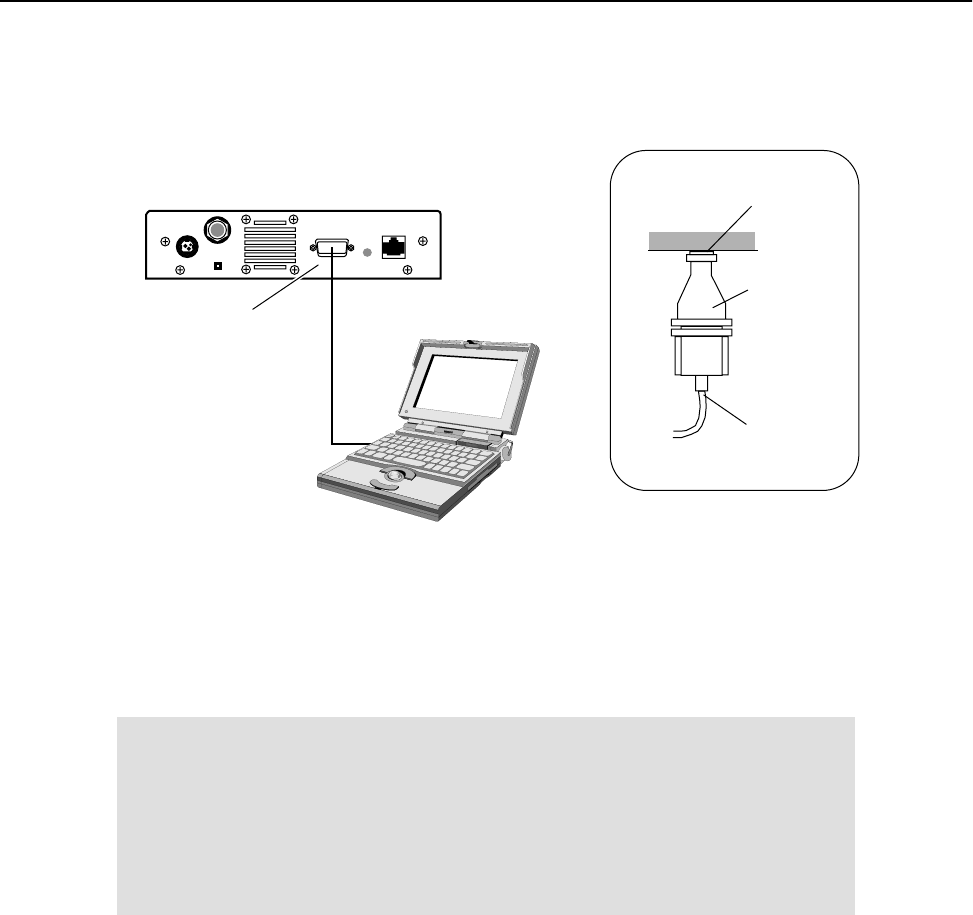
1. Connect a PC to the AWE unit that will be the base station. Connect the COM port of the PC to the
serial port of the AWE with the adapter plug and straight through RS-232 cable.
Pre-Configure Units
APR 2001 Rev 03 17
Connecting PC to Serial Port
2. Start HyperTerminal® (see Appendix B: Using HyperTerminal, page 125 for details) or another terminal
emulation program such as Tera Term™. Use the following communication settings: 9600 bps, 8 bits, no
parity, 1 stop bit, no flow control.
3. Press Enter. The AWE 120-58 Login window is displayed.
4. Type the default password (supervisor) and press Enter. The Main Menu is displayed.
Note: supervisor enables you to change the configuration settings with the Main Menu. See Setting Menu
Passwords, page 87 for more information about menu passwords.
AWE Unit
PC
RS-232 Serial Cable
to PC COM port
Serial Port
RS 232 Serial
Cable to
RS-232
Adapter
Serial
Port (DB9)
(See detail)
Detail
PC COM port
AWE
DB 25 to 9 pin
Wi-LAN AWE 120-58 Login
Software: Rev 0.0.0 (Aug 25 2000 10:13:37)
Hardware: Rev 0.0.0 (4MB SDRAM, 4MB Intel Flash)
Enter Password:
Installation
18 AWE 120-58 Installation & Configuration Guide
Main Menu
5. Select Network Configuration. Check the network configuration information, the IP address and
subnet mask settings. If necessary, change settings to match the network plan.
6. From the Main Menu, select Radio Module Configuration and press Enter. The Radio Module
Configuration window is displayed.
• Select Station Type. Choose Base Station.
Wi-LAN AWE 120-58 Main Menu
-> Unit Identification
Hardware/Software Revision
System Software ROM Images
Current System Status
Network Configuration
IP Filter Configuration
RF Station Configuration
Radio Module Configuration
RF/Ethernet Statistics
System Security
System Commands
Link Monitor Display
Logout
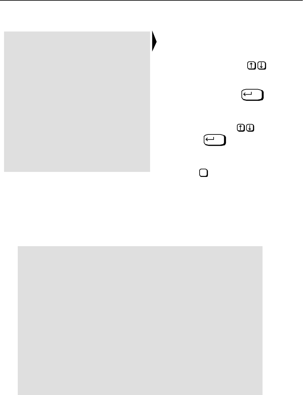
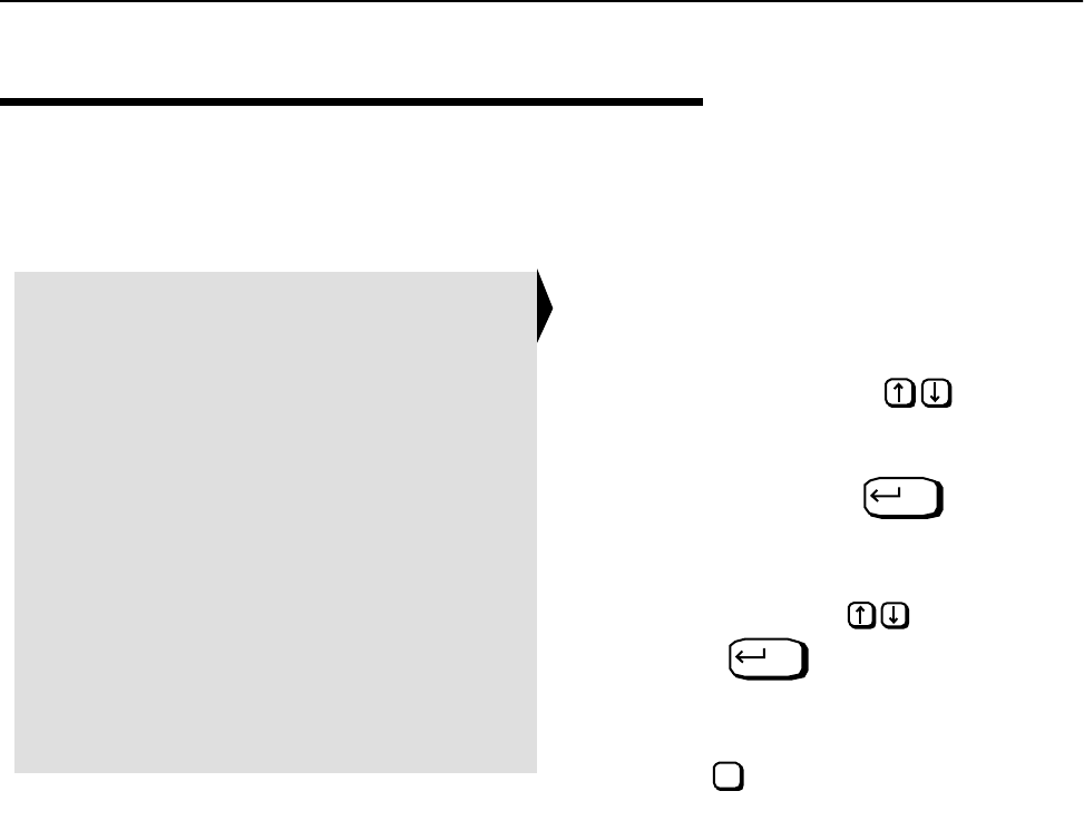
How to Use the Main Menu
• To select an item from the Main
Menu or a sub-menu, press the
keyboard arrow keys to
move the cursor –> next to the
item.
Press the Enter key to
open the data entry field.
• To scroll through items in the data
entry field, press .
Press to select an item
from the field.
• To exit from a menu, press the Esc
key.
Enter
Enter
Esc
Radio Module Configuration
New Current Flash
Station Type -> Remote Unit Remote Unit Remote Unit
Station Rank (1-1000) 1 1 1
Center Frequency (57410-58338) 5.7874 GHz 5.7874 GHz 5.7874 GHz
Security Password 1 (Hex) 1 1 1
Security Password 2 (Hex) 10 10 10
Security Password 3 (Hex) 100 100 100
Security Password 4 (Hex) 1000 1000 1000
Security Password 5 (Hex) 10000 10000 10000
Scrambling Code (Hex) 0 0 0
Acquisition Code (0-15) 1 1 1
Config Test Minutes (1-120) 30 30 30
Tx Power Level Adjust 0 dB 0 dB 0 dB
Base Station Only Parameters
Repeater Mode off off off
System Symmetry Type Asymmetric Asymmetric Asymmetric
Dynamic Polling Level (1-100) 1 1 1
Remote Station Only Parameters
Remote Unit RF Group (0-63) 0 0 0
Reboot New RF configuration Press Enter to Execute
Save Current Config to Flash Press Enter to Execute

Pre-Configure Units
APR 2001 Rev 03 19
• Select Station Rank. Enter the total number of remote units in your wireless network. For
example, if you have only one remote unit, enter "1". If there are 20 remote units, enter "20".
• Choose a Center Frequency. Enter the value of the center frequency (range is 57410–58338
in 400 kHz steps). All wireless units must be set to the same center frequency.
• Select Security Password x. Type security passwords in hexadecimal for the unit. All units in
the same network must have the same set of security passwords.
• Select Scrambling Code. Enter a hexadecimal value or leave the default at "0". All units in the
same network must have the same scambling code.
• Select Acquistion Code. Enter a value from 0–15. (All units in the same network must have
the same acquisiton code.)
• Select Config Test Minutes. Enter a time in minutes, for example, 10. The unit will automat-
ically reboot when this time period expires, and uses the settings stored in flash memory instead of
current settings.
• Select Tx Power Level Adjust. Choose an initial value of 0 dB, which means no Tx power
attenuation.
• Select Reboot New RF configuration and press Enter. The unit reboots and the Login
window is displayed.
7. Log in to the unit. (Type supervisor for the password). The Main Menu is displayed.
8. Select Radio Module Configuration and press Enter. The Radio Module Configuration window
is displayed.
• Select Save Current Config to Flash and press Enter. The new settings are stored in flash
memory and displayed on the menu. The word appears on the screen.
9. Press Esc to go back to the Main Menu.
10. Select Logout to exit or press Esc.
Note: At this time you may want to finish configuring the base station according to the network plan. See
Configuration, page 33 for instructions about viewing and changing various settings.
Configuring a Remote Unit
When you configure a unit as a remote unit, you need to do the following tasks.
• Check the Network Configuration information of the unit
• Set the Station Type of the unit to "Remote Unit"
• Assign the Station Rank (polling ID # of the remote unit)
• Select a Center Frequency (must be the same for all units in network)
• Select an Acquistion Code (must be the same for all units in network)
• Set Tx Power Level Adjust intially to "0 dB"
• Set the security passwords (must be the same for all units in network)
• Change the default menu passwords
These tasks are described below in detail.
Success

Installation
20 AWE 120-58 Installation & Configuration Guide
➧ To configure a unit as a remote unit
1. Connect a PC to a AWE remote unit. Connect the COM port of the PC to the Serial port of the remote
unit using an adapter plug and RS-232 cable. See Configuring a Base Station, page 16 for cabling diagram.
2. Start HyperTerminal® or other terminal emulation program (see Appendix B: Using HyperTerminal, page
125). Use the following commnication settings: 9600 bps, 8 bits, no parity, 1 stop bit, no flow control.
3. Press Enter. The AWE 120-58 Login window is displayed.
4. Type the default password supervisor and press Enter. The Main Menu is displayed.
5. Select Network Configuration. Check the IP settings. If necessary, change the settings to match
the network plan.
6. From the Main Menu, select Radio Module Configuration and press Enter. The Radio Module
Configuration window is displayed.
• Select Station Type. Choose Remote Unit.
• Select Station Rank. Enter the rank number of the remote unit. Enter a number from 1–1000.
• Choose a Center Frequency. Enter the value of the center frequency (range is 57410–58338
in 400 kHz steps). All wireless units must be set to the same center frequency.
• Select Security Password x. Type security passwords in hexadecimal for the unit. All units in
the same network must have the same set of security passwords.
• Select Scrambling Code. Enter a hexadecimal value or leave the default at "0". All units in the
same network must have the same scambling code.
• Select Acquistion Code. Enter a value from 0–15. (All units in the same network must have
the same acquisiton code.)
• Select Config Test Minutes. Enter a time in minutes, for example, 10. The unit will automat-
ically reboot when this time period expires, and uses the settings stored in flash memory instead of
current settings.
Radio Module Configuration
New Current Flash
Station Type -> Remote Unit Remote Unit Remote Unit
Station Rank (1-1000) 1 1 1
Center Frequency (57410-58338) 5.7874 GHz 5.7874 GHz 5.7874 GHz
Security Password 1 (Hex) 1 1 1
Security Password 2 (Hex) 10 10 10
Security Password 3 (Hex) 100 100 100
Security Password 4 (Hex) 1000 1000 1000
Security Password 5 (Hex) 10000 10000 10000
Scrambling Code (Hex) 0 0 0
Acquisition Code (0-15) 1 1 1
Config Test Minutes (1-120) 30 30 30
Tx Power Level Adjust 0 dB 0 dB 0 dB
Base Station Only Parameters
Repeater Mode off off off
System Symmetry Type Asymmetric Asymmetric Asymmetric
Dynamic Polling Level (1-100) 1 1 1
Remote Station Only Parameters
Remote Unit RF Group (0-63) 0 0 0
Reboot New RF configuration Press Enter to Execute
Save Current Config to Flash Press Enter to Execute

Bench Test Units
APR 2001 Rev 03 21
• Select Tx Power Level Adjust. Choose an initial value of 0 dB, which means no Tx power
attenuation.
• Select Remote Unit RF Group. Enter a value from 0–63. (For testing purposes, you may leave
the value = 0.)
• Select Reboot New RF configuration and press Enter. The unit reboots and the Login
window is displayed.
7. Log in to the unit. (Type supervisor for the password). The Main Menu is displayed.
8. Select Radio Module Configuration and press Enter. The Radio Module Configuration window
is displayed. The settings under Current change to values that were in the New column.
9. Select Save Current Config to Flash and press Enter. The new settings are stored in flash
memory and displayed on the menu. The word appears on the screen.
10. Press Esc to go back to the Main Menu.
11. Select Logout to exit or press Esc.
Note: At this time you may want finish configuring the unit according to the network plan. See Configuration,
page 33 for instructions about viewing and changing various settings.
Bench Test Units
In this section, you will perform the following tasks:
• Ensure that a basic RF link exists between a base station and a remote unit.
• Test the basic link with Link Monitor and adjust Tx power level.
• Perform some simple network tests.
Establishing a Basic RF Link
This test ensures that a basic RF link exists between a base station and a remote unit.
Tip: First configure one unit as a base station, and then use it to test all the remote units.
To establish a basic RF link
1. Ensure that one unit is configured to a base station, select a center frequency and set the test minutes.
See Configuring a Base Station, page 16.
2. Ensure that the other unit(s) are configured as remote units with the center frequency the same as the
base station. See Configuring a Remote Unit, page 19.
IMPORTANT
The quality of your digital data transmission depends greatly on the quality of your RF
link. Always try to establish a high-quality RF link first. A high-quality RF link will
result in high-quality data transmissions and a low BER. A low-quality RF link will result
in low-quality data transmissions and a high bit error rate (BER). Digital data can always
be sent across a high-quality RF link. If the RF link is of poor quality, data either cannot
be sent at all or will contain too many errors to be useful..
Success
Installation
22 AWE 120-58 Installation & Configuration Guide
3. Place the base station and a remote unit at least two meters apart with a clear line of sight between
antennas. Point the antennas toward each other.
Basic Test Setup
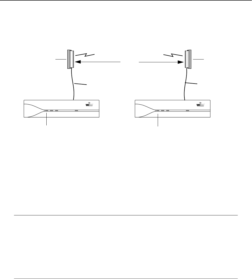
4. Power up the base station. The green Power LED is ON. The Air LED of the base unit is red. This Air LED
color indicates that the unit is transmitting data but is not receiving a response. (The reason is that the
remote is powered off.)
5. Power up the remote unit. The green Power LED is ON. The Air LED of the remote unit turns orange
and the Air LED of the base station also turns orange as both units send and receive data from each
other. Orange is the normal Air LED color.
The color of the Air LED during this step indicates the following conditions.
Note: If antennas are placed too close together, the strong transmit signal will saturate the receiving unit.
Fine-tune antennas by changing antenna orientations until the Air LED is orange.
Next, you will test the link with the Link Monitor test and adjust the Tx power level to obtain a fade margin
of 15–30 dB. .
Orange (both stations) Units are continuously sending and receiving sync packets
Red (base station) Stations are configured incorrectly, and the base station is
transmitting without receiving acknowledgment
Green (remote station) Stations are configured incorrectly, and the remote station is
receiving packets to which it cannot respond
Off Nothing is being received (by the remote) or transmitted (from the
base)
2 m
minimum
Air LED = orange
Base Unit Remote Unit
Air LED = orange
Indoor
Antenna
Indoor
Antenna
Air Mode Wire Power Air Mode Wire Power
Coax Adapter Cable
Coax Adapter Cable

Bench Test Units
APR 2001 Rev 03 23
Testing the Link and Adjusting Tx Power
A basic RF link is established when the base station and remote unit can receive and transmit data to each
another (indicated by orange Air LEDs on both units). Once you have established a basic RF link, you test the
link by running the Link Monitor test and viewing the link statistics. Finally, you adjust the Tx Power of the
base and remote units to obtain a 15–30 dB fade margin.
➧ To test the RF link and adjust Tx power
1. Connect the test PC to the serial port of the base station or remote unit. See Connecting PC to Serial Port,
page 17.
2. Log in to the unit and go to the Main Menu.
3. Select RF Station Configuration and press Enter. The RF Station Configuration window is
displayed.
• Select Operating Mode. Press the arrow keys to select Normal mode.
• Select RF Transmit Status. Select unblocked.
• Select Link Monitor Remote Station Rank. Enter the rank of the unit that you want to
link test. (The rank is the identification number of the unit. The rank of a remote can be any num-
ber from 1 – 1000. The rank number of the the base station is always 0. See Setting the Station Rank,
page 69.)
• Select Link Monitor Period. Enter a link monitor period of 1. (A value of 1 means that 50%
of available data packets will carry test data. The higher the period number, the fewer the number
of data packets that will carry test data. See Setting the Link Monitor Period, page 61 for more infor-
mation.) The Link Monitor test starts as soon as a non-zero value is entered in the field.
Next, you view the link statistics and adjust Tx power level.
RF Station Configuration
Operating Mode -> Normal Mode
RF Transmit Status unblocked
Link Monitor Period (0=OFF, 1-10000) 0
Test Mode Timer Minutes (1-1000) 5
Base Station Only Parameters
Maximum Remote Distance 5 Km
Link Monitor Remote Station Rank 1
Remote Station Only Parameters
Throttle Enable off
Throttle Level (1-50) 1

Installation
24 AWE 120-58 Installation & Configuration Guide
4. From the Main Menu select Link Monitor Display and press Enter. The RF Background Link
Monitor Statistics window is displayed.
5. Check for the following statistics:
• Base to Remote BER = 0.0E+00
• Remote to Base BER = 0.0E+00
• Base to Remote Corr Power between 15 – 50 dB
• Remote to Base Corr Power between 15 – 50 dB
If the Corr Power is <15 dB the receive signal is probably too weak to be useful. If the power is
>55 dB the receiving unit is probably being saturated.
6. Adjust Tx power of both units to obtain a fade margin (Corr Power) of 15–30 dB, as displayed by the Link
Monitor Statistics window. See Adjusting the Tx Power Level, page 76 and Performing Transmit and Receive
Tests, page 57.
7. When you are finished viewing link monitor statistics, disable Link Monitor to remove the overhead test
data from the wireless link. To disable Link Monitor, select
RF Station Configuration from the Main Menu and press Enter. The RF Station Configuration
window is displayed.
8. Select Link Monitor Period and press Enter. The field is highlighted.
9. Type 0 in the field and press Enter. The link monitor test ends.
10. Press Esc to exit.
You have now established an RF link between two units, tested the ability of the link to carry test data, and
adjusted the Tx power level to 15–30 dB. Next, you connect the units to a network and perform some simple
network tests.
RF Background Link Monitor Statistics
Link Monitor Rank 1
Base to Remote BER 0.0E+00
Remote to Base BER 0.0E+00
Missed Packet Count 0
Base to Remote Env Power 27
Base to Remote Corr Power 28
Remote to Base Env Power 29
Remote to Base Corr Power 30
Bench Test Units
APR 2001 Rev 03 25
Performing Simple Network Tests
To test units within a simple network you require two AWE 120-58 units, a LAN connection, a PC and a
crossover ethernet cable or hub connection. A ferrite block is placed around the 10/100BaseT Ethernet cable
to prevent electromagnetic interference (EMI) from transferring from a unit to the Ethernet cable, and from
the Ethernet cable to the unit. The ferrite block is included with the contents of the shipping box. Install a
ferrite block when testing units, and ensure that a ferrite block is in place when units are installed in the field.
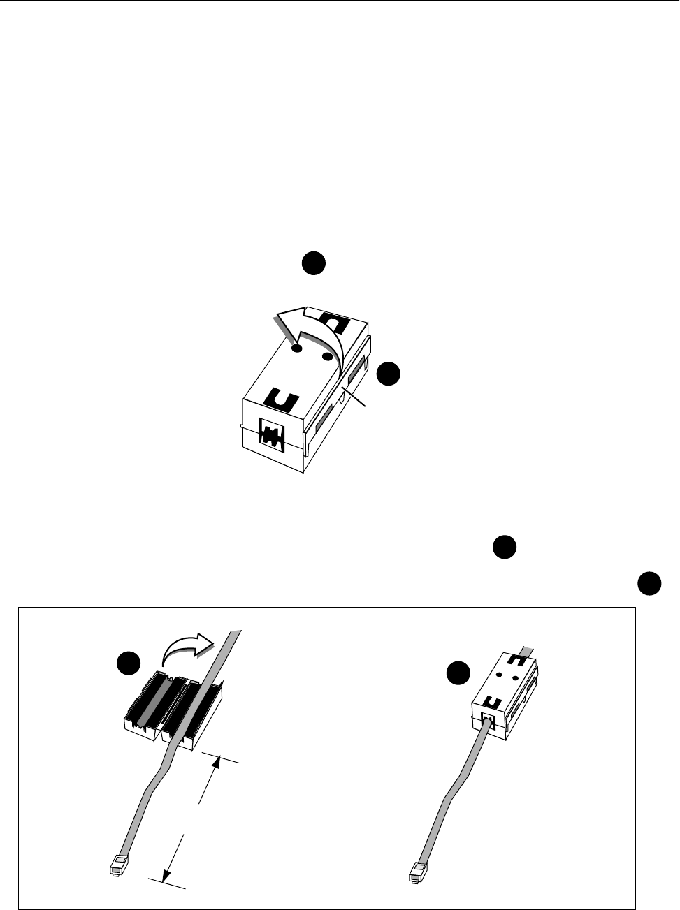
➧ To install the ferrite block
1. Remove the ferrite block from the plastic packaging.
2. Pull the clip and open the ferrite block. See
3. Place the Ethernet cable in the center of the open ferrite block. Locate the block approximately 4 cm
from the cable connector end that plugs into the unit’s Ethernet port. See
4. Close the ferrite block around the Ethernet cable, making sure that the block snaps together. See
1
Clip
1
Ferrite Block
2
3
2
4
4 cm
3
Installation
26 AWE 120-58 Installation & Configuration Guide
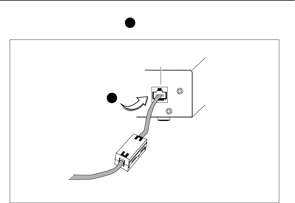
5. Plug the Ethernet cable into the unit. See 4
Ethernet
Ethernet port
4
Bench Test Units
APR 2001 Rev 03 27
➧ To perform a simple network test
1. Connect the Ethernet port of the base station to the internet port of the PC. You can either connect to
a network hub or connect directly using an RJ45 crossover ethernet cable.
Simple Network Test Setup
2. Power up both AWE units. Initially the LEDs should appear as follows.
3. Configure the AWE units within your network. See Network Configuration, page 42 for information about
AWE Internet addresses. See Appendix C: Configuring a Simple Data Network, page 127 for information
about configuring simple peer-to-peer networks.
4. Create some network traffic to test the wireless link. For example, use ping or ftp put and get to
transfer a large test files, in both directions, across the link. The Wire LED on the AWE indicates link file
transfer activity to the wired LAN. When the file transfer is done, ftp displays the size of the file and the
time it took to transfer the file. This information can be used to measure the data throughput of the
wireless link, and is very useful for troubleshooting.
Power LED Green
Mode LED Off
Air LED Orange
Base Unit
PC
LAN
10/100 BaseT HUB
10/100 BaseT Cable
Direct 10/100 BaseT Cable (Crossover)
Cable connects to
Ethernet port
(Straight
Through)
Cable
10/100 BaseT
Air Mode Wire Power Air Mode Wire Power
2 m
minimum

Installation
28 AWE 120-58 Installation & Configuration Guide
5. Test all units in the network.
ping
ftp
Using ping and ftp
From the command line prompt, type:
C:> ping IP Address
To connect to the node, from the DOS prompt, type:
C:> ftp IP Address
Example:
ping 192.163.2.88
Follow the instructions.
ftp> help
For instructions about using ftp, type "help"
at the ftp prompt.

Install Units
APR 2001 Rev 03 29
Install Units
This section provides some guidelines about installing units in the field.
• Install the units at locations identified in the network plan.
• Verify that there is no interference at the site by performing spectrum sweeps with a spectrum
analyzer. Perform sweeps at various times of the day (for example, 9AM, noon, and 3 PM are peak
telephone traffic times.) If there are problems, contact the network planner, who may need to change
the system configuration or design.
• Sweep antennas and cables with the Site Master® communications test set before securing antennas
and cables to towers, while they are on the ground and easy to access. Sweeping helps to ensure that
antennas and cables will operate as expected.
• Initially install equipment with flexibility—do not tie down cables, antennas should be free to move,
allow some slack in cables, avoid drilling and do not seal connections.
• Align antennas. (Two people are required, one at the base station and one at the remote unit. When
in the field, you may require binoculars and 2-way radios to communicate.) When aligning antennas,
adjust the orientation of the remote antenna while running a link monitor test between the remote
and the base station. Adjust the antenna until you achieve the highest fade margin with no bit errors
(BER = 0). See Performing the RSSI Test, page 59 and Performing Link Monitor Test (Normal Mode), page 54
for instructions. Repeat the antenna alignment procedure for each remote.
• When antennas are aligned and cables are secured, sweep the antennas with the Site Master test set
a final time before connecting to AWE.
• Install ferrite blocks on all 10/100BaseT Ethernet cables at the end of the cable that plugs into the
unit. See Performing Simple Network Tests, page 25.
• Perform diagnostic tests on the installed system. Compare field results to bench test results using
ping, ftp, fade margins, etc. Document your results (these results will be very useful when
troubleshooting and monitoring the system’s performance).
• When the system works as specified in the network plan, lock down and weatherproof all equipment
and connnections.
WARNING
All antennas must be professionally installed following accepted safety, grounding,
electrical, and civil engineering standards. An antenna (indoor or outdoor), dummy load,
or terminator must be connected to the antenna port of a unit before a unit is powered
up to avoid damaging the unit.

Installation
30 AWE 120-58 Installation & Configuration Guide
Point-to-Multipoint Installation
The procedure for installing a point-to-mulitpoint system is the same as the procedure for installing a point-
to-point system. Treat each link in a point-to-multipoint system as a single, point-to-point wireless link.
Co-Location Installation
When you install a system with sectors and co-located base stations (see Creating a Network with Cells, page 5
for an example), you install and test sectors as if they were point-to-point systems; however, in this case you
must ensure that individual sectors are not interfering with each other.
• Align and test the first sector. Measure the fade margin and run the link monitor test. Document your
results, then turn off the radio in the first sector.
• Align and test the second sector. Measure the fade margin and run the link monitor test. Leave the
link monitor test running in the second sector.
• Turn on the radio in the first sector again and run the continuous tranmit test. See Performing Transmit
and Receive Tests, page 57.
• Observe the BER and fade margin of the second sector radio. Look for changes to determine if the
first sector is interfering with the second sector.
• Repeat the tests for all sector/pair combinations.
Test Network
Run the link monitor test and other tests such as ping and ftp file transfers to verify network operation when
the units are installed in the field. See Performing Link Monitor Test (Normal Mode), page 54.
Adding to a Network
Always add to your network one link or device at a time, working from a known base network. Measure and
document changes to the system and changes in performance. For example, you can transfer files with ftp
and measure the performance with LAN analyzer software. The key to a successful network is to proceed
one step at a time and to understand your network!
Preventative Maintenance and Monitoring
APR 2001 Rev 03 31
Network Test Setup
Preventative Maintenance
and Monitoring
You should set up a preventative maintenance schedule for your network. Wi-LAN recommends that the
following preventative maintenance be performed at least semi-annually.
• Regularly run link monitor tests across the network and measure BER and fade margin. You can also
test the network with ping, ftp and file transfers. Other resources are available on the Internet that
can help you monitor the performance of your link.
• If you have SNMP application software, you can check unit operation from a remote location. See
Appendix D: SNMP, page 133 for more information.
If you have SNMP application software, you can check unit operation remotely. See Appendix D: SNMP, page
133 for more information.
You should periodically perform a physical inspection of each site.
• Check that antennas and cables are secure and have not become loose.
• Check for physical obstructions in the line-of-sight radio path, such as trees and buildings.
• Sweep antennas and cables to ensure that antennas and cables are intact and operating properly.
• Check that there are no water leaks in cabinets.
• Check weatherproofing.
• Check for new sources of electromagnetic interference.
Indoor
Antenna
Indoor
Antenna
Base Unit Remote Unit
LAN
10/100 BaseT HUB
PC with LAN analyzer software
PC
Air Mode Wire Power Air Mode Wire Power

Installation
32 AWE 120-58 Installation & Configuration Guide

APR 2001 Rev 03 33
Configuration
Overview
This section explains how to use the Main Menu to configure and test your AWE unit, and to obtain useful
statistical and maintenance information.
Main Menu
In this section, each item in the Main Menu is described in the order that it appears in the menu. See Appendix
F: Menu Map, page 151 for a complete listing of submenus. Use the Main Menu and your keyboard keys to
select, view or change settings. Some items in the menu simply display information, while others ask you to
enter data or make a selection from a list.
Main Menu
Wi-LAN AWE 120-58 Main Menu
-> Unit Identification
Hardware/Software Revision
System Software ROM Images
Current System Status
Network Configuration
IP Filter Configuration
RF Station Configuration
Radio Module Configuration
RF/Ethernet Statistics
System Security
System Commands
Link Monitor Display
Logout

Configuration
34 AWE 120-58 Installation & Configuration Guide
Accessing the Main Menu
You can access the Main Menu of a AWE unit with a HyperTerminal® session (via the Serial port) or a telnet
session. Most instructions provided in this chapter assume that you have opened a HyperTerminal session.
You can also configure the AWE 120-58 remotely with the SNMP (Simple Network Management Protocol).
See Appendix D: SNMP, page 133 for information about SNMP.
Accessing the Main Menu with HyperTerminal®
➧ To access the Main Menu with HyperTerminal
1. Disconnect power from the AWE unit.
2. Connect a serial cable from a DB9 serial port on the PC to the Serial port on the AWE. See Configuring a
Base Station, page 16.
3. Start Hyperterminal or other a terminal emulation program on the PC. See Appendix B: Using
HyperTerminal.
4. Set the terminal emulation program to emulate a VT100 terminal with the following settings.
• COM port PC serial port connected to AWE unit
• Bits per second: 9600
• Data bits: 8
• Parity: none
• Stop bits: 1
• Flow control: none
5. Reconnect the power to the AWE unit.
6. Press Enter. The Wi-LAN AWE 120-58 Login menu is displayed.
7. Type a default password (user or supervisor) or type your personal password if already have one.
The Main Menu is displayed.
Login Account Default Password Privileges
User user Read Only
Supervisor supervisor Read and Write
Wi-LAN AWE 120-58 Login
Software: Rev 0.0.0 (May 25 2000 10:13:37)
Hardware: Rev 0.0.0 (4MB SDRAM, 4MB Intel Flash)
Enter Password:

Accessing the Main Menu
APR 2001 Rev 03 35
Accessing Units via telnet
➧ To access units via telnet
1. Ensure that the unit’s Internet IP address has been configured, the unit has a working Ethernet
connection, and wire and remote access has been enabled (see Allowing Remote Access and Configuration,
page 94).
2. Ensure that the VT100 Arrows feature in your telnet session is enabled. See Setting VT100 Arrows, page 35.
3. From the DOS prompt, type
C:>telnet <IP address>
where <IP address> is the IP address of the unit that you want to configure.
4. Press Enter. The Login menu is displayed.
5. Type the default password (user or supervisor) or type your personal password.
The Main Menu is displayed.
Setting VT100 Arrows
➧ To set the VT100 arrows in Microsoft telnet
1. In the active Microsoft telnet 1.0 session, select Terminal, Preferences from the menu bar. The
Terminal Preferences window is displayed.
2. Click the VT100 Arrows checkbox.
3. Click OK. The VT100 arrows are enabled in the telnet session.
You can now use the keyboard arrow keys to navigate the configuration menus.
Wi-LAN AWE 120-58 Login
Software: Rev 0.0.0 (Aug 25 2001 10:13:37)
Hardware: Rev 0.0.0 (4MB SDRAM, 4MB Intel Flash)
Enter Password:
Configuration
36 AWE 120-58 Installation & Configuration Guide
Configuring with the Main Menu
This section describes how to configure units with the Main Menu. Menu items are presented in the order
they appear in the menu shown below.
Main Menu
Wi-LAN AWE 120-58 Main Menu
-> Unit Identification
Hardware/Software Revision
System Software ROM Images
Current System Status
Network Configuration
IP Filter Configuration
RF Station Configuration
Radio Module Configuration
RF/Ethernet Statistics
System Security
System Commands
Link Monitor Display
Logout
How to Use the Main Menu
• To select an item from the Main
Menu or a sub-menu, press the
keyboard arrow keys to
move the cursor –> next to the
item.
Press the Enter key to
open the data entry field.
• To scroll through items in the data
entry field, press .
Press to select an item
from the field.
• To exit from a menu, press the Esc
key.
Enter
Enter
Esc

Unit Identification
APR 2001 Rev 03 37
Unit Identification
Viewing Unit Identification
You can view a unit’s serial number, production date, and MAC address with the Unit Identification menu. The
fields are view only and are set at the factory.
You can also view the Unit Name/Description, Unit Location, and Contact Name. These fields are optional
and can be changed.
➧ To view unit identification information
1. From the Main Menu, select Unit Identification and press Enter. The Unit Identification menu is
displayed.
Serial Number Unique serial number of unit (Read Only)
Production Date Date unit was produced (Read Only)
Ethernet MAC Address Unique Internet MAC (Media Access Control)
address of the unit (Read Only)
Unit Name/Description Name of unit (optional)
Unit Location Location of unit (optional)
Contact Name Name of contact person (optional)
Unit Identification
Serial Number Serial-Number
Production Date Jun 07 2000
Ethernet MAC Address 001030000000
Unit Name/Description -> System Name
Unit Location System Location
Contact Name System Manager's Name

Configuration
38 AWE 120-58 Installation & Configuration Guide
Assigning Unit Identification Information
You can assign a name, location, and contact name to units. This information will help you to distinguish units
by physical location or by meaningful names rather than just station rank. Unit identification information is
optional.
➧ To assign or change unit identification information
1. From the Main Menu, select Unit Identification and press Enter. The Unit Identification menu is
displayed.
2. Select Unit Name/Description and press Enter. The data field highlights.
3. Type in a new name or description.
4. Press Enter. The new name or description is displayed in the data field.
5. Select Unit Location and press Enter. The data field highlights.
6. Type the location of the unit.
7. Press Enter. The new location appears in the data field.
8. Select Contact Name and press Enter. The data field highlights.
9. Type a contact or manager name.
10. Press Enter. The new name appears in the entry field.
11. Press Esc to exit to the Main Menu.
Unit Identification
Serial Number Serial-Number
Production Date 01-01-2000
Ethernet MAC Address 001030040502
Unit Name/Description -> System Name
Unit Location System Location
Contact Name System Manager's Name

Hardware/Software Revision
APR 2001 Rev 03 39
Hardware/Software Revision
Viewing System Revision Information
The System Revision Information window shows the revision information of the unit including memory
revision number, memory size, and software revision number.
➧ To view system revision information
1. From the Main Menu, select Hardware/Software Revision and press Enter. The System Revision
Information window is displayed. The menu is view only.
2. Press Esc to exit to the Main Menu.
Hardware Revision number of the unit, and the amount SDRAM and
FLASH memory available in the unit
ROM Size Amount of Flash read-only memory in the unit = 4 MB
RAM Size Amount of random-access memory in the unit = 4MB
Software Revision number of the system image running on the unit,
the date of the revision, and the size of the image file (in
this example FACTORY-IMAGE is about 318 Kbytes)
File Name File name of the system image running on the unit
System Revision Information
Hardware Rev 0.0.0 (4MB SDRAM, 4MB Intel Flash)
ROM Size 0x400000
RAM Size 0x400000
Software Rev 1.1.0 (Wi-LAN AWE 120-58 WEBII)
Oct 26 2000 10:13:37
329868 Bytes
File Name FACTORY-IMAGE

Configuration
40 AWE 120-58 Installation & Configuration Guide
System Software ROM Images
Viewing System Software ROM Images
A ROM image is the software that a unit uses to operate. The System Software ROM Images window lists
software images currently available in the unit. New images can be loaded into a unit’s Flash ROM from an
outside source such as a PC. The example below shows that only the "Factory-Image" is available, however, in
the future other images may be available. If required, you can obtain a new image file from the Wi-LAN web
site and download it to your AWE unit–see Appendix G: Upgrading Software, page 153 for instructions. See
Setting Default System Image, page 97 for instructions about selecting a default image.
➧ To view system software ROM images
1. From the Main Menu, select System Software ROM Images and press Enter. The System Software
ROM Images window is displayed. The window is view only.
2. Press Esc to exit to the Main Menu.
File Name Name(s) of system image file(s) stored in the unit. To add or
delete images you must use ftp. See Appendix G: Upgrading
Software, page 151
Revision Revision number of the system image file. Each time the system
image is modified, the revision number increases by 1 unit. For
example, the first revision to the file would make the revision
number 0.0.1
Date Date image file was last revised
Time Time image file was last revised
Size Size of image file in bytes
Default Image Indicates which image file is the default. Default Image is used at
power up. See Setting Default System Image, page 97 to modify
default image
System Software ROM Images
File Name Revision Date Time Size Default Image
-------------------- -------- ----------- -------- ------ -------------
FACTORY-IMAGE 1.1.0 Aug 24 2001 10:13:37 306524 Current

System Current Status
APR 2001 Rev 03 41
System Current Status
Viewing System Current Status
The System Current Status window provides administration information such as the amount of time a unit
has been running and login statistics.
➧ To view system current status
1. From the Main Menu, select System Current Status and press Enter. The System Current Status
window is displayed. The window is view only.
2. Press Esc to exit to the Main Menu.
Cumulative Run-Time Number of hours the system has been running since it
was manufactured
Information is required for maintenance purposes
Current Run-Time Time duration that has passed since the unit was last
reset or power cycled
Successful Logins Number of times that the configuration menus have
been successfully accessed
Unsuccessful Logins Number of times that access to the configuration
menus has failed
Local User Logged In Access level of the user currently logged into the
configuration menus via the RS-232
Telnet User Logged In Access level of the user currently logged into the
configuration menus via a telnet session
FTP User Logged In Access level of the user currently logged into the host
FTP server
System Current Status
Cumulative Run-Time Days: 0 Hours: 16
Current Run-Time Days: 0 00:38:38
Successful Logins 35
Unsuccessful Logins 1
Local User Logged In Supervisor
Telnet User Logged In None
FTP User Logged In None

Configuration
42 AWE 120-58 Installation & Configuration Guide
Network Configuration
Each AWE 120-58 unit in a system must have a valid Internet IP address and subnet mask to communicate via
TCP/IP. You will need to know this information to remotely manage units.
Viewing Internet IP Addresses and Subnet Mask
➧ To view the Internet IP addresses and subnet mask
1. From the Main Menu, select Network Configuration and press Enter. The Network
Configuration menu is displayed.
2. Press Esc to exit to the Main Menu.
Internet IP Address IP address of unit
New Internet IP Address
(Reboot Reqd)
New IP address of unit
Required when changing IP address
Internet IP Subnet Mask Number used to determine if a node is part of LAN or
whether a transmission must be handled by router (the
subnet mask is logically ANDed with the IP address)
Default Gateway IP Address
(future)
Address of the main entry point into the network
SNMP NMS Trap IP Address
(future)
NMS (network management system) trap address
Collects alarms and events and passes them to the
network administrator
MAC Filter Entry Age Time
Minutes
Number of minutes after which the MAC (Media Access
Control) filter entry will expire
Network Configuration
Internet IP Address 192.168.1.100
New IP Address (Reboot Reqd) -> 192.168.1.100
Internet IP Subnet Mask 255.255.255.0
Default Gateway IP Address 0.0.0.0
SNMP NMS Trap IP Address 0.0.0.0
MAC Filter Entry Age Time Minutes (1-60) 5

Network Configuration
APR 2001 Rev 03 43
Setting the Internet IP Address
➧ To set the new Internet IP address
1. From the Main Menu, select IP Network Configuration and press Enter. The Network
Configuration menu is displayed.
2. Select New IP Address and press Enter. The data field highlights.
3. Type the unique Internet IP address for the unit.
4. Press the Enter key. The new Internet IP address appears in the New IP Address (Reboot
Reqd)field, but the old address remains in the upper field.
5. To save the changes, reboot the unit or power the unit down and up.
6. Press Esc to exit to the Main Menu.
Setting the IP Subnet Mask
➧ To set the default IP subnet address
1. From the Network Configuration menu, select Internet IP Subnet Mask and press Enter. The
data field highlights.
2. Type the Internet IP subnet mask for the unit.
3. Press Enter. The Internet IP subnet mask appears in the field and is assigned to the unit.
4. Press Esc to exit to the Main Menu.
Network Configuration
Internet IP Address 192.168.1.100
New IP Address (Reboot Reqd) -> 192.168.1.100
Internet IP Subnet Mask 255.255.255.0
Default Gateway IP Address 0.0.0.0
SNMP NMS Trap IP Address 0.0.0.0
MAC Filter Entry Age Time Minutes (1-60) 5

Configuration
44 AWE 120-58 Installation & Configuration Guide
Setting the Default Gateway IP Address (future)
You can define the IP address of the system gateway. This address designates the main entry point into the
network and is usually in the same subnetwork as the unit IP address.
➧ To set the default gateway IP address
1. From the Network Configuration menu, select Network Configuration. The Network
Configuration menu is displayed.
2. Select Default Gateway IP Address and press Enter. The data field highlights.
3. Type the default gateway IP address for the unit.
4. Press Enter. The default gateway IP address for the unit appears in the field.
5. Press Esc to exit to the Main Menu.
Setting the SNMP NMS Trap IP Address (future)
The SNMP (System Network Management Protocol) NMS (Network Management System) Trap IP address
identifies the IP address of the network manager. This address passes alarms or events from the unit to the
network manager. The network manager can define the types of traps or alarms that will be forwarded to the
IP address.
➧ To set the SNMP NMS trap IP address
1. From the Network Configuration menu, select SNMP NMS Trap IP Address and press Enter. The
data field highlights.
2. Type the SNMP NMS Trap IP address for the unit.
3. Press Enter. The SNMP NMS Trap IP address appears in the entry field and is applied to the unit.
4. Press Esc to exit to the Main Menu.
Setting the MAC Filter Entry Age Time Minutes
The MAC Filter Entry Age Time Minutes setting enables you to control the number of minutes after which the
MAC (Media Access Control) filter will expire. This feature enables you to set the MAC time period of a unit
to a value that is most compatible with the MAC time period of other devices on a network.
➧ To set the MAC Filter minutes
1. From the Network Configuration menu, select MAC Filter Entry Age Time Minutes and
press Enter. The data field highlights.
2. Type a value from 1–60 and press Enter. The number of minutes appears in the entry field and is applied
to the unit.
3. Press Esc to exit to the Main Menu.
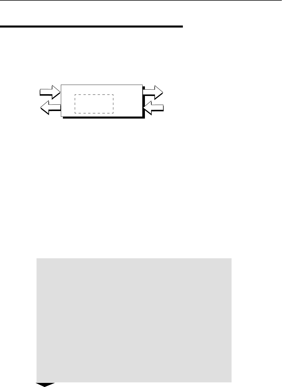
IP Filter Configuration
APR 2001 Rev 03 45
IP Filter Configuration
Two different IP filters are available: a packet filter, and an address filter. The IP packet filter determines which
type of packets are allowed to pass through a unit. If the IP Packet Filter is OFF, the unit passes all packets. If
the IP Packet Filter is ON, the unit passes only IP and ARP (Address Resolution Protocol) packets.
IP address filters are actually tables that contain lists of IP addresses. If an address is listed in the table, the
unit will pass data packets to other IP addresses. If it is not listed, the unit will not pass data packets.
When IP address filtering is enabled, all IP packet are sorted according to the following conditions:
1. If the source IP address is contained in one of the IP address lists, IP packets coming from the wire will
be forwarded to the air. If not, IP packets are dropped.
2. If the destination IP address is contained in one of the IP address lists, IP packets coming from the air
will be forwarded to the wire. If not, IP packets are dropped.
Each IP address filter is defined by a range and a base value. IP address filtering improves system security and
helps manage data throughput.
Viewing IP Filter Configuration
➧ To view current IP filter configuration
1. From the Main Menu, select IP Filter Configuration and press Enter. The IP Filter
Configuration menu is displayed.
IP Address Filter Table
xxx.xx.xx.x
xxx.xx.xx.x
xxx.xx.xx.x
WireAir
Data packets pass only
if the IP address is
listed in the IP filter table
IP
Addresses
IP Filter Configuration
IP Packet Filtering -> off
IP Address Filtering off
Filter 1 Range (0-255) 0
Filter 1 Base Address 0.0.0.0
Filter 2 Range (0-255) 0
Filter 2 Base Address 0.0.0.0
Filter 3 Range (0-255) 0
Filter 3 Base Address 0.0.0.0
Filter 4 Range (0-255) 0
Filter 4 Base Address 0.0.0.0
Filter 5 Range (0-255) 0
Filter 5 Base Address 0.0.0.0

Configuration
46 AWE 120-58 Installation & Configuration Guide
Example: To configure a unit to pass only IP data packets from the IP addresses in the list below,
you would configure the unit as follows:
IP Packet
Filtering
off (disabled) All packets are passed
on (enabled) Only IP (Internet Protocol) packets and ARP packets can pass
IP Address
Filtering
off (disabled) Packets from all IP addresses pass
on (enabled) Only packets whose IP addresses listed in at least one IP filter
pass. Up to five IP filters are available; each filter lists up to 255
IP addresses
Filter n Range n = 0–5 Defines how many contiguous IP addresses are in the filter’s list
of addresses
Filter n Base
Address
n = lowest IP
Address
Lowest numbered address on the filter’s list of IP addresses
192.168.2.10
192.168.2.11
192.168.2.12
192.168.2.13
194.120.3.51
194.120.3.52
194.120.3.254
194.120.3.255
194.120.4.0
194.120.4.1
IP Packet Filtering = on
IP Address Filtering = on
Filter 1 Range (0 - 255) = 4
Filter 1 Base Address = 192.168.2.10
Filter 2 Range (0 - 255) = 2
Filter 2 Base Address = 194.120.3.51
Filter 3 Range (0 - 255) = 4
Filter 3 Base Address = 194.120.3.254

IP Filter Configuration
APR 2001 Rev 03 47
Enabling IP Packet Filtering
IP Packet filtering should initially be set to off so you can start from a known state and observe changes that
result from using the IP packet filter.
➧ To enable IP packet filtering
1. From the IP Filter Configuration menu, select IP Packet Filtering and press Enter. The data field
highlights.
2. Scroll to on.
3. Press Enter to make the change.
4. Press Esc to exit to the Main Menu.
Enabling IP Address Filtering
➧ To enable IP address filtering
1. From the IP Filter Configuration menu, select IP Address Filtering and press Enter. The data
field highlights.
2. Scroll to on and press Enter.
3. Press Esc to exit to the Main Menu.
IP Filter Configuration
IP Packet Filtering -> off
IP Address Filtering off
Filter 1 Range (0-255) 0
Filter 1 Base Address 0.0.0.0
Filter 2 Range (0-255) 0
Filter 2 Base Address 0.0.0.0
Filter 3 Range (0-255) 0
Filter 3 Base Address 0.0.0.0
Filter 4 Range (0-255) 0
Filter 4 Base Address 0.0.0.0
Filter 5 Range (0-255) 0
Filter 5 Base Address 0.0.0.0

Configuration
48 AWE 120-58 Installation & Configuration Guide
Setting IP Address Filter Range
➧ To set IP address filter range
1. From the IP Filter Configuration menu, select Filter 1 Range (0 - 255) and press Enter. The
data field highlights.
2. Type in the number of contiguous addresses in the filter list (0 - 255) and press Enter.
3. Press Esc to exit to the Main Menu.
Setting the IP Filter Base Address
➧ To set IP filter base address
1. From the IP Filter Configuration menu, select Filter 1 Base Address and press Enter. The data
field highlights.
2. Type the IP address and press Enter. The data field highlights.
3. Press Esc to exit to the Main Menu.

RF Station Configuration
APR 2001 Rev 03 49
RF Station Configuration
The RF Station Configuration menu enables you to choose the operating mode, run some tests and optimize
the RF link. Four tests can be run from this menu: link monitor test, transmit test, receive test and RSSI test.
You can optimize a link by setting the maximum remote distance to a remote and by controlling the rate of
data throughput (throttling). You can also block a unit so that it cannot pass any data.
Viewing Current RF Station Configuration
➧ To view current RF station configuration
1. From the Main Menu, select RF Station Configuration and press Enter. The RF Station
Configuration menu is displayed.
Operating Mode Four modes are available: Normal Mode, Receive Test,
Transmit Test, and RSSI Test
RF Transmit Status Determines if data transmissions through the unit will be
blocked or passed
Link Monitor Period Period determines the amount of test data that is used to
test the link. The smaller the number, the larger the
amount of test data and test data overhead. A non-zero
value starts the link monitor test
Test Mode Timer
Minutes
Maximum time in minutes that a unit will be allowed to
stay in test mode
Maximum Remote
Distance
Distance value compensates for polling delay due to large
distances
Link Monitor Remote
Station Rank
Rank (or ID number) of the remote that you want to test
RF Station Configuration
Operating Mode -> Normal Mode
RF Transmit Status unblocked
Link Monitor Period (0=OFF, 1-10000) 0
Test Mode Timer Minutes (1-1000) 20
Base Station Only Parameters
Maximum Remote Distance 5 Km
Link Monitor Remote Station Rank 1
Remote Station Only Parameters
Throttle Enable off
Throttle Level (1-50) 1

Configuration
50 AWE 120-58 Installation & Configuration Guide
2. Press Esc to exit to the Main Menu.
Throttle Enable Turns throttling (data throughput control) on or off
Throttle Level Determines the data rate of a remote unit. When
throttling is enabled, the data rate passed is equal to the
throttling level times 128 kbps
RF Station Configuration
APR 2001 Rev 03 51
Setting the Operating Mode
Four modes are available: Normal Mode, Receive Test, Transmit Test, and RSSI Test.
➧ To set the operating mode
1. From the Main Menu, select RF Station Configuration and press Enter. The RF Station
Configuration menu is displayed.
2. Select Operating Mode and press Enter. The data field highlights.
3. Press the arrow keys to select the desired mode: Normal mode, Transmit mode, Receive mode or RSSI
mode.
4. Press Enter. The screen clears, and the Mode LED on the unit is ON. The color of the Mode LED
indicates the current mode: Normal Mode = off, Transmit Test = red, Receive Test = green and
RSSI Test = orange.
Normal Mode Normal operating mode of a unit. Unit transmits and receives data in
both directions across the RF link.
Link Monitor test is run with the unit set to Normal mode. (You can
view the link statistics with Link Monitor Display.)
Receive
Test
Receives test data only. Processes expected packet data and displays
statistics on RS-232 monitor. Use this mode to test a unit’s ability to
receive data.
Transmit
Test
Transmits test data only. Sends known packet data to the receiving unit.
Use this mode to test a unit’s abilty to transmit data.
RSSI Test RSSI (Received Signal Strength Indicator) test–indicates signal strength.
Unit receives known data packets and displays fade margin data on the
Air LED. Use this mode to get a quick visual indication of the signal
strength. See Performing the RSSI Test, page 59 for more information.
RF Station Configuration
Operating Mode -> Normal Mode
RF Transmit Status unblocked
Link Monitor Period (0=OFF, 1-10000) 0
Test Mode Timer Minutes (1-1000) 20
Base Station Only Parameters
Maximum Remote Distance 5 Km
Link Monitor Remote Station Rank 1
Remote Station Only Parameters
Throttle Enable off
Throttle Level (1-50) 1
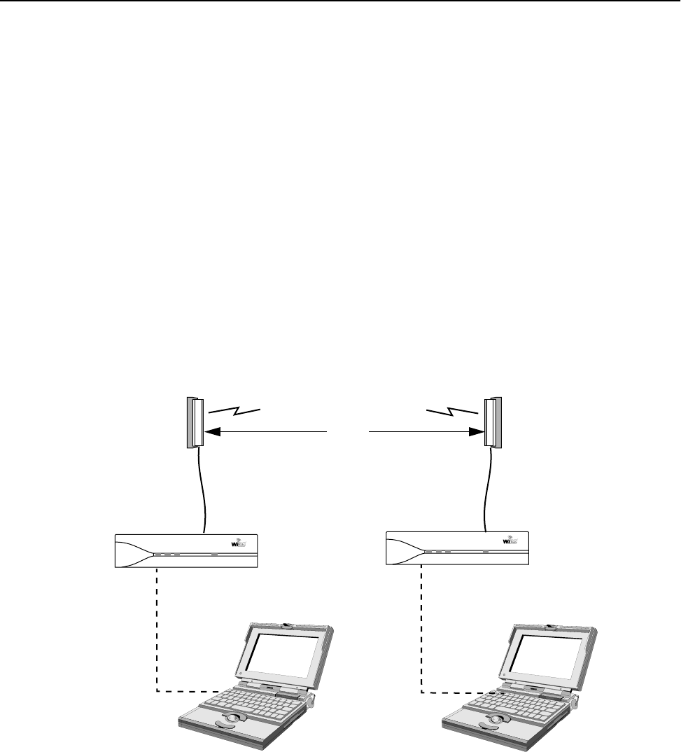
Configuration
52 AWE 120-58 Installation & Configuration Guide
5. To exit a mode, briefly disconnect the power or press and hold the Mode button on the rear panel of the
unit. The Mode LED goes off (normal mode) and the Login menu is displayed.
Note: The operating mode can also be set with the Mode button on the back of the AWE. See Setting
Operating Mode with the Mode Button, page 102 for more information.
General Equipment Setup for Performing RF Tests
The general equipment setup is shown below. The specific setup depends on the test you want to run.
• To perform the Normal Mode (Link Monitor) test you need to connect a PC to either the base
station or a remote unit.
• To perform the Transmit Test or Receive Test you need at least one base station with PC, a remote
station with PC, and an RF link between units. See Establishing a Basic RF Link, page 21 for instructions
about establishing an RF link.
• To perform the RSSI test you need a PC for the unit that will transmit. The receiving unit does not
require a PC. You can also run this test with the Mode button.
General Equipment Setup
Before you run any tests, you should set the number of test minutes, as descibed below in Setting Test Mode
Timer Minutes, page 53.
Base Unit Remote Unit
PC PC
RS-232
Serial
Cable
RS-232
Serial
Cable
COM
Port
COM
Port
Air Mode Wire Power
Air Mode Wire Power
To Serial PortTo Serial Port
2 m
minimum

RF Station Configuration
APR 2001 Rev 03 53
Setting Test Mode Timer Minutes
Before you run any of these tests, you should set the maximum time, in minutes, that a unit will be allowed to
stay in test mode. When this time period expires, the AWE unit performs an automatic software reboot and
returns to Normal mode. (Test mode timer minutes setting applies only to Transmit Test, Receive Test, and
RSSI Test modes.)
Note: The test mode timer minutes can be changed only with this menu. This time period does not apply to
Normal mode or the Link Monitor test. See Setting Operating Mode with the Mode Button, page 102.
➧ To set test mode timer minutes
1. From the Main Menu, select RF Station Configuration and press Enter. The RF Station
Configuration menu is displayed.
2. Select Test Mode Timer Minutes and press Enter. The data field highlights.
3. Type the desired time in minutes (1-1000). (20 minutes is a suggested starting value.)
4. Press Enter.
5. Press Esc to exit to the Main Menu.
RF Station Configuration
Operating Mode Normal Mode
RF Transmit Status unblocked
Link Monitor Period (0=OFF, 1-10000) 0
Test Mode Timer Minutes (1-1000) -> 20
Base Station Only Parameters
Maximum Remote Distance 5 Km
Link Monitor Remote Station Rank 1
Remote Station Only Parameters
Throttle Enable off
Throttle Level (1-50) 1

Configuration
54 AWE 120-58 Installation & Configuration Guide
Performing Link Monitor Test (Normal Mode)
The link monitor test can be run from either a base station or a remote unit that is set to Normal Mode. The
test operates in parallel with the message stream, so it consumes some of the link’s total data capacity. You
can control the ratio of test data to message data (and thereby control the amount of test data overhead) by
setting the link monitor period. See Setting the Link Monitor Period, page 61 for more information.
Note: Link monitor test stays in effect even if you power cycle or reboot units, so you must turn it off using
the Link Monitor Period (0 = OFF) setting.
➧ To perform Link Monitor test from a base station
1. Connect the test PC to the Serial port of the base station. See General Equipment Setup for Performing RF
Tests, page 52.
2. Log in to the unit and go to the Main Menu.
3. Select RF Station Configuration and press Enter. The RF Station Configuration menu is
displayed.
4. Select Operating Mode and press Enter. The data field highlights.
5. Press the arrow keys to select Normal mode and press Enter.
6. Select RF Transmit Status and press Enter. The data field highlights.
7. Press the arrow keys to select unblocked and press Enter.
8. Select Link Monitor Remote Station Rank and press Enter. The data field highlights.
9. Type the rank of the remote unit that you want to link to and press Enter. (The rank is the identification
number of the remote unit. The rank of a remote can be any number from 1 – 1000. See Setting the
Station Rank, page 69.)
10. Select Link Monitor Period and press Enter. The data field highlights.
11. Type a link monitor period (1) and press Enter. Link Monitor starts as soon as a non-zero value is
entered in the field. (A setting of 1 means that 50% of all data is test data.)
RF Station Configuration
Operating Mode -> Normal Mode
RF Transmit Status unblocked
Link Monitor Period (0=OFF, 1-10000) 0
Test Mode Timer Minutes (1-1000) 20
Base Station Only Parameters
Maximum Remote Distance 5 Km
Link Monitor Remote Station Rank 1
Remote Station Only Parameters
Throttle Enable off
Throttle Level (1-50) 1

RF Station Configuration
APR 2001 Rev 03 55
12. View the link statistics. From the Main Menu select Link Monitor Display and press Enter. The RF
Link Monitor Statistics window is displayed.
13. Check for BER = 0.0E+00 and Corr Power between 15 – 50 dB. If the Corr Power is <15 dB the
receive signal is probably too weak. If the power is >55 dB the receiving unit is probably saturated. See
Viewing Link Monitor Statistics, page 101 for more information about Link Monitor Statistics.
If you have problems, ensure that the unit is configured to its basic default settings (see Restoring Factory
Configurations, page 99) and reconfigure the unit, or contact Wi-LAN Technical Assistance Center.
14. When finished viewing link monitor statistics, disable Link Monitor to remove the test overhead data
from the RF link. Select RF Station Configuration from the Main Menu and press Enter. The RF
Station Configuration menu is displayed.
15. Select Link Monitor Period and press Enter. The field is highlighted.
16. Type 0 in the field and press Enter. The link monitor test ends.
17. Press Esc to exit.
➧ To perform Link Monitor test from a remote unit
1. Connect the test PC to the Serial port of the remote unit. See General Equipment Setup for Performing RF
Tests, page 52.
2. Log in to the unit and go to the Main Menu.
RF Link Monitor Statistics
Link Monitor Rank 1
Base to Remote BER 0.0E+00
Remote to Base BER 0.0E+00
Missed Packet Count 0
Base to Remote Env Power 27
Base to Remote Corr Power 28
Remote to Base Env Power 29
Remote to Base Corr Power 30

Configuration
56 AWE 120-58 Installation & Configuration Guide
3. Select RF Station Configuration and press Enter. The RF Station Configuration menu is
displayed.
4. Select Operating Mode and press Enter. The data field highlights.
5. Press the arrow keys to select Normal mode and press Enter.
6. Select RF Transmit Status and press Enter. The data field highlights.
7. Press the arrow keys to select unblocked and press Enter.
8. Select Link Monitor Remote Station Rank and press Enter. The data field highlights and the
remote automatically connects with the base station.
9. Select Link Monitor Period and press Enter. The data field highlights.
10. Type a link monitor period (1) and press Enter. Link Monitor starts as soon as a non-zero value is
entered in the field. (A setting of 1 means that 50% of all data is test data.)
11. View the link statistics. From the Main Menu select Link Monitor Display and press Enter. The RF
Link Monitor Statistics window is displayed.
12. Check for BER = 0.0E+00 and Corr Power between 15 – 50 dB. If the Corr Power is <15 dB the
receive signal is probably too weak. If the power is >55 dB the receiving unit is probably saturated. See
Viewing Link Monitor Statistics, page 101 for more information about Link Monitor Statistics.
RF Station Configuration
Operating Mode -> Normal Mode
RF Transmit Status unblocked
Link Monitor Period (0=OFF, 1-10000) 0
Test Mode Timer Minutes (1-1000) 20
Base Station Only Parameters
Maximum Remote Distance 5 Km
Link Monitor Remote Station Rank 1
Remote Station Only Parameters
Throttle Enable off
Throttle Level (1-50) 1
RF Link Monitor Statistics
Link Monitor Rank 1
Base to Remote BER 0.0E+00
Remote to Base BER 0.0E+00
Missed Packet Count 0
Base to Remote Env Power 27
Base to Remote Corr Power 28
Remote to Base Env Power 29
Remote to Base Corr Power 30

RF Station Configuration
APR 2001 Rev 03 57
If you have problems, ensure that the unit is configured to its basic default settings (see Restoring Factory
Configurations, page 99) and reconfigure the unit or contact Wi-LAN customer support.
13. When you finish viewing link monitor statistics, disable Link Monitor to remove the test overhead data
from the RF link. Select RF Station Configuration from the Main Menu and press Enter. The RF
Station Configuration menu is displayed.
14. Select Link Monitor Period and press Enter. The field is highlighted.
15. Type 0 in the field and press Enter. The link monitor test ends.
16. Press Esc to exit.
Note: When testing, it is possible to run the link monitor in both directions over one link by enabling link
monitor on the base and the remote at the same time. This situation should be avoided during normal
operation because it causes needless overhead.
Performing Transmit and Receive Tests
When performing transmit or receive tests, one unit is set up to operate in Transmit Test mode and the other
unit is set up to operate in Receive Test mode. The transmitting unit sends packets of known data to the
receiving unit. The receiving unit analyzes the data and displays link statistics on the PC connected to the
Serial port.
➧ To set up the transmit unit
1. Connect a PC to the Serial port of the unit.
2. Log in to the unit and go to the Main Menu.
3. From the Main Menu, select RF Station Configuration and press Enter. The RF Station
Configuration menu is displayed.
4. Select Operating Mode and press Enter. The field highlights.
5. Select Transmit Test and press Enter. The Mode LED on the unit is red, indicating that the unit is
transmitting.
➧ To set up the receive unit
1. Connect a PC to the Serial port of the unit.
2. Log in to the unit and go to the Main Menu.
3. From the Main Menu, select RF Station Configuration and press Enter. The RF Station
Configuration menu is displayed.
4. Select Operating Mode and press Enter. The field highlights.
5. Select Receive Test and press Enter. The Mode LED on the turns green, indicating that the unit is
receiving. The link statistics are displayed on the receiving unit. Alternating lines of statistics across the
screen indicate that data is incoming. See the following example.
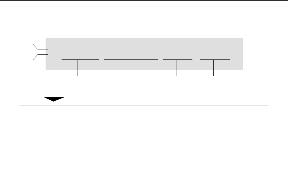
Configuration
58 AWE 120-58 Installation & Configuration Guide
Link Statistics Example
6. Check for BER = 0.0E+00 and CorrP between 15 – 50 dB. If the CorrP is <15 dB the receive signal is
probably too weak. If the power is >55 dB the receiving unit is probably saturated.
If you have problems ensure that the unit is configured to its basic default settings (see Restoring Factory
Configurations, page 99) and reconfigure the unit, or contact Wi-LAN customer support.
7. To end the test, briefly disconnect power from the unit or press and hold the Mode button to return to
Normal mode.
BER Bit Error Rate
MPC Missed Packet Count
EnvP Envelope Power—the power of the received signal inlcuding noise,
measured in dB (0–63)
CorrP Correlation Power—the power of the received signal, excluding noise,
measured in dB (0–63)
- BER = 0.0E+00, MPC = 0, EnvP = 63, CorrP = 63
| BER = 0.0E+00, MPC = 0, EnvP = 63, CorrP = 63
Bit Error Rate Missed
Packet
Count
Envelope Power Correlation Power
Previous
Sample
Current
Sample

RF Station Configuration
APR 2001 Rev 03 59
Performing the RSSI Test
RSSI mode is used to measure the signal strength (fade margin) of a system. When running the test between
two units, the transmit unit is set to Transmit Test mode (using either the RF Station Configuration menu or
the Mode button). The receive unit is put into RSSI Test mode (using either the RF Station Configuration
menu or the Mode button). The Air LED on the receiving unit indicates the fade margin.
➧ To run the RSSI test
1. Put the receiving unit into RSSI mode. See Setting the Operating Mode, page 51 or Setting Operating Mode
with the Mode Button, page 102. The Mode LED is orange when the unit is in RSSI mode.
2. Put the transmiting unit into Transmit Test mode. The Mode LED on the unit is red, indicating that
the unit is in transmit mode. See Setting the Operating Mode, page 51 or Setting Operating Mode with the
Mode Button, page 102.
3. Observe the color of the Air LED on the receiving unit. The Air LED is green when the signal strength is
acceptable.
4. To exit from the test, briefly disconnect power from the unit or press and hold the Mode button to
return to Normal mode.
Air LED Color Signal Strength
Green Reliable signal—greater than 15 dB fade margin
Orange Marginal signal—between 11 and 15 dB fade margin
Red Poor signal—less than 10 dB fade margin
Blank No signal at all
Configuration
60 AWE 120-58 Installation & Configuration Guide
Setting the RF Transmit Status
This setting can block a unit (or link) from carrying data traffic. It is used to disable units and to discontinue
service to customers, if necessary.
➧ To set RF transmit status
1. From the Main Menu, select RF Station Configuration and press Enter. The RF Station
Configuration menu is displayed.
2. Select RF Transmit Status and press Enter. The data field highlights.
3. Select a setting.
4. Press Enter.
5. Press Esc to exit to the Main Menu.
unblocked Unit passes data in both directions (default setting)
blocked Does not pass data in either direction
RF Station Configuration
Operating Mode Normal Mode
RF Transmit Status -> unblocked
Link Monitor Period (0=OFF, 1-10000) 0
Test Mode Timer Minutes (1-1000) 20
Base Station Only Parameters
Maximum Remote Distance 5 Km
Link Monitor Remote Station Rank 1
Remote Station Only Parameters
Throttle Enable off
Throttle Level (1-50) 1
RF Station Configuration
APR 2001 Rev 03 61
Setting the Link Monitor Period
The Link Monitor Period determines the ratio of test data to message data that is sent when you run the link
monitor test. The higher the period number, the smaller the ratio of test data to message data. The following
diagram shows the ratios of test data to link data
Link Monitor Period Settings
See Performing Link Monitor Test (Normal Mode), page 54 for information about running the Link Monitor test.
➧ To set Link Monitor Period
1. From the Main Menu, select RF Station Configuration and press Enter. The RF Station
Configuration menu is displayed.
2. Select Link Monitor Period and press Enter. The data field highlights.
3. Type the period setting (0=OFF, 1-10000)
4. Press Enter. The test starts as soon as a non-zero value is entered.
5. Press Esc to exit to the Main Menu.
Period Setting
Test Msg
1
2
3
Test Msg Msg
Test Msg Msg Msg
50% (1/2)
33.3% (1/3)
25% (1/4)
Packet Ratio
(Test/Link)
Test = test data
Msg = message data
RF Station Configuration
Operating Mode Normal Mode
RF Transmit Status unblocked
Link Monitor Period (0=OFF, 1-10000) -> 1
Test Mode Timer Minutes (1-1000) 20
Base Station Only Parameters
Maximum Remote Distance 5 Km
Link Monitor Remote Station Rank 1
Remote Station Only Parameters
Throttle Enable off
Throttle Level (1-50) 1

Configuration
62 AWE 120-58 Installation & Configuration Guide
Setting Maximum Remote Distance (Base Station Only)
The Maximum Remote Distance setting is used to optimize dynamic polling by compensating for time delays
caused by long distances between the sending unit and the receiving unit.
➧ To set the maximum remote distance
1. From the Main Menu, select RF Station Configuration and press Enter. The RF Station
Configuration menu is displayed.
2. Select Maximum Remote Distance and press Enter. The data field highlights.
3. Press the arrow keys to set the distance of the furthest remote unit (5 km increments are used).
4. Press Enter.
5. Press Esc to exit to the Main Menu.
IMPORTANT
In the base unit, the Maximum Remote Distance should always be set to the distance
between the base and the farthest remote.
RF Station Configuration
Operating Mode Normal Mode
RF Transmit Status unblocked
Link Monitor Period (0=OFF, 1-10000) 0
Test Mode Timer (1-1000)mins 20
Base Station Only Parameters
Maximum Remote Distance -> 5 Km
Link Monitor Remote Station Rank 1
Remote Station Only Parameters
Throttle Enable off
Throttle Level (1-50) 1

RF Station Configuration
APR 2001 Rev 03 63
Setting Link Monitor Remote Station Rank
When you run the Link Monitor Test from a base station, you need to specify the rank (ID number) of the
remote that you want to test. When you run the link monitor test from a remote, there is only one base, so
the rank number does not need to be entered.
➧ To set the link monitor remote station rank
1. From the Main Menu, select RF Station Configuration and press Enter. The RF Station
Configuration menu is displayed.
2. Select Link Monitor Remote Station Rank and press Enter. The data field highlights.
3. Type the station rank (ID#) of the remote to test.
4. Press Enter.
5. Press Esc to exit to the Main Menu.
RF Station Configuration
Operating Mode Normal Mode
RF Transmit Status unblocked
Link Monitor Period (0-OFF, 1-10000) 0
Test Mode Timer Minutes (1-1000) 20
Base Station Only Parameters
Maximum Remote Distance 5 Km
Link Monitor Remote Station Rank -> 1
Remote Station Only Parameters
Throttle Enable off
Throttle Level (1-50) 1

Configuration
64 AWE 120-58 Installation & Configuration Guide
Adjusting Throttling (Remote Station Only)
Throttling enables you to control the rate that data passes though a remote, so data throughput can be
adjusted to make the data rate compatible with the rest of the system. Throttling restricts the flow of data
from air to wire or from wire to air. When throttling is enabled, the amount of data passed is equal to the
throttling level times 128 kbps, to a maximum of 6.4 Mbps. Throttling applies to both down link and up link
traffic, so a throttle level of 1 means the unit will pass 128 kbps in each direction. A throttle level of 50 means
that 50 x 128 kbps will be passed. When throttling is disabled, the unit uses the maximum available bandwidth.
The default setting is to disable throttling.
➧ To enable throttling
1. From the Main Menu, select RF Station Configuration and press Enter. The RF Station
Configuration menu is displayed.
2. Select Throttle Enable and press Enter. The data field highlights.
3. Scroll to select on or off, and press Enter.
4. Press Esc to exit to the Main Menu.
➧ To set the throttle level
1. Set Throttle Enable to on, then select Throttle Level from the RF Conguration menu and press
Enter. The data field highlights.
2. Type a value from 1–50 to select the data throughput rate (where 1 = 1 x 128 kbps, 50 = 50 x 128 kbps)
and press Enter.
3. Press Esc to exit to the Main Menu.
RF Station Configuration
Operating Mode Normal Mode
RF Transmit Status unblocked
Link Monitor Period (0=OFF, 1-10000) 0
Test Mode Timer (1-1000)mins 20
Base Station Only Parameters
Maximum Remote Distance 5 Km
Link Monitor Remote Station Rank 1
Remote Station Only Parameters
Throttle Enable -> off
Throttle Level (1-50) 1

Radio Module Configuration
APR 2001 Rev 03 65
Radio Module Configuration
The Radio Module Configuration menu is used to change several key parameters, including station type,
station rank, and security passwords. Because these settings can affect service, they are changed in three
progessive stages: new, current, and flash. (New and current are for temporary storage, while flash is for
long-term storage.) The general procedure for changing settings with the Radio Module Configuration menu
follows.
1. View the current Radio Module Configuration menu. See Viewing the Radio Module Configuration, page 65.
2. Select Config Test Minutes. To begin, enter a time of 15–20 minutes. See Setting Config Test
Minutes, page 67.
3. Select a parameter and, if necessary, change the value in the "New" column.
4. After making changes, select Reboot New RF Configuration and press Enter. The unit reboots
and the "New" settings become the "Current" settings of the unit. See Rebooting and Saving RF Module
Configurations, page 84.
5. If the unit operates as expected, you can save the current settings to "Flash". See Rebooting and Saving
RF Module Configurations, page 84.
If current settings do not operate as expected, do not save them to "Flash". Either change the current
settings or wait for the Config Test Minutes time period to expire. At expiry, the unit will
automatically reboot and revert to the last-saved flash memory settings. See Rebooting and Saving RF
Module Configurations, page 84.
Viewing the Radio Module Configuration
➧ To view the current radio module configuration
1. From the Main Menu, select Radio Module Configuration and press Enter. The Radio Module
Configuration menu is displayed.
Radio Module Configuration
New Current Flash
Station Type -> Remote Unit Remote Unit Remote Unit
Station Rank (1-1000) 1 1 1
Center Frequency (57410-58338) 5.7874 GHz 5.7874 GHz 5.7874 GHz
Security Password 1 (Hex) 1 1 1
Security Password 2 (Hex) 10 10 10
Security Password 3 (Hex) 100 100 100
Security Password 4 (Hex) 1000 1000 1000
Security Password 5 (Hex) 10000 10000 10000
Scrambling Code (Hex) 0 0 0
Acquisition Code (0-15) 1 1 1
Config Test Minutes (1-120) 30 30 30
Tx Power Level Adjust 0 dB 0 dB 0 dB
Base Station Only Parameters
Repeater Mode off off off
System Symmetry Type Asymmetric Asymmetric Asymmetric
Dynamic Polling Level (1-100) 1 1 1
Remote Station Only Parameters
Remote Unit RF Group (0-63) 0 0 0
Reboot New RF configuration Press Enter to Execute
Save Current Config to Flash Press Enter to Execute

Configuration
66 AWE 120-58 Installation & Configuration Guide
2. Press Esc to exit to the Main Menu.
Station Type Defines unit as either a base station or a remote station
Station Rank For a base station, the number of remotes that the base polls
For a remote, the polling ID # of the remote
Center Frequency Defines the channel the unit uses to transmit and receive
Security Password nPassword(s) for the unit
Scrambling Code Code used to scramble messages
Acquisition Code Code used to reduce system-induced interferance in a multi-
sector system
Config Test Minutes Amount of time before unit returns to its pre-configuration state
Tx Power Level Adjust Reduces the power below maximum Tx power by the specified
amount in dB.
Repeater Mode Sets up a base station to pass data to and from remotes rather
than function as a control unit
System Symmetry Type Defines the amount of priority the base unit has when polling the
remotes
Dynamic Polling Level Number of polling cycles that inactive remote units are ignored by
the base station
Remote Unit RF Group Identifies the goup number of the remote unit
Remote units with same RF group number can communicate
directly with each other
Reboot new RF
configuration
Reboots unit to save New settings as Current settings
Save Current Config
to Flash
Stores current settings in flash memory

Radio Module Configuration
APR 2001 Rev 03 67
Setting Config Test Minutes
When changing Radio Module Configuration settings, you may enter settings that cause a unit or system to
not function as expected. If this happens, you can return to the last-saved settings if you first set the Config Test
Minutes test period. When this test period expires, the unit automatically reboots and returns to its last-saved
flash memory settings. The time period can be fixed from 1 to 120 minutes.
Tip: To begin, enter a time period of 30 minutes. If the time period is too short, you will not have enough
time to make configuration changes and save them to flash ROM. If the time period is long, you will have to
wait a long time before the unit automatically reboots and restores the settings to the original flash ROM
state.
➧ To set the config test timeout period
1. From the Main Menu, select Radio Module Configuration and press Enter. The Radio Module
Configuration menu is displayed.
2. Select Config Test Minutes and press Enter. The data field highlights.
3. Type the number of minutes (1-120) and press Enter. The number of minutes is stored in the New state.
4. Select Reboot New RF Configuration and press Enter. The unit reboots and the AWE 120-58
Login menu is displayed. The unit will now use the current settings to operate, for the length of time
specified by Config Test Minutes.
5. To save the current setting(s) to flash memory, log in, go to the Main Menu, and select Radio Module
Configuration, Save Current Config to Flash. See Rebooting and Saving RF Module
Configurations, page 84.
6. Press Esc to exit to the Main Menu.
Radio Module Configuration
New Current Flash
Station Type Remote Unit Remote Unit Remote Unit
Station Rank (1-1000) 1 1 1
Center Frequency (57410-58338) 5.7874 GHz 5.7874 GHz 5.7874 GHz
Security Password 1 (Hex) 1 1 1
Security Password 2 (Hex) 10 10 10
Security Password 3 (Hex) 100 100 100
Security Password 4 (Hex) 1000 1000 1000
Security Password 5 (Hex) 10000 10000 10000
Scrambling Code (Hex) 0 0 0
Acquisition Code (0-15) 0 0 0
Config Test Minutes (1-120) -> 30 30 30
Tx Power Level Adjust 0 dB 0 dB 0 dB
Base Station Only Parameters
Repeater Mode off off off
System Symmetry Type Asymmetric Asymmetric Asymmetric
Dynamic Polling Level (1-100) 1 1 1
Remote Station Only Parameters
Remote Unit RF Group (0-63) 0 0 0
Reboot New RF configuration Press Enter to Execute
Save Current Config to Flash Press Enter to Execute

Configuration
68 AWE 120-58 Installation & Configuration Guide
Setting the Station Type
Each unit must be set up as either a base station or a remote station. In a given system there is only one base
station, but there can be numerous remote stations. (A base station can also be set up as a repeater base.)
You define the unit as a base station or remote unit by setting the Station Type.
➧ To set the station type
1. From the Main Menu, select Radio Module Configuration and press Enter. The Radio Module
Configuration menu is displayed.
2. Select Station Type and press Enter. The data field highlights.
3. Scroll to select the Station Type (base station or remote unit).
4. Press Enter. The new setting is displayed in the "New" column.
5. Select Reboot New RF Configuration and press Enter. The unit reboots and the AWE 120-58
Login menu is displayed. The unit now runs using the "Current" station type for the amount of time
specified by Config Test Minutes.
6. To save the current setting(s) to flash memory, log in, go to the Main Menu, and select Radio Module
Configuration, Save Current Config to Flash. See Rebooting and Saving RF Module
Configurations, page 84.
7. Press Esc to exit to the Main Menu.
Radio Module Configuration
New Current Flash
Station Type -> Remote Unit Remote Unit Remote Unit
Station Rank (1-1000) 1 1 1
Center Frequency (57410-58338) 5.7874 GHz 5.7874 GHz 5.7874 GHz
Security Password 1 (Hex) 1 1 1
Security Password 2 (Hex) 10 10 10
Security Password 3 (Hex) 100 100 100
Security Password 4 (Hex) 1000 1000 1000
Security Password 5 (Hex) 10000 10000 10000
Scrambling Code (Hex) 0 0 0
Acquisition Code (0-15) 1 1 1
Config Test Minutes (1-120) 30 30 30
Tx Power Level Adjust 0 dB 0 dB 0 dB
Base Station Only Parameters
Repeater Mode off off off
System Symmetry Type Asymmetric Asymmetric Asymmetric
Dynamic Polling Level (1-100) 1 1 1
Remote Station Only Parameters
Remote Unit RF Group (0-63) 0 0 0
Reboot New RF configuration Press Enter to Execute
Save Current Config to Flash Press Enter to Execute

Radio Module Configuration
APR 2001 Rev 03 69
Setting the Station Rank
Station Rank is defined two different ways, which depend on the station type: For a base station, rank is the
total number of remotes that a base will poll. For a remote unit, rank is a unique polling ID number that identifies
a remote to a base station.
When it polls remotes, the base station begins polling at the remote with rank number 1, then proceeds to
the remote with rank number 2, then goes to the remote with rank number 3, and so on. The base continues
polling remotes until it reaches the remote with the highest rank number. The base then repeats the polling
cycle.
Note: Dynamic polling gives you some control over the polling process. See Setting Dynamic Polling Level (Base
Station Only), page 80.
➧ To set the station rank
1. From the Main Menu, select Radio Module Configuration and press Enter. The Radio Module
Configuration menu is displayed.
2. Select Station Rank (1-1000).
3. Type the rank (a number from 1–1000) of the station.
4. Press Enter. The new setting is displayed in the "New" column.
5. Select Reboot New RF Configuration and press Enter. The unit reboots and the AWE 120-58
Login menu is displayed. The unit now runs using the "Current" rank for the amount of time specified
by Config Test Minutes.
6. To save the current setting(s) to flash memory, log in, go to the Main Menu, and select Radio Module
Configuration, Save Current Config to Flash. See Rebooting and Saving RF Module
Configurations, page 84.
7. Press Esc to exit to the Main Menu.
Radio Module Configuration
New Current Flash
Station Type Remote Unit Remote Unit Remote Unit
Station Rank (1-1000) -> 1 1 1
Center Frequency (57410-58338) 5.7874 GHz 5.7874 GHz 5.7874 GHz
Security Password 1 (Hex) 1 1 1
Security Password 2 (Hex) 10 10 10
Security Password 3 (Hex) 100 100 100
Security Password 4 (Hex) 1000 1000 1000
Security Password 5 (Hex) 10000 10000 10000
Scrambling Code (Hex) 0 0 0
Acquisition Code (0-15) 1 1 1
Config Test Minutes (1-120) 30 30 30
Tx Power Level Adjust 0 dB 0 dB 0 dB
Base Station Only Parameters
Repeater Mode off off off
System Symmetry Type Asymmetric Asymmetric Asymmetric
Dynamic Polling Level (1-100) 1 1 1
Remote Station Only Parameters
Remote Unit RF Group (0-63) 0 0 0
Reboot New RF configuration Press Enter to Execute
Save Current Config to Flash Press Enter to Execute
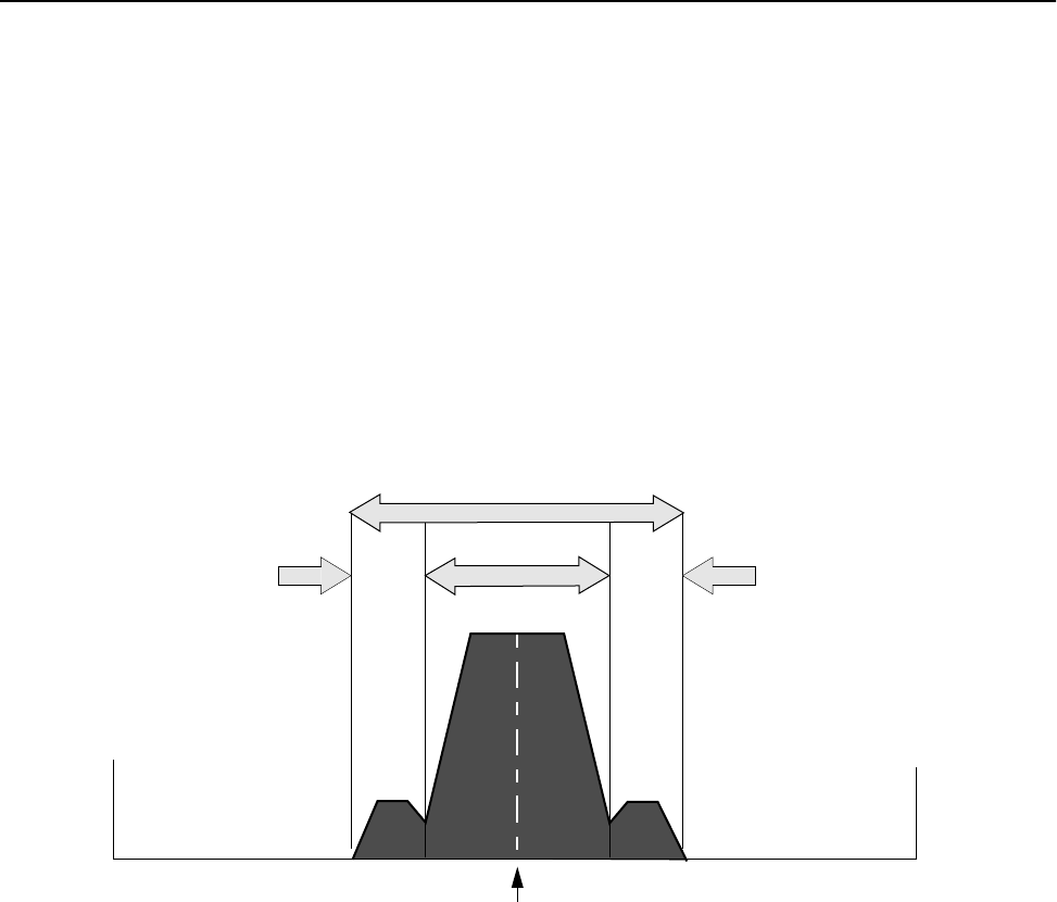
Configuration
70 AWE 120-58 Installation & Configuration Guide
Setting the Center Frequency
A center frequency defines the RF channel that a unit uses to transmit and receive. The AWE 120-58 can
operate at a center frequency ranging from 5.7410 GHz to 5.8338 GHz, in 400 kHz steps. All units in the
same system must be set to the same center frequency.
If you plan to co-locate AWE 120-58 systems, you will need to use more than one center frequency.You will
choose center frequencies that are well-separated from each other. The following section Choosing Center
Frequencies explains how to choose center frequencies.
Choosing Center Frequencies
A simplified diagram of the spectrum around a center frequency (when transmitting) is shown below.
Only the 33 MHz data region of the 66 MHz spectrum contains data; the remaining 16 MHz side lobes
contain no useful information (frequency ranges given are approximate).The side lobes operate at a much
lower power than the data region.
If only one center frequency is required, simply choose a frequency between 5.7410 GHz and 5.8338 GHz (in
400 kHz increments). You will probably choose a center frequency where the 5.8 GHz ISM band is cleanest,
meaning a frequency where no other people are transmitting.
If two or more AWE 120-58 systems must be co-located, center frequencies are selected that have as much
separation as possible so different systems do not interfere with each other. It is very important that the 33
MHz data regions of adjacent systems do not overlap. System performance is also better if the side lobes of
one system do not overlap the data region of another system. It does not matter if the side-lobes of two
systems overlap.
16 MHz16 MHz 33 MHz
Center Frequency
66 MHz
Data
SideSide
Center Frequency Spectrum
LobeLobe
Region
5.7410 GHz 5.8338 GHz
Radio Module Configuration
APR 2001 Rev 03 71
Some examples of center frequency separation and performance ratings are provided below.
These examples show that there is no benefit to separating the center frequencies of adjacent systems by
more than 66 MHz. 48 MHz of center frequency separation is more than adequate in most cases. Separation
of 33MHz is adequate for strong RF links, but weak signals will be degraded by the overlap of the side-lobes
into the data region. Overlapping of data regions is not recommended and will cause problems.
The following diagram shows seven different center frequencies in the 5.8 GHz ISM band that are spaced as
far apart as possible. If you wish, you can choose your center frequencies from these sample schemes.
Three co-located system could use the A,D and G center frequencies. Frequencies B, D and F would
probably work equally as well. Four co-located systems could use the A, C, E and G frequencies. Having
more than four co-located systems would require careful radio network planning to ensure the proper
operation of each system.
Excellent Good
Fair Poor
5.7250
5.7410
5.7562
5.7718
5.7874
5.7803
5.8182
5.8338
5.8500
Center Frequency (GHz)
3 Systems
4 Systems
ABCDEFG
Sample Center Frequency Schemes for Co-located Systems
2 Systems
1 System
Choose any two center frequencies
Choose any one center frequency

Configuration
72 AWE 120-58 Installation & Configuration Guide
➧ To set the center frequency
1. From the Main Menu, select Radio Module Configuration and press Enter. The Radio Module
Configuration menu is displayed.
2. Select Center Frequency and press Enter. The data field highlights.
3. Type the value of the RF center frequency. The value can range from 57410 GHz to 53338 GHz in steps
of 400 kHz. (Numbers are automatically rounded down to the nearest step.) All units in a system must
have the same center frequency.
4. Press Enter. The new setting is displayed in the "New" column.
5. Select Reboot New RF Configuration and press Enter. The unit reboots and the AWE 120-58
Login menu is displayed. The unit now runs using the "Current" center frequency for the amount of
time specified by Config Test Minutes.
6. To save the current setting(s) to flash memory, log in, go to the Main Menu, and select Radio Module
Configuration, Save Current Config to Flash. See Rebooting and Saving RF Module
Configurations, page 84.
7. Press Esc to exit to the Main Menu.
Radio Module Configuration
New Current Flash
Station Type Remote Unit Remote Unit Remote Unit
Station Rank (1-1000) 1 1 1
Center Frequency (57410-58338) -> 5.7874 GHz 5.7874 GHz 5.7874 GHz
Security Password 1 (Hex) 1 1 1
Security Password 2 (Hex) 10 10 10
Security Password 3 (Hex) 100 100 100
Security Password 4 (Hex) 1000 1000 1000
Security Password 5 (Hex) 10000 10000 10000
Scrambling Code (Hex) 0 0 0
Acquisition Code (0-15) 1 1 1
Config Test Minutes (1-120) 30 30 30
Tx Power Level Adjust 0 dB 0 dB 0 dB
Base Station Only Parameters
Repeater Mode off off off
System Symmetry Type Asymmetric Asymmetric Asymmetric
Dynamic Polling Level (1-100) 1 1 1
Remote Station Only Parameters
Remote Unit RF Group (0-63) 0 0 0
Reboot New RF configuration Press Enter to Execute
Save Current Config to Flash Press Enter to Execute

Radio Module Configuration
APR 2001 Rev 03 73
Setting Security Passwords
Passwords are always exchanged between units when they communicate with each other. A set of five
security passwords is assigned to each unit. The set of passwords must be exactly the same for all units in a
system. (A convenient, but non-secure option is to set all passwords to "0".) The more password levels you
use, the greater the security of your system. For example, using a set of five different passwords will result in
a highly secure system. All units in the same network must use the same set of security passwords.
➧ To set security passwords
1. From the Main Menu, select Radio Module Configuration and press Enter. The Radio Module
Configuration menu is displayed.
2. Select Security Password 1 and press Enter. The data field highlights.
3. Enter a password in Hex code and press Enter. The password is stored in the New state.
4. Select Security Password 2 and press Enter. The data field highlights.
5. Enter a different password in Hex code and press Enter. The password is stored in the New state.
6. Repeat this process until you complete all five password levels.
7. Select Reboot New RF Configuration and press Enter. The unit reboots and the AWE 120-58
Login menu is displayed. The unit now runs using the "Current" set of passwords for the amount of
time specified by Config Test Minutes.
8. To save the current setting(s) to flash memory, log in, go to the Main Menu, and select Radio Module
Configuration, Save Current Config to Flash. See Rebooting and Saving RF Module
Configurations, page 84.
9. Press Esc to exit to the Main Menu.
Radio Module Configuration
New Current Flash
Station Type Remote Unit Remote Unit Remote Unit
Station Rank (1-1000) 1 1 1
Center Frequency (57410-58338) 5.7874 GHz 5.7874 GHz 5.7874 GHz
Security Password 1 (Hex) -> 1 1 1
Security Password 2 (Hex) 10 10 10
Security Password 3 (Hex) 100 100 100
Security Password 4 (Hex) 1000 1000 1000
Security Password 5 (Hex) 10000 10000 10000
Scrambling Code (Hex) 0 0 0
Acquisition Code (0-15) 1 1 1
Config Test Minutes (1-120) 30 30 30
Tx Power Level Adjust 0 dB 0 dB 0 dB
Base Station Only Parameters
Repeater Mode off off off
System Symmetry Type Asymmetric Asymmetric Asymmetric
Dynamic Polling Level (1-100) 1 1 1
Remote Station Only Parameters
Remote Unit RF Group (0-63) 0 0 0
Reboot New RF configuration Press Enter to Execute
Save Current Config to Flash Press Enter to Execute

Configuration
74 AWE 120-58 Installation & Configuration Guide
Setting the Scrambling Code
To protect the privacy of a wireless link, units can scramble messages—the message content is rearranged so
that messages are difficult to read by unintended receivers. The scrambling code determines how messages
are scrambled by a unit. Only units with the same scrambling code as the originating unit can de-scramble and
read the message. The scrambling code can be 0-32 bits long. All units in the same wireless network must
have this setting set to the same value.
➧ To set scrambling codes
1. From the Main Menu, select Radio Module Configuration and press Enter. The Radio Module
Configuration menu is displayed.
2. Select Scrambling Code and press Enter. The data field highlights.
3. Type the code (hexidecimal number).
4. Press Enter. The new setting is displayed in the "New" column.
5. Select Reboot New RF Configuration and press Enter. The unit reboots and the AWE 120-58
Login menu is displayed. The unit now runs using the "Current" scrambling code for the amount of time
specified by Config Test Minutes.
6. To save the current setting(s) to flash memory, log in, go to the Main Menu, and select Radio Module
Configuration, Save Current Config to Flash. See Rebooting and Saving RF Module
Configurations, page 84.
7. Press Esc to exit to the Main Menu.
Radio Module Configuration
New Current Flash
Station Type Remote Unit Remote Unit Remote Unit
Station Rank (1-1000) 1 1 1
Center Frequency (57410-58338) 5.7874 GHz 5.7874 GHz 5.7874 GHz
Security Password 1 (Hex) 1 1 1
Security Password 2 (Hex) 10 10 10
Security Password 3 (Hex) 100 100 100
Security Password 4 (Hex) 1000 1000 1000
Security Password 5 (Hex) 10000 10000 10000
Scrambling Code (Hex) -> 0 0 0
Acquisition Code (0-15) 1 1 1
Config Test Minutes (1-120) 30 30 30
Tx Power Level Adjust 0 dB 0 dB 0 dB
Base Station Only Parameters
Repeater Mode off off off
System Symmetry Type Asymmetric Asymmetric Asymmetric
Dynamic Polling Level (1-100) 1 1 1
Remote Station Only Parameters
Remote Unit RF Group (0-63) 0 0 0
Reboot New RF configuration Press Enter to Execute
Save Current Config to Flash Press Enter to Execute

Radio Module Configuration
APR 2001 Rev 03 75
Setting the Acquisition Code
An acquisition code is a unique code contained within the preamble of a transmitted message. Units search
the air for messages that begin with a particular acquisition code. Messages without the correct code are
treated as interference and are rejected by a unit. Messages with the correct code are accepted and
processed. Acquisition codes serve to isolate units from each other, especially when several units operate in
close proximity or at the same frequency in a multiple-sector or multi-cell environment. All units in the same
network must have the same acquisition code in order to communicate with each other.
➧ To set the acquisition code
1. From the Main Menu, select Radio Module Configuration and press Enter. The Radio Module
Configuration menu is displayed.
2. Select Acquisition Code and press Enter. The data field highlights.
3. Type the Acquisition code (0-15).
4. Press Enter. The new setting is displayed in the "New" column.
5. Select Reboot New RF Configuration and press Enter. The unit reboots and the AWE 120-58
Login menu is displayed. The unit now runs using the "Current" acquisition code for the amount of time
specified by Config Test Minutes.
6. To save the current setting(s) to flash memory, log in, go to the Main Menu, and select Radio Module
Configuration, Save Current Config to Flash. See Rebooting and Saving RF Module
Configurations, page 84.
7. Press Esc to exit to the Main Menu.
Radio Module Configuration
New Current Flash
Station Type Remote Unit Remote Unit Remote Unit
Station Rank (1-1000) 1 1 1
Center Frequency (57410-58338) 5.7874 GHz 5.7874 GHz 5.7874 GHz
Security Password 1 (Hex) 1 1 1
Security Password 2 (Hex) 10 10 10
Security Password 3 (Hex) 100 100 100
Security Password 4 (Hex) 1000 1000 1000
Security Password 5 (Hex) 10000 10000 10000
Scrambling Code (Hex) 0 0 0
Acquisition Code (0-15) -> 0 0 0
Config Test Minutes (1-120) 30 30 30
Tx Power Level Adjust 0 dB 0 dB 0 dB
Base Station Only Parameters
Repeater Mode off off off
System Symmetry Type Asymmetric Asymmetric Asymmetric
Dynamic Polling Level (1-100) 1 1 1
Remote Station Only Parameters
Remote Unit RF Group (0-63) 0 0 0
Reboot New RF configuration Press Enter to Execute
Save Current Config to Flash Press Enter to Execute

Configuration
76 AWE 120-58 Installation & Configuration Guide
Adjusting the Tx Power Level
Tx Power Level Adjust enables you to reduce the transmit power output level by up to 31 dB. For example,
selecting a value of 0 sets the transmit power to maximum power, while selecting a value of –31 sets the
transmit power to 31 dB below maximum power.
➧ To adjust the Tx power output level
1. From the Main Menu, select Radio Module Configuration and press Enter. The Radio Module
Configuration menu is displayed.
2. Select Tx Power Level Adjust and press Enter. The data field highlights.
3. Scroll through the list and press Enter to select a power attenuation level. Choose a value between 0
and –31, where 0 means no Tx power attenuation and –31 means Tx power is attenuated by 31 dB.
4. Press Enter. The new setting is displayed in the "New" column.
5. Select Reboot New RF Configuration and press Enter. The unit reboots and the AWE 120-58
Login menu is displayed. The unit now runs using the "Current" acquisition code for the amount of time
specified by Config Test Minutes.
6. To save the current setting(s) to flash memory, log in, go to the Main Menu, and select Radio Module
Configuration, Save Current Config to Flash. See Rebooting and Saving RF Module
Configurations, page 84.
7. Press Esc to exit to the Main Menu.
Radio Module Configuration
New Current Flash
Station Type Remote Unit Remote Unit Remote Unit
Station Rank (1-1000) 1 1 1
Center Frequency (57410-58338) 5.7874 GHz 5.7874 GHz 5.7874 GHz
Security Password 1 (Hex) 1 1 1
Security Password 2 (Hex) 10 10 10
Security Password 3 (Hex) 100 100 100
Security Password 4 (Hex) 1000 1000 1000
Security Password 5 (Hex) 10000 10000 10000
Scrambling Code (Hex) 0 0 0
Acquisition Code (0-15) 0 0 0
Config Test Minutes (1-120) 30 30 30
Tx Power Level Adjust -> 0 dB 0 dB 0 dB
Base Station Only Parameters
Repeater Mode off off off
System Symmetry Type Asymmetric Asymmetric Asymmetric
Dynamic Polling Level (1-100) 1 1 1
Remote Station Only Parameters
Remote Unit RF Group (0-63) 0 0 0
Reboot New RF configuration Press Enter to Execute
Save Current Config to Flash Press Enter to Execute
Radio Module Configuration
APR 2001 Rev 03 77
Setting a Base to Repeater Mode (Base Station Only)
When repeater mode is enabled at a base station (Repeater Mode = on), the base acts as a repeater in
addition to performing its normal base station functions. As a repeater, the base station receives incoming
messages from remotes, stores them and broadcasts them to all remotes within RF range. Remotes belonging
to the same RF group (with the same RF Group number) can communicate via the repeater. (See Setting
Remote Unit RF Group, page 81 for information about RF groups.) The diagram below expains the process.
Repeater Mode
When repeater mode is disabled (Repeater Mode = off), the base station functions normally (it polls remotes
and links the various segments of the network). By definition, Repeater Mode does not apply to units of RF
Group = 0.
Wired Network
Wired Network
Remote
Wired Network
Remote
RF Group n
Wired Network
Message is sent from
originating remote
Rank = 4
Message is stored
and broadcast
to all remotes in
Message is
received by
destination remote
1
2
3
n = 1– 63
RF Group n
n = 1–63
RF Group n
n = 1– 63
RF Group n
n = 1– 63
Base
Remote
Remote
Rank = 1
Rank = 2 Rank = 4
Rank = 3
(number of remote units)
RF Group n
Repeater Mode = on
(ID # of remote)
(ID # of remote) (ID # of remote)
(ID # of remote)
Configuration
78 AWE 120-58 Installation & Configuration Guide
➧ To set base to repeater mode
1. From the Main Menu, select Radio Module Configuration and press Enter. The Radio Module
Configuration menu is displayed.
2. Select Repeater Mode and press Enter. The data field highlights.
3. Scroll to select the desired setting where:
4. Press Enter. The new setting is displayed in the "New" column.
5. Select Reboot New RF Configuration and press Enter. The unit reboots and the AWE 120-58
Login menu is displayed. The unit now runs using the "Current" repeater mode for the amount of time
specified by Config Test Minutes.
6. To save the current setting(s) to flash memory, log in, go to the Main Menu, and select Radio Module
Configuration, Save Current Config to Flash. See Rebooting and Saving RF Module
Configurations, page 84.
7. Press Esc to exit to the Main Menu.
off Base unit does not re-transmit messages
Default setting
on Base unit re-transmits messages received from one remote to other
remotes in the same RF group
Radio Module Configuration
New Current Flash
Station Type Remote Unit Remote Unit Remote Unit
Station Rank (1-1000) 1 1 1
Center Frequency (57410-58338) 5.7874 GHz 5.7874 GHz 5.7874 GHz
Security Password 1 (Hex) 1 1 1
Security Password 2 (Hex) 10 10 10
Security Password 3 (Hex) 100 100 100
Security Password 4 (Hex) 1000 1000 1000
Security Password 5 (Hex) 10000 10000 10000
Scrambling Code (Hex) 0 0 0
Acquisition Code (0-15) 0 0 0
Config Test Minutes (1-120) 30 30 30
Tx Power Level Adjust 0 dB 0 dB 0 dB
Base Station Only Parameters
Repeater Mode -> off off off
System Symmetry Type Asymmetric Asymmetric Asymmetric
Dynamic Polling Level (1-100) 1 1 1
Remote Station Only Parameters
Remote Unit RF Group (0-63) 0 0 0
Reboot New RF configuration Press Enter to Execute
Save Current Config to Flash Press Enter to Execute

Radio Module Configuration
APR 2001 Rev 03 79
Setting System Symmetry Type (Base Station Only)
System symmetry type fixes the priority of the base unit when it polls remotes. The default "asymmetric"
setting alots the base one time slot for each time a remote is polled—this setting is useful when the base is
the access point to a large network. The "symmetric" setting alots the base one time slot per polling cycle. A
symmetric system gives the base station the same polling priority as a remote unit.
➧ To set system symmetry type
1. From the Main Menu, select Radio Module Configuration and press Enter. The Radio Module
Configuration menu is displayed.
2. Select System Symmetry Type and press Enter. The data field highlights.
3. Scroll to the desired setting where:
4. Press Enter. The new setting is displayed in the "New" column.
5. Select Reboot New RF Configuration and press Enter. The unit reboots and the AWE 120-58
Login menu is displayed. The unit now runs using the "Current" symmetry type for the amount of time
specified by Config Test Minutes.
6. To save the current setting(s) to flash memory, log in, go to the Main Menu, and select Radio Module
Configuration, Save Current Config to Flash. See Rebooting and Saving RF Module
Configurations, page 84.
7. Press Esc to exit to the Main Menu.
asymmetric Base unit has higher priority than remotes: the base unit has one time slot
after every remote time slot
Default setting
symmetric Base unit has the same priority as all remotes: the base unit has one time
slot for every polling cycle
Radio Module Configuration
New Current Flash
Station Type Remote Unit Remote Unit Remote Unit
Station Rank (1-1000) 1 1 1
Center Frequency (57410-58338) 5.7874 GHz 5.7874 GHz 5.7874 GHz
Security Password 1 (Hex) 1 1 1
Security Password 2 (Hex) 10 10 10
Security Password 3 (Hex) 100 100 100
Security Password 4 (Hex) 1000 1000 1000
Security Password 5 (Hex) 10000 10000 10000
Scrambling Code (Hex) 0 0 0
Acquisition Code (0-15) 0 0 0
Config Test Minutes (1-120) 30 30 30
Tx Power Level Adjust 0 dB 0 dB 0 dB
Base Station Only Parameters
Repeater Mode off off off
System Symmetry Type -> Asymmetric Asymmetric Asymmetric
Dynamic Polling Level (1-100) 1 1 1
Remote Station Only Parameters
Remote Unit RF Group (0-63) 0 0 0
Reboot New RF configuration Press Enter to Execute
Save Current Config to Flash Press Enter to Execute

Configuration
80 AWE 120-58 Installation & Configuration Guide
Setting Dynamic Polling Level (Base Station Only)
Dynamic polling improves system performance by reducing overhead due to idle remote units. A base station
automatically learns which remote stations are active and which are idle. The base station waits a brief time
period for a remote to respond to a poll. If the remote doesn’t respond within the time period, the base
considers the remote to be idle. (This process is called dynamic time allocation or DTA.) Idle remote units
are ignored by the base station for the number of polling rounds entered in the Dynamic Polling Level field.
The higher the dynamic polling level, the more efficient the throughput and the longer it takes to move a
subscriber from an inactive state to an active state. Dynamic Polling improves system performance whenever
there is more than one remote. When there are a large number of remotes system performance improves
significantly.
Note: Polling level is set only at the base station.
➧ To set the dynamic polling level
1. From the Main Menu, select RF Station Configuration and press Enter. The RF Station
Configuration menu is displayed.
1. Select Dynamic Polling Level and press Enter. The data field highlights.
2. Type the desired polling level (1-60).
3. Press Enter. The new setting is displayed in the "New" column.
4. Select Reboot New RF Configuration and press Enter. The unit reboots and the AWE 120-58
Login menu is displayed. The unit now runs using the "Current" dynamic polling level for the amount of
time specified by Config Test Minutes.
5. To save the current setting(s) to flash memory, log in, go to the Main Menu, and select Radio Module
Configuration, Save Current Config to Flash. See Rebooting and Saving RF Module
Configurations, page 84.
6. Press Esc to exit to the Main Menu.
Radio Module Configuration
New Current Flash
Station Type Remote Unit Remote Unit Remote Unit
Station Rank (1-1000) 1 1 1
Center Frequency (57410-58338) 5.7874 GHz 5.7874 GHz 5.7874 GHz
Security Password 1 (Hex) 1 1 1
Security Password 2 (Hex) 10 10 10
Security Password 3 (Hex) 100 100 100
Security Password 4 (Hex) 1000 1000 1000
Security Password 5 (Hex) 10000 10000 10000
Scrambling Code (Hex) 0 0 0
Acquisition Code (0-15) 0 0 0
Config Test Minutes (1-120) 30 30 30
Tx Power Level Adjust 0 dB 0 dB 0 dB
Base Station Only Parameters
Repeater Mode off off off
System Symmetry Type Asymmetric Asymmetric Asymmetric
Dynamic Polling Level (1-100) -> 1 1 1
Remote Station Only Parameters
Remote Unit RF Group (0-63) 0 0 0
Reboot New RF configuration Press Enter to Execute
Save Current Config to Flash Press Enter to Execute
Radio Module Configuration
APR 2001 Rev 03 81
Setting Remote Unit RF Group
The RF Group setting enables you to determine which units in a system can communicate with each other.
For example, in a system consisting of a base station and associated remotes, you can: 1) assign units to
different groups so that only members of the same group can communicate with each other and the base (an
open system); 2) isolate remotes so they cannot talk to other remotes, but can talk only to the base (a closed
system); 3) assign remote units to groups and configure the base station as a repeater (a closed system); and
4) combine closed units with open units in the same system. These configurations are explained below.
Remote units with the same RF group number (RF Group = 1– 63) can communicate directly with each other
and with the base station (if there is a line-of-sight RF path between units and base station Repeater Mode =
off.) An example is a company where the Human Resources department needs direct access to the Payroll
department, but the two departments must be isolated from other departments. Since HR and Payroll are in
the same RF group 14, they can talk directly to each other, but they cannot talk directly to other groups such
as R&D, which belongs to RF Group 20.
Example 1: Open System
Remote units configured as RF Group = 0 are independent, closed units. Closed units cannot talk directly to
each other, they can only talk directly to the base station. This setup acts to isolate remote units and the
associated LANs from each other. Example 2 shows a situation where independent companies are connected
wirelessly to a single base station and communication between the companies is prevented.
Example 2: Closed System
RF Group = 14
Base
Remote
RF Group = 14
Remote
Repeater
Mode = off
RF Group = 20
Remote
RF Group = n
n = 1 – 63
Human Resources
Payroll
R&D
Remote
RF Group = 0
RF Group = 0
Remote
Base
Repeater
Mode = off
Remote
RF Group = 0
RF Group = 0
Company 3
Company 2
Company 1
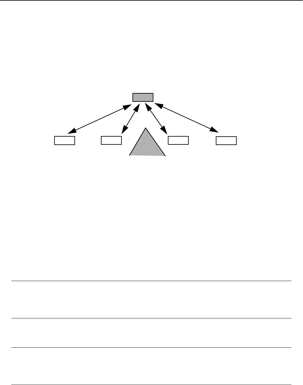
Configuration
82 AWE 120-58 Installation & Configuration Guide
A repeater is used to bypass obstacles that block the RF path (for example, a mountain). When a base station
is set to repeater mode (Repeater Mode = on), it can pass data from remotes in an RF group to other
remotes in the same group. A system with a repeater is a closed system. Example 3 shows a repeater with
four remotes. All the remotes are in the same RF Group 4, so they can talk to each other via the repeater
base.
Example 3: Repeater Configuration (Closed System)
Closed remote units (RF Group = 0) can be combined with open remote units (RF Group = non-zero) within
the same system. In this case each group in the system behaves according to its RF Group characteristics:
closed remotes could communicate only with the base, remotes with the same (non-zero) group number
could communicate with each other, and remotes with different (non-zero) group numbers could not
communicate with each other. A base or repeater would not pass packets originating from a closed remote.
The following table summarizes the first three situations.
In a mixed system, each RF group behaves according to the RF Group charactersitics assigned to it (0 =
closed , 1–63 = open; same non-zero group number = communication, different non-zero group number =
no communication).
Repeater Mode
(Base only)
RF Group
(Remote only)
System
Type System Characteristics
Repeater Mode =
off
1–63 Open Remotes can communicate directly with
the base and each other if remotes that
have the same non-zero RF group number
(if a LOS RF path can be established)
Repeater Mode =
off
0 Closed Remotes can communicate only with the
base station—they cannot talk to each
other
Repeater Mode =
on
1–63 Closed Remotes cannot communicate directly with
each other, they can only communicate via
the repeater base with other remotes that
have the same RF group number
Closed
Remote Remote
Base
System
Repeater
Mode = on
RF Group = 4RF Group = 4
Remote
RF Group = 4
Remote
RF Group = 4
n = 1 – 63 n = 1 – 63 n = 1 – 63 n = 1 – 63
Mountain
No direct communcation
possible due to obstacle

Radio Module Configuration
APR 2001 Rev 03 83
➧ To set remote unit RF group
1. From the Main Menu, select RF Module Configuration and press Enter. The g menu is displayed.
2. Select Remote Unit RF Group and press Enter. The data field highlights.
3. In the Remote Unit RF Group entry field, type the RF group number, using the following table as a guide.
4. Press Enter. The new setting is displayed in the "New" column.
5. Select Reboot New RF Configuration and press Enter. The unit reboots and the AWE 120-58
Login menu is displayed. The unit now runs using the "Current" remote unit RF group for the amount
of time specified by Config Test Minutes.
6. To save the current setting(s) to FLASH, log in, go to the Main Menu, and select Radio Module
Configuration, Save Current Config to Flash. See Rebooting and Saving RF Module
Configurations, page 84.
7. Press Esc to exit to the Main Menu.
Radio Module Configuration
New Current Flash
Station Type Remote Unit Remote Unit Remote Unit
Station Rank (1-1000) 1 1 1
Center Frequency (57410-58338) 5.7874 GHz 5.7874 GHz 5.7874 GHz
Security Password 1 (Hex) 1 1 1
Security Password 2 (Hex) 10 10 10
Security Password 3 (Hex) 100 100 100
Security Password 4 (Hex) 1000 1000 1000
Security Password 5 (Hex) 10000 10000 10000
Scrambling Code (Hex) 0 0 0
Acquisition Code (0-15) 1 1 1
Config Test Minutes (1-120) 30 30 30
Tx Power Level Adjust 0 dB 0 dB 0 dB
Base Station Only Parameters
Repeater Mode off off off
System Symmetry Type Asymmetric Asymmetric Asymmetric
Dynamic Polling Level (1-100) 1 1 1
Remote Station Only Parameters
Remote Unit RF Group (0-63) -> 0 0 0
Reboot New RF configuration Press Enter to Execute
Save Current Config to Flash Press Enter to Execute

Configuration
84 AWE 120-58 Installation & Configuration Guide
Rebooting and Saving RF Module Configurations
Because changes to radio module configuration settings can affect service in a wireless system, changes are
made in three progessive stages: new, current, and flash.
A reboot of a unit is required to save New settings as Current settings. If Current settings are valid (and do
not disrupt the system), they can be saved to Flash memory. If the changes disrupt the system, the original
configuration will be restored automatically when the Config Test Minutes period expires.
➧ To reboot a unit
1. From the Main Menu, select Radio Module Configuration and press Enter. The Radio Module
Configuration menu is displayed.
2. Select Reboot New RF configuration and press Enter. The unit reboots with the with new
settings and with the Config Test Minutes timeout period in effect. The new settings can be viewed in the
"Current" column of the Radio Module Configuration menu. The old, last-saved configuration remains
in Flash memory.
If the configuration is the one you want and the unit operates as intended, you can save the current
changes to "permanent" flash memory by selecting Save Current Config to Flash from the
Radio Module Configuration menu. When you save the current settings to "Flash" the new settings
overwrite the old flash memory settings.
New Intended configuration changes. Temporary memory storage.
Current Configuration actually running on the unit. Temporary memory storage.
Flash Configuration stored in FLASH memory. Long-term memory storage.
Radio Module Configuration
New Current Flash
Station Type Remote Unit Remote Unit Remote Unit
Station Rank (1-1000) 1 1 1
Center Frequency (57410-58338) 5.7874 GHz 5.7874 GHz 5.7874 GHz
Security Password 1 (Hex) 1 1 1
Security Password 2 (Hex) 10 10 10
Security Password 3 (Hex) 100 100 100
Security Password 4 (Hex) 1000 1000 1000
Security Password 5 (Hex) 10000 10000 10000
Scrambling Code (Hex) 0 0 0
Acquisition Code (0-15) 1 1 1
Config Test Minutes (1-120) 30 30 30
Tx Power Level Adjust 0 dB 0 dB 0 dB
Base Station Only Parameters
Repeater Mode off off off
System Symmetry Type Asymmetric Asymmetric Asymmetric
Dynamic Polling Level (1-100) 1 1 1
Remote Station Only Parameters
Remote Unit RF Group (0-63) 0 0 0
Reboot New RF configuration -> Press Enter to Execute
Save Current Config to Flash Press Enter to Execute

Radio Module Configuration
APR 2001 Rev 03 85
➧ To save current configuration to FLASH
1. From the Main Menu, select Radio Module Configuration and press Enter. The Radio Module
Configuration menu is displayed.
2. Select Save Current Config to Flash.
3. Press Enter. The current configuration is saved to flash memory. A reboot is not required. The new flash
memory values are displayed in the "Flash" column of the Radio Module Configuration menu.
Radio Module Configuration
New Current Flash
Station Type Remote Unit Remote Unit Remote Unit
Station Rank (1-1000) 1 1 1
Center Frequency (57410-58338) 5.7874 GHz 5.7874 GHz 5.7874 GHz
Security Password 1 (Hex) 1 1 1
Security Password 2 (Hex) 10 10 10
Security Password 3 (Hex) 100 100 100
Security Password 4 (Hex) 1000 1000 1000
Security Password 5 (Hex) 10000 10000 10000
Scrambling Code (Hex) 0 0 0
Acquisition Code (0-15) 1 1 1
Config Test Minutes (1-120) 30 30 30
Tx Power Level Adjust 0 dB 0 dB 0 dB
Base Station Only Parameters
Repeater Mode off off off
System Symmetry Type Asymmetric Asymmetric Asymmetric
Dynamic Polling Level (1-100) 1 1 1
Remote Station Only Parameters
Remote Unit RF Group (0-63) 0 0 0
Reboot New RF configuration Press Enter to Execute
Save Current Config to Flash -> Press Enter to Execute

Configuration
86 AWE 120-58 Installation & Configuration Guide
RF/Ethernet Statistics
Ethernet and RF statistics are useful for troubleshooting, monitoring link performance, and measuring
throughput. Ethernet and RF statistics are cumulative and increment until reset. The window is view only. See
Resetting Radio and Ethernet Statistics, page 100 for information about resetting RF/Ethernet statistics.
Viewing RF/Ethernet Statistics
➧ To view RF and Ethernet statistics
1. From the Main Menu, select RF/Ethernet Statistics and press Enter. The RF/Ethernet Statistics
window is displayed. The window is view only.
RF/Ethernet Statistics
Ethernet Receive Statistics Ethernet Transmit Statistics
Total Packets Received 0 Total Packets Transmitted 0
Packets For Local Host 0 Packets From Local Host 0
Receive Errors 0 Packets Dropped 0
Packets Dropped 0 Total KBytes Transmitted 0
Packets Discarded 0 Broadcast KBytes Transmitted 0
Total KBytes Received 0
Broadcast KBytes Received 0
RF Receive Statistics RF Transmit Statistics
Total Packets Received 0 Total Packets Transmitted 0
Packets For Local Host 0 Frames From Local Host 0
Packets Dropped 0 Packets Dropped 0
Packets Discarded 0
RF Super Frame Rx Statistics RF Super Frame Tx Statistics
Super Frames Received 0 Super Frames Transmitted 0
Receive Overrun Errors 0
Frame Control Word Errors 0
Header Checksum Errors 0 Throughput Statistics
Packet Control Word Errors 0 Ethernet-to-RF Throughput 0
Super Frame Length Errors 0 RF-to-Ethernet Throughput 0

RF/Ethernet Statistics
APR 2001 Rev 03 87
.
Ethernet Receive
Total Packets Received Number of Ethernet packets from the Ethernet
connection
Packets For Local Host Number of Ethernet packets received from the Ethernet
connection which were destined for the AWE 120-58
unit’s TCP/IP stack
Receive Errors Number of Ethernet packets received with errors, for
example, runt (smaller than 64 bytes), jabber (larger than
1518 bytes), or overflow error
Packets Dropped Number of Ethernet packets dropped because the
wireless link is at capacity
Packets Discarded Number of Ethernet packets discarded as the result of
filtering
Total KBytes Received Total number of kbytes received from the Ethernet port
(broadcast and non-broadcast packets)
Broadcast KBytes
Received
Number of kbytes received from the Ethernet port
(broadcast packets only)
RF Receive
Total Packets Received Number of Ethernet packets received over RF
Packets For Local Host Number of Ethernet packets received over RF and
destined for the local host
Packets Dropped Number of Ethernet packets dropped because the
wireless link is at capacity
Packets Discarded Number of Ethernet packets discarded as the result of
filtering
RF Super Frame Rx
Super Frames Received Number of super frames received
Receive Overrun Errors Number of errors caused by receive buffer overrun
Frame Control Word
Errors
Number of errors caused by frame control word
problems
Header Checksum Word
Errors
Number of errors caused by receiving an invalid header
checksum
Packet Control Word
Errors
Number of errors caused by packet control word
problems
Super Frame Length
Errors
Number of errors caused by receiving an invalid super
frame length

Configuration
88 AWE 120-58 Installation & Configuration Guide
2. Press Esc to exit to the Main Menu.
Ethernet Transmit
Total Packets
Transmitted
Number of Ethernet packets transmitted onto the
Ethernet connection
Packets From Local
Host
Number of Ethernet packets transmitted onto the
Ethernet connection which originated from the AWE unit’s
TCP/IP stack
Packets Dropped Number of Ethernet packets not transmitted due to some
error, for example, unable to transmit within 15 retries or
underflow error
Total KBytes
Transmitted
Total number of kbytes transmitted from the Ethernet port
(broadcast and non-broadcast packets)
Broadcast KBytes
Transmitted
Number of kbytes transmitted from the Ethernet port
(broadcast packets only)
RF Transmit
Total Packets
Transmitted
Number of Ethernet packets transmitted over RF
Frames From Local Host Number of Ethernet packets transmitted to RF from the
local host
Packets Dropped Number of packets dropped because of RF problems
RF S. F. Tx
Super Frames
Transmitted
Number of super frames transmitted
Throughput
Ethernet-to-RF
Throughput
Current data rate measured from wire to air
Resolution = 1 second
RF-to-Ethernet
Throughput
Current data rate measured from air to wire
Resolution = 1 second

System Security
APR 2001 Rev 03 89
System Security
The System Security menu is used to control access to a AWE unit, including the following:
• Restrict access to a unit’s Main Menu with passwords
• Restrict SNMP read and write access with SNMP Community Name
• Enable or disable remote access via Ethernet
• Enable or disable remote access via a wireless link
• Determine the amount of time that a unit remains idle before it automatically logs out.
Viewing System Security
➧ To view system security settings
1. From the Main Menu select System Security and press Enter. The System Security menu is
displayed.
SNMP Community Name 1 Controls SNMP access to the AWE
Read access only
SNMP Community Name 2 Controls SNMP access to the AWE
Read and write access
Change User Password Changes user password to enable access to main menu
Read access only
Change Supervisor
Password
Changes supervisor password to enable access to main
menu. Read and write access
Ethernet Access to
Local Host
Allows remote access to unit to change configuration
settings via wire link with telnet or SNMP
System Security
SNMP Community Name 1 -> public
SNMP Community Name 2 netman
Change User Password Press Enter to change password
Confirm User Password Press Enter to confirm password
Change Supervisor Password Press Enter to change password
Confirm Supervisor Password Press Enter to confirm password
Ethernet Access to Local Host on
Wireless Access to Local Host on
Auto Logout Minutes (1-120) 10

Configuration
90 AWE 120-58 Installation & Configuration Guide
2. Press Esc to exit to the Main Menu.
Wireless Access to
Local Host
Allows remote access to unit to change configuration
settings via RF link with telnet or SNMP
Auto Logout Minutes Maximum time the system can remain idle before the
configuration menus close and the Login menu reappears

System Security
APR 2001 Rev 03 91
Assigning Community Names
Community names can be used to control SNMP access to the AWE. Community Name 1 has read only
access, and Community Name 2 has both read and write access. An SNMP manager can access and configure
any AWE unit on the network as long as the unit has the correct community names and remote access is
enabled (see Allowing Remote Access and Configuration, page 94)
.
➧ To assign community names
1. From the Main Menu, select System Security and press Enter. The System Security menu is
displayed.
2. Select SNMP Community Name 1.
3. Type in name. (Valid community names are assigned using SNMP software.)
4. Press Enter. The new name appears in the entry field.
5. Select SNMP Community Name 2.
6. Type in name. (Valid community names are assigned using SNMP software.)
7. Press Enter. The new name appears in the entry field.
8. Press Esc to exit to the Main Menu.
WARNING
Default community names are presented in all Installation and Configuration guides
distributed by Wi-LAN. It is the responsibility of the customer to ensure that default
community names are changed to unique names at installation. Record all community
name changes.
Community name Privileges Default value
SNMP Community Name 1 Read public
SNMP Community Name 2 Read and Write netman
System Security
SNMP Community Name 1 -> public
SNMP Community Name 2 netman
Change User Password Press Enter to change password
Confirm User Password Press Enter to confirm password
Change Supervisor Password Press Enter to change password
Confirm Supervisor Password Press Enter to confirm password
Ethernet Access to Local Host on
Wireless Access to Local Host on
Auto Logout Minutes (1-120) 10

Configuration
92 AWE 120-58 Installation & Configuration Guide
Setting Menu Passwords
You can use passwords to control access to the Main Menu. The default passwords are user, which allows
you to read configuration settings and supervisor, which allows you to change configuration settings.
➧ To change the user password
1. From the Main Menu, select System Security and press Enter. The System Security menu is
displayed.
2. Select Change User Password and press Enter. The data field highlights.
3. Type the new password and press Enter.
4. Select Confirm User Password and press Enter. The data field highlights.
5. Re-type the new password and press Enter. The change is saved when appears beside the
confirmation field.
6. Press Esc to exit to the Main Menu.
WARNING
The default passwords are printed in all customer documents distributed by Wi-LAN. It
is the responsibility of the customer to change the default passwords to unique
passwords during installation. Record all password changes. When you restore factory
configurations, the login passwords revert to the defaults.
System Security
SNMP Community Name 1 public
SNMP Community Name 2 netman
Change User Password -> Press Enter to change password
Confirm User Password Press Enter to confirm password
Change Supervisor Password Press Enter to change password
Confirm Supervisor Password Press Enter to confirm password
Ethernet Access to Local Host on
Wireless Access to Local Host on
Auto Logout Minutes (1-120) 10
Success

System Security
APR 2001 Rev 03 93
➧ To change the supervisor password
1. From the Main Menu, select System Security and press Enter. The System Security menu is
displayed.
2. Select Change Supervisor Password and press Enter. The data field highlights.
3. Type the new password and press Enter.
4. Select Confirm Supervisor Password entry field and press Enter.
5. Re-type the new password and press Enter. The change is saved when appears beside the
confirmation field.
6. Press Esc to exit to the Main Menu.
System Security
SNMP Community Name 1 public
SNMP Community Name 2 netman
Change User Password -> Press Enter to change password
Confirm User Password Press Enter to confirm password
Change Supervisor Password Press Enter to change password
Confirm Supervisor Password Press Enter to confirm password
Ethernet Access to Local Host on
Wireless Access to Local Host on
Auto Logout Minutes (1-120) 10
Success
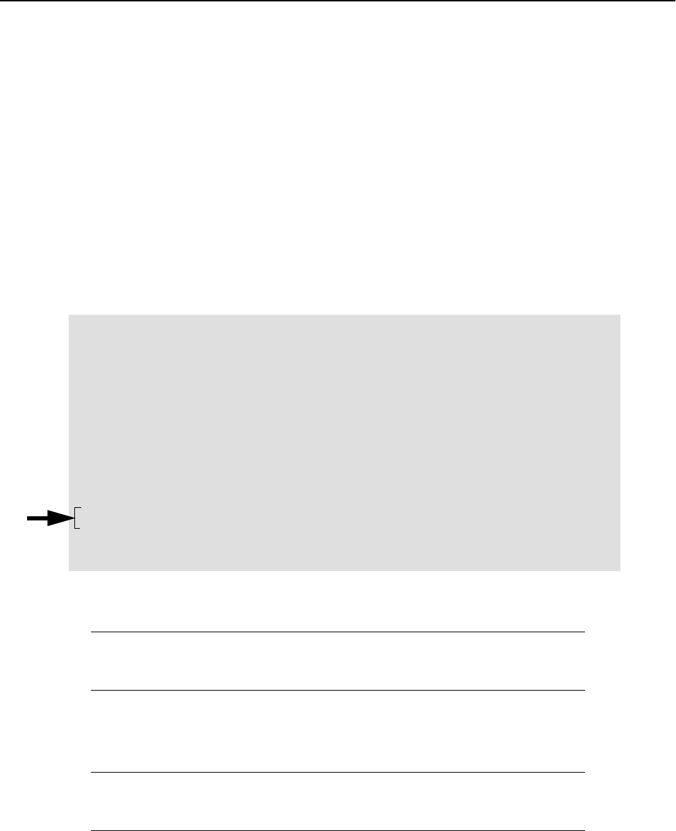
Configuration
94 AWE 120-58 Installation & Configuration Guide
Allowing Remote Access and Configuration
One way to control remote access to a unit’s configuration menu is by restricting the type of link that can be
used to make remote configuration changes. The default setting is to allow remote configuration changes with
both wired and wireless links using telnet or SNMP. However, you can enable or disable the type of link
independently with two settings: Ethernet Access to Local Host and Wireless Access to Local Host.
Note: Data will pass as usual between both units. These two settings only restrict remote access to the unit’s
configuration menu, depending on the type of link that exists between the remote terminal and the
unit–wired or wireless. Also, you cannot "ping" a unit if the link is disabled.
➧ To enable Ethernet and wireless access
1. From the Main Menu, select System Security and press Enter. The System Security menu is
displayed.
2. Select Ethernet Access to Local Host and press Enter. The data field highlights.
3. Select the desired setting, where:
4. Press Enter. The new value appears in the field.
5. Select Wireless Access to Local Hostand press Enter. The data field highlights.
6. Select the desired setting where:
7. Press Enter. The new value appears in the field.
8. Press Esc to exit to the Main Menu.
on Enable configuration changes to the unit via the Ethernet
off Disable configuration changes to the unit via the Ethernet
on Enable configuration changes to the unit via the air
off Disable configuration changes to the unit via the air
System Security
SNMP Community Name 1 public
SNMP Community Name 2 netman
Change User Password Press Enter to change password
Confirm User Password Press Enter to confirm password
Change Supervisor Password Press Enter to change password
Confirm Supervisor Password Press Enter to confirm password
Ethernet Access to Local Host -> on
Wireless Access to Local Host on
Auto Logout Minutes (1-120) 10

System Security
APR 2001 Rev 03 95
Setting the Auto Logout Minutes
You can specify the maximum time the system can remain idle before the configuration menus close and the
Login menu reappears. This feature ensures that the configuration menus close if a user forgets to exit.
Note: When the menus automatically timeout, the system may appear to be frozen. Press Enter to view the
Login menu, where you can login to the Main Menu.
➧ To set the automatic logout timeout period
1. From the Main Menu, select System Security and press Enter. The System Security menu is
displayed.
2. Select Auto Logout Minutes and press Enter. The data field highlights.
3. Type the maximum idle time period in minutes that can pass before the configuration menus close.
4. Press Enter. The new value appears in the field.
5. Press Esc to exit to the Main Menu.
System Security
SNMP Community Name 1 public
SNMP Community Name 2 netman
Change User Password Press Enter to change password
Confirm User Password Press Enter to confirm password
Change Supervisor Password Press Enter to change password
Confirm Supervisor Password Press Enter to confirm password
Ethernet Access to Local Host on
Wireless Access to Local Host on
Auto Logout Minutes (1-120) -> 10

Configuration
96 AWE 120-58 Installation & Configuration Guide
System Commands
System image files contain the software that runs the unit. When you first power up the AWE unit, it runs
from the factory-image. With the System Commands menu you can choose the image file that a unit uses to
power up, and the image file that a unit uses when rebooted.
Viewing System Command Menu
➧ To view system security settings
1. From the Main Menu, select System Commands and press Enter. The System Commands menu is
displayed.
2. Press Esc to exit to the Main Menu.
Default System Image Default image file used at power up
Reboot a System Image Choose the image from which to reboot
Reboot Current Image Reboot unit from the current image
Restore Factory Config
and Reboot
Restore unit to default factory configuration and reboots unit
Reset Radio Statistics Reset RF statistics
Reset Ethernet
Statistics
Reset Ethernet statistics
System Commands
Default System Image -> FACTORY-IMAGE
Reboot a System Image FACTORY-IMAGE
Reboot Current Image Press Enter to Execute
Restore Factory Config and Reboot Press Enter to Execute
Reset Radio Statistics Press Enter to Execute
Reset Ethernet Statistics Press Enter to Execute

System Commands
APR 2001 Rev 03 97
Setting Default System Image
The default image is the image file that a unit uses when it powers up. If you have more than one image saved
on a unit, you can choose the default power up file.
➧ To set the default image
1. From the Main Menu, select System Commands and press Enter. The System Commands menu is
displayed.
2. Select Default System Image and press Enter. The data field highlights.
3. Scroll to select the image to use as the default.
4. Press Enter. The name of the new image file appears in the field. The image will be used the next time the
AWE is powered up.
5. Press Esc to exit to the Main Menu.
System Commands
Default System Image -> FACTORY-IMAGE
Reboot a System Image FACTORY-IMAGE
Reboot Current Image Press Enter to Execute
Restore Factory Config and Reboot Press Enter to Execute
Reset Radio Statistics Press Enter to Execute
Reset Ethernet Statistics Press Enter to Execute

Configuration
98 AWE 120-58 Installation & Configuration Guide
Setting the Reboot System Image
You can choose the system image that a unit uses when it is rebooted.
➧ To choose the reboot image
1. From the Main Menu, select System Commands and press Enter. The System Commands menu is
displayed.
2. Select Reboot a System Image and press Enter. The data field highlights.
3. Scroll to select the image to use when rebooting.
4. Press Enter. The name of the image file appears in the field. This image will be used the next time the
AWE is rebooted.
5. Press Esc to exit to the Main Menu.
Rebooting the Current Image
The Reboot Current Image command can be used when the IP address is changed. See Setting the Internet IP
Address, page 43.
➧ To reboot the current image
1. From the Main Menu, select System Commands and press Enter. The System Commands menu is
displayed.
2. Select Reboot Current Image and press Enter. The AWE reboots using the current image.
System Commands
Default System Image FACTORY-IMAGE
Reboot a System Image -> FACTORY-IMAGE
Reboot Current Image Press Enter to Execute
Restore Factory Config and Reboot Press Enter to Execute
Reset Radio Statistics Press Enter to Execute
Reset Ethernet Statistics Press Enter to Execute
System Commands
Default System Image FACTORY-IMAGE
Reboot a System Image FACTORY-IMAGE
Reboot Current Image -> Press Enter to Execute
Restore Factory Config and Reboot Press Enter to Execute
Reset Radio Statistics Press Enter to Execute
Reset Ethernet Statistics Press Enter to Execute

System Commands
APR 2001 Rev 03 99
Restoring Factory Configurations
If necessary, you can restore the unit to its original factory configuration. This command puts the unit into a
known state, which can help you when troubleshooting, and also provides an easy way to remove custom
configuration settings when you deinstall a unit.
➧ To restore the factory configuration
1. From the Main Menu, select System Commands and press Enter. The System Commands menu is
displayed.
2. Select Restore Factory Configuration and Reboot and press Enter. The unit’s
configuration is restored to the original factory settings.
IMPORTANT
When you restore factory configurations, the login passwords reset automatically to
default values (user and supervisor).
System Commands
Default System Image FACTORY-IMAGE
Reboot a System Image FACTORY-IMAGE
Reboot Current Image Press Enter to Execute
Restore Factory Config and Reboot -> Press Enter to Execute
Reset Radio Statistics Press Enter to Execute
Reset Ethernet Statistics Press Enter to Execute

Configuration
100 AWE 120-58 Installation & Configuration Guide
Resetting Radio and Ethernet Statistics
The statistics displayed in the RF/Ethernet Statistics window are cumulative, but can be reset to track specific
events and for troubleshooting. (See Viewing RF/Ethernet Statistics, page 86 for information about viewing the
statistics). For example, a suspected RF problem can be diagnosed by resetting the radio statistics and
simulating the situation suspected of causing the problem.
➧ To reset radio statistics
1. From the Main Menu, select System Commands.The System Commands menu is displayed.
2. Select Reset Radio Statistics and press Enter. The radio statistics in the RF/Ethernet Statistics
window reset to 0 when appears beside the enter field.
3. Press Esc to exit to the Main Menu.
To reset Ethernet statistics
1. From the Main Menu, select System Commands. The System Commands menu is displayed.
2. Select Reset Ethernet Statistics and press Enter. The Ethernet statistics in the RF/Ethernet
Statistics window are reset to 0 when appears beside the enter field.
3. Press Esc to exit to the Main Menu.
System Commands
Default System Image FACTORY-IMAGE
Reboot a System Image FACTORY-IMAGE
Reboot Current Image Press Enter to Execute
Restore Factory Config and Reboot Press Enter to Execute
Reset Radio Statistics -> Press Enter to Execute
Reset Ethernet Statistics Press Enter to Execute
Success
System Commands
Default System Image FACTORY-IMAGE
Reboot a System Image FACTORY-IMAGE
Reboot Current Image Press Enter to Execute
Restore Factory Config and Reboot Press Enter to Execute
Reset Radio Statistics Press Enter to Execute
Reset Ethernet Statistics -> Press Enter to Execute
Success

Link Monitor Display
APR 2001 Rev 03 101
Link Monitor Display
Viewing Link Monitor Statistics
Link performance statistics such as envelope power, correlation power and bit error rate can be viewed while
the link monitor is running. Statistics are only available on the unit running the link monitor test. The window
is view only.
➧ To view link monitor statistics
1. From the Main Menu, select Link Monitor Display. The RF Link Monitor Statistics window is
displayed. The window is view only.
Link Monitor Rank When run from on the base unit, it is the rank number of
the remote unit whose link is being tested
When run from the remote unit, this field is zero, the
rank number of the base
Base to Remote BER Bit error rate from the base to the remote. Displays “N/
A” when the link monitor is not running
Remote to Base BER Bit error rate from the remote to the base. Displays
“N/A” when the link monitor is not running
Missed Packet Count Number of missed packets
Base to Remote Env Power Envelope power received at the remote (including noise,
measured in dB).
Base to Remote Corr Power Correlation power received at the remote (excluding
noise, measured in dB).
Remote to Base Env Power Envelope power received at the base (including noise,
measured in dB).
Remote to Base Corr Power Correlation power received at the base (excluding noise,
measured in dB)
RF Link Monitor Statistics
Link Monitor Rank 0
Base to Remote BER N/A
Remote to Base BER N/A
Missed Packet Count 0
Base to Remote Env Power 0
Base to Remote Corr Power 0
Remote to Base Env Power 0
Remote to Base Corr Power 0
Configuration
102 AWE 120-58 Installation & Configuration Guide
Logout
Logging Out
There are two ways to log out of the main menu.
➧ To log out of the Main Menu
From the Main Menu, select Logout and press Enter.
or
1. Press the Esc key on the keyboard until you reach the wilan command line.
2. Type logout at the wilan> prompt.
3. Press Enter to log out.
Setting Operating Mode with the Mode Button
The operating mode of a unit is usually selected from the RF Station Configuration menu (see Setting the
Operating Mode, page 51). However, operating mode can also be set using the Mode button located on the
back panel of the AWE 120-58. When you select an operating mode, the color of the Mode LED indicates the
operating mode and the color of the Air LED indicates whether a unit is transmitting, receiving, or listening.
The AWE starts up in Normal operating mode and the Mode LED is OFF. The following modes are available.
Mode Function Mode LED
Normal Mode Transmit and receive in both directions—normal operating mode
See Performing Link Monitor Test (Normal Mode), page 54
OFF
Transmit Test Transmit only
See Performing Transmit and Receive Tests, page 57
Red
Receive Test Receive only
See Performing Transmit and Receive Tests, page 57
Green
RSSI Test Received Signal Strength Indicator. Indicates fade margin data on
the Air LED
See Performing the RSSI Test, page 59
Orange
Enter ESC to return to Main Menu
wilan> logout
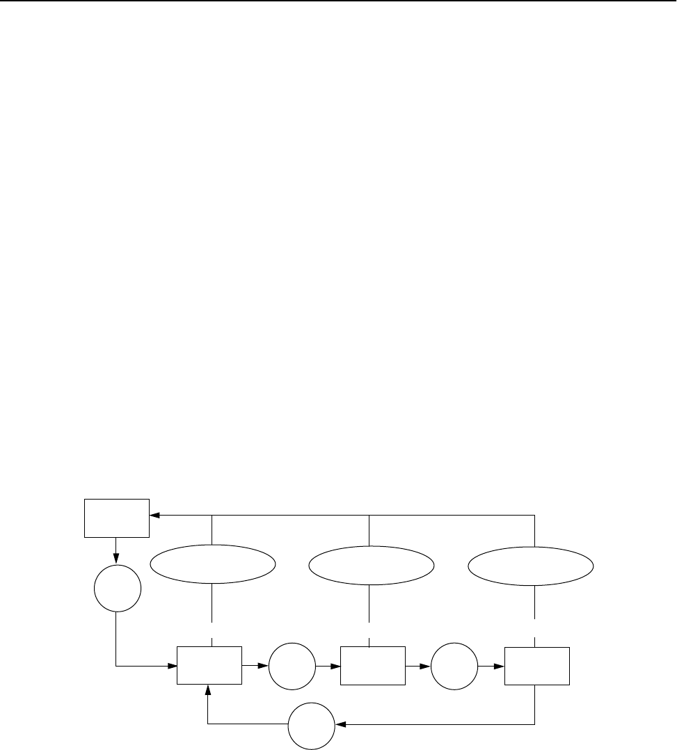
Setting Operating Mode with the Mode Button
APR 2001 Rev 03 103
Selecting RF Tests with the Mode Button
You can use the Mode button at the back of the unit to select and run RF tests. (The other method of running
RF tests is with the RF Station Configuration menu. See Setting the Operating Mode, page 51 for more
information about running tests from a menu.)
➧ To select the operating mode with the mode button
1. Press the Mode button once and release it quickly. The unit goes to Transmit Test mode. Mode LED =
Red.
2. Press the Mode button once and the unit goes to Receive Test mode.
Mode LED = Green.
3. Press the Mode button once and the unit goes to RSSI Test mode.
Mode LED = Orange.
4. Press the Mode button once and the unit returns to Transmit Test mode.
Mode LED = Red.
5. To return to Normal Mode after any test, press the Mode button and release it after at least two
seconds. The Air LED and Mode LED both turn orange when the button has been held long enough, and
the Mode LED turns OFF.
Mode Button Operation
Note: If you do not manually return the unit to Normal Mode, the unit will automatically reboot and return
to Normal Mode when the end of the test time period time is reached. The test time period cannot be
set with the Mode button—you must use the RF Station Configuration menu to set the test mode
timer minutes (see Setting Config Test Minutes, page 67).
Normal
Mode
press
once
press
once
Tx Test Rx Test
press
once
press
once RSSI
Test
Mode LED =OFF Air and Mode LED
turn orange
Mode LED =orange
press and hold
for two seconds
Mode LED =green
Mode LED = red
press and hold
for two seconds
press and hold
for two seconds
Configuration
104 AWE 120-58 Installation & Configuration Guide
Command Line Interface
You can perform some basic commands with the command line interface. Type commands from the prompt.
➧ To use the command line interface
1. Log in to the AWE unit. The Main Menu is displayed.
2. Press Esc. The wilan> prompt appears.
3. Type the command after the prompt and press Enter.
4. Press Esc to return to the Main Menu.
The following are some commands you can run with the command line interface.
Command Action Example
help show the following command summary
list:
menu cls dir del ping
logout exit quit
wilan>help menu
menu return to the configuration menus wilan>menu
cls clear the terminal screen wilan>cls
dir show a file directory wilan>dir
del delete a file wilan>del sample.txt
ping ping a remote IP address wilan>ping
198.168.200.5
logout log out of the command line interface
or
terminate a remote telnet session
wilan>logout
exit log out of the command line interface
or
terminate a remote telnet session
wilan>exit
quit log out of the command line interface
or
terminate a remote telnet session
wilan>quit
wilan>

APR 2001 Rev 03 105
Troubleshooting
Administrative Best Practices
By performing some administrative best practices and preventative maintenance, you can prevent many
problems with your system, or become aware of minor problems before they become serious ones.
Wi-LAN recommends the following practices.
• Maintain the integrity of the system design when adding or changing a system. The introduction of
new elements to a system can cause problems unless the network plan is revised to take into account
the changes. For example, improper installation of a co-located antenna can add unwanted system
interference.
• Measure and document system performance at the time of the original installation.
• Monitor system performance regularly. Environmental change as well as normal wear and tear on
components can affect system performance.
• Perform preventative maintenance every 6 months. See Preventative Maintenance and Monitoring, page
31 for information.
• After periods of extreme weather, perform link monitor tests to verify the system; inspect towers,
antennas, cables and connectors for damage.
• Change menu passwords so that only key personnel can reconfigure the system. See Setting Menu
Passwords, page 92.
• Keep records of recent changes. Especially document the addition of units, hardware and software
changes and changes to configuration settings. Configuration errors often cause other problems.
Current records can be compared with original installation records and function as a benchmark to
help you troubleshoot.
• Keep a log of past and present problems and solutions. Store the log on-site, if possible. The log
identifies common failure points and fixes.
• Before contacting Wi-LAN for customer support, document the symptoms of the problem and the
steps taken to diagnose and fix the problem. Record the current configuration of the system.

Troubleshooting
106 AWE 120-58 Installation & Configuration Guide
Troubleshooting Areas
There are five key areas to be aware of when troubleshooting.
Network Integrity: Continued performance and reliability of a network depends upon maintaining the
integrity of the network. If you change a network’s design, you will affect its operation. Be aware of recent
changes to your network.
Quality of RF link: Data communication depends first on the quality of the RF link. If you can establish and
maintain a high-quality RF link, then you can be sure the link will carry high-speed data. If the quality of the RF
link is degraded for some reason, the quality of the transmitted data will also degrade.
Radio Hardware:There are three basic parts to a AWE: radio unit, antenna feed (cable, connectors, surge
suppressors, patch cables etc.) and antenna. You can isolate faulty hardware using measurement and/or
replacement methods.
• Verify the radio unit with diagnostic tests (such as RSSI and link monitor tests), bench test a unit, or
replace a unit.
• Verify the antenna feed with a Site Master test set. Sweep cables, connectors and lightning suppressors,
or exchange these parts for known good parts.
• To verify the antenna you can sweep the antenna with the Site Master test set or exchange the antenna.
Correct Unit Configuration: Units must be configured correctly, according to the network plan.
Configuration errors can cause an inability to communicate or poor performance. The addition of units or
changes to your system may require you to change configuration settings.
Embedded Software: Operate with a proven software image. Download new software if you suspect that
a unit’s software is corrupted.
The following chart provides answers to some of the more common problems that can occur when installing
and using a AWE bridge.

Troubleshooting Areas
APR 2001 Rev 03 107
Troubleshooting Chart
Indication Possible Cause Suggested Corrective Actions
High BER Signal strength is too low Perform RSSI test to determine fade margin
Align or change antennas or cables
Ensure LOS between antennas
Signal strength is too high Adjust antennas
Increase distance between units
Interference Change center frequency
Increase RF power
Change polarization of antennas
Physically isolate antenna from source of
interference or change physical location of
antenna
Bad radio (Tx/Rx) Bench test radio
Exchange radio
Bad antenna Visually inspect antenna for damage
Sweep antenna
Replace antenna
Bad cable Visually inspect cable
Replace cable
Bad connectors Visually inspect connectors
Replace cable/connectors
Noisy power supply Replace power supply unit
Temperature Determine ambient operating temperature is
too high or low
Increase or reduce ambient temperature.
Low signal strength/
fade margin
Bad radio Bench test radio
Replace radio
Bad antenna Visually inspect antenna for damage
Sweep antenna
Replace antenna
Poor antenna alignment Use RF diagnostics to re-align antenna
Bad cable Visually inspect cables/connectors
Replace cable/connectors
Bad surge suppressor Use voltmeter to check for open circuit
Replace surge suppresso.
Incorrect radio configuration Bench test radio to confirm configuration
Reconfigure radio

Troubleshooting
108 AWE 120-58 Installation & Configuration Guide
Indication Possible Cause Suggested Corrective Actions
No Fresnel zone clearance Increase antenna height to obtain clearance
Relocate antenna
Remove obstacles to LOS (line of sight)
Use repeater base configuration
Power supply problems Try a different AC circuit
Measure the power at the AC outlet
Measure the output from the power supply unit
Replace the power supply unit
High packet loss Signal strength too low Check for LOS between antennas
Check for obstacles in RF path
Check for interference
Realign antennas
Replace antenna
Interference Change center frequency
Increase RF power
Change polarization of antennas
Physically isolate antenna from source of
interference or change physical location of
antenna
Multipath interference Realign antennas
Relocate radio/antenna
Temperature Determine if ambient operating temperature is
too high or low
Increase or reduce ambient temperature
No communication
between units
Configuration problems Check the following configuration settings:
Rank number–Each unit must have a unique rank
number. Base station rank or remote rank may
be incorrect
Access code–Only units with same access code
can communicate
Scrambling code–Base station and remote units
must use same scrambling codes to decode
messages
Acquisition code–All units must have same
acquisition code to communicate
Center frequency–Units must have same center
frequency to communicate

Troubleshooting Areas
APR 2001 Rev 03 109
Indication Possible Cause Suggested Corrective Actions
IP address/subnet mask–Incorrectly configured
IP addresses will result in units being unable to
communicate
Check that IP addresses are unique for each unit
within a subnet and the correct subnet mask is
being used
Antenna or cable failure or
damage
Visually inspect antenna and cables for damage
Sweep antenna and cables
Replace antenna or cables
Poor link
performance
Polling sequence Check polling round number. Higher polling
round number increase the delay between polls
for less active units
Distance Check the maximum remote distance
configuration setting
No LOS Check LOS between antennas
Excessive Bit errors and
processing errors
Multipath interference–align or relocate
antennas or radio
Signal absorption Check LOS for obstacles such as trees
Throttling level Check if throttling is correctly configured
(Control throttling by enabling or disabling
throttling and by modifying the throttling index)
Center frequency Set units from different systems in the same
geographic area to different center frequencies–
overlapping wavelengths from other systems will
degrade performance
Overpowering co-located
unit
Output power from one unit can overpower
another co-located radio, even if units operate
on different channels—lower unit power
SNMP can’t be
activated
IP filtering configured
incorrectly for SNMP
Change IP filtering to enable SNMP
Unable to access
main configuration
menu
Invalid passwords Contact Wi-LAN for information about how to
re-enter your system
Units will need to be reset

Troubleshooting
110 AWE 120-58 Installation & Configuration Guide
Indication Possible Cause Suggested Corrective Actions
Unit will not operate Faulty unit Bench test unit
Corrupt unit software Reload unit software
Point-point link is too
slow
Throttling level Check if throttling is correctly configured
Center frequency Set units from different systems in the same
geographic area to different center
frequencies—overlapping wavelengths from
other systems will degrade performance
Overpowering co-located
unit
Output power from one unit can overpower
another co-located radio, even if units operate
on different channels
Lower the power of the unit

APR 2001 Rev 03 111
Appendix A: Planning Your Wireless Link
To ensure an effective and reliable wireless link, you first need to perform some network planning. This
section provides some general guidelines for planning a wireless link, including the following:
• Planning the physical layout of your system
• Determining antenna and cable requirements
• Determining configuration settings for units
• Calculating a link budget
Planning the Physical Layout
You need to plan the physical layout of your wireless system.
• Determine the number of remotes
• Ensure LOS (line-of-sight) exists between units and determine coverage areas
• Measure the distance between the base station and each remote unit
• Consider the need for equipment shelters, electrical power and environmental requirements
Determine the Number of Remotes
Since the 12 Mbps data rate is shared between all units, the fewer the number of remote units, the faster each
wireless link. Although a maximum of 1000 remotes is supported per base station, this number would result
in low data rates. Instead, to ensure high data rates, Wi-LAN suggests a standard where 75 remotes can
maintain constant 128 kbps communication with a base station. Since it is unlikely that all units will be active
at the same time, the total number of remotes for planning purposes can be increased by a factor of three, so
that a maximum of 225 (3 x 75) remotes per base station is recommended. This should enable all users to
easily achieve 128 kbps performance.
Ensure LOS and Determine Coverage Area
Ensure the availability of a clear, LOS (line-of-sight) radio path between base station and all its remotes. Plot
the coverage area of each base station on a map, and determine which base station will service which remote
unit. Plan some alternate links in case base station coverage areas overlap or if physical obstacles block the
radio path to some remotes.

Appendix A: Planning Your Wireless Link
112 AWE 120-58 Installation & Configuration Guide
Measure the Distance Between Units
Use a mapping method or GPS (global positioning system) to measure the distance between the base station
and each remote, and check the radio path to identify any obstructions in the LOS path between the two
antennas. Due to the high frequency and low output power permitted in the ISM bands, no obstructions can
exist between the base station and the remote unit.
Determine Shelter, Power and Environmental Requirements
AWE units must be located in a weatherproof environment (a room, EMS cabinet or shelter) with an ambient
temperature between 0º and 40º Celsius, and humidity from 0 to 95% non-condensing. Consider building,
electrical power, heating and air conditioning requirements.
Determining Antenna
and Cable Requirements
The signal from an indoor antenna can penetrate several walls, although metal obstructions or building
features such as elevator shafts can deflect or inhibit radio waves. On-site testing is advised because all
interiors are unique.
If you plan to install antennas outdoors you need to consider several factors.
• Ensure a clear line-of-sight radio path is available between each remote and its base station.
• Ensure that Fresnel zone clearances are met. Identify obstructions that could degrade link
performance now and in the future.
• Obtain permission from building owners if you intend to install the antenna on a rooftop
• Obtain 24-hour access to antennas, cables and equipment
• Determine antenna mounting positions: the final position should be selected to enable physical
shielding of the antenna at the back and sides from radio interference in the ISM band.
• Consider potential wind load and ice loading impact on the antenna
• Be aware of possible multipath effects: installing an antenna too close to reflective surfaces can cause
signal problems.
• Check local regulatory restrictions, such as height, on antenna mast usage in the identified location
• Ensure that your antenna is properly grounded and installed according to local electrical codes.
• Determine transmission cable lengths and plan cable routes. Minimize the length of the coaxial cable
because the longer the cable, the greater the cable losses.
• Calculate the fade margin—a minimum 15 dB fade margin is required to ensure the reliability of your
wireless link.
• Determine Ethernet cable lengths and plan cable routes.
More information about antennas is provided in Antenna Basics, page 118.
WARNING
Correct antenna installation is critical to the safe operation and performance of your
system. Antennas should always be professionally installed.

Determining Unit Configuration Settings
APR 2001 Rev 03 113
Determining Unit Configuration Settings
Configuration settings of units should be determined before installation to ensure easy installation and to
reduce installation costs. An information sheet should be prepared for each unit that specifies the basic
configuration settings of that unit.
• Unit Name
• IP Address
• Subnet Mask
• Station Type
• Station Rank
• Center Frequency
• Security passwords
• Scrambling Code
• Acquisition Code
• Remote Unit RF Group
• Transmit Power Level
You may also specify other settings such as remote distance, IP filtering and throttling.
Calculating a Link Budget
Proper path planning ensures that each end of the RF link receives sufficient signal power to maintain the
desired Bit Error Rate (BER). The effectiveness and reliability of your RF link depends on several factors.
• Antenna gain and other characteristics
• Distance between antennas and obstructions in the RF path
• Location and height of antennas
• Length and type of coaxial cable connecting the unit to the antenna
These factors are considered when you calculate your link budget. The calculation indicates, on paper, if your
radio link is feasible over a given distance and path and if your RF link meets regulatory requirements. Link
budgets are typically expressed in decibels (dB).
The following variables are used to calculate the link budget.
Variable Description
System Gain Maximum path loss that the system can support for usable data transmission
EIRP (Effective
Isotropically
Radiated Power)
Power radiating from an antenna taking into account the output power from the
transmitter, connector losses, cable losses and antenna gain
Antenna Gain Gain of the antenna over a dipole (dBd) or theoretical (dBi)
Propagation Loss Signal loss experienced as it travels through the air, expressed in dB

Appendix A: Planning Your Wireless Link
114 AWE 120-58 Installation & Configuration Guide
Each variable is described below.
System Gain
The system gain of a radio system is the difference between the transmitted power and a receiver’s sensitivity
threshold. The system gain of the AWE 120-58 is calculated as follows.
Note: For the sake of simplicity, a Tx Power value of 20dBm is used in the following calculations.
To ensure reliable communications, the system gain plus all antenna gains must be greater than the sum of all
losses. For a reliable link, Wi-LAN recommends that the system gain plus all antenna gains be greater than the
sum of all losses by 15 dB. This amount is the fade margin.
EIRP (Effective Isotropically Radiated Power)
EIRP is the power that radiates from an antenna, taking into account the output power from the transmitter,
the connector and cable losses, and the antenna gain. Unlike the Tx output power of the devices, EIRP takes
account of antenna gain and cable losses. Antennas use directional gain to increase the effective radiated
power. Losses such as cable losses reduce the effective radiated power.
You calculate the EIRP as follows.
Fresnel Radius Distance around line-of-sight that must be clear of obstacles
Cable Loss Signal loss experienced as it passes through the coaxial cable, expressed in dB
Path Loss Total loss from one end of the path to the other. Includes propagation losses,
cable losses and any other losses that impact the system performance
Formula: System Gain = Transmission Power - Receiver Sensitivity @ 10-6 BER
Variables: Tx Power = 20 dBm
Receiver Sensitivity = –80 dBm (receiver sensitivity @ 10-6 BER)
Calculation: 20dBm – (–80) dBm = 100 dB
Formula: EIRP = Tx Power (dBm) - Cable Losses (dB) - Connector Losses (dB) + Antenna Gain (dBi)
Note: The FCC regulatory body has set the EIRP limit to +36 dBm for point-to-multipoint
applications per FCC 15.247(b)(3). For point-to-point applications EIRP can be >36 dBm
as per FCC 15.247(b)(3)(ii).
Visit www.fcc.gov for the most current information.
Industry Canada specifies the EIRP limit to ≤ 4W (+36 dBm) as per RSS-210, 6.2.2(o)(b)
for point-to-multipoint applications and 200W (+23 dBW) for point-to-point applications.
Visit www.ic.gc.ca for the most current information.
Variable Description

Calculating a Link Budget
APR 2001 Rev 03 115
Antenna Gain
To ensure the best range and interference suppression, the external antenna should be directional, focusing
the radio energy in one direction (toward the other end of the link) rather than onmi-directional. Use of a
directional antenna also reduces interference from other systems operating at the same frequency.
Note: In some situations, you may want to use an omni-directional antenna in your system design. For
example, you would use an omni-directional antenna for a base station with remote sites situated in a
360º path around it.
When you select a Wi-LAN approved antenna, pay particular attention to the gain specification. When you
select an antenna for a remote station, select an antenna with a gain that provides at least 15 dB fade margin.
Antenna gain is specified in either dBi or dBd. When an antenna is specified in dBd, add 2.14 dB to the value
to convert it to dBi.
Propagation Loss
Propagation loss is the attenuation (reduction) in RF signal energy as it travels through space. In most wireless
systems, losses through space are the major contributor to signal attenuation. When you know the intended
installation locations of the base and remote stations, determine the physical line of sight distance and then
calculate the RF attenuation as follows:
Fresnel Zone
It is essential that you locate your antennas at maximum above-ground height to ensure that all ground-based
obstructions are cleared from the Line of Sight path and the Fresnel Zone.
The Fresnel Zone is the expansion of the RF signal radio angles in the vertical plane near the middle of the RF
path.
Fresnel Zone
Formula: Attenuation (dB) for 5.8 GHz band = 108 dB + 20log(dkm)
where:
dkm = Distance in Kilometers
108 dB = Pathloss Constant in the 5.8 GHz band
First Fresnel Zone
Line of Sight
Fresnel Radius
Ground
The maximum
Fresnel Radius
indicates that this
path must be kept
clear of
obstructions.

Appendix A: Planning Your Wireless Link
116 AWE 120-58 Installation & Configuration Guide
For the 5.8 GHz band, the approximate Fresnel Radius is calculated as follows.
Cable Loss
Cable and connector losses affect the operation of the wireless link and therefore should be kept to a
minimum by minimizing cable lengths and carefully selecting the type of cable. The two primary coaxial cable
specifications for the AWE 120-58 are:
• Cable must be 50 ohms nominal impedance
• Cable must be of a low loss type
The following is an example of cable loss ratings at 5.8 GHz.
Note: When you calculate path loss, you will add 1dB at each end of the link to compensate for connector
losses in addition to the cable loss value.
Path Loss
Path loss describes the total RF attenuation throughout the system from Tx antenna to Rx antenna. This
includes the losses as the RF signal travels through space plus Tx and Rx cable loss, and Tx and Rx connector
loss. Use the following formula to calculate path loss.
Once you know the path loss, you can compare the value to the system gain value. If the system gain value is
greater than the path loss, the link is feasible. See System Gain, page 114 for more information about system
gain.
Fade Margin
Fade margin is the amount by which the system gain plus the total antenna gain exceeds the path loss.
As calculated, the fade margin is the number of dB that the received signal strength exceeds the minimum
receiver sensitivity. You require some level of fade margin for any wireless system to compensate for RF path
fading due to weather conditions or multipath interference.
The Wi-LAN recommended fade margin for the AWE 120-58 is a minimum of 15 dB. The sum of the cable
losses, connector losses, propagation losses, and the 15 dB required fade margin should be less than the sum
of the system gain and antenna gain.
Formula: Fresnel Radius (meters)=
Cable Type LDF2-50 LDF4-50A LDF4.5-50
Loss (dB/meter) 0.32 0.22 0.16
Formula: Path Loss = Tx and Rx Cable Loss + Tx and Rx Connector Loss + Propagation Loss
Formula: Total antenna gain = Tx Antenna Gain + Rx Antenna Gain
2.2 dkm dkm 8.12⁄()
2
+

Link Budget Example
APR 2001 Rev 03 117
Link Budget Example
The values for cable and connector losses in this example are only for illustration. You will need to work these
out for your specific installations.
Formulas: System Gain + Antenna Gain ≥ Propagation Loss + Desired Fade Margin +
Cable Losses + Connector Losses
or
Actual Fade Margin ≥ System Gain + Antenna Gain – Propagation Loss
– Cable Losses – Connector Losses
and
Actual Fade Margin ≥ Desired Fade Margin
where:
System Gain = Tx Power – Rx Sensitivity
Antenna Gains = Tx Antenna Gain + Rx Antenna Gain
Cable Losses = Base Cable Losses + Remote Cable Losses
Connector Losses = Base System Connector Losses + Remote System
Connector Losses
Variables: Desired Fade Margin = 15 dB
Tx Power = 20 dBm
Rx Sensitivity = –80 dBm
Tx Antenna Gain = 27 dBi
Rx Antenna Gain = 27 dBi
Propagation Loss for desired range of 10km = 108 + 20 x log(10) = 128 dB
Tx Cable Losses (5m LDF2-50) = 5 * 0.32 = 1.6 dB
Rx Cable Losses (5m LDF2-50)= 5 * 0.32 = 1.6 dB
Tx Connector Losses = 1 dB
Rx Connector Losses = 1 dB
Variable
Calculations:
System Gain = 20 - (–80) = 100 dB
Antenna Gains = 27 + 27 = 54 dBi
Cable Losses = 1.6 + 1.6 = 3.2 dB
Connector Losses = 1 + 1 = 2 dB
Actual Fade
Margin
Calculation:
Actual Fade Margin = 100 + 54 – 128 – 3.2 – 2 = 20.8 dB
Analysis: A goal of Actual Fade Margin ≥ 15 dB is achieved.

Appendix A: Planning Your Wireless Link
118 AWE 120-58 Installation & Configuration Guide
Antenna Basics
Antennas focus and absorb radio energy in specific directions, depending on their design. AWE 120-58
antennas must be tuned to 5.7250 – 5.8500 GHz.
This section contains basic information about antenna parameters and how to select and install antennas for
use in your wireless system. Antenna characteristics, mounting location, and correct operation of antennas
are critical to a wireless link.
Antenna Parameters
Parameter Description
Gain • Antennas have a gain associated with them, which is a measure of their ability to
amplify signals in their tuned band
• Antenna gain is achieved by focusing the signal. A higher gain antenna has a more
compressed signal
dBd vs. dBi • Antenna gain must be measured over a known reference and is often expressed as
either dBd or dBi
• dBd is antenna gain referenced over a half-wave dipole which is an antenna that has a
donut shaped radiation pattern
• dBi is antenna gain referenced over an isotropic radiator which is a theoretical
antenna that radiates equally in all directions (e.g. the sun)
• Wi-LAN references antenna gain in dBi. The conversion factor is 0 dBd = 2.14 dBi
Beamwidth • Describes how a signal spreads out from the antenna, and the range of the reception
area
• Beamwidth is measured between the points on the beam pattern at which the
power density is half of the maximum power. This is often referred to as the –3 dB
points
• A high gain antenna has a very narrow beamwidth and may be more difficult to align
Downtilt or
uptilt
• Some antennas have either an associated downtilt or an uptilt. The tilt further
focuses the signal downward or upward with respect to the horizon
• Tilt may be either electrically built into the antenna or achieved mechanically with
the mounting gear
• Downtilt or uptilt may be required when there is a significant deviation between the
elevation of the remote site(s) and the base site
F/B • Front-to-back ratio
• Directional antennas focus the signal in a forward path. Achieved by directing the
signal in one direction that reduces the signal in the opposite direction
• A higher gain antenna typically has a greater F/B ratio

Antenna Basics
APR 2001 Rev 03 119
Implementation Considerations
Some key items to consider when selecting and installing antennas for your wireless network follow.
XPD • Polarity and Cross-Polarization Discrimination (XPD)
• Antennas have an associated polarity, which is the orientation of the radiating
element with respect to earth
• Antennas are usually described as vertical, horizontal, or circularly polarized. The
polarity of all antennas used in a system must be the same
• Cross-Polarization Discrimination specifies the signal isolation achieved when the
receiving element is perpendicular to the radiating element. Can be advantageous
when co-locating radio systems
VSWR • Voltage standing wave ratio
• VSWR is the voltage ratio of minimum to maximum across a transmission line
• A VSWR of 2.0:1 or less in an antenna is considered effective. Most antennas have a
VSWR of 1.5:1
• For example, when using a radio with a 4 W output with an antenna VSWR of 1.5:1,
the reflected power will be 160 mW
Item Description
Absorption • Antennas mounted too close to “soft” objects, such as trees, may experience a
reduction in signal strength due to absorption
• Absorption is most often encountered in applications installed during the fall or
winter months, and the problem does not become evident until the spring
Diffraction • Diffraction occurs when a radio signal reflects or bounces off of a solid object
• Level of diffraction could lead to connectivity problems if the remaining signal level is
too low
• Two types of diffraction are shadowing and multipath
Shadowing • Shadowing is a form of diffraction that is typically caused when antennas are mounted
too close to a structure and they lose a portion of the signal lobe due to reflection.
The receive antenna is in a shadowed area
• To minimize shadowing, ensure that there is adequate height above structures when
mounting antenna equipment
Multipath
Interference
• Multipath is a form of diffraction in which the reflected signal arrives at the receiver
at different times which confuses the receiver
• Multipath may be interpreted as interference by the receive antenna and can result in
bit errors and processing delays
Parameter Description

Appendix A: Planning Your Wireless Link
120 AWE 120-58 Installation & Configuration Guide
Wi-LAN Approved Antennas
Antennas must be selected from the following list of Wi-LAN approved antennas. Antennas must be
connected using transmission cables having the specified minimum lengths.
There are several factors to consider when choosing the right antenna for a wireless application. The
following are some initial questions you should ask before selecting an antenna.
• What is the operating frequency range?
• Will this be a point-to-point or point-to-multipoint application? Ensure that you consider if the
application will change in the future.
• What are the coverage requirements?
• What is the gain requirement?
• What is the elevation of the remote site(s) with respect to the base station and will additional
downtilt/uptilt be necessary at either the base or remote site to compensate?
• Will there be any obstructions in the path?
• Will systems be co-located? What polarity will be used?
• What are the regional environmental conditions? For example, is there windloading, salt air, excessive
moisture, ice buildup etc.?
• What is the antenna lifetime expectation?
• What are the site and mounting options?
• What are the restrictions in the locale regarding the effective radiated power permitted from the
antenna?
• Will antenna appearance be a factor?
Antenna
Description Number Gain
(dBi)
5.8 GHz Cushcraft directional planar S57212AMP 12 Note: 1 One of the following cables
with the specified minimum length
must be connected to antenna:
5.8 GHz European 55 degree H-sector1SA17-55H/449 17
5.8 GHz European 55 degree V-sector1SA17-55V/450 17
5.8 GHz MTI directional/flat planar MT-10010 32 LMR400 6 m
5.8 GHz MTI directional/lat planar MT-10011 28 LMR600 7 m
5.8 GHz TIL-TEK directional/dish TA-5224M 28.5 LMR900 13 m
5.8 GHz TIL-TEK directional/dish w/radome TA-5224MR 28.5 LDF4-50A 10 m
5.8 GHz TIL-TEKdirectional/dish TA-5248M 34.2 LDF4.5-50 13 m
5.8 GHz TIL-TEK directional/dish w/radome TA-5248MR 34.2
5.8 GHz TIL-TEK directional/dish TA-5272M 37.5
5.8 GHz TIL-TEK directional/dish w/radome TA-5272MR 37.5
Note: Directional antennas may not be used for point-to-multipoint
applications.

Antenna Basics
APR 2001 Rev 03 121
Antenna Installation Factors
Some factors you should consider when installing antennas into your wireless system are listed below.
Factor Description
Maximizing the
AWE 120-58’s
Capabilities
• Minimize obstructions in the radio path
• Line Of Sight (LOS) is crucial for reliability
• Ensure that equipment is installed correctly
• Ensure proper grounding, testing, and alignment of antennas
• Install in environmental conditions that are suitable for the AWE unit
• Select proper antennas and cable for the application
• Ensure sufficient gain for the intended application
Safety • Proper grounding of antenna apparatus in accordance with respective
Electrical Code(s) is crucial
• Wi-LAN recommends using a surge arrestor where the antenna cable
enters the building
• All installations should be completed by a qualified and competent RF
technicial
EIRP • Effective Isotropically Radiated Power (EIRP)
• EIRP is the amount of power that is transmitted to the air from the
antenna
• EIRP levels depend on the power of the radio transmitter, the gain of the
antenna, and the losses incurred in the antenna cable
• EIRP must not exceed 4 W or 36 dBm in Canada and the United States for
point-to-multipoint applications.
Note: EIRP = Power out of unit – Power lost in cable + Gain in power from
Antenna
Fade Margin See Calculating a Link Budget, page 113
LOS • Line of Sight (LOS)
• LOS is a football shaped pattern known as the Fresnel Zone, which must
be kept clear of obstructions. See Fresnel Zone, page 115 for more
information
• Visual line of sight must be achieved. When standing at the antenna
position, you must be able to see the remote antenna

Appendix A: Planning Your Wireless Link
122 AWE 120-58 Installation & Configuration Guide
Minimal Clearance Above Obstructions
For the AWE 120-58, the absolute minimum clearance above obstructions requirements are as follows (in
meters):
@ 5.8 GHz
Some example clearance requirements for 5.8 GHz links follow.
Note: There is also a correction factor to compensate for curvature of the earth. This correction factor is
not required when the correction value is negligible < 10 km.
Installing Antennas
Antennas must be installed professionally to ensure that the antenna operates properly and follows accepted
safety, electrical, grounding and civil engineering standards.
Ensure the following conditions.
• Dipole antennas are oriented vertically (point up).
• Antennas for the system have the same polarity (vertical, horizontal or circular).
• Connectors attaching the coaxial cable to the antenna are properly weatherproofed.
• A drip loop is formed at the building entrance to prevent water flowing down the coaxial cable and
entering the installation building.
• The coaxial cable is secured to the supporting structure at one meter intervals to prevent wind
damage and frost loading problems.
• The antenna is firmly attached to the mast to prevent it from falling, yet has some flexibility so you
can move the antenna to fine-tune its position.
• The coaxial cable is connected to the antenna and to the Antenna port on both sides of the link (base
and remote stations).
• The antennas are grounded properly.
Distance
(km)
Clearance
(m)
Distance
(miles)
Clearance
(ft)
0.5 1.6 0.5 6.5
1 2.2 1 9.3
2 3.2 2 13.3
3 3.9 3 16.7
5 5.2 5 22.6
8 6.9 8 31.3
10 8.0 10 37.3
15 10.8 15 54.3
2.2md
km
×

Antenna Basics
APR 2001 Rev 03 123
Fine-tuning Antennas
You can fine-tune the antennas by physically moving the antenna. When the remote antenna is correctly
aligned, the Air LED is orange, indicating communication with the base station. You can use the Receive and
Transmit Tests to test the link while adjusting the antennas to minimize BER and lost packets and maximize
received power. You can use the RSSI Test to maximize RSSI.
Once antennas are adjusted to maximize performance, secure them properly to the support structures.
Co-locating Units
When AWE antennas are located on the same mast, you must take care to ensure the output power from
one radio does not overpower another co-located bridge, even if the units are operating on different
channels. You may need to install a signal attenuator to lower transmit power, use antenna polarity to your
advantage, or adjust antenna uptilit or downtilt. Contact your distributor for antenna and installation
assistance when co-locating units.

Appendix A: Planning Your Wireless Link
124 AWE 120-58 Installation & Configuration Guide

APR 2001 Rev 03 125
Appendix B: Using HyperTerminal
The Windows 95/98 operating system includes a terminal emulation program called HyperTerminal®. You can
use this program to access the AWE 120-58 configuration menus through the Serial port on the front of the
unit.
Note: Users of the Asian version of Windows can use Tera Term™ shareware (available on the Internet) to
configure the AWE 120-58.
Starting HyperTerminal
To start HyperTerminal
1. In Windows 95 or 98, from the Start menu, select Programs, Accessories, Communications,
HyperTerminal. The Connection Description window is displayed.
2. Select an icon for the HyperTerminal session and type a connection name.
3. Click OK. The Connect To window is displayed.
4. In the Connect using field, select the appropriate COM port.
5. Click OK. The COM Properties window is displayed.
6. Enter the following settings.
7. Click OK. The AWE - HyperTerminal window is displayed.
8. From the File menu, select Properties. The Properties window is displayed.
9. Click the Settings tab and then click ASCII Setup. The ASCII Setup window is displayed.
Bits per second 9600
Data bits 8
Parity None
Stop bits 1
Flow control None

Appendix B: Using HyperTerminal
126 AWE 120-58 Installation & Configuration Guide
10. In the ASCII Sending area, choose the following settings.
11. In the ASCII Receiving area, do the following.
12. Click OK. The ASCII Setup window closes.
13. Click OK. The Properties window closes.
14. Use a straight through RS-232 serial cable to connect the communications port of the PC to the DB9
connector on the unit.
15. Power up the unit.
16. Press Enter. The Configuration menu is displayed in the HyperTerminal window.
Determining the Communications Port
To set the communications port in the HyperTerminal session, you need to know which communications
port you are using on your computer. Most laptops are connected through COM 1, but PCs can use COM 1
through 3.
To determine the communications port
1. Right-click the My Computer icon on your desktop and from the shortcut menu, select Properties.
The System Properties window is displayed.
2. Click the Device Manager tab and click Ports (COM & LPT). A list of the available communications
ports appears.
3. Select the appropriate port for your HyperTerminal session.
Note: A connection to the Configuration menus will not be established if the wrong port is selected. If this
occurs, reconfigure the HyperTerminal to connect using another available communications port.
Send line ends with line feeds Clear the checkbox
Echo typed characters locally Clear the checkbox
Line delay Type 0
Character delay Type 0
Append line feeds to incoming line ends Click to select the checkbox
Force incoming data to 7-bit ASCII Clear the checkbox
Wrap lines that exceed terminal width Click to select the checkbox

APR 2001 Rev 03 127
Appendix C: Configuring a Simple Data Network
This section describes how to set up a simple network to perform file transfers between two computers. You
need to perform the following tasks.
• Check the Network Adaptor Installation
• Configure the Network
• Enable the Sharing Feature on the Hard Disk Drive
Checking Network Adaptor Installation
To check the network adaptor installation
1. From Windows® choose the Start menu, select Settings, Control Panel. The Control Panel window
is displayed.
2. Double-click the System icon. The System Properties window is displayed.
3. Click the Device Manager tab.
4. Double-click Network Adapters. A list of installed devices is displayed.
5. Check for trouble indicators with the previously installed network adaptor(s).
6. Click OK. The Control Panel window is displayed.
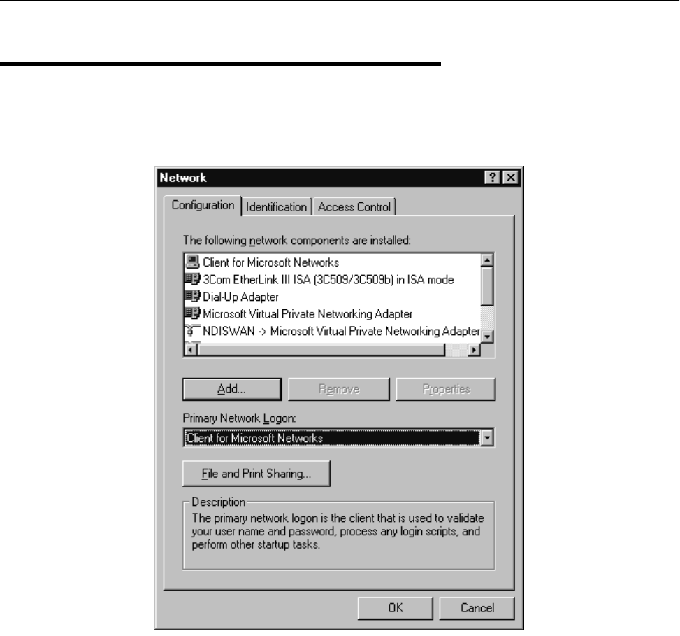
Appendix C: Configuring a Simple Data Network
128 AWE 120-58 Installation & Configuration Guide
Configuring the Network
To configure the network
1. In the Control Panel window, double-click the Network icon. The Network window is displayed.
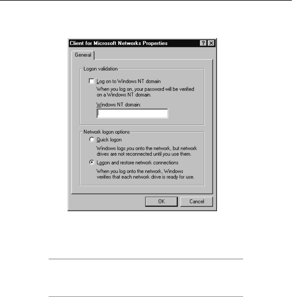
Configuring the Network
APR 2001 Rev 03 129
2. In the list of network components area, double-click Client for Microsoft Networks. The Client for
Microsoft Networks Properties window is displayed.
Note: If Client for Microsoft Networks is not listed, click Add and select Client, Add, Microsoft, Client
for Microsoft Networks, and then click OK.
3. In the Client for Microsoft Networks Properties window, do the following tasks.
4. Click OK. The Client for Microsoft Networks Properties window closes.
Log on to Windows NT domain Clear the checkbox
Windows NT domain Clear the field
Logon and restore network connections Click the button
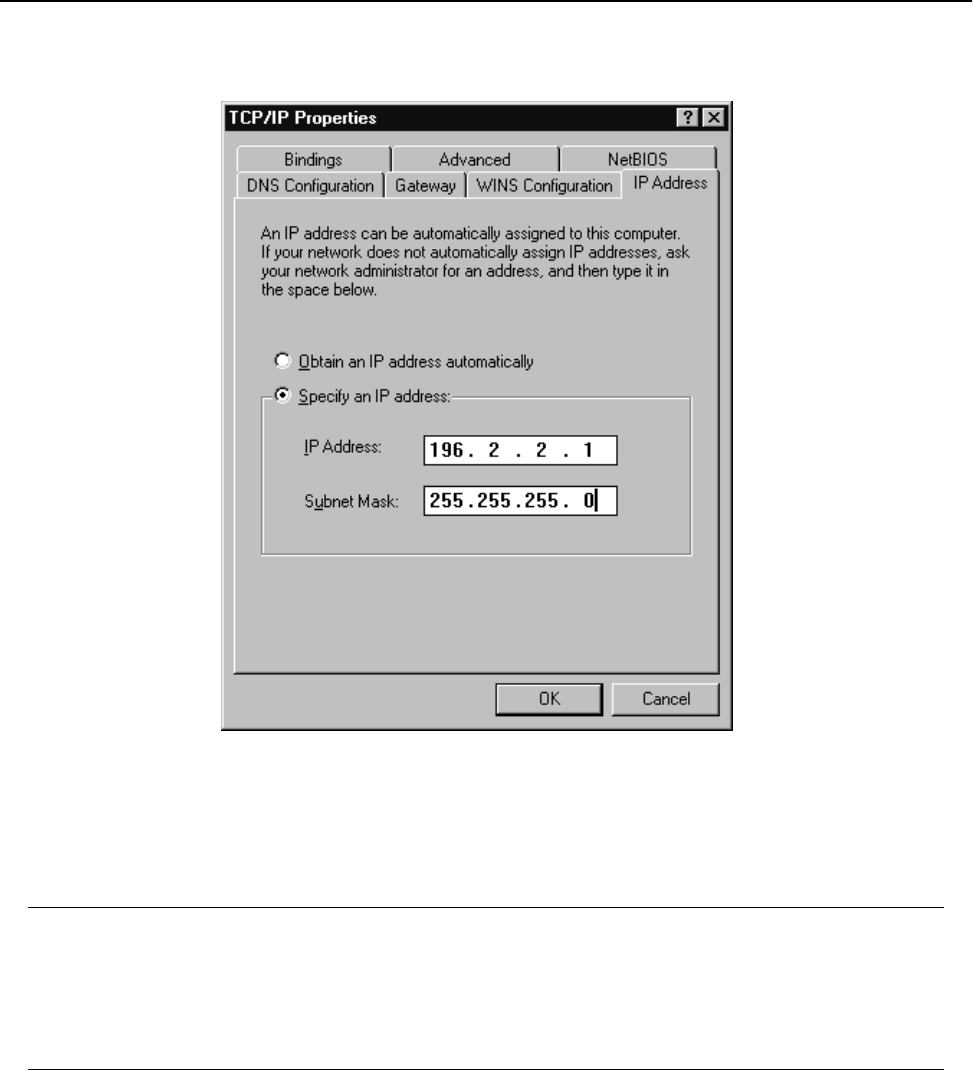
Appendix C: Configuring a Simple Data Network
130 AWE 120-58 Installation & Configuration Guide
5. In the Network window, double-click TCP/IP. The TCP/IP Properties window is displayed.
Note: If TCP/IP is not listed in the Network window, click Add and select Protocol, Add, Microsoft, TCP/
IP, and then click OK.
6. Click the IP Address tab.
7. Click Specify an IP Address, and type the following.
8. Click OK.
9. Click File and Print Sharing. The File and Print Sharing window is displayed.
10. Click to select the I want to be able to give others access to my files checkbox.
11. Click OK.
IP Address 196.2.2.1
Note: Increment the last digit by 1 (i.e. type 196.2.2.2) when configuring
the second computer
Subnet Mask 255.255.255.0
Note: This number is the same for both computers
Enabling Sharing on the Hard Disk Drive
APR 2001 Rev 03 131
12. In the Network window, click the Identification tab and type the following.
13. In the Network window, click the Access Control tab.
14. Click Share Level Access Control.
15. Click OK.
16. You are prompted to restart your computer.
17. Click Ye s . Wait for your computer to restart, then proceed with Enabling the Sharing Feature on the
Hard Disk Drive.
Enabling Sharing on the Hard Disk Drive
To enable the sharing feature on the hard disk drive
1. On the desktop, double-click My Computer. The My Computer window is displayed.
Computer Name Unique name for each computer. For example, computer 1
and computer 2
Workgroup Workgroup name. For example, Test
Note: All computers in the network must have the same workgroup
name
Computer Description Description of the type of computer used. For example, laptop or
desktop
Appendix C: Configuring a Simple Data Network
132 AWE 120-58 Installation & Configuration Guide
2. Right-click the hard disk drive icon (typically drive C:), and select Open. The Properties window is
displayed.
3. Click the Sharing tab, and choose the following:
4. Click OK.
5. Repeat this procedure for all PCs in the network.
Once all PCs in the network have been shared, you can view the network by double clicking the Network
Neighborhood icon that appears on each PC desktop.
Shared As Click the radio button
Share Name Type C
Comment Leave this field blank
Access Type Click to select Full
Passwords Leave these fields blank

APR 2001 Rev 03 133
Appendix D: SNMP
About SNMP MIB
Three elements are required to use SNMP: agent software, management software and a MIB file. SNMP agent
software is contained in every AWE unit. Agent software enables a unit to interpret SNMP (Simple Network
Management Protocol) MIB (Management Information Block) commands.
SNMP management software is installed on a networked PC or workstation and enables a network
administrator to remotely manage AWE units. If you have SNMP manager software installed on a networked
PC or workstation, you can configure, monitor and control AWE units via the Ethernet or air. SNMP network
management software is available commercially and as shareware (for example, you can download a free
evaluation copy from www.mg-soft.com).
MIB is simply a list of objects that SNMP can monitor. You can download a proprietary Wi-LAN MIB file from
www.wi-lan.com or obtain a copy through the Wi-LAN Technical Assistance Center. The AWE 120-58 is MIB
version 2 compliant. After you download the MIB file, you must compile the file with the SNMP management
software compiler.
SNMP Elements
SNMP Element Description
Manager Software installed on the network’s host computer and
operated by the network administrator. From the host, the
Manager configures Agents or polls Agents for information
Agent Software that runs on each unit. An Agent accepts
configuration commands from the Manager and collects
network and terminal information specified in the MIB
Management Information Block (MIB) A database that is accessed by a specific set of commands
and executed using the SNMP manager. There is a standard
MIB and a Wi-LAN customized MIB that stores information
relevant to the operation of a wireless network

Appendix D: SNMP
134 AWE 120-58 Installation & Configuration Guide
Wi-LAN Object Identifier Nodes
The AWE 120-58 uses SNMP version 1, which is MIB 2 compliant. All OID (Object Identifier) nodes in the
AWE 120-58 private Wi-LAN MIB are numbered 1.3.6.1.4.1.2686.2.n where n is a private Wi-LAN MIB node
number or branch of nodes.
All nodes containing statistical information are cleared on power up and reset.
Values in all writeable nodes are stored in Flash memory and are retained until overwritten by the
administrator, even following power down or reset.
Using SNMP
Refer to the documentation provided with your SNMP application software for instructions about using
SNMP. The procedure for changing a unit’s configuration with SNMP is described below.
To change a configuration setting with SNMP
1. Change the parameter to a new value using the appropriate SNMP command.
2. Reboot the unit with the new configuration using the rebootNewRfConfig node command. See System
Commands, page 147.
3. Save the new configuration to the unit’s flash memory using the saveConfToFlash node command. See
System Commands, page 147.
From To Classification
1.3.6.1.4.1.2686.2.1.1 1.3.6.1.4.1.2686.2.1.104 Configuration
1.3.6.1.4.1.2686.2.1.100.1 1.3.6.1.4.1.2686.2.1.100.7 Configuration:
System Image List
1.3.6.1.4.1.2686.2.2.1 1.3.6.1.4.1.2686.2.2.7 System Status
1.3.6.1.4.1.2686.2.3.1 1.3.6.1.4.1.2686.2.3.32 Statistics
1.3.6.1.4.1.2686.2.4.1 1.3.6.1.4.1.2686.2.4.7 System Commands

Using Object Identifier Nodes
APR 2001 Rev 03 135
Using Object Identifier Nodes
The following are descriptions of parameters and node addresses in the AWE 120-58 MIB.
Group Parameter Address/Node Syntax Access Description
Configuration serialNumber 1.3.6.1.4.1.2686.2.1.1 DisplayString
(0..15)
Read Only Unit Serial Number
productionDate 1.3.6.1.4.1.2686.2.1.2 DisplayString
(0..15)
Read Only Unit Date of Manufacture
macAddress 1.3.6.1.4.1.2686.2.1.3 PhysAddress Read Only Ethernet MAC Address
systemName 1.3.6.1.4.1.2686.2.1.4 DisplayString
(0..31)
Read/Write Unit System Name
unitLocation 1.3.6.1.4.1.2686.2.1.5 DisplayString
(0..31)
Read/Write User configurable Unit Location
contactName 1.3.6.1.4.1.2686.2.1.6 DisplayString
(0..31)
Read/Write User configurable Contact Name
config7 1.3.6.1.4.1.2686.2.1.7 INTEGER Read/Write Spare
config8 1.3.6.1.4.1.2686.2.1.8 INTEGER Read/Write Spare
config9 1.3.6.1.4.1.2686.2.1.9 INTEGER Read/Write Spare
ipAddress 1.3.6.1.4.1.2686.2.1.10 IpAddress Read Only Internet IP Address: default = 192.168.1.100
ipNewAddress 1.3.6.1.4.1.2686.2.1.11 IpAddress Read/Write New Internet IP Address
ipSubnetMask 1.3.6.1.4.1.2686.2.1.12 IpAddress Read/Write IP Subnet Mask: default = 255.255.255.0
ipGatewayAddr 1.3.6.1.4.1.2686.2.1.13 IpAddress Read/Write IP default gateway address (currently not used)
ipNetmanAddr 1.3.6.1.4.1.2686.2.1.14 IpAddress Read/Write SNMP network management station IP address
ipPacketFiltering 1.3.6.1.4.1.2686.2.1.15 INTEGER) Read/Write IP packet filtering:
0 = disabled, 1 = enabled

Appendix D: SNMP
136 AWE 120-58 Installation & Configuration Guide
ipAddressFiltering 1.3.6.1.4.1.2686.2.1.16 INTEGER Read/Write IP address filtering:
0 = disabled, 1 = enabled
ipFilter1Range 1.3.6.1.4.1.2686.2.1.17 INTEGER Read/Write IP address filter 1 range: (0-255)
ipFilter1Base 1.3.6.1.4.1.2686.2.1.18 IpAddress Read/Write IP filter 1 base address
ipFilter2Range 1.3.6.1.4.1.2686.2.1.19 INTEGER Read/Write IP address filter 2 range: (0-255)
ipFilter2Base 1.3.6.1.4.1.2686.2.1.20 IpAddress Read/Write IP filter 2 base address
ipFilter3Range 1.3.6.1.4.1.2686.2.1.21 INTEGER Read/Write IP address filter 3 range: (0-255)
ipFilter3Base 1.3.6.1.4.1.2686.2.1.22 IpAddress Read/Write IP filter 3 base address
ipFilter4Range 1.3.6.1.4.1.2686.2.1.23 INTEGER Read/Write IP address filter 4 range: (0-255)
ipFilter4Base 1.3.6.1.4.1.2686.2.1.24 IpAddress Read/Write IP filter 4 base address
ipFilter5Range 1.3.6.1.4.1.2686.2.1.25 INTEGER Read/Write IP address filter 5 range: (0-255)
ipFilter5Base 1.3.6.1.4.1.2686.2.1.26 IpAddress Read/Write IP filter 5 base address
config27 1.3.6.1.4.1.2686.2.1.27 INTEGER Read/Write Spare
config28 1.3.6.1.4.1.2686.2.1.28 INTEGER Read/Write Spare
config29 1.3.6.1.4.1.2686.2.1.29 INTEGER Read/Write Spare
stationType 1.3.6.1.4.1.2686.2.1.30 INTEGER Read Only Current station type: 0 = remote, 1 = base
stationRank 1.3.6.1.4.1.2686.2.1.31 INTEGER Read Only Current station RF rank: 1 to 1000
Group Parameter Address/Node Syntax Access Description

Using Object Identifier Nodes
APR 2001 Rev 03 137
Group Parameter Address/Node Syntax Access Description
centerFreq 1.3.6.1.4.1.2686.2.1.32 INTEGER Read Only Current RF center frequency
(57410 to 58338)
securityWord1 1.3.6.1.4.1.2686.2.1.33 INTEGER Read Only Current RF security password 1
securityWord2 1.3.6.1.4.1.2686.2.1.34 INTEGER Read Only Current RF security password 2
securityWord3 1.3.6.1.4.1.2686.2.1.35 INTEGER Read Only Current RF security password 3
securityWord4 1.3.6.1.4.1.2686.2.1.36 INTEGER Read Only Current RF security password 4
securityWord5 1.3.6.1.4.1.2686.2.1.37 INTEGER Read Only Current RF security password 5
scramblingCode 1.3.6.1.4.1.2686.2.1.38 INTEGER Read Only Current RF scrambling code word
acquisitionCode 1.3.6.1.4.1.2686.2.1.39 INTEGER Read Only Current RF acquisition code (0-15)
configMinutes 1.3.6.1.4.1.2686.2.1.40 INTEGER Read Only Current RF configuration test minutes
(1-120)
repeaterMode 1.3.6.1.4.1.2686.2.1.41 INTEGER Read Only Current base station repeater mode:
0 = disabled, 1 = enabled
systemType 1.3.6.1.4.1.2686.2.1.42 INTEGER Read Only Current base station symmetry:
0 = asymmetric, 1 = symmetric
remoteGroup 1.3.6.1.4.1.2686.2.1.43 INTEGER Read Only Current RF group identifier:
0 = closed, 1 - 63 = special group
numOfPollRounds 1.3.6.1.4.1.2686.2.1.44 INTEGER Read Only Current Number of Polling Rounds (1-60)

Appendix D: SNMP
138 AWE 120-58 Installation & Configuration Guide
txPwrLevelAdj 1.3.6.1.4.1.2686.2.1.45 INTEGER Read Only Current RF Tx Power Level Adjust (-31 to 0 dB)
defStationType 1.3.6.1.4.1.2686.2.1.46 INTEGER Read Only Default Station type: 0 = remote, 1 = base
defStationRank 1.3.6.1.4.1.2686.2.1.47 INTEGER Read Only Default Station RF Rank
Group Parameter Address/Node Syntax Access Description
Integer
Value
Atten.
(dB)
Integer
Value
Atten.
(dB)
Integer
Value
Atten.
(dB)
0311120229
1301219238
2291318247
3281417256
4271516265
5261615274
6251714283
7241813292
8231912301
9222011310
10 21 21 10

Using Object Identifier Nodes
APR 2001 Rev 03 139
Group Parameter Address/Node Syntax Access Description
defCenterFreq 1.3.6.1.4.1.2686.2.1.48 INTEGER Read Only FLASH RF center frequency
(57410 to 58338)
defSecurityWord1 1.3.6.1.4.1.2686.2.1.49 INTEGER Read Only Default RF security password 1
defSecurityWord2 1.3.6.1.4.1.2686.2.1.50 INTEGER Read Only Default RF security password 2
defSecurityWord3 1.3.6.1.4.1.2686.2.1.51 INTEGER Read Only Default RF security password 3
defSecurityWord4 1.3.6.1.4.1.2686.2.1.52 INTEGER Read Only Default RF security password 4
defSecurityWord5 1.3.6.1.4.1.2686.2.1.53 INTEGER Read Only Default RF security password 5
defScramblingCode 1.3.6.1.4.1.2686.2.1.54 INTEGER Read Only Default RF scrambling code word
defAcquisitionCode 1.3.6.1.4.1.2686.2.1.55 INTEGER Read Only Default RF acquisition code (0-15)
defConfigMinutes 1.3.6.1.4.1.2686.2.1.56 INTEGER Read Only Default RF configuration test minutes (1-120)
deRepeaterMode 1.3.6.1.4.1.2686.2.1.57 INTEGER Read Only Default base station repeater mode:
0 = disabled, 1 = enabled
defSystemType 1.3.6.1.4.1.2686.2.1.58 INTEGER Read Only Default base station symmetry type:
0 = asymmetric, 1 = symmetric
defRemoteGroup 1.3.6.1.4.1.2686.2.1.59 INTEGER Read Only Default RF group identifier:
0 = closed, 1 - 63 = special group
defNumOfPollRounds 1.3.6.1.4.1.2686.2.1.60 INTEGER Read Only Default Number of Polling Rounds (1-60)

Appendix D: SNMP
140 AWE 120-58 Installation & Configuration Guide
defTxPwrLevelAdj 1.3.6.1.4.1.2686.2.1.61 INTEGER Read Only Default RF Tx Power Level Adjust (-31 to 0 dB)
newStationType 1.3.6.1.4.1.2686.2.1.62 INTEGER Read/Write New station type: 0 = remote, 1 = base
newStationRank 1.3.6.1.4.1.2686.2.1.63 INTEGER Read/Write New station RF rank (1-1000)
Group Parameter Address/Node Syntax Access Description
Integer
Value
Atten.
(dB)
Integer
Value
Atten.
(dB)
Integer
Value
Atten.
(dB)
0311120229
1301219238
2291318247
3281417256
4271516265
5261615274
6251714283
7241813292
8231912301
9222011310
10 21 21 10

Using Object Identifier Nodes
APR 2001 Rev 03 141
Group Parameter Address/Node Syntax Access Description
newCenterFreq 1.3.6.1.4.1.2686.2.1.64 INTEGER Read/Write New RF center frequency
(57410 to 58338)
newSecurityWord1 1.3.6.1.4.1.2686.2.1.65 INTEGER Read/Write New RF security password 1
newSecurityWord2 1.3.6.1.4.1.2686.2.1.66 INTEGER Read/Write New RF security password 2
newSecurityWord3 1.3.6.1.4.1.2686.2.1.67 INTEGER Read/Write New RF security password 3
newSecurityWord4 1.3.6.1.4.1.2686.2.1.68 INTEGER Read/Write New RF security password 4
newSecurityWord5 1.3.6.1.4.1.2686.2.1.69 INTEGER Read/Write New RF security password 5
newScramblingCode 1.3.6.1.4.1.2686.2.1.70 INTEGER Read/Write New RF scrambling code word
newAcquisitionCode 1.3.6.1.4.1.2686.2.1.71 INTEGER Read/Write New RF acquisition code (0-15)
newConfigMinutes 1.3.6.1.4.1.2686.2.1.72 INTEGER Read/Write New RF configuration test minutes (1-120)
newRepeaterMode 1.3.6.1.4.1.2686.2.1.73 INTEGER Read/Write New base station repeater mode:
0 = disabled, 1 = enabled
newSystemType 1.3.6.1.4.1.2686.2.1.74 INTEGER Read/Write New base station symmetry type:
0 = asymmetric, 1 = symmetric
newRemoteGroup 1.3.6.1.4.1.2686.2.1.75 INTEGER Read/Write New RF group identifier:
0 = closed, 1 - 63 = special group
newNumOfPollRounds 1.3.6.1.4.1.2686.2.1.76 INTEGER Read/Write New Number of Polling Rounds (1-60)

Appendix D: SNMP
142 AWE 120-58 Installation & Configuration Guide
newTxPwrLevelAdj 1.3.6.1.4.1.2686.2.1.77 INTEGER Read/Write New RF Tx Power Level Adjust (-31 to 0 dB)
stationMode 1.3.6.1.4.1.2686.2.1.78 INTEGER Read/Write Operating mode:
0 = normal, 1 = Rx Test,
2 = Tx Test, 3 = RSSI Test
rfTransmitStatus 1.3.6.1.4.1.2686.2.1.79 INTEGER Read/Write RF transmit status:
0 = blocked, 1 = unblocked
linkMonitorPeriod 1.3.6.1.4.1.2686.2.1.80 INTEGER Read/Write Link monitor period (0-10000):
0 = disabled, 1 - 10,000 = number of data
superframes per single test superframe
testModeTimer 1.3.6.1.4.1.2686.2.1.81 INTEGER Read/Write Test mode timer minutes (1-1000)
Group Parameter Address/Node Syntax Access Description
Integer
Value
Atten.
(dB)
Integer
Value
Atten.
(dB)
Integer
Value
Atten.
(dB)
0311120229
1301219238
2291318247
3281417256
4271516265
5261615274
6251714283
7241813292
8231912301
9222011310
10 21 21 10

Using Object Identifier Nodes
APR 2001 Rev 03 143
remoteDistance 1.3.6.1.4.1.2686.2.1.82 INTEGER Read/Write Maximum remote unit distance (km)
linkMonitorRank 1.3.6.1.4.1.2686.2.1.83 INTEGER Read/Write Link monitor remote station rank (1-1000)
throttleEnable 1.3.6.1.4.1.2686.2.1.84 INTEGER Read/Write Throttling enable:
0 = disabled, 1 = enabled
throttleLevel 1.3.6.1.4.1.2686.2.1.85 INTEGER Read/Write RF throttle level (1-50)
config86 1.3.6.1.4.1.2686.2.1.86 INTEGER Read/Write Spare
config87 1.3.6.1.4.1.2686.2.1.87 INTEGER Read/Write Spare
config88 1.3.6.1.4.1.2686.2.1.88 INTEGER Read/Write Spare
config89 1.3.6.1.4.1.2686.2.1.89 INTEGER Read/Write Spare
communityName1 1.3.6.1.4.1.2686.2.1.90 DisplayString(0
..15)
Read/Write Read-only access community name
communityName2 1.3.6.1.4.1.2686.2.1.91 DisplayString(0
..15)
Read/Write Read-Write access community name
ethernetAccess 1.3.6.1.4.1.2686.2.1.92 INTEGER Read Only Ethernet access to local host:
0 = disabled, 1 = enabled
Group Parameter Address/Node Syntax Access Description
Integer Distance
(km) Integer Distance
(km)
15735
2108 40
3159 45
4201050
5251150
6301260

Appendix D: SNMP
144 AWE 120-58 Installation & Configuration Guide
wirelessAccess 1.3.6.1.4.1.2686.2.1.93 INTEGER Read Only Wireless access to local host:
0 = disabled, 1 = enabled
config94 1.3.6.1.4.1.2686.2.1.94 INTEGER Read/Write Spare
currentImage 1.3.6.1.4.1.2686.2.1.95 DisplayString(0
..15)
Read Only Current system image file name
defaultImage 1.3.6.1.4.1.2686.2.1.96 DisplayString(0
..15)
Read/Write Selects specified system image file as default
prevDefaultImage 1.3.6.1.4.1.2686.2.1.97 DisplayString(0
..15)
Read Only Previous default system image file name
config98 1.3.6.1.4.1.2686.2.1.98 INTEGER Read/Write Spare
config99 1.3.6.1.4.1.2686.2.1.99 INTEGER Read/Write Spare
System Image
List
systemImageList 1.3.6.1.4.1.2686.2.1.100 SEQUENCE
OF
SystemImageE
ntry
not
accessible
System Image List Branch
systemImageNumber 1.3.6.1.4.1.2686.2.1.100.1 INTEGER Read Only System image number
systemImageName 1.3.6.1.4.1.2686.2.1.100.2 DisplayString(0
..15)
Read Only System image file name
systemImageRevn 1.3.6.1.4.1.2686.2.1.100.3 DisplayString(0
..15)
Read Only System image revision identifier
systemImageDate 1.3.6.1.4.1.2686.2.1.100.4 DisplayString(0
..15)
Read Only System image file date
systemImageTime 1.3.6.1.4.1.2686.2.1.100.5 DisplayString(0
..15)
Read Only Time system image file was last changed
systemImageSize 1.3.6.1.4.1.2686.2.1.100.6 INTEGER Read Only System image file size
systemImageText 1.3.6.1.4.1.2686.2.1.100.7 DisplayString(0
..15)
Read Only System image descriptive text
Group Parameter Address/Node Syntax Access Description

Using Object Identifier Nodes
APR 2001 Rev 03 145
config101 1.3.6.1.4.1.2686.2.1.101 INTEGER Read/Write Spare
config102 1.3.6.1.4.1.2686.2.1.102 INTEGER Read/Write Spare
config103 1.3.6.1.4.1.2686.2.1.103 INTEGER Read/Write Spare
config104 1.3.6.1.4.1.2686.2.1.104 INTEGER Read/Write Spare
System Status totalHours 1.3.6.1.4.1.2686.2.2.1 Counter Read Only Cumulative run-time hours
systemHours 1.3.6.1.4.1.2686.2.2.2 Counter Read Only Current run-time hours since powerup
loginOkays 1.3.6.1.4.1.2686.2.2.3 Counter Read Only Number of successful logins
loginFails 1.3.6.1.4.1.2686.2.2.4 Counter Read Only Number of unsuccessful login attempts
localUser 1.3.6.1.4.1.2686.2.2.5 INTEGER Read Only Local user login status:
0 = none, 1 = user, 2 = supervisor
telnetUser 1.3.6.1.4.1.2686.2.2.6 INTEGER Read Only Telnet user login status:
0 = none, 1 = user, 2 = supervisor
ftpUser 1.3.6.1.4.1.2686.2.2.7 INTEGER Read Only FTP user login status:
0 = none, 1 = user, 2 = supervisor
Statistics etherRxTotalPkts 1.3.6.1.4.1.2686.2.3.1 Counter Read Only Total Ethernet packets received
etherRxLocalPkts 1.3.6.1.4.1.2686.2.3.2 Counter Read Only Ethernet packets received for local host
etherRxErrorPkts 1.3.6.1.4.1.2686.2.3.3 Counter Read Only Ethernet packets received in error
etherRxDroppedPkts 1.3.6.1.4.1.2686.2.3.4 Counter Read Only Number of received Ethernet packets dropped
etherRxDiscardPkts 1.3.6.1.4.1.2686.2.3.5 Counter Read Only Number of received Ethernet packets Discarded
etherRxTotalKbytes 1.3.6.1.4.1.2686.2.3.6 Counter Read Only Total Ethernet KBytes received since last reset
etherRxBcastKbytes 1.3.6.1.4.1.2686.2.3.7 Counter Read Only Ethernet KBytes received since last reset
etherTxBTotalPkts 1.3.6.1.4.1.2686.2.3.8 Counter Read Only Total Ethernet packets transmitted
etherTxDroppedPkts 1.3.6.1.4.1.2686.2.3.9 Counter Read Only Ethernet transmit packets dropped
Group Parameter Address/Node Syntax Access Description

Appendix D: SNMP
146 AWE 120-58 Installation & Configuration Guide
etherTxTotalKbytes 1.3.6.1.4.1.2686.2.3.10 Counter Read Only Total Ethernet KBytes transmitted since last reset
etherTxBcastKbytes 1.3.6.1.4.1.2686.2.3.11 Counter Read Only Ethernet broadcast KBytes transmitted since last
reset
rfRxTotalPkts 1.3.6.1.4.1.2686.2.3.12 Counter Read Only Total received RF packets
rfRxLocalPkts 1.3.6.1.4.1.2686.2.3.13 Counter Read Only Total received RF packets for local host
rfRxDroppedPkts 1.3.6.1.4.1.2686.2.3.14 Counter Read Only Number of received RF packets dropped
rfRxDiscardedPkts 1.3.6.1.4.1.2686.2.3.15 Counter Read Only Number of received RF packets discarded
rfTxTotalPkts 1.3.6.1.4.1.2686.2.3.16 Counter Read Only Total transmitted RF packets
rfTxLocalPkts 1.3.6.1.4.1.2686.2.3.17 Counter Read Only Number of transmitted local RF packets
rfTxDroppedPkts 1.3.6.1.4.1.2686.2.3.18 Counter Read Only Number of transmitted RF packets dropped
rfRxSframeCount 1.3.6.1.4.1.2686.2.3.19 Counter Read Only Total RF super frames received
rfRxOverrunErrors 1.3.6.1.4.1.2686.2.3.20 Counter Read Only Number of RF overrun errors
rfRxSFrameErrors 1.3.6.1.4.1.2686.2.3.21 Counter Read Only Number of RF super frame control word errors
rfRxChecksumErrors 1.3.6.1.4.1.2686.2.3.22 Counter Read Only Number of RF super frame header checksum
errors
rfRxPacketErrors 1.3.6.1.4.1.2686.2.3.23 Counter Read Only Number of RF packet control work errors
rfRxLengthErrors 1.3.6.1.4.1.2686.2.3.24 Counter Read Only Number of RF super frame length errors
rfTxSuperFrameCnt 1.3.6.1.4.1.2686.2.3.25 Counter Read Only Number of RF super frames transmitted
rfEtoIThroughput 1.3.6.1.4.1.2686.2.3.26 Counter Read Only Ethernet to RF throughput
rfItoEThroughput 1.3.6.1.4.1.2686.2.3.27 Counter Read Only RF to Ethernet throughput
statistics24 1.3.6.1.4.1.2686.2.3.28 Counter Spare
linkMonitorRank1 1.3.6.1.4.1.2686.2.3.29 INTEGER Read Only Link monitor remote station rank
linkMonRtoBber 1.3.6.1.4.1.2686.2.3.30 DisplayString
(0..8)
Read Only Link monitor remote to base bit error rate
Group Parameter Address/Node Syntax Access Description

Using Object Identifier Nodes
APR 2001 Rev 03 147
linkMonBtoRber 1.3.6.1.4.1.2686.2.3.31 DisplayString
(0..8)
Read Only Link monitor base to remote bit error rate
linkMonMissPktCnt 1.3.6.1.4.1.2686.2.3.32 Counter Read Only Link monitor missed packet count
linMonEnvPBtoR 1.3.6.1.4.1.2686.2.3.33 INTEGER Read Only Link monitor base to remote envelope power
linkMonEnvPRtoB 1.3.6.1.4.1.2686.2.3.34 INTEGER Read Only Link monitor remote to base envelope power
linkMonCorrPBtoR 1.3.6.1.4.1.2686.2.3.35 INTEGER Read Only Link monitor base to remote correlation power
linkMonCorrPRtoB 1.3.6.1.4.1.2686.2.3.36 INTEGER Read Only Link monitor remote to base correlation power
System
Commands
rebootCurrent 1.3.6.1.4.1.2686.2.4.1 INTEGER Read/Write Reboot current system image:
1 = reboot
rebootImage 1.3.6.1.4.1.2686.2.4.2 DisplayString
(0..15)
Read/Write Reboot specified system image:
system image file name
rebootNewRfConfig 1.3.6.1.4.1.2686.2.4.3 INTEGER Read/Write Reboot new RF configuration:
1 = reboot
restFactConfReboot 1.3.6.1.4.1.2686.2.4.4 INTEGER Read/Write Restore factory configuration and reboot:
1 = restore
saveConfToFlash 1.3.6.1.4.1.2686.2.4.5 INTEGER Read/Write Save current configuration to flash:
1 = save
resetRadioStats 1.3.6.1.4.1.2686.2.4.6 INTEGER Read/Write Reset radio statistics:
1 = reset
resetEthernetStats 1.3.6.1.4.1.2686.2.4.7 INTEGER Read/Write Reset Ethernet statistics:
1 = reset
Group Parameter Address/Node Syntax Access Description

Appendix D: SNMP
148 AWE 120-58 Installation & Configuration Guide

APR 2001 Rev 03 149
Appendix E: Technical Reference Information
Front Panel LEDs
.
Note: The Air LED and the Wire LED are bi-color LEDs: red and green. The displayed color depends on the
proportion of received data to transmitted data. The LEDs are mostly green when more data is
received than transmitted, and mostly red when more data is transmitted than received. When
approximately equal amounts of data are received and transmitted at the same time, the LEDs is
orange, which is the color that results from combining equal amounts of red and green.
LED Type Color Status
Air (in Normal
Mode)
Orange Transmitting and receiving approximately equal
amounts of data over the air
Green Receiving data from the air
Red Transmitting data to the air
Off Listening to the air
Mode Green Receive test mode - RS-232 displays statistics
Red Continuous Transmit test mode
Orange RSSI test mode - measures fade margin, which is
indicated by the color of the Air LED
Off Normal transceiver mode
Wire Green Receiving data from the wire
Red Transmitting data to the wire
Orange Transmitting and receiving data on the wire
Off Listening to the wire or no wire connnected
Power Green Power is connected to the transceiver
Off No power is connected to the transceiver
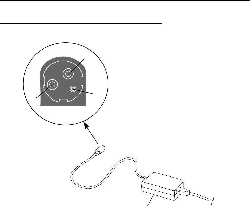
Appendix E: Technical Reference Information
150 AWE 120-58 Installation & Configuration Guide
DC Power Plug Pinout
Pin 1 +12 VDC
Pin 2 GND
Pin 3 N/C
DC Power Plug
2
1
3
Power Supply Unit AC Power Cord
Detail
APR 2001 Rev 03 151
Wi-LAN AWE 120-58 Main Menu
Unit Identification
Hardware/Software Revision
System Software ROM Images
Current System Status
Network Configuration
IP Filter Configuration
RF Station Configuration
Radio Module Configuration
RF/Ethernet Statistics
System Security
System Commands
Link Monitor Display
Logout
Unit Identification
Serial Number
Production Date
Ethernet MAC Address
Unit Name/Description
Unit Location
Contact Name
System Revision Information
Hardware
ROM Size
RAM Size
Software
File Name
System Software ROM Images
System Current Status
Cumulative Run-Time
Current Run-Time
Successful Logins
Unsuccessful Logins
Local User Logged In
Telnet User Logged In
FTP User Logged In
Network Configuration
Internet IP Address
New IP Address (Reboot Reqd)
Internet IP Subnet Mask
Default Gateway IP Address
SNMP NMS Trap IP Address
MAC Filter Entry Age Time Minutes
IP Filter Configuration
IP Packet Filtering
IP Address Filtering
Filter 1 Range
Filter 1 Base Address
Filter 2 Range
Filter 2 Base Address
Filter 3 Range
Filter 3 Base Address
Filter 4 Range
Filter 4 Base Address
Filter 5 Range
Filter 5 Base Address
RF Station Configuration
Operating Mode
RF Transmit Status
Link Monitor Period
Test Mode Timer Minutes
Base Station Only Parameters
Maximum Remote Distance
Link Monitor Remote Station Rank
Remote Station Only Parameters
Throttle Enable
Throttle Level
(view only)
System Security
SNMP Community Name 1
SNMP Community Name 2
Change User Password
Confirm User Password
Change Supervisor Password
Confirm Supervisor Password
Ethernet Access to Local Host
Wireless Access to Local Host
Auto Logout Minutes
System Commands
Default System Image
Reboot a System Image
Reboot Current Image
Restore Factory Config and Reboot
Reset Radio Statistics
Reset Ethernet Statistics
RF Link Monitor Statistics
RF Ethernet Statistics
(view only)
Appendix F: Menu Map
(view only)
Radio Module Configuration
Station Type
Station Rank
Center Frequency
Security Password 1
Security Password 2
Security Password 3
Security Password 4
Security Password 5
Scrambling Code
Acquisition Code
Config Test Minutes
Base Station Only Parameters
Repeater Mode
System Symmetry Type
Dynamic Polling Level
Remote Station Only Parameters
Remote Unit RF Group
Reboot New RF configuration
Save Current Config to Flash
Tx Power Level Adjust

Appendix F: Menu Map
152 AWE 120-58 Installation & Configuration Guide

APR 2001 Rev 03 153
Appendix G: Upgrading Software
If necessary, you can upgrade the software of a AWE 120-58. This section explains how to use FTP to
download a new software image to a AWE unit.
Before you can download a new software image you need the following items.
• A copy of the software image file
• A PC connected to the AWE unit via the network
• Basic network software installed on your PC, including ftp, ping, telnet, SNMP manager (optional)
Obtaining New Software Images
New software image files are available from the Wi-LAN support web page at www.wilan.com.
Downloading Image Software
1. Obtain the new image files.
2. Open a DOS session on your PC. From Windows®, choose Start, Programs, MS-DOS Prompt.
3. Copy the new image files to a known directory, for example c:\wilan\images. (Create a new
directory if a suitable directory does not already exist.)
4. Go to the directory by typing cd c:\wilan\images and press Enter.
5. List the contents of the directory. Type dir and press Enter. The names of image files should be listed in
the directory.
C:> copy <image filename> c:\wilan\images
This directory is an example only.

Appendix G: Upgrading Software
154 AWE 120-58 Installation & Configuration Guide
6. Type ftp <IP address> and press Enter where the IP address is the address of the AWE unit. The
PC connects to the unit.
Note: ftp must be installed on your PC.
7. Type "awe" and press Enter. The password prompt appears.
8. Type the supervisor password for the unit and press Enter. (Supervisor access is required to change unit
settings–see Setting Menu Passwords, page 92). The ftp> prompt appears.
9. After the ftp prompt, type the following "put" command.
Note: Leave a single space after "put."
where
.Current directory that contains the image file (for example,
c:\wilan\images)
<image filename> Name of the image file
c:\wilan\images>ftp 192.168.3.85
Connected to 192.168.3.85
220 Wi-LAN AWE 120-58 Ethernet Bridge FTP Server
User (192.168.3.85(none)):
This IP address is an example only.
Enter the IP address of your unit.
c:\wilan\images>ftp 192.168.3.85
Connected to 192.168.3.85
220 Wi-LAN AWE 120-58 Ethernet Bridge FTP Server
User (192.168.3.85(none)):awe
331 Password required
Password:
ftp> put .\<image filename>

Activating New Software Images
APR 2001 Rev 03 155
10. Press Enter. The image file transfers from the PC to the unit. The status of the transfer, the file size and
the transfer time are displayed.
Tip: If you type ftp> help, online instructions for using ftp are displayed.
11. Type bye and press Enter to exit ftp and return to the DOS window.
12. Activate the new software image. See Activating New Software Images, below.
Activating New Software Images
After you download new image files to a unit, you need to configure the unit to operate from the new image
rather than from the current image. If you are on-site, you can use the Main Menu to select the default image.
See Setting Default System Image, page 97.
If you are at a remote location from the unit, you can use telnet to access the unit’s configuration menu or
use SNMP manager software (SNMP parameter = defaultImage) to choose the default image file. See Appendix
D: SNMP, page 133.
Removing Old Software Images
To delete old software images from a AWE unit, you must use ftp to connect to the unit, log in as a
"supervisor" and delete images using the "ftp delete" command. Images The amount of flash memory available
to store images is limited. To see the amount of memory available, see Viewing System Revision Information, page
39.
ftp>put .\<image filename>
200 Port set okay
150 Opening binary mode connection
226 Transfer complete
10484 bytes sent in 0.11 seconds (95.31 Kbytes/sec)
ftp>bye

Appendix G: Upgrading Software
156 AWE 120-58 Installation & Configuration Guide

APR 2001 Rev 03 157
Glossary
A
absorption
Antennas mounted too close to “soft” objects, such as trees, may experience a reduction
in signal strength due to absorption. Absorption is most often encountered in
applications installed during the fall or winter months. The problem does not become
evident until the spring when leaves appear.
acquisition code
To minimize the effects of interference, all units in a system use the same acquisition
code so the receivers can distinguish the desired signal from other interfering signals.
agent
In an SNMP context, the agent runs on each unit. An agent accepts configuration
commands from the manager and collects network and terminal information specified in
the MIB.
antenna
A device which accepts electromagnetic energy from a circuit or wire and radiates it into
space rather than confining it.
antenna gain
Gain of the antenna over a dipole (dBd) or isotropic (dBi).
• Antennas have a gain associated with them, which is a measure of their ability to
amplify signals in their tuned band.
• Antenna gain is achieved by focusing the signal. A higher gain antenna has more
compressed signal.
ARP
Address Resolution Protocol. A low-level protocol that maps IP addresses to Ethernet
addresses. An ARP request is sent out to the network along with an IP address. The node
with the address responds to the request with a hardware address so the transmission
can take place.
attenuation
Any loss in signal strength, due to resistance, absorption, capacitance or any
characteristic of the medium or design of the system.

Glossary
158 AWE 120-58 Installation & Configuration Guide
B
base station
The central control unit of the wireless network. A base station polls remote units and
controls how traffic is routed to remotes. The base usually connects to a major access
point of main wired network.
beamwidth
The beamwidth of an antenna describes how a signal spreads out from the antenna as
well as the range of the reception area. Beamwidth is measured between the points on
the beam pattern at which the power density is half of the maximum power. This is often
referred to as the -3 dB points. A high gain antenna has a very narrow beamwidth and
may be more difficult to align.
BER
Bit Error Rate. A percentage of bits per million, showing the number of bits in error
compared to the data bits actually sent.
blocking
Blocking is an operating mode where the radio receives only. Unblocked is the normal
operating mode.
C
cable loss
The signal loss experienced as it passes through the coax cable. Expressed in dB.
channel
The part of the spectrum band occupied by a radio signal, usually measured in
kilohertz (kHz).
closed system
A system where remotes cannot communicate directly with each other. They can only
communicate with each other via a base station.
coaxial cable
A type of wire where the inner conductor is surrounded by an outer conductor. The
outer conductor serves as an electrical shield.
co-location
Refers to placing base stations or units in the same location. In this situation, base
stations or units can interfer with each other unless steps are taken to isolate the
systems from one another (such as aligning antennas or using different channels).
collision
The situation that exists when two users try to send a signal over the same medium at
the same time and the signal uses the same frequencies.
configuration menus
Menus that allow the viewing and setting of unit parameters.

APR 2001 Rev 03 159
contentionless polling
A form of dynamic polling that ignores idle remote stations. The number of polls that an
idle remote is ignored can be set to maximize polling to active stations.
Cross-Polarization Discrimination
See XPD.
D
dB
Decibel. A relative measure of power used to specify power gains and losses. The
difference in power P1 and P2 expressed in dB is
DB9
A D-shaped connector with 9 pins.
dBd
dBd is antenna gain referenced over a half-wave dipole which is an antenna that has a
donut shaped radiation pattern. Gain of a Standard Dipole = 2.14 dBi.
dBi
dBi is antenna gain referenced over an isotropic radiator which is a theoretical antenna
that radiates equally in all directions (e.g. the sun). Wi-LAN references antenna gain in
dBi. The conversion factor is: 0 dBd = 2.14 dBi.
dBm
A power measurement referenced to one milliwatt. This is an absolute measure of gain.
diffraction
Diffraction occurs when a radio signal reflects or bounces off of a solid object. The level
of diffraction could lead to connectivity problems if the remaining signal level is too low.
Two types of diffraction are shadowing and multipath.
downtilt
Some antennas have either an associated downtilt or an uptilt. The tilt further focuses the
signal either downward or upward with respect to the horizon. A tilt may be either
electrically built into the antenna or achieved mechanically with the mounting gear. An
downtilt or uptilt may be required when there is a significant deviation between the
elevation of the remote site(s) and the base site.
DSSS
Direct sequence spread spectrum. A method of expanding the radio signal over a broad
portion of the radio band.
dynamic polling (DP)
A polling protocol in which idle units are not polled as frequently as active units. Since
less time is spent polling idle remotes, there are more available resources for active units
and overhead is reduced.
dB 10 P1P2⁄()log×=

Glossary
160 AWE 120-58 Installation & Configuration Guide
dynamic time allocation (DTA)
A process for determining how active a remote unit is. A unit is allowed a brief time to
respond to a poll before the remote is considered idle.
E
EEPROM
Electrically Erasable, Programable Read Only Memory: non-volatile memory.
EIRP
Effective Isotropically Radiated Power. EIRP is the amount of power that is transmitted to
the air from the antenna. EIRP levels depend on the power of the radio transmitter, the
size of the antenna and the losses incurred in the antenna cable. To remain license
exempt, the EIRP must remain under 4 watts or 36 dBm in Canada and the United States
for point-to-multipoint applications. In Europe, this value is reduced to 100 mW or to
20 dBm.
Note: EIRP = Power out of unit – Power lost in cable + Gain in power from antenna
ERP
Effective Radiated Power. The power radiating from an antenna, taking into account the
output power from the transmitter, connector losses, cable losses and the antenna gain.
ETSI
European Telecommunications Standards Institute.
F
fade margin
The amount that the system gain plus the total antenna gain exceeds the path loss is
called the fade margin. The fade margin is calculated as the number of dB that the
received signal strength exceeds the minimum receiver sensitivity.
filtering
Filtering limits certain data packets or IP addresses from being passed by a unit.
FHSS
Frequency hopping spread spectrum. A method of spreading a narrowband signal across a
wide radio band by "hopping" the signal as a function of time.
Flash memory
A type of electrically erasable non-volatile memory that can easily be erased without
removal from a unit.
fresnel zone
The zone around the line of sight between two antennas. It consists of one of a
(theoretically infinite) number of a concentric ellipsoids of revolution that define volumes
in the radiation pattern of a (usually) circular aperture.

APR 2001 Rev 03 161
front to back ratio (F/B)
Directional antennas focus the signal in a forward path. This is achieved by directing the
signal in one direction that reduces the signal in the opposite direction. A higher gain
antenna typically has a greater F/B ratio.
ftp
File transfer protocol. A network utility program for moving files between nodes.
G
gain
The ability of a device to amplify a signal. Gain is the ratio of output power divided by
input power, usually expressed in decibels (dB). Gain can also be measured as an absolute
value, referenced to an input signal of 1 mW (dBm). For antennas, gain measures the
ability of an antenna to focus a signal and is expressed in dBd (half-wave dipole reference)
or dBi (isotrophic raditator reference).
gateway
The access point between one LAN and another LAN that would otherwise be
incompatible with each other. It is usually a hardware device that steers communication
between networks while performing code and protocol conversions.
I
IEEE
Institute of Electrical and Electronics Engineers.
image
An image is a collection of configurations or settings for a particular device. With the
unit, the System Image File contains a collection of configurations that are used when the
unit is rebooted.
interference
Any signal that tends to hamper the normal reception of a desired signal. Equivalent to
jamming except considered non-hostile in origin.
IP Address
A number assigned to a network node, domain or subdivision. The number consists of
four numbers—the first two numbers identify the network and subnetwork and the last
two numbers identify unique nodes in the network.
ISM
Industrial, Scientific, and Medical. It consists of three license-exempt radio bands in
North America and some European countries. It is also referred to as part 15.247 in the
FCC regulation that defines the parameters for use of the ISM band in the U.S., including
power outputs, spread-spectrum, and noninterference.

Glossary
162 AWE 120-58 Installation & Configuration Guide
L
link monitor
A AWE utility that sends known data over an active system to test the reliability of the RF
link. The link monitor information is overhead, that is, it reduces the amount of available
payload for message data.
LOS (Line of Sight)
A clear, visual line of sight between antennas. When standing at the antenna position, you
must be able to see the remote antenna. An elliptical pattern around the line of site,
known as the Fresnel Zone, must be kept free of obstructions
M
MAC address
Media Access Control address. Alphanumeric characters that uniquely identify a
network-connected device. To prevent unneccesary traffic over a radio channel, units
automatically learn the MAC addresses of equipment connected to the local Ethernet
segment and do not transmit over the radio channel if the destination is local. A packet
entering a subscriber unit from the radio port is not sent to the Ethernet port unless the
destination MAC address has been learned from packets entering the Ethernet port.
manager
When used in SNMP, this element is installed on the network’s host computer and is
controlled by the network administrator. From the host, the manager configures agents
or polls agents for information.
MIB
Management Information Block. The MIB is a database which is accessed by a specific set
of commands that you can execute using the SNMP Manager. There is a standard MIB and
a Wi-LAN customized MIB that stores information relevant to the operation of a
wireless network.
multipath interference
When a radio signal is transmitted, it can reflect off of physical objects in the
environment and take various paths to the receiver. As a result, the signal can arrive at a
receiver at different times, confuse the receiver, and cause bit errors and processing
delays.
O
OID nodes
Object Identifier Nodes. These are the individual nodes in a MIB. See SNMP and MIB.
open system
A system where remote units can communicate directly with each other and with the
base station.

APR 2001 Rev 03 163
overhead
Anything that reduces the payload capacity of a system is overhead, even if it serves a
useful function. The link monitor data is used to determine transmission statistics, but it
reduces the message carrying capacity of a wireless link and is considered overhead.
P
path loss
The total loss from one end of the path to the other. This includes propagation losses,
cable losses and any other losses that impact the system performance.
PN
Pseudo-random noise. A code used to change a narrowband signal into a spread
spectrum signal.
polarization
The orientation of the radiating element of an antenna with respect to earth. The
polarizaiton of antennas is usually described as being vertical, horizontal or circular.
point-to-multipoint
A wireless system where one base unit communicates with many remote units. The base
unit polls all the remotes and data passes between units to complete the network.
point-to-point
The simplest wireless system consisting of a base and one remote.
polling
The base unit in a AWE point-to-multipoint system handles multiple remotes by polling
each one sequentially. When a base polls a remote, data exchange between that remote
and the base takes place. The remote cannot exchange information with the base until it
is polled again.
propagation loss
The signal loss experienced as it travels through the air. Expressed in dB.
R
RF
Radio Frequency. A system of communication using electromagnetic waves propagated
through space. Because of varying characteristics, radio waves of different lengths are
used for different purposes and are usually identified by their frequency.
remote unit
A unit that can communicate with a base station or other remote units. A remote unit
forms a wireless link between a network segment and a base station.
repeater base
A repeater base rebroadcasts packets received from a remote unit to other remote
units. Remote units that cannot see each other (do not have LOS) can communicate
through a repeater base.

Glossary
164 AWE 120-58 Installation & Configuration Guide
RS-232
Standards for serial communications, which define the voltages, currents, data rates and
other factors about the signals to be used, as well as single-ended, differential, multi-drop
operation.
RSSI
Received Signal Strength Indicator. Strength of received signal expressed in dB. The AWE
unit measures RSSI as a fade margin value.
S
scrambling code
A code used to scramble messages, so that only units with the same scrambling can read
the messages.
sensitivity
The minimum signal strength required for usable performance by a unit. Expressed in
dBm.
shadowing
Shadowing is a form of diffraction that is typically caused when antennas are mounted
too close to a structure and lose a portion of the signal lobe due to reflection. The
receive antenna is in a shadowed area. To minimize shadowing, ensure that there is
adequate height above when mounting antenna equipment to a structure.
SNMP
Simple Network Management Protocol. A protocol you can use to remotely manage a
network element by polling, setting terminal values, and monitoring network statistics
and events. It is the de facto internet work management standard, designed to provide a
mechanism for the exchange of management information in a TCP/IP-based Internet
environment.
spread spectrum (SS)
Any of a group of modulation formats in which an RF bandwidth much wider than signal
bandwidth is used to transmit information, resulting in a greater immunity to noise
interference.
system gain
The maximum path loss that the system can support for usable data transmission.
system image file
The AWE unit uses system image files to store system configuration settings. The default
system image file is called “factory-image” and is used when the AWE is first powered up.
T
telnet
An Internet communications protocol that enables a computer to function as a terminal
working on a remote computer. A computer with a network connection to a AWE unit
can use telnet to access its configuration menus.

APR 2001 Rev 03 165
throttling
Throttling limits the amount of data that a remote station passes. This feature is used to
improve overall system performance by adjusting the throughput of a unit to match the
throughput of other devices in the network.
U
uptilt
See downtilt.
V
VSWR (Voltage Standing Wave Ratio)
VSWR is the voltage ratio of minimum to maximum across a transmission line. A VSWR
of 2.0:1 or less in an antenna is considered effective. Most antennas have a VSWR of 1.5:1.
For example, when using a radio with a 4 watt output with an antenna VSWR of 1.5:1, the
reflected power will be 160 milliwatts.
W
W-OFDM
Wide-band orthoganal frequency division multiplexing. A method patented by Wi-LAN
that divides a channel into several sub-channels, spreading the signal over the subchannels
and correcting errors without having to retransmit. W-OFDM permits several
independent channels to operate within the same band, enabling multipoint networks and
point-to-point systems to be overlaid in the same frequency band.
X
XPD (Cross-Polarization Discrimination)
Antennas have an associated polarity, which is the orientation of the radiating element
with respect to earth. Antennas are usually described as being vertically, horizontally or
circularly polarized. The polarity of all antennas used in a system must be the same. XPD
specifies the amount of signal isolation achieved when the receiving element is
perpendicular to the radiating element. This can be advantageous when co-locating radio
systems.

Glossary
166 AWE 120-58 Installation & Configuration Guide

APR 2001 Rev 03 167
Index
Numerics
10/100 BaseT connector 9
A
absorption
and antennas 119
defined 157
accessing
configuration menus 34–35
acquisition code 75
configuring 75
defined 157
adding to your network 30
address
SNMP NMS trap IP address 44
adjusting Tx power level 76
adminstrative best practices 105
agent
defined 157
agents
SNMP 133
antennas 118–122
absorption 119
beamwidth 118
clearance requirements 122
connector 9
cross-polarization discrimination 119
dBd vs. dBi 118
defined 157
diffraction 119
downtilt 118
EIRP 121
fade margin 121
fine-tuning 123
front to back ratio 118
gain 113, 115, 118, 157
installation factors 121
installing 122
list of approved 120
LOS 121
maximizing capabilities 121
minimal clearance 122
multipath interference 119
pre-installation 112
safety 121
selecting 120
shadowing 119
uptilt 118
voltage standing wave ratio 119
arrow keys
setting in telnet sessions 35
assembling units 14
asymmetric
base station system type 79
attenuation
and antennas 115
defined 157
auto logout minutes 95
automatic logout timeout 95
B
back panel 8
LED 9
base station
defined 158
pre-configuration steps 16
repeater mode 78
setting 68
system symmetry type
asymmetric 79
symmetric 79
basic RF link 21
testing 23
basic test setup 22
beamwidth
and antennas 118

Index
168 AWE 120-58 Installation & Configuration Guide
defined 158
bench test 21
bench test kit
contents 7
indoor antenna connection 14
part number 14
best practices 105
bit error rate
defined 158
display in link monitor 101
blocking
defined 158
C
cable loss
and link budget variables 114
defined 158
cabling 10
calculating
EIRP 114
Fresnel radius 116
propagation loss 115
center frequencies
configuring 72, 73
center frequency 72
choosing center frequencies 70
change user password 92, 93
changing configuration with SNMP 134
clearance requirements
antennas 122
closed system 81
coaxial cable 158
collision
defined 158
co-located base stations, installing 30
command line 104
command line interface 104
community names 91
setting 37
config test timeout period 67
configuration menus
accessing 34
navigating 34
configuration settings
restoring factory configuration 99
configuring
acquisition code 75
base station
maximum remote distance 62
repeater mode 78
system symmetry type 79
center frequencies 72, 73
community names 37
default gateway IP address 44
default system image file 97
Ethernet access 94
IP settings 44
network configuring 132
networks 128, 131
operating mode 51
passwords
login 92
radios 65–85
rank 69
remote access 94
remote station
RF group 83
throttling 64
scrambling code 74
SNMP NMS trap IP address 44
station type 68
test mode timer 53
timeout
login 95
unit
identification 37
name 38
configuring with the Main Menu 36
connecting antenna and power 15
connecting PC to management port 16
connectors
10/100 BaseT 9
antenna 9
power supply 9
contentionless polling 1
defined 159
copyright notice ix
Corr Power 101
correlation power 101
and the link monitor display 101
cross-polarization discrimination
and antennas 119
defined 165
cumulative run-time 41
current image
rebooting 98
current run-time 41
D
dB

APR 2001 Rev 03 169
defined 159
DB9 159
dBd
defined 159
vs. dBi 118
dBi
defined 159
default
IP gateway address 44
system image file 97
default image 97
descriptions of units
base station 2
remote unit 2
repeater 2
diffraction
and antennas 119
defined 159
distance
setting maximum remote distance 62
downtilt
antennas 118
defined 159
DSSS
defined 159
DTA 80
dual unit repeater 6
dyamic time allocation 80
dynamic polling
defined 159
dynamic polling level 80
dynamic time allocation
defined 160
E
EEPROM 160
EIRP
and link budget variables 113
antennas 121
calculating 114
defined 160
enabling
sharing on hard disk 132
throttling 64
Env Power 101
envelope power 101
and the link monitor display 101
equipment and tools 14
ERP 160
establishing a basic RF link 21
Ethernet
configuring access via 94
resetting statistics 100
viewing statistics 86
Ethernet statistics 86
ETSI 160
F
factory configuration 99
restoring 99
fade margins 160
and antennas 121
measuring with RSSI mode 59
fan
fan air vent 9
features 1
ferrite block
installing 25
FHSS
defined 160
field installation 29
filtering 160
filters
enabling IP address filtering 47
setting IP address filter range 48
setting IP filter base address 48
fine-tuning
antennas 123
Fresnel zone
defined 160
illustration 115
radius calculation 115
front panel 8
front to back ratio
and antennas 118
defined 161
ftp 30
upgrading software with 153
ftp user logged in 41
ftp, using 27
G
gain
defined 161
gateway
defined 161
gateway IP address
setting default 44
general equipment setup for RF tests 52
getting help x

Index
170 AWE 120-58 Installation & Configuration Guide
guidelines for field installation 29
H
hyperterminal
accessing menu with 34
starting 125
I
IEEE 161
image files
rebooting current 98
setting default 97
viewing 40
installation
block diagram 13
description of block diagram 13
overview 13
installation guidelines 29
installing
antennas 121, 122
weatherproofing 112
installing units in the field 29
interference
defined 161
multipath 119
internet IP
SNMP NMS trap address 44
internet IP address 43
IP address filtering 47
IP filters 45
IP packet filtering 47
IP subnet address
setting default 43
ISM 161
L
link budgets
antenna gain 113
cable loss 114
EIRP 113
path loss 114
propagation loss 113
system gain 113
variables 113
link monitor
configuring for remote station 64
performing link monitor test 54, 55
setting link monitor period 61
setting remote station rank 63
statistics example 57
viewing link statistics when testing RF link 24
viewing statistics 101
local user logged in 41
log out of the Main Menu 102
logging in to menus
using management port 35
logging out 102
login timeout
configuring 95
logging in after 95
LOS 162
antennas 121
M
MAC address 162
unit identification 37
MAC Filter Entry Age Time Minutes
setting 44
main menu 33
manager 162
SNMP 133
maximum remote distance 62
MC-DSSS technology 1
menu map 151
menu passwords 92
menus
accessing 34
navigating 34
MIB
defined 162
SNMP 133
Wi-LAN nodes 134
minimal clearance
above obstructions 122
minimum cable lengths 120
missed packet count 101
mode button 103
location on unit 9
monitor
RS-232 link monitor 53
monitoring network 31
multipath interference 119
defined 162
N
names
community 37
navigating
menus 34
network adaptor installation

APR 2001 Rev 03 171
checking 127
network configuring 132
network monitoring 31
network plan
obtaining the 14
network testing with ftp 30
new software images
activating 155
normal operating mode 54, 55
notices
copyright ix
O
object identifier nodes
configuration 135
statistics 145
system image list 144
system status 145
using 135
OID nodes
defined 162
Wi-LAN 134–147
open system 81
operating mode 51
configuring using menus 51, 53
original factory configuration 99
P
panel
back 8
front 8
passwords 92
path loss
and link budget variables 114
defined 163
physical layout
planning 111
ping, using 27
point-to-multipoint installation 30
point-to-multipoint system
defined 163
point-to-multipoint wireless network 3
point-to-point
defined 163
point-to-point wireless bridge 3
polarization
defined 163
polling
defined 163
power
electrical
supply connector 9
power level adjustment 76
power plug pinout 150
pre-configure
pre-congifiguring units during installation 16
steps 16
prerequisites
antenna installation 112
network planning 111
preventative maintenance 31
product overview 1
propagation loss
and link budget variables 113
calculating 115
defined 163
put command
downloading new image files to unit 154
R
radio
configuring 65–85
resetting statistics 100
setting station type 68
specifications 10
viewing statistics 86
radio module configuration 65
rank
configuring 69
rear panel 9
reboot a unit 84
reboot current image 98
reboot image 98
rebooting 84
current image 98
new RF configuration 84
receive test 57
regulatory compliance ix
remote access
allowing 94
configuring 94
remote station
setting link monitor from 64
remote to base corr power 101
remote to base env power 101
remote unit
configuring 68
defined 163
pre-configuration steps 20
remote unit RF group 83

Index
172 AWE 120-58 Installation & Configuration Guide
remote-to-remote communication 4
repeater 6
repeater base 77
repeater mode 77
repeater mode and RF group setting 82
repeater unit
defined 163
resetting
ethernet statistics 100
radio/RF statistics 100
restoring
factory configuration settings 99
restoring factory configuration 99
RF
defined 163
groups 83
resetting statistics 100
viewing statistics 86
RF group 83
RF network planning
overview 111, 153
physical layout 111
prerequisites 111
RF Station Configuration
normal mode 49
receive test 49
RSSI test 49
transmit test 49
RF Statistics 86
RF statistics 86
RF test equipment setup 52
RF transmit status 60
ROM
viewing images 40
ROM images 40
RS-232
defined 164
RSSI
defined 164
RSSI LED indicator
mode button 59
RSSI mode
configuring
with menus 53
with mode button 49, 58, 89, 96
RSSI mode 59
RSSI test 59
S
safety
antennas 121
save current configuration to FLASH 85
scrambling code
configuring 74
scrambling codes 74
sectors 5, 30
security 89
community names 37
remote access 94
setting login timeouts 95
system 37, 89
security passwords 73
see install 10
selecting
antennas 120
selecting operating mode with mode button 103
sensitivity 164
set the operating mode 51
setting internet IP address 43
setting VT100 arrows 35
shadowing 119, 164
shipping package contents 7
simple network test 25, 27
simple network test setup 27
site master test set 29
SNMP
agents 133
defined 164
manager 133
MIB 133
setting community names for 37
setting NMS trap IP address 44
SNMP application software 134
SNMP NMS trap address 44
setting 44
software upgrade 153
specifications 10
configuration 11
environment 11
general 10
network support 10
radio 10
security 11
wireless network protocols 11
spread spectrum
defined 164
spread spectrum, MCDSS 10
station rank 69
station type 68
statistics 86

APR 2001 Rev 03 173
resetting statistics 100
viewing Ethernet 86
viewing RF 86
successful logins 41
supervisor password 93
default 34
sweeping antennas 29
symmetric
base station system type 79
system
physical layout 111
security 89
system gain
defined 164
system image files 96
setting the default 97
system symmetry type 79
T
telnet
accessing units with 35
setting arrow keys in sessions 35
telnet user logged in 41
test time minutes 53
testing with a simple wireless network 25
throttle enable 64
throttle level 64
throttling 64
configuring 64
defined 165
timeouts
login 95
timer
test mode 53
tools and equipment 14
transmit or receive tests 57
transmit test 57
trap address 44
troubleshooting x, 106
troubleshooting areas 106
troubleshooting chart 107
Tx power level
adjustment 76
U
unit
identification 37
name 38
unit identification
contact name 37
MAC address 37
production date 37
serial number 37
unit location 37
unit name/description 37
unsuccessful logins 41
upgrading software 153
uptilt
antennas 118
defined 165
user password 92
default 34
V
variables
link budgets 113
view link monitor rank 101
view missed packet count 101
view remote to base BER 101
viewing
current radio module configuration 65
current system status 41
Ethernet statistics 86
IP addresses 42
link monitor statistics 101
radio/RF statistics 86
subnet mask 42
system revision information 39
system software ROM images 40
voltage standing wave ratio
and antennas 119
defined 165
VT100 arrows 35
W
WAN
system configuration 34
weatherproofing 112
wireless
configuring access via 94
wireless bridge 3
W-OFDM
defined 165

Index
174 AWE 120-58 Installation & Configuration Guide