Wi Lan EB04 Wireless Ethernet Bridge, AWE 120-58 MKIII User Manual 120 58
Wi Lan Inc Wireless Ethernet Bridge, AWE 120-58 MKIII 120 58
UserManual.wiki
>
Wi Lan
>
EB04 User Manual
Manual
Navigation menu
Upload a User Manual
Namespaces
Wiki Guide
HTML
PDF
Info
Views
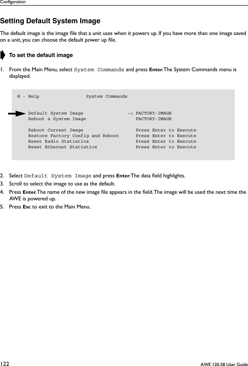
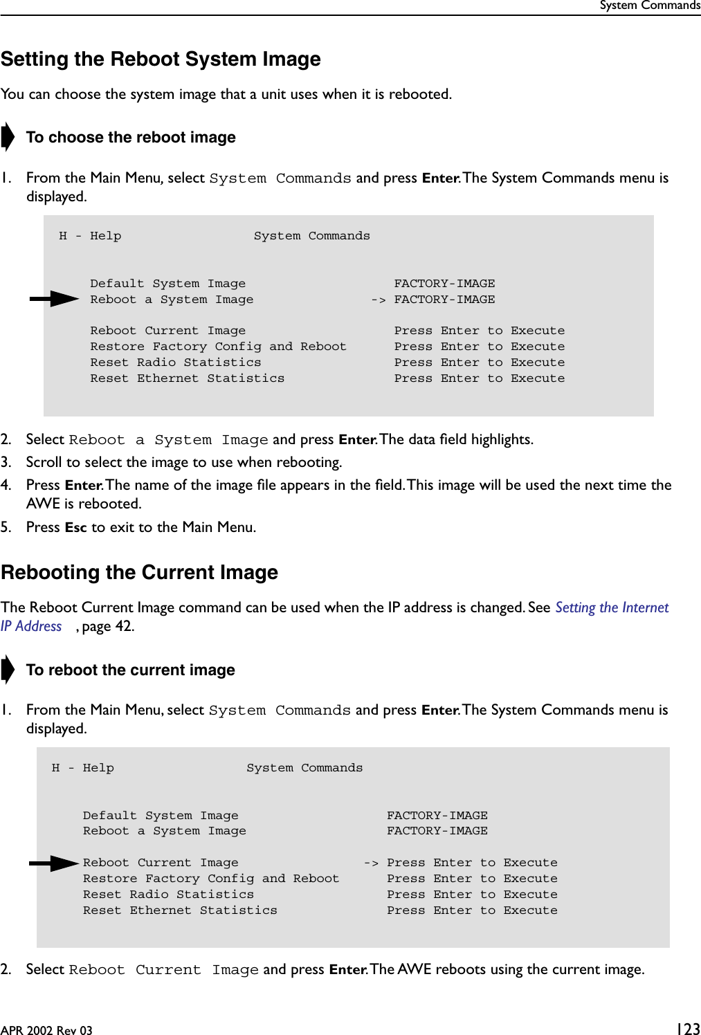
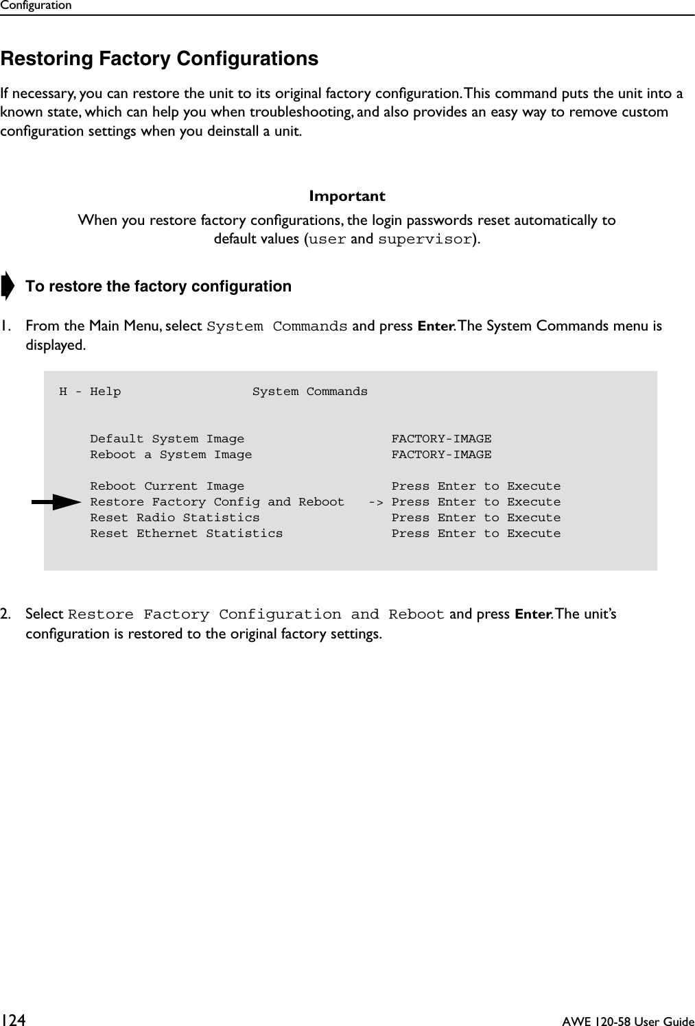
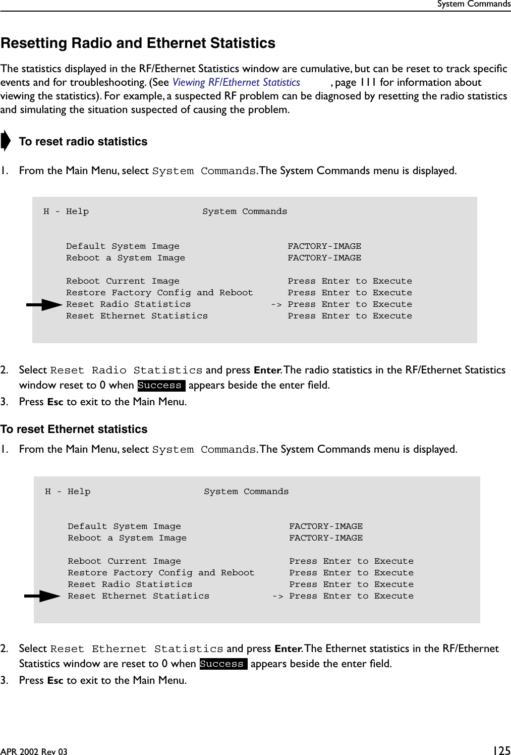
User Manual
Discussion / Help
Navigation