WiSilica WCA2CS WCA2CS User Manual WCA2CS Ver1 1 090818x
WiSilica, Inc. WCA2CS WCA2CS Ver1 1 090818x
WiSilica >
User manual
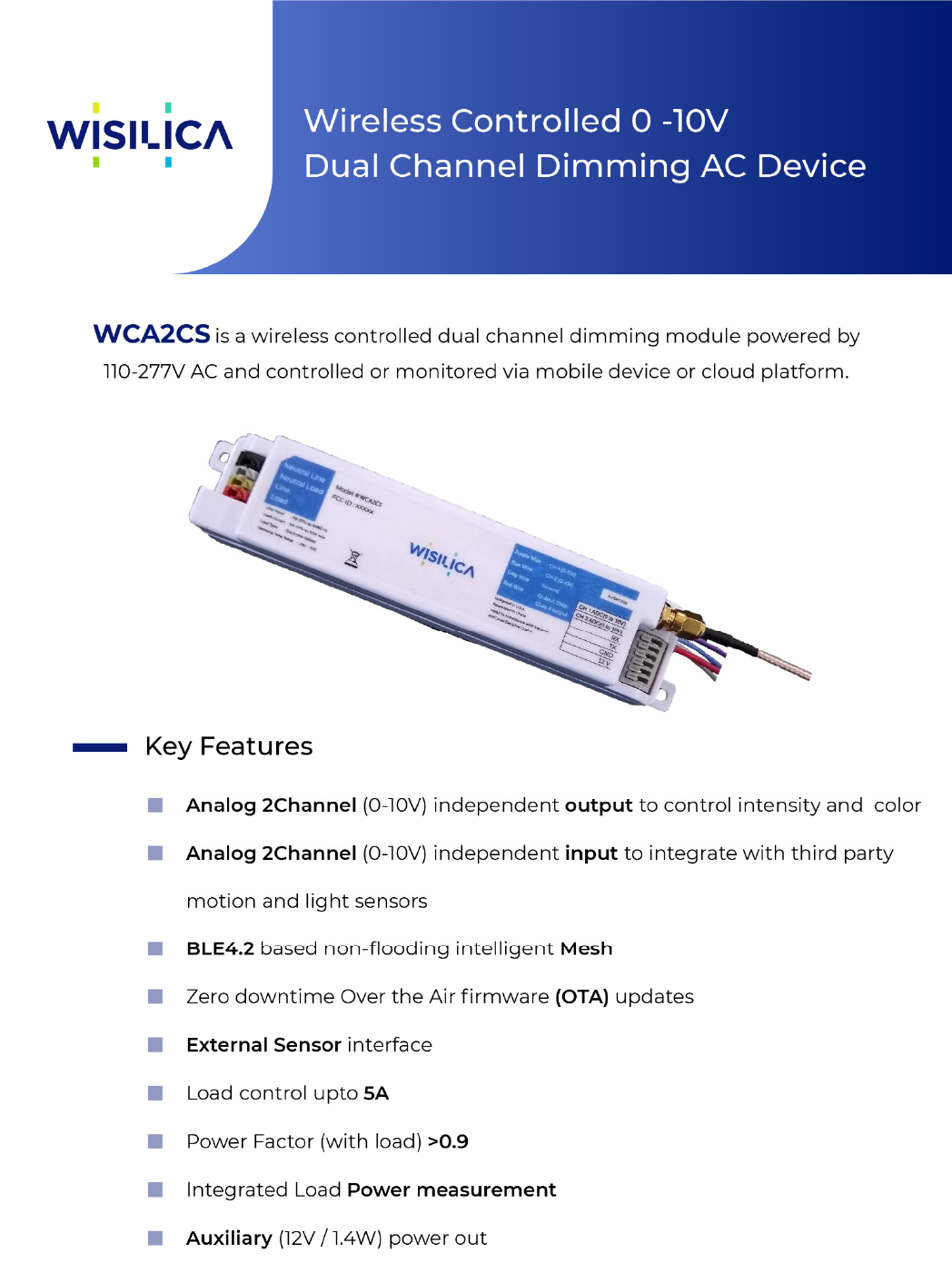
WISILICA NETWORK LIGHTING | CONTROL SERIES
WISILICA NETWORK LIGHTING | CONTROL SERIES
Table of Contents
1. Block Diagram ..................................................................................................................................................... 3
2. Specifications ....................................................................................................................................................... 3
3. Device Dimensions (mm) ................................................................................................................................ 5
4. Connector Description ..................................................................................................................................... 5
5. Wiring Diagram .................................................................................................................................................. 6
6. Use Cases .............................................................................................................................................................. 6
7. User Precautions ................................................................................................................................................ 7
WISILICA NETWORK LIGHTING | CONTROL SERIES
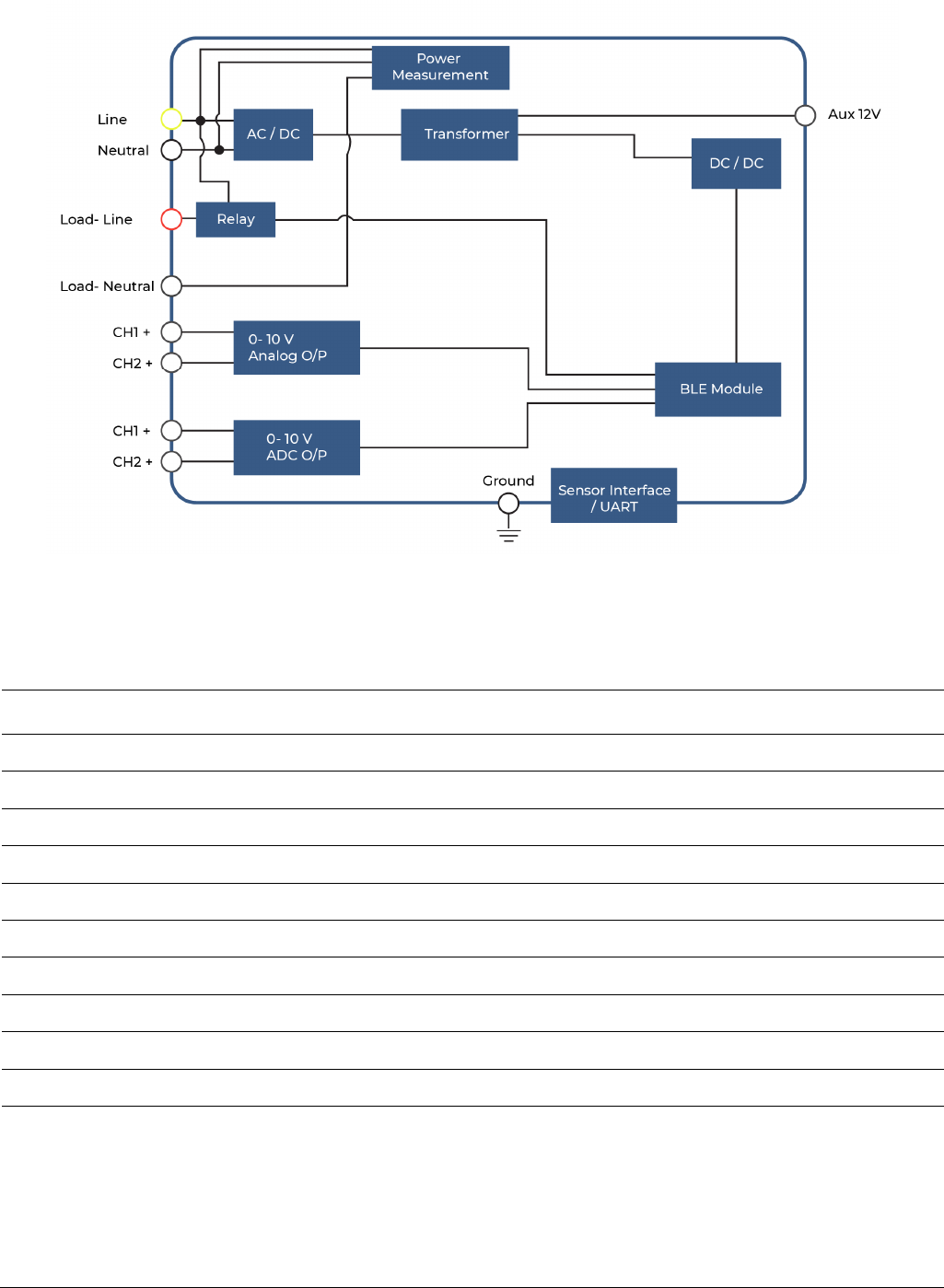
1. Block Diagram
2. Specifications
Electrical Symbol Min Typ. Max. Unit. Remarks
Input Voltage Vin 110 277 Vac Rated Input voltage
Input Current Iin1 60 100 mA @ Max RF transmitting
Power consumption Watt 1.0 3 W Active Power
Input Frequency F 50 - 60 Hz
Protection Class -
Built
-
in
Class II
Suitable for class I and II
luminaries
Inrush Current 20 A
Surge transient Protection 3 kV @Line to Line: Bi-Wave
Leakage Current 0.5 mA @Rated input voltage
Aux power 12V 120mA
Sensor Interface UART

WISILICA NETWORK LIGHTING | CONTROL SERIES
Analogue Dimming Output
Dimming Output1 Vadimo1 0 10 V Max output tolerance ±5%
Dimming Output2 Vadimo2 0 10 V Max output tolerance ±5%
Output Current 15 mA For dimming max output
Dimming Range 0 100 %
Dimming Resolution 8 bit 100 steps
Dimming Curve Linear
Cut Off Voltage 1 V Programmable
Bluetooth
Frequency Range
2400
2483.5
MHz
TX Power
6
8
dBm
Conductive
Frequency Drift(Max)
-
25
25
kHz
dF2
Frequency Deviation
±225
±275
kHz
Carrier Frequency offset
30
150
kHz
TX current
48
mA
Total current@ Max Tx power
Receive Frequency
2400
2483
kHz
Rx Current
-
37
mA
Total Current @Rx Mode
Receiver Sensitivity
-
86
-
75
dBm
Environmental Symbol Min Typ. Max. Unit. Remarks
Ambient Temperature t
a
-20 50 ºC
Storage Temperature t
s
-20 70 ºC
Relative Humidity 85 %
IP Rating IP20 - Indoor use only
Dimensions 175*34*30
mm L x W x H (mm)
Net Weight 80 90 100 g T.B.D
Dimming Type Note
Dimming Control 1 0 – 10V Analog
WISILICA NETWORK LIGHTING | CONTROL SERIES
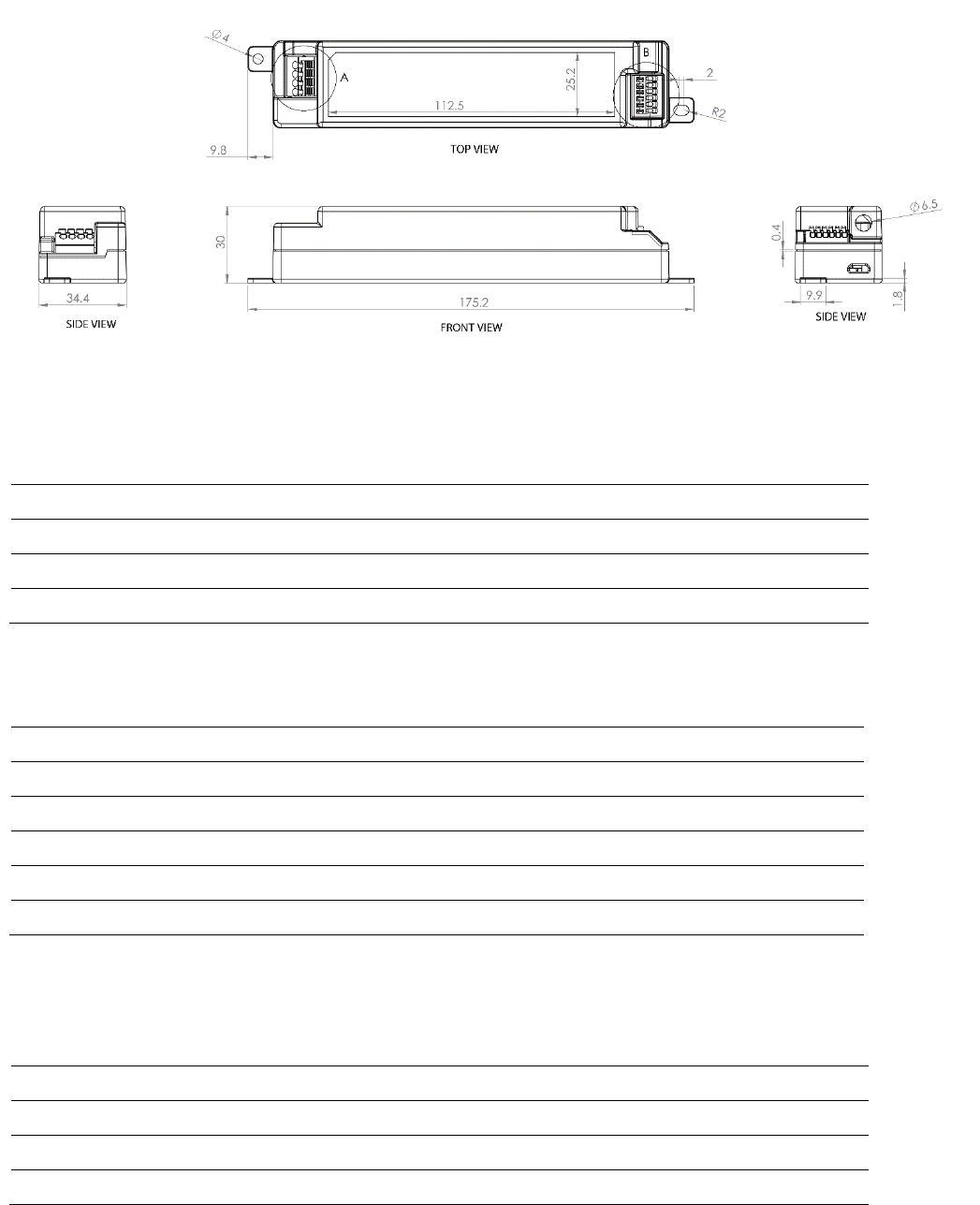
3. Device Dimensions (mm)
Case Material : 5VA
4. Connector Description
PIN SYMBOL COLOR DESCRIPTION
1 Neutral Line Black AC Input Neutral
2 Neutral Load Grey 110-277V ~(Line)
3 Line Yellow 110-277V /5Amps
4
Load
Red
110
-
277V
/5Amps
PIN SYMBOL COLOR DESCRIPTION
1 ADC input Grey CH1 0 to 10V ADC INPUT
2 ADC input Grey CH2 0 to 10V ADC INPUT
3 RX Grey UART
4 TX Grey UART
5 GND Grey 12V Ground Output
6 12V Grey Supports up to 1.4W
5. Wire Description
PIN SYMBOL COLOR DESCRIPTION
1 CH1+ Purple CH1 0 to 10V Analog Output
2 CH2+ Blue CH2 0 to 10V Analog Output
3 GND Grey 12V Ground output
4
12V
Red
12V
WISILICA NETWORK LIGHTING | CONTROL SERIES
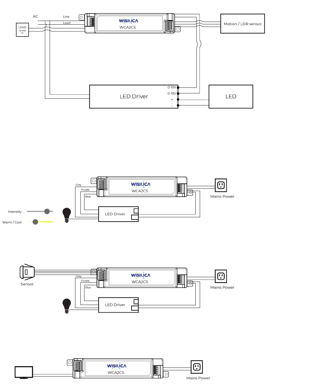
6. Wiring Diagram
7. Use Cases
1. Controlling Intensity and CCT of LED bulb
2. Controlling LED bulb with Sensor Inputs
3. Controlling external load upto 5A
WISILICA NETWORK LIGHTING | CONTROL SERIES
8. User Precautions
• Observe the correct polarity of output terminal.
• Avoid input voltage exceeds the maximum rating, which will cause damage to the circuit and
result in malfunction
• Static electricity or surge voltage may damage the components inside LED Driver, to avoid this
please follow the proper anti-electrostatic working process.
9. FCC Statement
• This equipment has been tested and found to comply with the limits for a Class B digital device,
pursuant to part 15 of the FCC Rules. These limits are designed to provide reasonable protection
against harmful interference in a residential installation. This equipment generates, uses and can
radiate radio frequency energy and, if not installed and used in accordance with the instructions,
may cause harmful interference to radio communications. However, there is no guarantee that
interference will not occur in a particular installation. If this equipment does cause harmful
interference to radio or television reception, which can be determined by turning the equipment
off and on, the user is encouraged to try to correct the interference by one or more of the
following measures:
• Reorient or relocate the receiving antenna.
• Increase the separation between the equipment and receiver.
• Connect the equipment into an outlet on a circuit different from that to which the receiver is
connected.
• Consult the dealer or an experienced radio/TV technician for help.
• Caution: Any changes or modifications to this device not explicitly approved by manufacturer
could void your authority to operate this equipment.
• This device complies with part 15 of the FCC Rules. Operation is subject to the following two
conditions: (1) This device may not cause harmful interference, and (2) this device must accept
any interference received, including interference that may cause undesired operation.
10. RF Exposure Information
• The device has been evaluated to meet general RF exposure requirement. The device can be use
d in portable exposure condition without restriction.