WiSilica WCD2CS WCD2CS User Manual WCD2CS Ver1 080918 rev1 0x
WiSilica, Inc. WCD2CS WCD2CS Ver1 080918 rev1 0x
UserManual.wiki
>
WiSilica
>
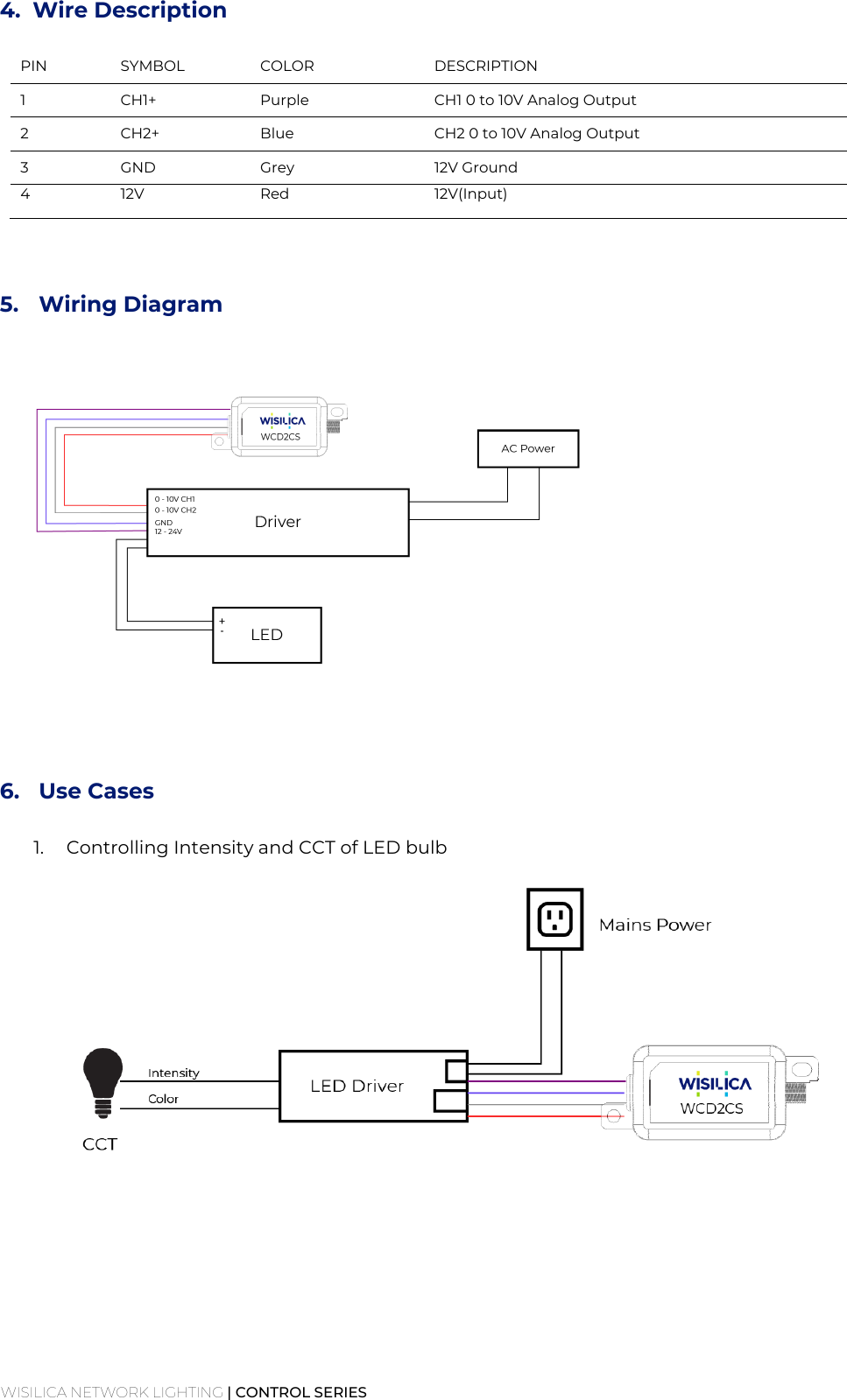
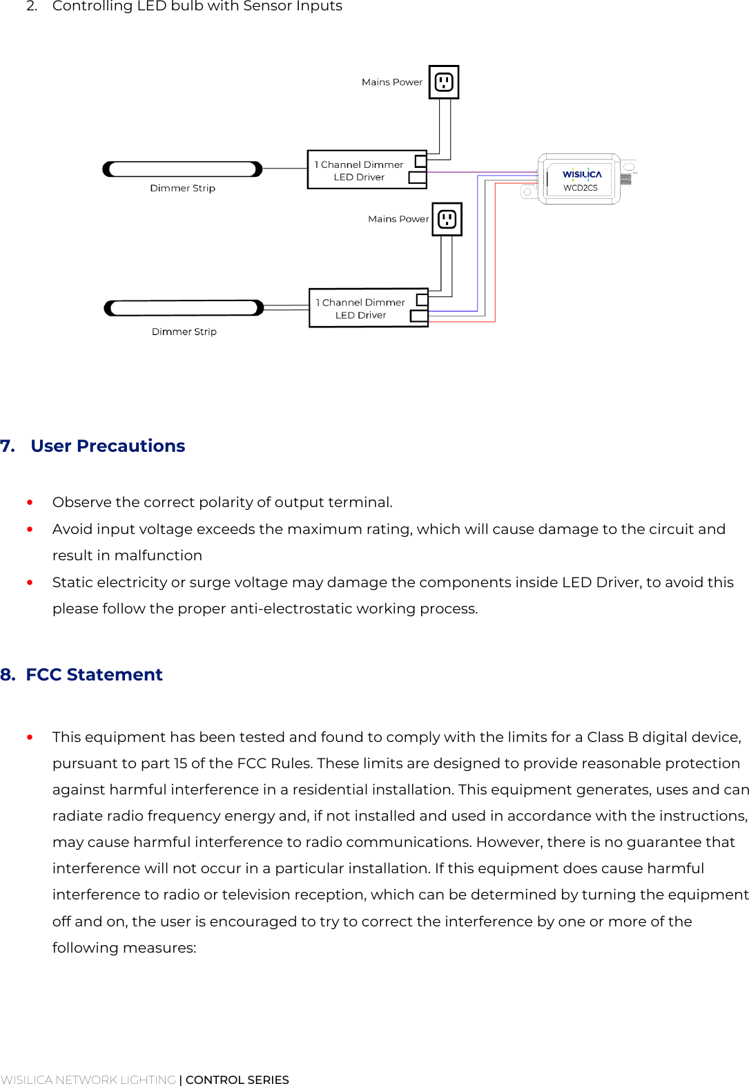
WCD2CS User Manual
User manual
Navigation menu
Upload a User Manual
Namespaces
Wiki Guide
HTML
PDF
Info
Views
User Manual
Discussion / Help
Navigation