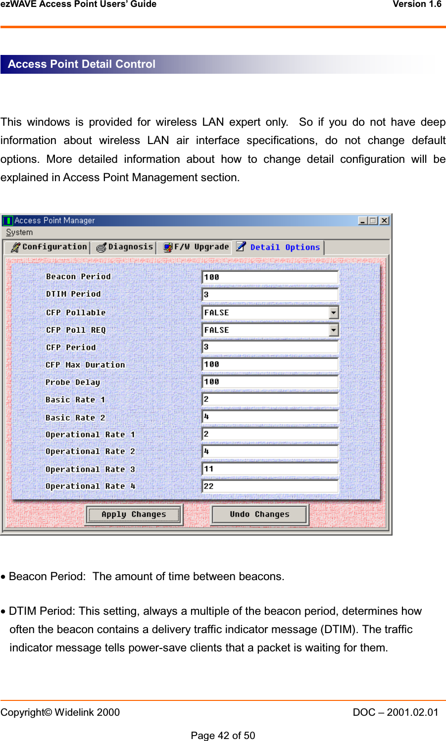
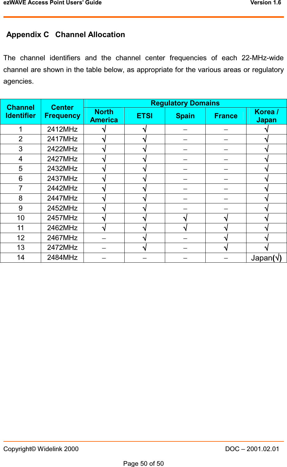
Widelink WAP-1100E 2.4GHz Wireless LAN User Manual WAP 1100E

Widelink Co., Ltd 2.4GHz Wireless LAN WAP 1100E

Contents

users manual

ezWAVE Access Point Users’ Guide Version 1.6 Copyright© Widelink 2000 DOC – 2001.02.01Page 1 of 50 WAP-1100 SeriesWireless LAN Access PointUsers’ GuideCorporate HeadquartersWidelink Co. Ltd.664-25 Dongshin Bldg. 2FShinsa-Dong, Kangnam-guSeoul 135-120, Koreahttp://www.widelink.co.krTel: +82-2-3445-9938Fax: +82-2-3445-8534
ezWAVE Access Point Users’ Guide Version 1.6 Copyright© Widelink 2000 DOC – 2001.02.01Page 2 of 50 ContentsChapter 1 Introduction To The Wireless LAN …………………... 51.1 What is Wireless LAN? ………………………………………51.2 Wireless LAN Standard and Structure……………………………6Chapter 2 Setup ezWAVE Access Point ………………………. 122.1 Before You Begin Installation ……………………………… …. 122.2 Installing The Widelink ezWAVE WAP-1100 Series Access Point……………………………………..14Adjust the antennas ………………………………………… 14Ethernet Cable Connection ………………………………… 15Connect The Power Pack ………………………………….. 16Connect Serial Cable ……………………………………….. 17Open Terminal Program ……………………………………. 18Configuration Change ………………………………………. 212.3 Verifying the Operation of the ezWAVE Access Point ………. 28Chapter 3 Access Point Management……………………….…….303.1 Starting Configuration Tool………………………………………..31Access Point Connection.……………………………………32Access Point Configuration Window..………………………33Terminal Window for Diagnosis …………………………….37Firmware Upgrade Window ………………..……………….38Firmware Upgrade Via Internet …………………………….39Firmware Upgrade Via Local Disk…………………………..41Access Point Detail Control………………………………….423.2 Setting Bridge Mode …………………………………………….. 43Chapter 4 Troubleshooting …………………………………………..45
ezWAVE Access Point Users’ Guide Version 1.6 Copyright© Widelink 2000 DOC – 2001.02.01Page 3 of 50 AppendixAppendix A Cell Planning (Radio Range) ……..………………………………46Appendix B Technical Specification ……………………………………………48Appendix C Channel Allocation ……………………………..………………… .50
ezWAVE Access Point Users’ Guide Version 1.6 Copyright© Widelink 2000 DOC – 2001.02.01Page 4 of 50 THE SPECIFICATIONS AND INFORMATION REGARDING THE PRODUCTS IN THIS MANUAL ARE SUBJECT TOCHANGE WITHOUT NOTICE. ALL STATEMENTS, INFORMATION, AND RECOMMENDATIONS IN THIS MANUALARE BELIEVED TO BE ACCURATE BUT ARE PRESENTED WITHOUT WARRANTY OF ANY KIND, EXPRESS ORIMPLIED. USERS MUST TAKE FULL RESPONSIBILITY FOR THEIR APPLICATION OF ANY PRODUCTS.THE SOFTWARE LICENSE AND LIMITED WARRANTY FOR THE ACCOMPANYING PRODUCT ARE SET FORTH INTHE INFORMATION PACKET THAT SHIPPED WITH THE PRODUCT AND ARE INCORPORATED HEREIN BY THISREFERENCE. IF YOU ARE UNABLE TO LOCATE THE SOFTWARE LICENSE OR LIMITED WARRANTY, CONTACTYOUR WIDELINK REPRESENTATIVE FOR A COPY.NOTWITHSTANDING ANY OTHER WARRANTY HEREIN, ALL DOCUMENT FILES AND SOFTWARE OF THESESUPPLIERS ARE PROVIDED “AS IS” WITH ALL FAULTS. WIDELINK AND THE SUPPLIERS DISCLAIM ALLWARRANTIES, EXPRESSED OR IMPLIED, INCLUDING WITHOUT LIMITATION, THOSE OF MERCHANTABILITY,FITNESS FOR A PARTICULAR PURPOSE AND NONINFRINGEMENT OR ARISING FROM A COURSE OF DEALING,USAGE, OR TRADE PRACTICE.IN NO EVENT SHALL WIDELINK OR ITS SUPPLIERS BE LIABLE FOR ANY INDIRECT, SPECIAL,CONSEQUENTIAL, OR INCIDENTAL DAMAGES, INCLUDING WITHOUT LIMITATION, LOST PROFITS OR LOSSDAMAGE TO DATA ARISING OUT OF THE USE OR INABILITY TO USE THIS MANUAL, EVEN IF WIDELINK OR ITSSUPPLIERS HAVE BEEN ADVISED OF THE POSSIBILITY OF SUCH DAMAGES.SAFETY INFORMATIONWARNING* Opening the unit, for whatever reason, could lead to damages that are not covered by the guarantee.* To prevent fire or shock hazard, do not expose your ezWAVE wireless LAN PC cards to rain or moisture.NOTES:* The Widelink supplied software may show screens slightly different from those included in this manual.* This manual is written based on the assumption that you are familiar with basic operations of Windows operatingsystem.Microsoft Windows, Windows95, Windows98, Windows ME, Windows 2000 and Windows NT are registered trademarksof Microsoft Corporation.ezWave, Widellink’s logo, is registered trademark of Widelink Co., Ltd. or its affiliates in Korea, US and certain othercountries. All other trademarks mentioned in this documents are the property of their respective owners. The use of wordpartner does not imply a partnership relationship between Widelink and any of its resellers.Using the Widelink’s ezWAVE cardCopyrightⓒ2000. Widelink Co., Ltd.All rights reserved.
ezWAVE Access Point Users’ Guide Version 1.6 Copyright© Widelink 2000 DOC – 2001.02.01Page 5 of 50 Chapter 1 Introduction To The Wireless LANA wireless LAN (WLAN) is a flexible data communication system implemented as anextension to, or as an alternative for, a wired LAN within a building or campus. Usingelectromagnetic waves, WLANs transmit and receive data over the air, minimizing theneed for wired connections. Thus, WLANs combine data connectivity with user mobility,and, through simplified configuration, enable movable LANs. WLANs have gained strongpopularity in a number of vertical markets, including the health-care, retail,manufacturing, warehousing, and academic arenas. These industries have profited fromthe productivity gains of using hand-held terminals and notebook computers to transmitreal-time information to centralized hosts for processing. Today WLANs are becomingmore widely recognized as a general-purpose connectivity alternative for a broad rangeof business customers.1.1 What’s Wireless LAN?Wireless LANs use electromagnetic airwaves (radio and infrared) to communicateinformation from one point to another without relying on any physical connection. Radiowaves are often referred to as radio carriers because they simply perform the function ofdelivering energy to a remote receiver. The data being transmitted is superimposed onthe radio carrier so that it can be accurately extracted at the receiving end. This isgenerally referred to as modulation of the carrier by the information being transmitted.Once data is superimposed (modulated) onto the radio carrier, the radio signal occupiesmore than a single frequency, since the frequency or bit rate of the modulatinginformation adds to the carrier.Multiple radio carriers can exist in the same space at the same time without interferingwith each other if the radio waves are transmitted on different radio frequencies. Toextract data, a radio receiver tunes in (or selects) one radio frequency while rejecting allother radio signals on different frequencies.In a typical WLAN configuration, a transmitter/receiver (transceiver) device, called anaccess point, connects to the wired network from a fixed location using standardEthernet cable. At a minimum, the access point receives, buffers, and transmits databetween the WLAN and the wired network infrastructure. A single access point cansupport a small group of users and can function within a range of less than one hundred
ezWAVE Access Point Users’ Guide Version 1.6 Copyright© Widelink 2000 DOC – 2001.02.01Page 6 of 50 to several hundred feet. The access point (or the antenna attached to the access point)is usually mounted high but may be mounted essentially anywhere that is practical aslong as the desired radio coverage is obtained.End users access the WLAN through wireless LAN adapters, which are implemented asPC cards in notebook computers, or use PCI adapters in desktop computers. WLANadapters provide an interface between the client network operating system (NOS) andthe airwaves (via an antenna). The nature of the wireless connection is transparent tothe NOS.1.2 Wireless LAN Standard and Structure{{{{Wireless LAN Standard – IEEE802.11bThe widespread acceptance of WLANs depends on industry standardization to ensureproduct compatibility and reliability among the various manufacturers. The Institute ofElectrical and Electronics Engineers (IEEE) ratified the original 802.11 specifications in1997 as the standard for wireless LANs. That version of 802.11 provides for 1 Mbps and2 Mbps data rates and a set of fundamental signaling methods and other services. Themost critical issue affecting WLAN demand has been limited throughput. The data ratessupported by the original 802.11 standard are too slow to support most general businessrequirements and have slowed adoption of WLANs. Recognizing the critical need tosupport higher data-transmission rates, the IEEE recently ratified the 802.11b standard(also known as 802.11 High Rate) for transmissions of up to 11 Mbps.With 802.11b, WLANs will be able to achieve wireless performance and throughputcomparable to wired Ethernet. Outside of the standards bodies, wireless industry leadershave united to form the Wire-less Ethernet Compatibility Alliance (WECA).WECA’s mission is to certify cross-vendor interoperability and compatibility of IEEE802.11b wireless networking products and to promote that standard for the enterprise,the small business, and the home. Members include WLAN semiconductormanufacturers, WLAN providers, computer system vendors, and software makers.{{{{Wireless LAN Network Equipment802.11 defines two pieces of equipment, a wireless station, which is usually a PCequipped with a wireless network interface card (NIC), and an access point (AP), whichacts as a bridge between the wireless and wired networks. An access point usually
ezWAVE Access Point Users’ Guide Version 1.6 Copyright© Widelink 2000 DOC – 2001.02.01Page 7 of 50 consists of a radio, a wired network interface (e.g., 802.3), and bridging softwareconforming to the 802.1d Bridging standard. The access point acts as the base stationfor the wireless network, aggregating access for multiple wireless stations onto the wirednetwork. Wireless end stations can be 802.11 PC Card and PCI.{{{{Wireless LAN Network ConfigurationThe 802.11 standard define two modes: infrastructure mode and ad hoc mode (orindependent or peer-to-peer).yAd Hoc ModeAd hoc mode (also called peer-to-peer mode or an Independent BasicService Set, or IBSS) is simply a set of 802.11 wireless stations thatcommunicate directly with one another without using an access point or anyconnection to a wired network. This mode is useful for quickly and easilysetting up a wireless network anywhere that a wireless infrastructure does notexist or is not required for services, such as a hotel room, convention center,or airport, or where access to the wired network is barred (such as forconsultants at a client site).Figure 1. Ad Hoc ModeyInfrastructure ModeIn infrastructure mode, the wireless network consists of at least one accessIndependent BasicService Set (IBSS)
ezWAVE Access Point Users’ Guide Version 1.6 Copyright© Widelink 2000 DOC – 2001.02.01Page 8 of 50 point connected to the wired network infrastructure and a set of wireless endstations. This configuration is called a Basic Service Set (BSS). An ExtendedService Set (ESS) is a set of two or more BSSs forming a single sub-network.Since most corporate WLANs require access to the wired LAN for services(file servers, printers, Inter-net links) they will operate in infrastructure mode.Figure 2. Infrastructure Mode{{{{RoamingWireless communication is limited by how far signals carry for given power output.WLANs use cells, called microcells, similar to the cellular telephone system to extendthe range of wireless connectivity. At any point in time, a mobile PC equipped with aWLAN adapter is associated with a single access point and its microcell, or area ofcoverage. Individual microcells overlap to allow continuous communication within wirednetwork. They handle low power signals and “hand off” users as they roam through agiven geographic area.The 802.11 MAC layer is responsible for how a client associates with an access point.Distribution System (DS)Service Set (SS) – MultipleAccess Point (AP)Ethernet (802.3)
ezWAVE Access Point Users’ Guide Version 1.6 Copyright© Widelink 2000 DOC – 2001.02.01Page 9 of 50 When an 802.11 client enters the range of one or more APs, it chooses an access pointto associate with (also called joining a Basic Service Set), based on signal strength andobserved packet error rates. Once accepted by the access point, the client tunes to theradio channel to which the access point is set. Periodically it surveys all 802.11 channelsin order to assess whether a different access point would provide it with betterperformance characteristics. If it determines that this is the case, it re-associates with thenew access point, tuning to the radio channel to which that access point is set. Re-association usually occurs because the wireless station has physically moved away fromthe original access point, causing the signal to weaken. In other cases, Re-associationoccurs due to a change in radio characteristics in the building, or due simply to highnetwork traffic on the original access point. In the latter case this function is known as“load balancing,” since its primary function is to distribute the total WLAN load mostefficiently across the available wireless infrastructure. This process of dynamicallyassociating and re-associating with APs allows network managers to set up WLANs withvery broad coverage by creating a series of overlapping 802.11b cells throughout abuilding or across a campus. To be successful, the IT manager ideally will employ“channel reuse,” taking care to set up each access point on an 802.11 DSSS channelthat does not overlap with a channel used by a neighboring access point.Figure 3. RoamingBackbone NetworkAccess Point (AP)Inter-Cell Roaming
ezWAVE Access Point Users’ Guide Version 1.6 Copyright© Widelink 2000 DOC – 2001.02.01Page 10 of 50 {{{{BSS, ESS and SS IDThe basic service set (BSS) is the basic building block of WLAN network. MinimumWLAN BSS may be consist of only two stations. Using access point (AP) and networkdistribution systems (DS), WLAN service set can be extended arbitrary size – extendedservice set (ESS). Each service set has its network ID (SSID). All the service sets withinan ESS network can have same service ID so that the ESS can support inter-cellROAMING.
ezWAVE Access Point Users’ Guide Version 1.6 Copyright© Widelink 2000 DOC – 2001.02.01Page 11 of 50 Figure 4. SSID and RoamingBackbone NetworkAP #`2 SS ID= WidelinkROAMINGAP #`1 SS ID= WidelinkAP #`3 SS ID=WideESSBSSBackbone NetworkRe-ConfigurationRequired
ezWAVE Access Point Users’ Guide Version 1.6 Copyright© Widelink 2000 DOC – 2001.02.01Page 12 of 50  Chapter 2 Setup ezWAVE Access Point2.1 Before You Begin InstallationThe ezWAVE WAP-1100 Series Access Point is a wireless LAN transceiver that can actas the center point of a stand-alone wireless LAN network or as the connection pointbetween wireless and wired networks. In multiple installations, the roaming functionalityprovided by multiple Access Points allows wireless users to move freely throughout thefacility while maintaining seamless, uninterrupted access to the network. The AccessPoint supports Access Point management software. The system settings are containedon the Access Point's firmware.Before setting up your Access Point, ask your network system administrator for thefollowing information:yYou need an IP (Internet Protocol) address for the Access Point. Each station ordevice on your network must have a unique IP address.yIf there are some Access Points already installed, you need to know their SSID andchannel allocation strategy.yWEP key allocation.CautionYou should configure the Access Point before mounting it on a pole or a ceiling. Someconfiguration steps such as communicating with the Access Point should be donethrough a serial cable may be difficult if the Access Point is inaccessible.Before you begin installation, make sure that you have the following items:yThe ezWAVE WAP-1100 Series Access PointyThe Access Point power supply
ezWAVE Access Point Users’ Guide Version 1.6 Copyright© Widelink 2000 DOC – 2001.02.01Page 13 of 50 yThe ezWAVE WAP-1100 Series Installation CDIf any of these items are missing from the package, contact your Access Point supplier.You will also need:yA computer with serial port (com1, com2) or Ethernet portyA 9-pin, straight-through, male-to-female serial cable
ezWAVE Access Point Users’ Guide Version 1.6 Copyright© Widelink 2000 DOC – 2001.02.01Page 14 of 50 2.2 Installing The Widelink ezWAVE WAP-1100 Series Access PointFollow the instructions below to install the Access Point.For maximum range, make sure the antennas on your Access Point straight up orstraight down, no matter where your Access Point is mounted.If you keep your Access Point on a table or a desk, turn the antennas so they pointstraight up. If you mount your Access Point on a wall or a pole, turn the antennas so theyare vertical, even though the Access Point is on its side. If you mount your Access Pointon the ceiling, turn the antennas so they point straight down.Antenna configurations can be varied depending on the Access Point model, cell coverage or cellplan.STEP 1 Adjust the antennas
ezWAVE Access Point Users’ Guide Version 1.6 Copyright© Widelink 2000 DOC – 2001.02.01Page 15 of 50 Connect the Ethernet cable from your wired LAN to your Access Point.Make sure the unit is not powered up when you connect your network cable.STEP 2 Ethernet Cable Connection
ezWAVE Access Point Users’ Guide Version 1.6 Copyright© Widelink 2000 DOC – 2001.02.01Page 16 of 50  Plug the Power Pack into a wall outlet or a power strip, and plug the connector into thepower receptacle on the back of the Access Point.All three indicators on top of the access point will be bright green.During normal operation, indicators will be bright green. If indicators do not either displaya solid color or blink, see the “Top Panel Indicator Descriptions” in this manual.CautionIf you have already installed Widelink ezWAVE WAP-1100 series client card, you caneasily configure Access Point through air connection between your computer andAccess Point. You may skip next step and go to Access Point Management section.STEP 3 Connect The Power Pack
ezWAVE Access Point Users’ Guide Version 1.6 Copyright© Widelink 2000 DOC – 2001.02.01Page 17 of 50   Use a 9-pin, straight-through, male-to-female serial cable to connect the COM 1 or 2 porton your computer to the RS-232 on the back of the access point. After you find theassigned IP address, you can remove this cable. You might need the cable again if youneed to update the Access Point’s configuration in the future.STEP 4 Connect Serial Cable
ezWAVE Access Point Users’ Guide Version 1.6 Copyright© Widelink 2000 DOC – 2001.02.01Page 18 of 50   Open the HyperTerminal program on the workstation attached to the Access Point.These instructions describe HyperTerminal for example, but you can use any terminal-emulation program to communicate with the Access Point. The following windowappears:Type a name for the connection and click OK. The “Connect To” window appears:STEP 5 Open Terminal Program
ezWAVE Access Point Users’ Guide Version 1.6 Copyright© Widelink 2000 DOC – 2001.02.01Page 19 of 50 Choose the port on your computer to which the serial cable is connected. Click OK.The “port settings” window appears:
ezWAVE Access Point Users’ Guide Version 1.6 Copyright© Widelink 2000 DOC – 2001.02.01Page 20 of 50  Set Bits per second (baud rate) to 19200192001920019200, Data bits to 8888, Parity to NoneNoneNoneNone, Stop bits to 1111, and Flow control to NoneNoneNoneNone. Click OKOKOKOK. The Setup screen appears in the HyperTerminal window. If the text does not appearimmediately, press Enter.If it is successfully connected to Access Point, it will display “prompt” on the terminalprogram’s display box:Type disconfig and press Enter to see the current default settings of Access Point.Make a note of the SSID, Channel number and IP address. Widelink’s Access Point hasa default IP; 100.100.100.100The other options that are displayed can be ignored in this chapter and there will bedetailed explanation on next Access Point Management section
ezWAVE Access Point Users’ Guide Version 1.6 Copyright© Widelink 2000 DOC – 2001.02.01Page 21 of 50 Type setconfig and press Enter to change current default configuration settings. Usingthis command, you can change Access Point’s SSID, Channel number, IP address, MACaddress and WEP key enable/disable.After typing setconfig command, whenever you press Enter key, there will occurchangeable Access Point options and you can select or edit what you want. Refer to thenext example.STEP 6 Configuration Change
ezWAVE Access Point Users’ Guide Version 1.6 Copyright© Widelink 2000 DOC – 2001.02.01Page 22 of 50 The SSID value is case sensitive and can enter up to 32 characters without banks.Available channel numbers varies from country to country. Please refer to the AppendixChannel chapter.In addition to this, it there is Access Points that have already installed in theneighborhood of your Access Point, take a cautious attitude in selecting channel number.Otherwise, by selecting too close channel number with your neighbor Access Point, raisechannel interference problems. This problem can degrade wireless LAN air link qualityseriously. In order to avoid this problem, select a longest channel number with yourneighbor Access Point. RETURN  RETURN
ezWAVE Access Point Users’ Guide Version 1.6 Copyright© Widelink 2000 DOC – 2001.02.01Page 23 of 50 If you use Widelink ezWAVE WAP-1100E as a normal Access Point, select ‘1’.Otherwise, you use it as a point-to-point transmission device you should select ‘2’or‘3’.This usage/process’s detailed explanation will be followed on next chapter.If you know which IP address should be set to your Access Point, then write it in this step.Otherwise if you do not know which IP to be used, ask your network administrator aboutavailable IP address. In this example, the IP address 100.100.100.100 is a default IPaddress that is assigned by Widelink. RETURN  RETURN
ezWAVE Access Point Users’ Guide Version 1.6 Copyright© Widelink 2000 DOC – 2001.02.01Page 24 of 50 WEP stands for Wired Equivalent Privacy. WEP is an encryption scheme that providessecure wireless data communications to the users. WEP uses a 64bit-key or 128bit-keyto control the network access. In order to do secure communication over the wirelessLAN network, enable WEP function.If you enable WEP function, select one of four WEP default key number. You can chooseany number from 1 to 4 and then Exclude Unencrypted question is given. This questionasks you whether you will allow a client that does not use WEP function to accesscommunication with Access Point. Next question is WEP Key Generation Mode. Thereare two ways to generate the WEP key. One is by entering any text in the Passphrase.The other way is by entering Key value directly from the keyboard. In this case, you can
ezWAVE Access Point Users’ Guide Version 1.6 Copyright© Widelink 2000 DOC – 2001.02.01Page 25 of 50 insert any character string.As the wireless channel is more prone to the illegal access, WEP provides the userssafe wireless LAN network access. But if you enable WEP function, it will degradetransmission throughput because it consume time to do encryption/decryption.These options are provided for wireless LAN expert only, so if you does not have deepinformation about wireless LAN air interface specifications, do not change defaultoptions. More detail information about how to change detail configuration will beexplained in Access Point Management section.Now, you have completed all the setup options. Press Enter key. On the Hyper terminalscreen, selected options lists will be displayed. After confirming all the changed options,press y(if you do not need any change) otherwise press n.
ezWAVE Access Point Users’ Guide Version 1.6 Copyright© Widelink 2000 DOC – 2001.02.01Page 26 of 50  If you press ythen Widelink’s Access Point setup configuration will be completed andthe setup program will update changed configuration in the memory.CautionDuring updating configuration data, it might display flash memory write error message. Inthis case, call for assistance from Widelink products’ distributors.
ezWAVE Access Point Users’ Guide Version 1.6 Copyright© Widelink 2000 DOC – 2001.02.01Page 27 of 50
ezWAVE Access Point Users’ Guide Version 1.6 Copyright© Widelink 2000 DOC – 2001.02.01Page 28 of 50 2.3 Verifying the Operation of the Widelink Access PointThe AP runs a series of self-tests on power-up and reports status using its LEDs.When power-up begins, the following occurs:a. The firmware begins running diagnostics and initializes minimal hardware.b. After the firmware completes its diagnostics and hardware initialization. Thediagnostics then checks the RF module to see whether it is properly running the AP.And then, the firmware downloads RF module operating program.c.Upon successful completion of the diagnostics and program download, the LEDwhich shows the wireless LAN link status blinks for 2~3 seconds and then displaybright green light steadily.The diagnostics take approximately 30 seconds to complete after power-up. Uponsuccessful completion of the diagnostics, the LED pattern shown in below figure isdisplayed.If the AP fails to display the proper LED pattern, verify if you have correctly installed theAP. If the AP still fails to display the LED pattern, refer to troubleshooting section.
ezWAVE Access Point Users’ Guide Version 1.6 Copyright© Widelink 2000 DOC – 2001.02.01Page 29 of 50 LED Name Operational StatePower & AP Function On (Green) = power is okayOrange = AP Functional Fail OccurAir Link Status ON (Green) = Air link status okayBlink = Air link or RF modulehas some problems.Ethernet Link Status Blink = Ethernet interface okay andAP is transfering data.Ethernet Link StatusAir Link StatusPower & AP Function
ezWAVE Access Point Users’ Guide Version 1.6 Copyright© Widelink 2000 DOC – 2001.02.01Page 30 of 50 Chapter 3 Access Point ManagementThis chapter describes the pages in the Access Point’s management system.Before installing the Widelink Access Point Manager, first select a computer that meetsthese requirements:•Operating system is Windows 98 and Windows 2000 or Windows ME.•The computer is connected to the Access Point’s wired or wireless LAN.To install the Widelink Access Point Manager, insert the Widelink Access Point setup CDin the PC and run SETUP (this can be done from the Windows Explorer). Follow up thesetup instructions. If you have a previous version of the Access Point Manager, installthe Access Point Manager on the same computer folder. The setup processautomatically upgrades the existing software and keeps your existing configuration files.The Widelink Access Point Manager is included in the Widelink Access Point kit.The AP Manager can be used as a setup/configuration tool for new Access Points andas a management tool to assist the ongoing management and support of Widelinkwireless LANs.The Widelink Access Point Manager has the following features:•Ability to manage multiple APs remotely, including changing parameters in a wirelessnetwork with a single command•Ability to view AP parameters, such as AP statistics, AP firmware version number,MAC addresses•Integrity checking for many wireless parameter changes•Integrated with a BooTP/TFTP application for simple AP firmware upgrades, alsocalled flash upgrades.
ezWAVE Access Point Users’ Guide Version 1.6 Copyright© Widelink 2000 DOC – 2001.02.01Page 31 of 50 3.1 Starting a Configuration ToolTo modify Access Point parameters after installing the Access Point, you need to use adevice connected to the console port or the Widelink Access Point Manager. The formerwas explained in the above chapter. The following sections describe how to configurethe Access Point using Access Point Manager tool.If you have installed the Widelink Access Point Manager on a computer, select:Program Files ¼¼¼¼Widelink ¼¼¼¼ezWAVE Access Point Manager ¼¼¼¼AccessPointManager.exeOr you can simply click the AccessPointManager icon on the windows screen.The program starts with the following screen.
ezWAVE Access Point Users’ Guide Version 1.6 Copyright© Widelink 2000 DOC – 2001.02.01Page 32 of 50 All the Access Points of Widelink have the same default IP address; 211.189.201.251.If you install the Access Point for the first time, you should type Widelink Access Point’sdefault IP on the above IP address input dialog box and then press CONNECT button.If the Access Point has no problem and wire/wireless link is connected without problem.Dialog box pop up to show that the Access Point Manager program is connected to theAccess Point through its IP address.Otherwise if the Access Point Manager program is not able to find the Access Point,then following message is displayed and it will stop the search process.If the Access Point connection fails, verify that you have correctly installed the AP. Andif the AP still fails to connect, refer to troubleshooting chapter.Access Point Connection
ezWAVE Access Point Users’ Guide Version 1.6 Copyright© Widelink 2000 DOC – 2001.02.01Page 33 of 50 Once the Access Point Manager program is successfully connected to an Access Point,all the configuration information are displayed through Access Point Manager program’sconfiguration tab window.•Types: Widelink’s Access Point has multiple functions; Wireless LAN Access Pointand Wireless LAN Bridge for point-to-point transmission. So, this dialog box displayscurrent function mode. Default type value is Access Point mode.•IP Address: This field allows the assignment or change of the Internet Protocol (IP)address of a station.Widelink’s ezWAVE Access Point has a default IP address of - 100.100.100.100.ItisAccess Point Configuration Window
ezWAVE Access Point Users’ Guide Version 1.6 Copyright© Widelink 2000 DOC – 2001.02.01Page 34 of 50 highly recommended that you change the IP address from the default only. You shouldnot use the default IP address, except when you are installing the Access Point for thefirst time.•SSID: The SSID is the network name for your Access Point. All Access Points on thesame LAN must be set with the same SSID in order to support inter-cell roaming.If the Access Point is configured to communicate with wireless clients and the SecureAccess parameter is enabled, each client must be configured with the same SSID. IfSecure Access is not enabled, clients can be configured with the Access Point’swireless network name with word “ANY” (all uppercase/capital letter) or keep theWireless Network Name field blank.•Default Channel: The channel sets the center frequency of the Access Point. In aLAN-to-LAN configuration, the Access Points need to be set to the same channel. In awireless client configuration with multiple Access Points, adjacent Access Pointsshould be set to different channels (at least 5 channels apart recommended).For example, in a configuration with 3 Access Points, set the channels to 1, 6, and 11.Note that some countries only support a limited number of channels. Please refer tothe Appendix Channel section. The Access Point does not allow you to set channelsoutside your country’s band.Wireless clients with ezWAVE PC/PCI Cards automatically switch to the AccessPoint’s channel when roaming between Access Points in a wireless network.•Slave Mac Address: When the Access Point functions as a wireless LAN bridgemaster, it can define the slave bridge’s MAC address.•Ethernet Mac Address: The Media Access Control (MAC) address is a unique serialnumber assigned to a device by the Widelink.•WEP: WEP stands for Wired Equivalent Privacy. WEP is an encryption scheme thatprovides the secure wireless data communications to the users. WEP uses a 64bit-keyor 128bit-key to control the network access. In order to do secure communication overthe wireless LAN network, enable WEP function. Use this setting to choose whether
ezWAVE Access Point Users’ Guide Version 1.6 Copyright© Widelink 2000 DOC – 2001.02.01Page 35 of 50  clients must use data encryption when communicating with this Access Point.•WEP Exclude: WEP Exclude option makes the Access Point service a client that doesnot use WEP function.•WEP Generation: There are two ways to generate the WEP key. One is by enteringany text in the Passphrase. The other way is by entering Key value directly from thekeyboard. In this case, you can insert any character string.•Passphrase: This field allows you to enter any character string to generate Key value.•Key1,2,3and4: These fields allow you to enter the WEP keys. Type tenhexadecimal digits (any combination of 0-9, a-f, or A-F) for 64-bit WEP keys. Toprotect WEP key security, existing WEP keys do not appear in the entry fields. Youcan write over existing keys, but you cannot edit or delete them.CautionThe WEP keys for your network must be set exactly the same as your Access Pointsand your PC LAN cards. The same value must be assigned to Key 1 on both the AccessPoint and the PC LAN cards, the same value must be assigned to Key 2 on both theAccess Point and the PC LAN cards, and so on, for all four WEP keys. For example, ifyou set WEP Key 3 on your Access Point to 0987654321 and select it as the active key,you must also set WEP Key 3 on the PC cards to the same value and select Key 3 astheactivekey.•WEP Default Key: You can choose one of four WEP Keys that have been generatedabove step.•Link Quality: When the Access Point functions as a wireless LAN bridge, it shows link
ezWAVE Access Point Users’ Guide Version 1.6 Copyright© Widelink 2000 DOC – 2001.02.01Page 36 of 50 quality between Master Bridge and Slave Bridge•Signal Strength: When the Access Point functions as a wireless LAN bridge, it showssignal strength between Master Bridge and Slave Bridge•Apply Changes: After entering new values for settings, click Apply Changes button toactivate the new settings.•Undo Changes: If you want to restore Access Point configuration, press this button.
ezWAVE Access Point Users’ Guide Version 1.6 Copyright© Widelink 2000 DOC – 2001.02.01Page 37 of 50 The Diagnosis Tab provides the same function as terminal emulator programs, just likeHyperTerminal program explained in above section.And you can do same things as you use terminal program. Please refer above OpenTerminal Program section.Terminal Window for Diagnosis
ezWAVE Access Point Users’ Guide Version 1.6 Copyright© Widelink 2000 DOC – 2001.02.01Page 38 of 50 Use this page to simultaneously update the Access Point’s system firmware via yourlocal disk or Internet. After making firmware updates on this page, the Access Point willautomatically be rebooted to activate the new firmware.Before you update Access Point’s firmware, you could check current Access Point’sfirmware version through the F/W Upgrade window.The firmware can be updated into two ways; one is via Internet and the other is via localdisk or file server.Firmware Upgrade Window
ezWAVE Access Point Users’ Guide Version 1.6 Copyright© Widelink 2000 DOC – 2001.02.01Page 39 of 50 In order to upgrade Access Point firmware via Internet, click the Internet selectionbutton. If you know an URL address that supply Access Point’s latest firmware versionthen enter the address in the dialog box. Otherwise click Default URL button.The Default URL addresses Widelink’s Internet homepage that supports the latestAccess Point firmware version.If you have defined URL address, press Start button so that the firmware can betransferred to your local disk (Program File ´Widelink ´ezWAVE Access PointManager). During the firmware download, if there is an error or file transfer failure, thenan error message will be displayed.After completing the firmware download, the Manager performs Access Point firmwareupgrade process. This process can be monitored just like as the firmware downloadprocess.Firmware Upgrade Via Internet
ezWAVE Access Point Users’ Guide Version 1.6 Copyright© Widelink 2000 DOC – 2001.02.01Page 40 of 50 If the firmware download processes is completed successfully, download completedmessage is displayed and then Access Point Manager program tries to make a newconnection with the Access Point. Meanwhile, the Access Point that have received thenew firmware version go on self restarts process.
ezWAVE Access Point Users’ Guide Version 1.6 Copyright© Widelink 2000 DOC – 2001.02.01Page 41 of 50 In order to upgrade Access Point firmware via local disk, click the Local Disk button. Inorder to use this option, you should have the latest firmware version in your local diskalready. After you click Browse button, select the firmware that you want to update. Atthis point you should take a special attention in opening the file, to not open a wrong fileor firmware version.After confirming the file name, click the Start button. The other processes from thisstage are same as those of the Internet.Firmware Upgrade Via Local Disk
ezWAVE Access Point Users’ Guide Version 1.6 Copyright© Widelink 2000 DOC – 2001.02.01Page 42 of 50 This windows is provided for wireless LAN expert only. So if you do not have deepinformation about wireless LAN air interface specifications, do not change defaultoptions. More detailed information about how to change detail configuration will beexplained in Access Point Management section.•Beacon Period: The amount of time between beacons.•DTIM Period: This setting, always a multiple of the beacon period, determines howoften the beacon contains a delivery traffic indicator message (DTIM). The trafficindicator message tells power-save clients that a packet is waiting for them.Access Point Detail Control
ezWAVE Access Point Users’ Guide Version 1.6 Copyright© Widelink 2000 DOC – 2001.02.01Page 43 of 50 3.2 Setting Bridge ModeYou can connect two separate LANs over a wireless link by configuring two ezWAVEAccess Points to communicate with each other. This is called a LAN-to-LAN connection.Two Access Points, using outdoor antennas, can connect two buildings or networksegments that use the same communication protocol.To configure two APs to communicate with each other in a LAN-to-LAN configuration,perform the following tasks:1) Get the wireless MAC address of the remote AP. You can see the wireless addressvia the AP Manager or console device, as described in “Access Point ConfigurationWindow“ section. The wireless MAC address is NOT the same as the wired MACaddress printed on the front of the AP.2) Set the Bridge Mode to LAN-to-LAN, as described in above “Access PointConfiguration Window section’s Type item.3) Make sure that the APs use the same channel. To change the AP channel, see“Access Point Configuration Window“ section.The AP provides the following bridging services:•Store-and-forward capabilityThe AP receives, checks, and transmits frames to other LANs, enabling theconfiguration of extended LANs.•Frame filtering based on addressUsing the address database and the source and destination addresses from incomingframes, the AP isolates the traffic that should not be allowed on other LANs. Thisaction reduces the total data traffic on an extended LAN by not forwarding the packetsthat have local destination addresses or packets that are not allowed to forward. Thisincreases bandwidth efficiency.
ezWAVE Access Point Users’ Guide Version 1.6 Copyright© Widelink 2000 DOC – 2001.02.01Page 44 of 50 •Data Link layer relayThe AP operates at the Data Link layer of the Open System Interconnection (OSI)model. Operation at this layer makes the AP transparent to the protocols that use theLAN connectivity service. This protocol transparency is a key factor in the extendedLAN service.
ezWAVE Access Point Users’ Guide Version 1.6 Copyright© Widelink 2000 DOC – 2001.02.01Page 45 of 50 Chapter 4 TroubleshootingT.B.D.
ezWAVE Access Point Users’ Guide Version 1.6 Copyright© Widelink 2000 DOC – 2001.02.01Page 46 of 50 AppendixAppendix A Cell Planning (Radio Range)This section provides general guidelines on factors that influence network performanceCell Site SurveyBecause of differences in component configuration, placement and physical environment,every network application is a unique installation. Before installing the system, usersshould perform a site survey to determine the optimum utilization of networkingcomponents to maximize range, coverage and network performance.Here are some operating and environmental conditions you should consider:•Data RatesRadio signal sensitivity and range are inversely proportional to data bit rates. Themaximum radio range is achieved at the lowest workable data rate. There will be adecrease in receiver threshold sensitivity as the radio data rate increases.•Antenna Type and Placement(PCI card only)Proper antenna configuration is a critical factor in maximizing radio range. As a generalguide, range increases in proportion to antenna height. For a detailed explanation ofantenna types and configurations along with guidelines on selecting antennas forspecific environments, see the documentation that comes with your antenna.•Physical EnvironmentsClear or open areas provide better radio range than closed or filled areas. Also, the lesscluttered the work environment, the greater the range.•ObstructionsA physical obstruction such as metal shelving or a steel pillar can hinder theperformance of the client adapter. Avoid locating the computing device in a locationwhere there is a metal barrier between the sending and receiving antennas.
ezWAVE Access Point Users’ Guide Version 1.6 Copyright© Widelink 2000 DOC – 2001.02.01Page 47 of 50 •Building MaterialsRadio penetration is greatly influenced by the building material used in construction. Forexample, drywall construction allows greater range than concrete blocks. Metal or steelconstruction is a barrier to radio signals.Enhancing CoverageThe system architecture options of the wireless station and ezWAVE Access Pointsprovide for a variety of coverage alternatives and flexibility. The system can be designedto provide a wide coverage area with minimal overlap or coverage with heavy overlap.The latter improves system performance and protection against downtime in the event ofa component failure. By arranging the ezWAVE Access Points to minimize overlap incoverage area, a large area can be covered with minimal system cost. The totalbandwidth available to each mobile station will depend on the amount of data eachmobile station desires to transfer and the number of stations located in each cell.Seamless roaming is supported, as a mobile station moves in and out of range of eachezWAVE Access Point, thereby maintaining a constant connection to the wired LAN.Each device in the radio network must be configured with the same Service Set Identifier(SSID) to provide the roaming capability. Multiple systems can operate in the samevicinity. The architecture provides multiple channels, which can coexist in the same areawith virtually no interference to each other. In this mode, each system must beconfigured with different Service Set Identifiers (SSID) and different channels to preventclients from roaming to ezWAVE Access Points from a different wireless system.
ezWAVE Access Point Users’ Guide Version 1.6 Copyright© Widelink 2000 DOC – 2001.02.01Page 48 of 50 Appendix B Technical SpecificationsFunctional SpecificationItem FunctionConfiguration and setup . Local monitor. Access Point ManagerModes . Access Point. Wireless LAN BridgeStatus Display Power, Air Link Status, Wire Link statusSoftware Upgradeable Via Access Point Manager or local monitorSecurity WEP 64 bit standard, upgradeable to 128 bitApproval WiFi, FCC (processing)Max. No of Clients per AP 255
ezWAVE Access Point Users’ Guide Version 1.6 Copyright© Widelink 2000 DOC – 2001.02.01Page 49 of 50 Electrical/Radio SpecificationsItem Specification DescriptionCompliance IEEE802.11bRadio TypeDirect SequenceSpread-Spectrum(DSSS)2.4 GHz ISM BandOperating Frequency 2400-2483.5 MHz North American, ETSI, and Japanchannel coverage, factory configurableRange Depending on data rateand environment.Accurate values must be calculated forspecific installation.Data Rate 1, 2, 5,5 or 11Mbps Dynamic rate selection based on radiomedium quality.FCC ID FCC approvalNumber of Channels Max 14 Refer Appendix CHANNELChanneling 5 MHz increments Programmable for IEEE 802.11bType of ModulationBPSK 1 Mbit/sQPSK 2 Mbit/sCCK 5.5 and 11 Mbits/sNominal 10 MHz BW(-6 dB)Receiver sensitivity - 84 dBmWired LAN Interface 10Base-T RJ45 ConnectorSerial Interface RS-232 @ 19.2Kbps DB-9 femalePower Consumption 4.5W @ 20°CPower Supply 1.5A DC Input 100-240VAC, 60Hz 5V VDCDimension 157w x 128d x 27h MMWeight 0.5Kg Without antennaOperating Temperature -10°C~+50°CStorage Temperature -20°C~+80°COperating Humidity 10% ~ 90% Non-condensing
ezWAVE Access Point Users’ Guide Version 1.6 Copyright© Widelink 2000 DOC – 2001.02.01Page 50 of 50 Appendix C Channel AllocationThe channel identifiers and the channel center frequencies of each 22-MHz-widechannel are shown in the table below, as appropriate for the various areas or regulatoryagencies.Regulatory DomainsChannelIdentifierCenterFrequency NorthAmerica ETSI Spain France Korea /Japan1 2412MHz √√√√√√√√−−√√√√2 2417MHz √√√√√√√√−−√√√√3 2422MHz √√√√√√√√−−√√√√4 2427MHz √√√√√√√√−−√√√√5 2432MHz √√√√√√√√−−√√√√6 2437MHz √√√√√√√√−−√√√√7 2442MHz √√√√√√√√−−√√√√8 2447MHz √√√√√√√√−−√√√√9 2452MHz √√√√√√√√−−√√√√10 2457MHz √√√√√√√√√√√√√√√√√√√√11 2462MHz √√√√√√√√√√√√√√√√√√√√12 2467MHz −√√√√−√√√√√√√√13 2472MHz −√√√√−√√√√√√√√14 2484MHz −−−−Japan(√√√√)

Navigation menu