Williams Sound T27 AUDITORY ASSISTANCE DEVICE User Manual PPAVP mannew
Williams Sound, LLC AUDITORY ASSISTANCE DEVICE PPAVP mannew
USERS MANUAL

Personal PA™Value Pack System
Wide-Band FM Wireless Listening System
Transmitter Model PPA T27
Receiver Model R35
QUICK SETUP GUIDE
MFRM 010A
Model PPA VP
®
2
SYSTEM OVERVIEW
Thank you for purchasing the Personal PA Value Pack System from Williams Sound
Corporation. The PPA VP System is a Wideband FM Listening System which operates in the
72-76 MHz frequency band. Designed for hearing assistance in places of public access, the PPA
VP is for those who need help overcoming background noise, reverberation, or distance from the
sound source. The versatile PPA VP is easily integrated with your existing sound system or can
be used with a microphone as a stand-alone system.
The system has two principal parts: the T27 Transmitter and the R35 Receiver. Much like a
miniature radio station, the Transmitter and microphone pick up the sounds you want to hear and
broadcast them over an FM radio signal. The receivers are used to pick up the broadcast up to
500 feet away.
To avoid difficulties, please read through these instructions as you begin to use the system. Then
save the manual for questions that arise as you continue to use your PERSONAL PA Value Pack
System.
If you have any problems with this Williams Sound product, don’t hesitate to call us toll-free at
1-800-843-3544.
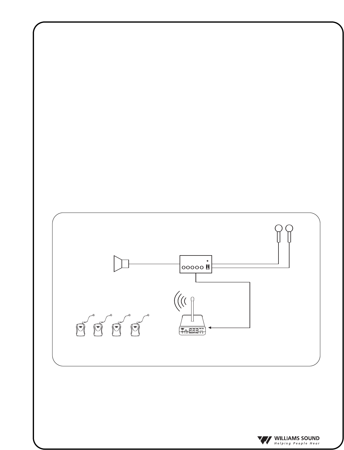
Sound System Amplifier
Loudspeakers
Microphones
Line-Level Output
R35 Wide-band
Receivers w/Earphones
Line-Level Input
T27 Transmitter
FIG.1: OVERALL SYSTEM DIAGRAM

®
3
SETTING UP THE PPA VP
þSTEP 1: SELECT LOCATION
Position the PPA T27 transmitter near the sound system or mixer from which it will receive audio.
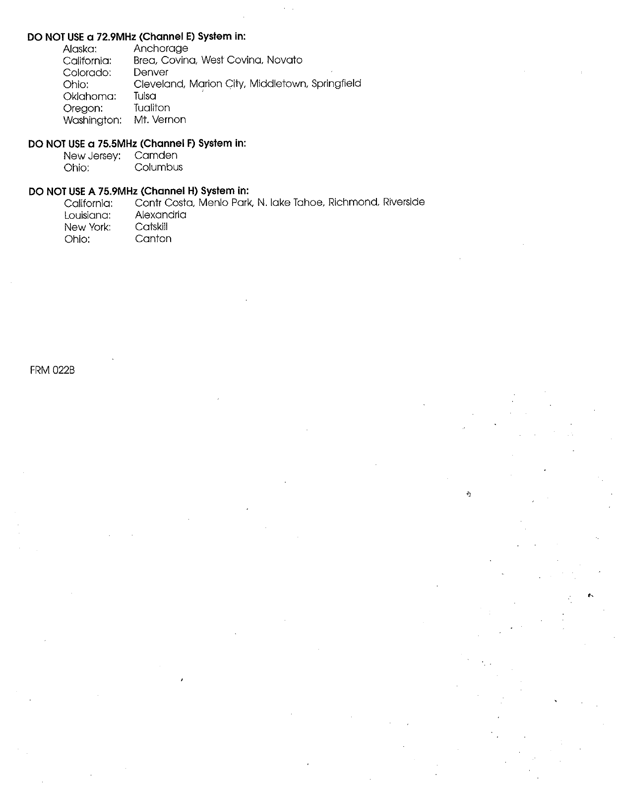
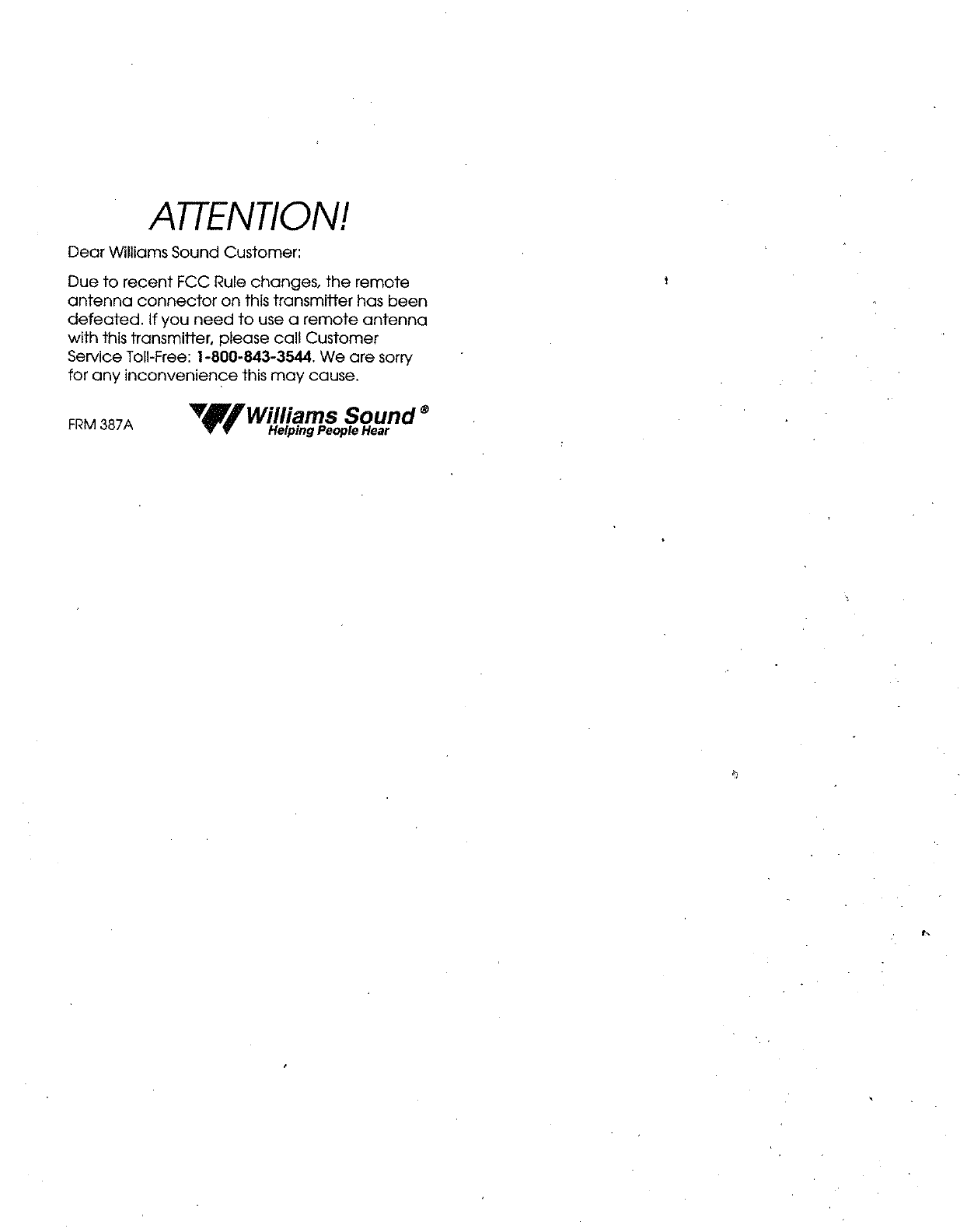
þSTEP 2: INSTALL THE ANTENNA
Gently thread the ANT 021 rubber duckie antenna onto the stud recessed in the hole on the top of the
transmitter. Note: The antenna output on the back of the unit has been defeated, as specified by FCC
Rules. To use a remote antenna, contact your dealer or Williams Sound.
þSTEP 3: CONNECT THE POWER
Locate the power supply cord equipped with the 5-pin DIN connector, then plug the connector into
the “Power In” jack located in the back of the T27. Plug in the power supply into the AC outlet. On
power up, the number “8” will scroll across the T27 display 3 times while the system initializes. The
system will then display the default system frequency (72.9 MHz) or the last selected frequency set
by the user.
þSTEP 4: SELECT THE FREQUENCY
The T27 has 17 available channels in the 72-76 MHz bandwidth. By default, the T27 frequency is
set to 72.900 MHz. To change the frequency on the T27, press and release the down “ ˇ“ or up “ ˆ“
frequency selector button until the desired frequency is displayed. After 3 seconds of no activity, the
frequency selection will be set.
Check to make sure the receiver being used is operating on the same frequency as the trans-
mitter!
NOTE: You can LOCK this selection to prevent others from accidently changing the frequency.
ToLOCK the frequency you have selected, press and hold both down “ ˇ ” and up “ ˆ ” frequency
selector buttons for 3 seconds until the word “Loc” appears on the display. The frequency is now
locked.Should the user press the frequency selector button while in “Lock” mode, the word “Loc”
will be displayed for 2 seconds.
To UNLOCK the frequency selected, press and hold both down “ ˇ ” and up “ ˆ ” frequency selector
buttons for 3 seconds until the transmitter displays ”Un” then “Loc” on the display.The frequency is
now unlocked.The user is now free to change the frequeny channels on the T27 as needed.
FIG 2: Features & Controls
Front View Rear View
1. Mic input jack, 3.5 mm
2. Audio Level Indicator
3. Audio Level Control
4. Frequency Display (LED)
5. Frequency Selector,
Lock/Unlock Control
6. Power Input jack,
12VAC
7.Antenna Connector,
75Ohms
8. Audio input jack, RCA-type
(Line Level, Unbalanced)
1 2 3 4 5 6 7 8

®
4
þSTEP 5: CONNECT THE AUDIO SOURCE
On the back of the T27, an RCA-type “Audio In” jack is available for connecting a line-level, unbal-
anced audio source. On the front of the T27, a 3.5mm “Mic Input” jack is available to connect a
Williams Sound electret microphone. Connect the desired audio source to the T27 transmitter and pro-
ceed to Step 6.
þSTEP 6: ADJUST THE AUDIO LEVEL
With the audio source playing, use a small screwdriver or tuning wand to rotate the “Adjust” control on
the front of the T27 1) clockwise to increase the audio level; or 2) counterclockwise to decrease the
audio level. Refer to the LED audio “Level” indicator on the front of the T27 as you make your adjust-
ments:
Audio Level LED Indicator
1.) Never On =Audio source is TOO LOW.
2.) Blinks occassionally =Audio source is OPTIMAL.
3.) Always on =Audio source is TOO HIGH.
þSTEP 7: LISTEN WITH AN FM RECEIVER
IMPORTANT:The FM receiver being used with the T27 transmitter will need to be on the same
frequency and bandwidth as the transmitter. To retune the FM receiver, follow the tuning instruc-
tions included with that unit. For R35 tuning instructions, see page 6.
Install the receiver batteries, plug in the earphone, turn on the receiver and walk around the listening
area. The signal should be clear and quite loud when the volume is turned up. See pages 5-7 for detailed
R35 receiver instructions.
FCC Warning Statement
Changes or modifications not expressly approved by the party responsible for compliance could void the
user's authority to operate the equipment.
®
5
PPA R35 RECEIVER INSTRUCTIONS
The PPA R35 is a single-channel receiver operating on the 72-76 MHz bandwidth. It features volume on/off
control, LED power and low battery indicator, and an earphone jack. Instructions:
BATTERY INSTALLATION
Install two (2) AA alkaline or NiMH rechargeable batteries. Open the battery compartment by lifting the
tab on the back of the receiver with a finger. To remove depleted batteries, pull up on the fabric strip.
IMPORTANT: If Alkaline (non-rechargeable) batteries are being installed, slide the battery selection
switch above the battery compartment to the “Alkaline” position. If installing NiMH (or rechargeable)
batteries, slide the battery selection switch to the “NiMH” position. Press the batteries into place over
the fabric strip. Be sure to observe proper polarity (+/-). Damage due to improper battery installation
may void the warranty on the product. Close the battery door. When the sound becomes weak or distort-
ed, replace or recharge the batteries.
NOTE: The ON indicator will illuminate RED to indicate low battery.
CONNECTING EARPHONES
Plug the earphone into the “EAR” jack on the top of the unit. Only monophonic earphones will operate
properly. If stereo headphones are used, sound will be heard only in one side of the headphones.
Williams Sound evaluates each earphone and headphone used with the PPA R35 receiver; we can only
assure optimum performance when Williams Sound earphones and headphones are used.
OPERATING THE RECEIVER
NOTE: If you’re using the PPA T27 transmitter, make sure the transmitter is on and receiving good audio
input. Also, make sure the T27 is transmitting on the same frequency as the receiver. If the R35 receiver
needs to be re-tuned (most Williams Sound receivers are set at the factory at 72.9 MHz), see page 6 for fre-
quency change instructions.
Turn the receiver on by rotating the volume control knob clockwise. The receiver’s ON indicator should
illuminate green. Adjust the volume control for your comfort. To turn the receiver off, rotate the volume
control knob counter-clockwise until it clicks off. The receiver’s ON indicator should go dark.
To maximize battery life, remember to turn the receiver off when it’s not in use.
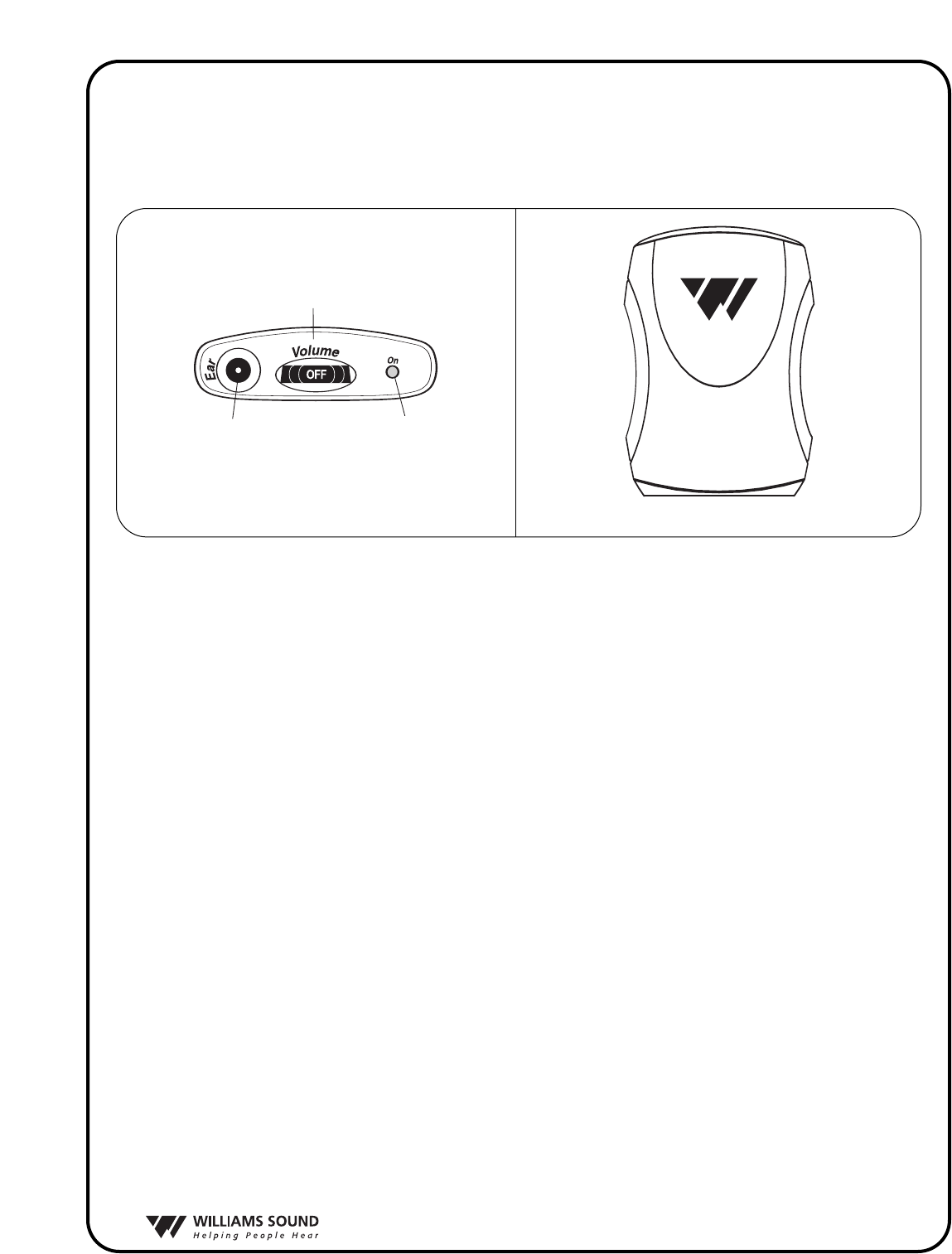
R35 Front
R35 Top
On/Off
Volume Switch
Earphone
Jack
"On" Indicator
LED
R35 Front
R35 Top
On/Off
Volume Switch
Earphone
Jack
"On" Indicator
LED
FIG. 3
R35 Top
R35 Front
®
6
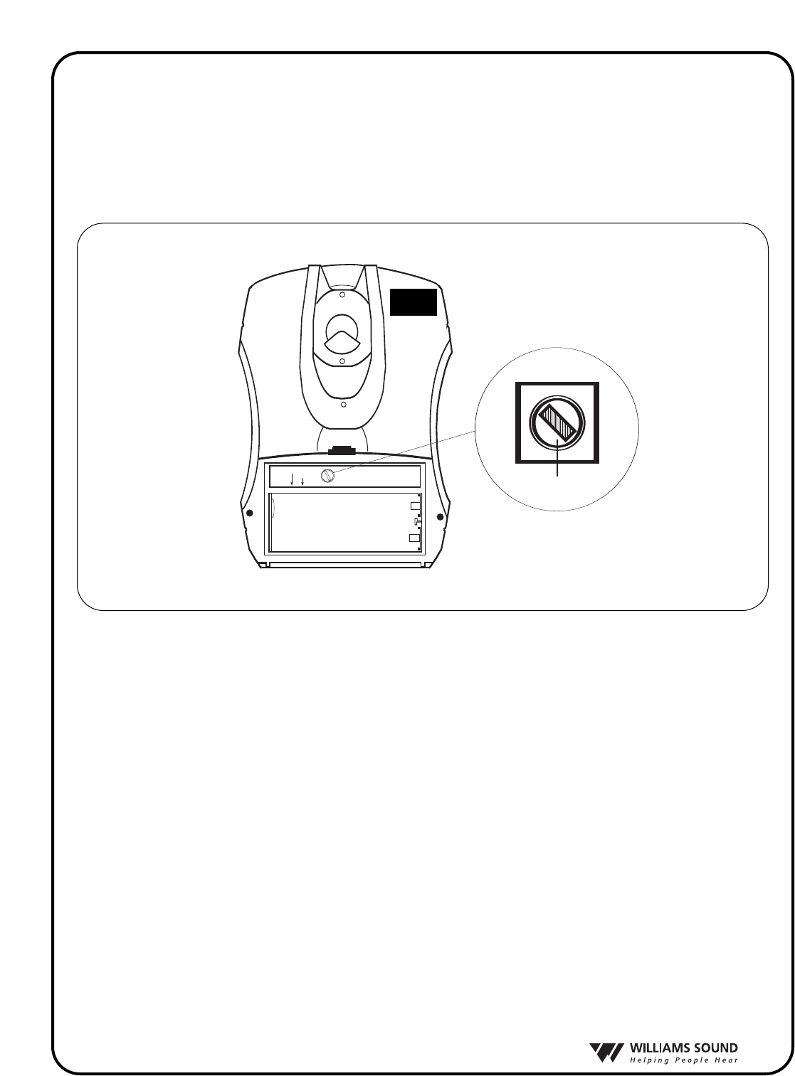
PPA R35 FREQUENCY CHANGE INSTRUCTIONS
Selecting a frequency for the R35 receiver requires an adjustment to the internal tuning coil. See
Figure 4 to locate the coil to be adjusted. A plastic tuning wrench (PLT 005) will be needed to
adjust the receiver’s tuning coil. Note: By default, Williams Sound R35 receivers are set at the facto-
ry to 72.9 MHz.
The Receiver must be tuned with a weak and somewhat noisy signal. If tuned too close to the
transmitter, with a strong signal, the most accurate tuning of the receiver is not possible.
To Change the Frequency to Another Channel:
S
TEP
1: Set the transmitter to the channel desired and remove the antenna.
S
TEP
2: Connect an audio source to the transmitter such as a CD or cassette player or microphone.
S
TEP
3: Move the receiver about 25 feet away from the transmitter to set the tuning.
S
TEP
4: Open the battery compartment.
S
TEP
5: Locate the Tuning Coil (see Figure 4). The tuning coil is a small, square, shiny metal can
with a tuning slug in the top center.
S
TEP
6: With the earphone or headphone supplied with the receiver plugged into the Ear Jack, turn
the volume control to a comfortable level, and listen for the transmitted signal.
S
TEP
7: Gently put the tip of the tuning tool into the slot in the tuning slug. Be careful not to push hard
on the slug so as not to damage the threads in the coil, and do not screw it down more than 3
turns into the coil.
FIG. 4
Channel Tuning
Alkaline
NiMH
Channel Tuning
Alkaline
NiMH
R-35
TUNING COIL
Ferrite Tuning
"Slug"

®
7
STEP 8:Turn the tuning slug in a counter-clockwise direction about two turns. Then, slowly turn
the tuning slug in the clockwise direction until the signal is heard. There may be two
signal points heard. The one which is received first is a false response. Be sure to con
tinue tuning slightly further to the correct point, which will be much louder. Tune back
and forth to find the center of the point of best response to the audio source being
heard.
STEP 9: Mark down the date, and if a new frequency has been chosen, mark it down inside the
receiver case for future reference.

MFRM 010A ©2006 Williams Sound Corp.
®
10321 West 70th St., Eden Prairie, MN 55344 U.S.A.
800.843.3544 | 952.943.2252 | FAX: 952.943.2174
www.williamssound.com