Williams Sound T32 AUDITORY ASSISTANCE DEVICE User Manual Layout 1
Williams Sound, LLC AUDITORY ASSISTANCE DEVICE Layout 1
USERS MANUAL
MAN 126B ©2006 Williams Sound Corp
®
2
®
3
®
®
10321 West 70th St., Eden Prairie, MN 55344 U.S.A.
800.843.3544 | 952.943.2252 | FAX: 952.943.2174
www.williamssound.com
Product Recycling:
Please do NOT dispose of your
Williams Sound equipment in the
household trash. Please take the
equipment to a electronics recy-
cling center; OR, return the product
to the factory for proper disposal.
Battery Recycling:
Please do NOT dispose of used
batteries in the household trash.
Please take the batteries to a retail
or community collection point for
recycling.
9/19/06
OPERATING INSTRUCTIONS
1. Install two (2) AA batteries. If
you’re using rechargeable
batteries, they must be
charged before using.
2. Plug the microphone cord
into the “Mic” jack on top of
the transmitter.
3. Place the transmitter in the
belt clip case provided.
4. Slide the Power Switch on top
of the transmitter to “On.” The
Power ON LED indicator
should illuminate Red.
5. The microphone should be
placed as close to the speaker’s
mouth as is practical. For lapel
mics, attach the microphone to
acollar, lapel, or tie.
6. When you are ready to speak, turn
the Mic Mute Switch (speaker
icon) to the “On” position. When
you are done speaking, mute the
mic by turning the Mute Switch to
the “Off” position (speaker icon
with line through it).
The transmitter can be placed in
apants pocket, or clipped onto a
belt or waistband.
Important: To conserve battery
life, remember to turn the trans-
mitter OFF when it is not in use.
Note On The Transmitter Antenna:
The microphone cord is the trans-
mitting antenna. Do not bunch up
the cord or wrap it around the
Thank you for purchasing the PFM T32 transmitter from Williams Sound. The
T32 is designed to operate with a wideband FM, 72–76 MHz receiver. For more
information on available receivers, contact Williams Sound at 800-843-3544.
How the system works: The PFM T32 transmitter uses a microphone (not
included) to pick up the desired sound source. The speaker talks into the micro-
phone and the T32 transmitter broadcasts the message over an FM radio signal.
Listeners wear FM receivers equipped with headphones to pickup the broadcast
and hear the speaker’s message.
Hearing Helper™Transmitter, Model PFM T32
Instructions For Use and Care
PACEMAKER SAFETY
1. Before using this product with
apacemaker or other medical
device, consult your physician
or the manufacturer of your
pacemaker or other medical
device.
2. If you have a pacemaker or
other medical device, make
sure that you are using this
product in accordance with
safety guidelines established
by your physician or the pace-
maker manufacturer.
BATTERY SAFETY & DISPOSAL
Do not attempt to recharge dis-
posable batteries, which may
explode, release dangerous chem-
icals, cause burns, or other seri-
ous harm to the user or product.
RECYCLING INSTRUCTIONS
Help Williams Sound protect the envi-
ronment! Please take the time to dis-
pose of your equipment properly.
CAUTION! CAUTION!
transmitter. For maximum
range, the cord should hang as
straight as possible.
BATTERY INSTRUCTIONS
This transmitter can use dispos-
able AA batteries (alkaline or
NiMH) or a Williams Sound
rechargeable battery (BAT 026).
We recommend using BAT 026
AA NiMH or BAT 001 AA
Alkaline batteries. BAT 026 bat-
teries will last about 20 hours per
charge when used with Williams
Sound transmitters. BAT001 bat-
teries will last approx. 30 hours
when used with Williams Sound
transmitters. Batteries from other
suppliers may provide different
operating life.
Low Battery Indicator
The power ON LED indicator will
flash to indicate low battery. A
soft pulsing sound may be heard
on the receiver(s) being used.
EXPECTED BATTERY LIFE
Alkaline batteries
(BAT 001):30 hrs.
Rechargeable NiMH Batteries
(BAT 026):20 hrs. per charge.
Min. 14 hour recharge time.
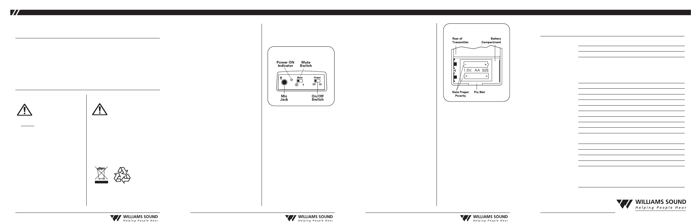
INSTALLING AND REPLACING BATTERIES
1. Open the battery compartment
by lifting the tab on the bottom
of the transmitter with a coin or
finger.
2. Toremove depleted batteries,
pull up on the fabric strip.
3. To install new batteries, press
them into place over the fabric
strip. Be sure to observe proper
polarity (+/–).
4. Close the lid.
5. When the sound becomes
weak or distorted, replace or
recharge batteries. If recharg-
ing, use the Williams Sound
CHG 200 Battery Charger.
FIG 1: PFM T32 Top View
FIG 2: T32 Battery Compartment
Dimensions: 3-5/8" L x 2-3/8" W x 7/8" H (92.1 mm x 60.3 mm x 22.2 mm)
Weight: 4.4 oz (125 g) with battery
Color: Royal blue, shatter-resistant polypropylene
Battery Type: Two (2) AA 1.5 V non-rechargeable Alkaline batteries (BAT 001),
70 mA nominal current drain, 30 hours approx. life
(OR) Two (2) AA 1.5 V NiMH rechargeable batteries (BAT 026),
70 mA nominal current drain, 20 hours per charge approx.,
recharges in 14–16 hours, uses CHG 200 or CHG 1600 Charger
Operating Freq’s: Selectable, 16 channels, 72.1 – 75.9 MHz, internal rotary switch
Stability: ±.005%, frequency synthesized, crystal reference, PLL
Modulation: Wide-band FM, 75 kHz pk, 75 µS pre-emphasis
RF Output: 8000 µV/m at 30 m, max., 40 mW typical
Freq Response: 200 to 10 kHz, + 3 dB at 1% max. THD
Signal-to-Noise Ratio: 55 - 60 dB, with R31 or R32 Receiver
Microphone Gain Control: 45 dB maximum, 18 dB minimum range
Transmit Antenna: Integral with 39" microphone cord
Microphone: Electret type, 39" cord, 3.5 mm mono phone plug
Controls: On/Off switch, slide-type; Microphone Mute Switch, slide-type;
Compression Selector 1:1 or 2:1 with internal selectable jumper
Mic Connector: 3.5 mm mono phone jack
Compatible Receivers: PPAR35, PFM R31, PFM R32
Approvals: FCC, Industry Canada, RoHS, WEEE
Warranty: 5years, parts and labor (90 days on accessories)
Note:
FCC regulations, section 15.21, requires the user to comply with the rules
of transmitter operation. Any changes or modifications made by the user
not expressly approved for compliance may result in the loss of all privi-
leges and authority to operate the equipment.
SYSTEM SPECIFICATIONS
H
EARING
H
ELPER
™PFM T32 T
RANSMITTER
MAN 126B ©2006 Williams Sound Corp
INCIDENTAL OR CONSEQUEN-
TIAL DAMAGES CAUSED BY
ANY USE, DEFECT, FAILURE OR
MALFUNCTION OF THE PROD-
UCT, WHETHER A CLAIM FOR
SUCH DAMAGES IS BASED
UPON WARRANTY, CONTRACT,
TORT OR OTHERWISE. THE
SOLE REMEDY FOR ANY
DEFECT, FAILURE OR MALFUNC-
TION OF THE PRODUCT IS
REPLACEMENT OF THE PROD-
UCT. NO PERSON HAS ANY
AUTHORITY TO BIND WILLIAMS
SOUND TO ANY REPRESENTA-
TION OR WARRANTY WITH
RESPECT TO THE PFM T32
TRANSMITTER. UNAUTHO-
RIZED REPAIRS OR MODIFICA-
TIONS WILL VOID THE WARRAN-
TY.
The exclusions and limitations set out
above are not intended to, and should
not be construed so as to contravene
mandatory provisions of applicable
law. If any part or term of this
Disclaimer of Warranty is held to be
illegal, unenforceable or in conflict
with applicable law by a court of
competent jurisdiction, the validity of
the remaining portions of this
Disclaimer of Warranty shall not be
affected, and all rights and obligations
shall be construed and enforced as if
this Limited Warranty did not contain
the particular part or term held to be
invalid.
If you experience difficulty with your
system, call Toll-Free for Customer
Assistance:
1-800-843-3544
If it is necessary to return the system
for service, your Customer Service
Representative will give you a Return
Authorization Number (RA) and
shipping instructions.
Pack the system carefully and
send it to:
Williams Sound Corp.
Attn: Repair Dept.
10321 West 70th Street
Eden Prairie, MN 55344
4
®
5
®
6
®
7
®
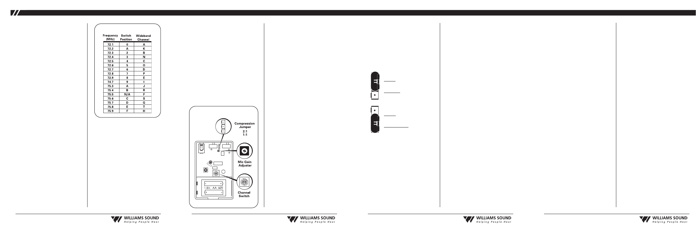
CHANGING FREQUENCIES
By default, the T32’s frequency
is to set 75.7 MHz (Channel G).
If you experience FM interfer-
ence, or if you need to match a
receiver’s frequency, it may be
necessary to adjust the frequency
on the T32. Instructions:
1. Open the battery compartment
using a coin in the slot in the
bottom of the transmitter.
Remove the batteries.
2. Lift the battery compartment
door up and pull to your left to
expose the circuit board.
3. Refer to FIG 4 to locate the
Channel Switch.
4. Use a small screwdriver to
rotate the Channel Switch to
correspond with the desired
operating frequency. Choose
between 16 standard channels.
Refer to the Channel Selection
Chart in FIG 3 for available
channels.
5. Reinstall the batteries, then
close the back of the transmitter.
6. Plug the microphone in and turn
the transmitter on to provide a
tuning signal for the receivers.
Makesureall receiversbeing
used match the frequency of
the transmitter.Refer to the
receiver’sinstruction manual
for frequency change instruc-
tions.
ADVANCED FEATURES
Gain Control Adjustment
If necessary, the microphone gain
control on the T32 can be
increased or decreased to meet
the demands of specific listening
applications.
Instructions:
1. Open the battery compartment
using a coin in the slot in the
bottom of the transmitter.
Remove the batteries.
2. Lift the battery compartment
door up and pull to your left to
expose the circuit board.
3. Refer to FIG 4 to locate the
microphone gain control.
4. Using a small screwdriver, turn
the gain control fully counter-
clockwise to reduce the gain.
Turn the gain control fully
clockwise to increase the gain
5. Close the back of the case and
battery door.
COMPRESSION ADJUSTMENT
By default, the T32 transmitter
compression jumper is set to
“Off” for normal operation, or
1:1 compression. For hearing
assistance applications, the com-
pression jumper can be set to
“On” for 2:1 compression.
Instructions:
1. Open the battery compartment
using a coin in the slot in the
bottom of the transmitter.
Remove the batteries.
2. Lift the battery compartment
door up and pull to your left to
expose the circuit board.
FIG 3: Channel Selection Chart 3. Refer to FIG 4 to locate the
Compression Selector.
4. Gently remove the jumper
from the circuit board by
pulling it up and away from
the unit. You will see three
exposed “pins.”
Toturn compression
“On” (2:1 Compression):
Press jumper on to the
top twopin locations as
shown on left.
Toturn compression
“Off” (1:1 Compression):
Press jumper on to the
bottom twopin locations
as shown on left.
5. Close the back of the case and
battery door.
LIMITED WARRANTY
Williams Sound products are engi-
neered, designed and manufactured
under carefully controlled conditions
to provide you with many years of
reliable service. Williams Sound
warrants the PFM T32 transmitter
against defects in materials and work-
manship for FIVE (5) years. During
the first five years from the purchase
date, we will promptly repair or
replace the PFM T32 transmitter.
Earphones, headphones, batteries,
cables, carry cases, and all other
accessory products carry a 90-day
warranty.
WILLIAMS SOUND HAS NO
CONTROL OVER THE CONDI-
TIONS UNDER WHICH THIS
PRODUCT IS USED. WILLIAMS
SOUND, THEREFORE, DIS-
CLAIMS ALL WARRANTIES NOT
SET FORTH ABOVE, BOTH
EXPRESS AND IMPLIED, WITH
RESPECT TO THE PFM T32
TRANSMITTER, INCLUDING
BUT NOT LIMITED TO, ANY
IMPLIED WARRANTY OF MER-
CHANTABILITY OR FITNESS
FOR A PARTICULAR PURPOSE.
WILLIAMS SOUND SHALL NOT
BE LIABLE TOANY PERSON OR
ENTITY FOR ANY MEDICAL
EXPENSES OR ANY DIRECT,
FIG 4: T32 Back View (open)