Williams Sound T36 AUDITORY ASSISTANCE DEVICE User Manual MAN142A T36
Williams Sound, LLC AUDITORY ASSISTANCE DEVICE MAN142A T36
USERS MANUAL
MAN 142A ©2008 Williams Sound Corp.
®
Thank you for purchasing the T36 transmitter from Williams Sound. The
T36 is designed to operate with a wideband FM, 72–76 MHz receiver.
For more information on available receivers, contact Williams Sound at
800-843-3544 or 952-943-2252
Transmitter Model T36, 72-76 MHz
Instructions For Use and Care
PACEMAKER SAFETY
1. Before using this product with a
pacemaker or other medical device,
consult your physician or the man-
ufacturer of your pacemaker or
other medical device.
2. If you have a pacemaker or other
medical device, make sure that you
are using this product in accordance
with safety guidelines established by
your physician or the pacemaker
manufacturer.
BATTERY SAFETY & DISPOSAL
Do not attempt to recharge disposable
batteries, which may explode, release
dangerous chemicals, cause burns, or
other serious harm to the user or
product.
RECYCLING INSTRUCTIONS
Help Williams Sound protect the
environment! Please take the
time to dispose of your equipment
properly.
Product Recycling:
Please do NOT dispose of your
Williams Sound equipment in the
household trash. Please take the
equipment to an electronics recy-
cling center; OR, return the product
to the factory for proper disposal.
Battery Recycling:
Please do NOT dispose of used
batteries in the household trash.
Please take the batteries to a retail
or community collection point for
recycling.
05/22/08
CAUTION!
CAUTION!
2
®
OPERATING INSTRUCTIONS
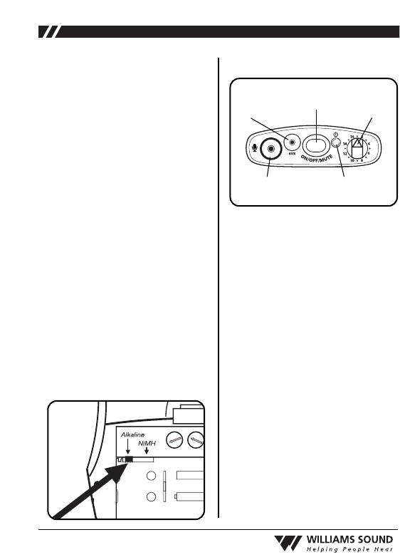
IMPORTANT: If Alkaline (non-
rechargeable) batteries are being
installed, slide the battery selection
switch in the battery compartment to
the “Alkaline” position. See FIG. A
below. If installing NiMH (or recharge-
able) batteries, slide the battery selec-
tion switch to the “NiMH” position.
1. Install AA batteries: Open the battery
compartment by lifting the tab on the
back of the transmitter with your fin-
ger. To remove depleted batteries,
pull up on the fabric strip.
Press the batteries into place over the
fabric strip. Be sure to observe proper
polarity (+/-). Damage due to
improper battery installation may
void the warranty on the product.
Close the battery door. LED will
flash when the batteries are getting
low; continue to use until the unit
quits operating, then replace or
recharge batteries.
Mic Jack
Channel
Selector
Power On Indicator
Auxiliary
Input
Power ON/Off/Mute
2. Plug the microphone cord (sold sep-
arately) into the “Mic Jack” on top
of the transmitter (FIG. B).
Alternatively, plug in a desired
audio source such as a CD or MP3
player using the “Auxiliary Input”
jack (WCA 087 auxiliary input
cable included). If mic and auxiliary
sources are used together, the audio
will be mixed.
3. Turn the unit on: press and hold the
“ON/OFF/MUTE” button for three
seconds. The “Power ON Indicator”
should illuminate Green.
4.
Select the desired operating frequen-
cy. Use the “Channel Selector” knob
to select any of the 16 available chan-
nels on 72-76 MHz. Refer to the
channel selection chart, FIG C.
IMPORTANT: Make sure the receiv-
er being used is operating on the same
frequency as the T36 transmitter!
AA
AA
–
+
-
Gain
+-
AUX
+
2:1
1:1
FIG. A: Battery Selection Switch
FIG. B: T36 User Controls
3
®
5. Position the headset microphone
boom as close to the speaker’s mouth
as possible without actually touching.
Lapel clip microphones should be
attached to a collar or lapel, as close
to the speaker’s mouth as possible.
The transmitter can be placed in a
pocket, or clipped onto a belt or
waistband.
6.
When you pause from speaking, mute
the microphone by pressing the
“ON/OFF/MUTE” button once
momentarily. The ON/OFF/MUTE
button will flash RED. To unmute the
mic, press the ON/OFF/MUTE button
once momentarily again.
IMPORTANT:
When the T36 trans-
mitter is not being used, remember to
turn the unit OFF by pressing and hold-
ing the ON/OFF/MUTE button for three
seconds. The Power ON Indicator
should not be lit.
GAIN CONTROL
The gain control can be used to adjust the
volume level on both the microphone and
auxiliary input.
To adjust the volume level, open the bat-
tery door and locate the Gain Control (FIG.
D). To increase the volume, use a plastic
tuning wand and turn the “Gain” control
clockwise. To decrease the volume, turn
the “Gain” control counterclockwise. Close
the battery door after adjustments have
been made.
AUXILIARY INPUT LEVEL
The auxiliary input level can be used to
adjust the auxiliary input level only.
To adjust, open the battery door and locate
the Auxiliary Input Level (FIG. D). To
increase the input level, use a plastic tuning
wand and turn the “AUX” control clock-
wise. To decrease the auxiliary input level,
turn the AUX control counterclockwise.
Close the battery door after adjustments
have been made.
AA
AA
–
+
+
–
Comp
CH Lock
-
Gain
+-
AUX
+
22:1
1:1
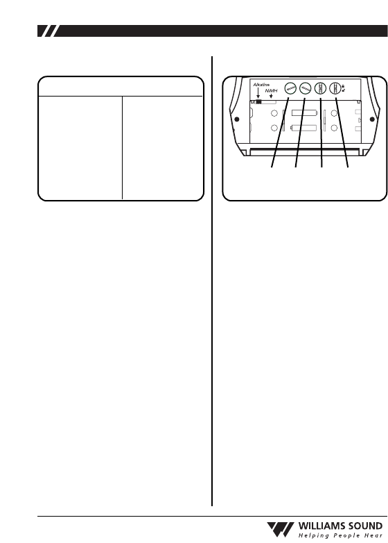
1. Gain Control
2. Auxiliary Input Level
3. Compression Selector
4. Channel Lock
1234
CH
1
2
3
4
5
6
7
8
Freq.
72.1 MHz
72.2 MHz
72.3 MHz
72.4 MHz
72.5 MHz
72.6 MHz
72.7 MHz
72.8 MHz
CH
9
10
11
12
13
14
15
16
Freq.
72.9 MHz
74.7 MHz
75.3 MHz
75.4 MHz
75.6 MHz
75.7 MHz
75.8 MHz
75.9 MHz
FIG. C: Channel Selection Chart FIG. D: Configuration Controls

4
®
COMPRESSION SELECTOR
By default, the T36 transmitter is set to
“Off” for normal operation, or 1:1
compression. For hearing assistance
applications, the compression selector
can be set to “On” for 2:1 compres-
sion.
To change this setting, open the battery
door and locate the Compression
Selector (FIG. D).
To turn on compression (2:1), use a
plastic tuning wand and slide the
“Compress” switch to the position
marked “2:1.” To turn off compres-
sion, slide the “Compress” switch to
the position marked “1:1.” Close the
battery door after adjustments have
been made.
CHANNEL LOCK
By default, the T36 channels are
unlocked to allow the user to change
frequencies as needed. If desired,
channels can be locked to prevent
users from changing the channels.
To lock or unlock channels, open the
battery door and locate the Channel
Lock (FIG. D). To lock the channels,
slide the “CH Lock” switch to the
position marked “ “. Close the bat-
tery door after adjustments have been
made. To unlock the channels, use a
tuning wand and slide the “CH Lock”
switch to the position marked “ “.
BATTERY INFORMATION
The T36 transmitter can use two (2)
disposable AA batteries (BAT 001) or
two (2) AA rechargeable batteries
(BAT 026). Note: The BAT 026 pro-
vides longer life than other recharge-
able batteries. Do not substitute other
rechargeable batteries and chargers.
LOW BATTERY INDICATOR
The Power ON Indicator (FIG. B) will
flash to indicate low battery.
EXPECTED BATTERY LIFE
Alkaline batteries
(BAT 001): N/A
Rechargeable NiMH Batteries
(BAT 026): 20 hrs. per charge.
Min. 14 hour recharge time.
If the T36 transmitter is equipped with
rechargeable batteries, up to 12 units
can be charged at one time in the
optional CHG 3512 multi-charger, or
up to two units in the CHG 3502 dual
bay charger. For ordering information,
please contact Williams Sound at 800-
843-3544.
5
®
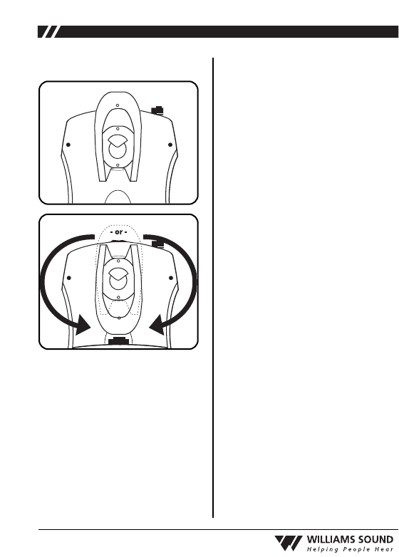
BELT CLIP INSTALLATION
To Install: Position the belt clip on
the rear of the T36 transmitter as
shown in FIG. E. Turn the belt clip
180˚ left or right as shown in FIG. F.
The belt clip is now installed and
ready for use.
To Remove: Turn the belt clip 180˚
so the open end of the clip points to
the top of the unit as shown in FIG.
E. Gently pull the belt clip away from
the unit to remove.
LIMITED WARRANTY
Williams Sound products are engi-
neered, designed and manufactured
under carefully controlled conditions
to provide you with many years of
reliable service. Williams Sound war-
rants the T36 transmitter against
defects in materials and workmanship
for FIVE (5) years. During the first
three years from the purchase date, we
will promptly repair or replace the
T36 transmitter.
Earphones, headphones, batteries,
cables, carry cases, and all other acces-
sory products carry a 90-day warranty.
Chargers carry a one year warranty.
WILLIAMS SOUND HAS NO CON-
TROL OVER THE CONDITIONS
UNDER WHICH THIS PRODUCT IS
USED. WILLIAMS SOUND,
THEREFORE, DISCLAIMS ALL
WARRANTIES NOT SET FORTH
ABOVE, BOTH EXPRESS AND
IMPLIED, WITH RESPECT TO THE
T36 TRANSMITTER, INCLUDING
BUT NOT LIMITED TO, ANY
IMPLIED WARRANTY OF MER-
CHANTABILITY OR FITNESS FOR
A PARTICULAR PURPOSE.
WILLIAMS SOUND SHALL NOT
BE LIABLE TO ANY PERSON OR
ENTITY FOR ANY MEDICAL
EXPENSES OR ANY DIRECT, INCI-
DENTAL OR CONSEQUENTIAL
DAMAGES CAUSED BY ANY USE,
DEFECT, FAILURE OR MALFUNC-
TION OF THE PRODUCT,
WHETHER A CLAIM FOR
FIG. E
FIG. F

6
®
SUCH DAMAGES IS BASED UPON
WARRANTY, CONTRACT, TORT OR
OTHERWISE. THE SOLE REMEDY
FOR ANY DEFECT, FAILURE OR
MALFUNCTION OF THE PRODUCT
IS REPLACEMENT OF THE PROD-
UCT. NO PERSON HAS ANY
AUTHORITY TO BIND WILLIAMS
SOUND TO ANY REPRESENTATION
OR WARRANTY WITH RESPECT TO
THE T36 TRANSMITTER. UNAU-
THORIZED REPAIRS OR MODIFI-
CATIONS WILL VOID THE WAR-
RANTY.
The exclusions and limitations set out
above are not intended to, and should
not be construed so as to contravene
mandatory provisions of applicable
law. If any part or term of this
Disclaimer of Warranty is held to be
illegal, unenforceable or in conflict
with applicable law by a court of com-
petent jurisdiction, the validity of the
remaining portions of this Disclaimer
of Warranty shall not be affected, and
all rights and obligations shall be con-
strued and enforced as if this Limited
Warranty did not contain the particular
part or term held to be invalid.
NOTE: THE MANUFACTURER IS
NOT RESPONSIBLE FOR ANY RADIO
OR TV INTERFERENCE CAUSED BY
UNAUTHORIZED MODIFICATIONS
TO THIS EQUIPMENT.
SUCH MODIFICATIONS COULD VOID
THE USER'S AUTHORITY TO
OPERATE THE EQUIPMENT.
If you experience difficulty with your
system, call Toll-Free for Customer
Assistance:
1-800-843-3544 (U.S.A.) or
+1 952 943 2252 (Outside the U.S.A.)
If it is necessary to return the system for
service, your Customer Service
Representative will give you a Return
Authorization Number (RA) and shipping
instructions.
Pack the system carefully and send it to:
Williams Sound Corp.
Attn: Repair Dept.
10321 West 70th Street
Eden Prairie, MN 55344