Wilson Electronics 271247SB Signal Boost DT Wireless Amplifier User Manual AIGR 801247 007 07 11 07 indd
Wilson Electronics, LLC Signal Boost DT Wireless Amplifier AIGR 801247 007 07 11 07 indd
USERS MANUAL
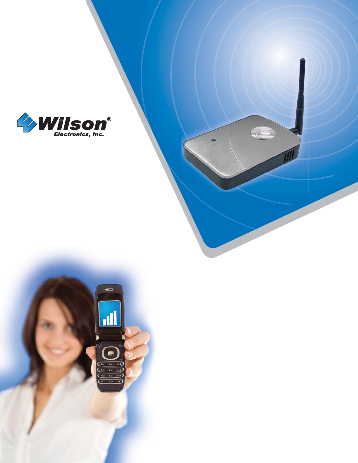
SIGNALBOOST™ DT
Dual-Band
Cellular/PCS
Amplifi er System
Installation Guide
Contents:
Guarantee and Warranty · · · · · · · · · · · · · · 1
Package Contents · · · · · · · · · · · · · · · · · · · 2
Tools Required for Installation · · · · · · · · · · 2
How It Works · · · · · · · · · · · · · · · · · · · · · · · 3
Before Getting Started · · · · · · · · · · · · · · · · 4
Reasons for Weak Cellular Signals · · · · · · 4
How to Check Your Outside Signal Strength 4
Installing the Cradle Antenna · · · · · · · · · · · 5
Installing the Amplifi er Unit · · · · · · · · · · · · · 9
Powering Up the Amplifi er · · · · · · · · · · · · · 10
Understanding the Indicator Light · · · · · · · 10
Warnings and Recommendations · · · · · · · 11
Frequently Asked Questions · · · · · · · · · · · 11
About Wilson Electronics · · · · · · · · · · · · · · 12
Amplifi er Specifi cations · · · · · · · Back Cover
SIGNALBOOST
DT
™
DESKTOP
T
D
D
D
D
D
D
D
D
D
D
D

SIGNALBOOST™ DT Installation Instructions
1
30-Day Money-Back Guarantee
All Wilson Electronics products are protected by Wilson’s 30-day money-back guarantee. If
for any reason the performance of any product is not acceptable, simply return the product
directly to the reseller with a dated proof of purchase.
1-Year Warranty
Wilson Electronics amplifi ers are warranted for one (1) year against defects in workmanship
and/or materials. Warranty cases may be resolved by returning the product directly to the
reseller with a dated proof of purchase.
Amplifi ers may also be returned directly to the manufacturer at the consumer’s expense, with
a dated proof of purchase and a Returned Material Authorization (RMA) number supplied by
Wilson Electronics. Wilson shall, at its option, either repair or replace the product. Wilson
Electronics will pay for delivery of the repaired or replaced product back to the original
consumer.
This warranty does not apply to any amplifi ers determined by Wilson Electronics to have
been subjected to misuse, abuse, neglect, or mishandling that alters or damages physical or
electronic properties.
RMA numbers may be obtained by phoning Technical Support at 866-294-1660.
Disclaimer: The information provided by Wilson Electronics, Inc. is believed to be complete
and accurate. However, no responsibility is assumed by Wilson Electronics, Inc. for any
business or personal losses arising from its use, or for any infringements of patents or other
rights of third parties that may result from its use.
Operation is subject to the following two conditions: (1) This device may not cause interference, and
(2) this device must accept any interference, including interference that may cause undesired operation of
this device.
Copyright © 2007 Wilson Electronics, Inc. All rights reserved.
Installation Instructions for the Following Wilson Amplifi er:
SIGNALBOOST™ DT Dual-Band Cellular/PCS Amplifer
Model # 271247, Part # 801247
FCC ID: PWO271247SB IC: 4726A-271247SB
The term “IC” before the radio certifi cation number only signifi es that Industry Canada technical
specifi cations were met.

SIGNALBOOST™ DT Installation Instructions 2
Welcome to the Wilson Electronics Family of Products!
Thank you for purchasing the Wilson SIGNALBOOST™ DT amplifi er system. You are just minutes away
from enjoying improved performance from your cellular phone and/or laptop data card. When installed
properly, the SIGNALBOOST™ DT will signifi cantly reduce dropped calls and improve both voice and
data signal quality. By taking a few minutes to read and follow the simple instructions in this guide, you
will get the most out of your new amplifi er system. If you have questions during or after installation, please
don’t hesitate to contact a member of our Technical Support team by phone (866-294-1660 or 435-673-
5021) or email (tech@wilsonelectronics.com). We’re here to help!
Inside this Package:
SIGNALBOOST™
DT Amplifi er On-board
Antenna Antenna
and Cradle AC Power
Supply Coaxial Cable
(50 ft.)
Amplifi er
Wall Bracket Window-Mount
(Packet A) Wall-Mount
(Packet B) Pole-Mount
(Packet C)
Tools Required for Installation:
Depending on your particular installation, you will need the following tools:
• Window-mount - No additional tools needed
• Wall-mount - Drill and 3/16-inch bit, Phillips-head screwdriver
• Pole-mount - 1/4-inch open-end wrench or adjustable wrench
SIGNALBOOST™ DT Installation Instructions
3
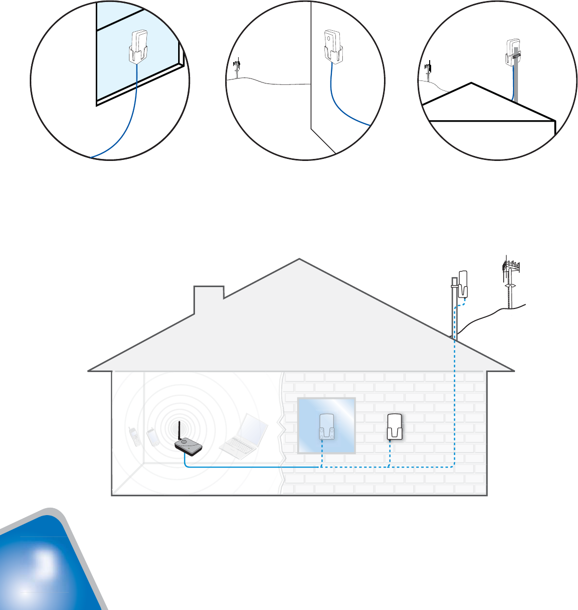
How it Works
Your new Wilson SIGNALBOOST™ DT amplifi er system has been carefully engineered to enhance the
performance of your cell phone or cellular data card. Its advanced technology is designed to signifi cantly
improve voice and data signal quality and reduce disconnects and drop-outs.
The SIGNALBOOST™ DT works with two antennas (included). The on-board antenna communicates
with your cell phone or laptop data card, and the cradle antenna communicates with the cell tower. the
cradle antenna is designed for installation inside on a window or outside on a wall or a pole, depending on
your preferred confi guration.
The cradle antenna collects the the outside signal and sends it through a cable to the SIGNALBOOST™
DT. The signal is then boosted and sent to the on-board antenna, which communicates with your cell
phone or data card. When the cell phone or data card transmits, the on-board antenna picks up the
signal and sends it to the amplifi er where it is boosted and sent through the cradle antenna to the cell
tower.
Note: While the SIGNALBOOST™ DT is designed to give you reliable signal improvement
with the included antennas, Wilson offers a variety of optional antennas and accessories that
enable you to customize your SIGNALBOOST™ DT to your specifi c needs.
Visit www.wilsonelectronics.com for details.
Window Installation (A) Wall Installation (B) Pole Installation (C)
Antenna
Option A (indoor)
Cradle Window Mount
Antenna
Option B (outdoor)
Cradle Wall Mount
Antenna
Option C (outdoor)
Cradle Pole Mount
Wireless
Amplifier
Area Needing
Increased
Signal
Cell
Tower
Antenna
and
Cradle
Cell
Tower
Antenna
and
Cradle
Antenna
and
Cradle
Cell
Tower

SIGNALBOOST™ DT Installation Instructions 4
Before Getting Started
This guide will help you properly install Wilson’s SIGNALBOOST™ DT. It is recommended that you
read through all of the installation steps and familiarize yourself with the product. Read the
instructions and visualize where you want to place the components before mounting any equipment. If
you do not understand the instructions in full, please contact Wilson Technical Support at 866-294-1660.
Reasons for Weak Cellular Signals
Anyone who uses a cell phone or cellular data card knows the frustration of not being able to connect to
or maintain a strong cellular signal. When this occurs, it’s generally due to one of two reasons:
1. Location of the Nearest Cell Tower – Cell towers are situated to provide broad coverage; however,
there are many areas in which signal strength may be reduced by topographic features or by local
government restrictions on the height or placement of the towers themselves. Rural areas generally
have fewer cell towers than urban regions.
2. Natural and Man-made Obstructions – Signal strength can also be negatively affected by trees, hills,
buildings and other obstructions. You may be relatively close to a cell tower but still unable to make a
call. This often occurs in homes, offi ces and other buildings in which stucco, concrete or metal walls
block the signal.
Whether you’re too far from the nearest cell tower to obtain a usable signal or you’re located in an area or
building where the signal is obstructed, the Wilson SIGNALBOOST™ DT can help you get connected and
stay connected!
How to Check Your Outside Signal Strength
Before you install your SIGNALBOOST™ DT, it is very important that you determine the location of the
best available cellular signal outside your building. This will affect where you place the cradle antenna and
will help you get the best performance from your system.
Your cell phone can help you fi nd the strongest outside signal, using any or all of the following methods:
1. Place calls from several locations outside your building and note where you get the best reception.
2. Check the bar indicator on your cell phone display and note where the signal appears to be the
strongest. (Note: cell phone bars are only an approximation of signal strength and vary from phone to
phone.)
3. Using the test mode on your cell phone, move around the outside of your building and determine the
location of the strongest signal. (For assistance with the test mode on your particular phone, visit the
Technical Support section of our website: www.wilsonelectronics.com or call our Technical Support
Department at 866-294-1660 or 435-673-5021.)
Once you have determined where the outside signal is strongest, you should plan to install the cradle
antenna in that general area, either inside or outside. (See the following section for alternative
installation options.)
SIGNALBOOST™ DT Installation Instructions
5
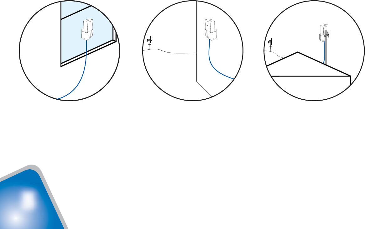
Installation Options - Cradle Antenna
The SIGNALBOOST™ DT comes with all necessary parts for installation of the cradle antenna in three
alternative locations:
• Inside on a window (suction cups or double-sided adhesive strip)
• Outside on a wall (screws, washers and anchors)
• Outside on a pole (bracket, nuts and washers)
The best location for your particular application depends primarily on outside signal strength (see page 4).
For example, if your strongest signal is obtained on the north side of the building and a suitable window
exists in that area, you may want to mount the cradle antenna inside on the glass (see page 6). If you fi nd
the strongest signal in an area with no window, an outside wall mount may be a better choice (see page
7). Or, if your particular application allows for the installation of the antenna on a roof or balcony to obtain
the strongest signal, mounting the cradle outside on a pole (not included) may be your best option (see
page 8).
IMPORTANT! Depending on your particular installation, the antenna must be positioned in the cradle
correctly. The side with the Wilson label should face in the direction of the cell tower.
Note: The amplifi er itself is designed to sit on a desk, table or shelf; however, it may also be mounted on
a wall with the included triangular bracket if you so desire (see page 9).
In all cases, you will want to insure a separation of at least 20 feet between the cradle antenna and the
amplifi er. The SIGNALBOOST™ DT comes with 50 feet of low-loss coaxial cable. Additional lengths of
cable and the necessary connectors are available through your Wilson dealer, but keep in mind that using
longer cable will result in some signal loss.
Window Installation (A) Wall Installation (B) Pole Installation (C)
Antenna
and
Cradle
Cell
Tower
Antenna
and
Cradle
Antenna
and
Cradle
Cell
Tower
SIGNALBOOST™ DT Installation Instructions 6
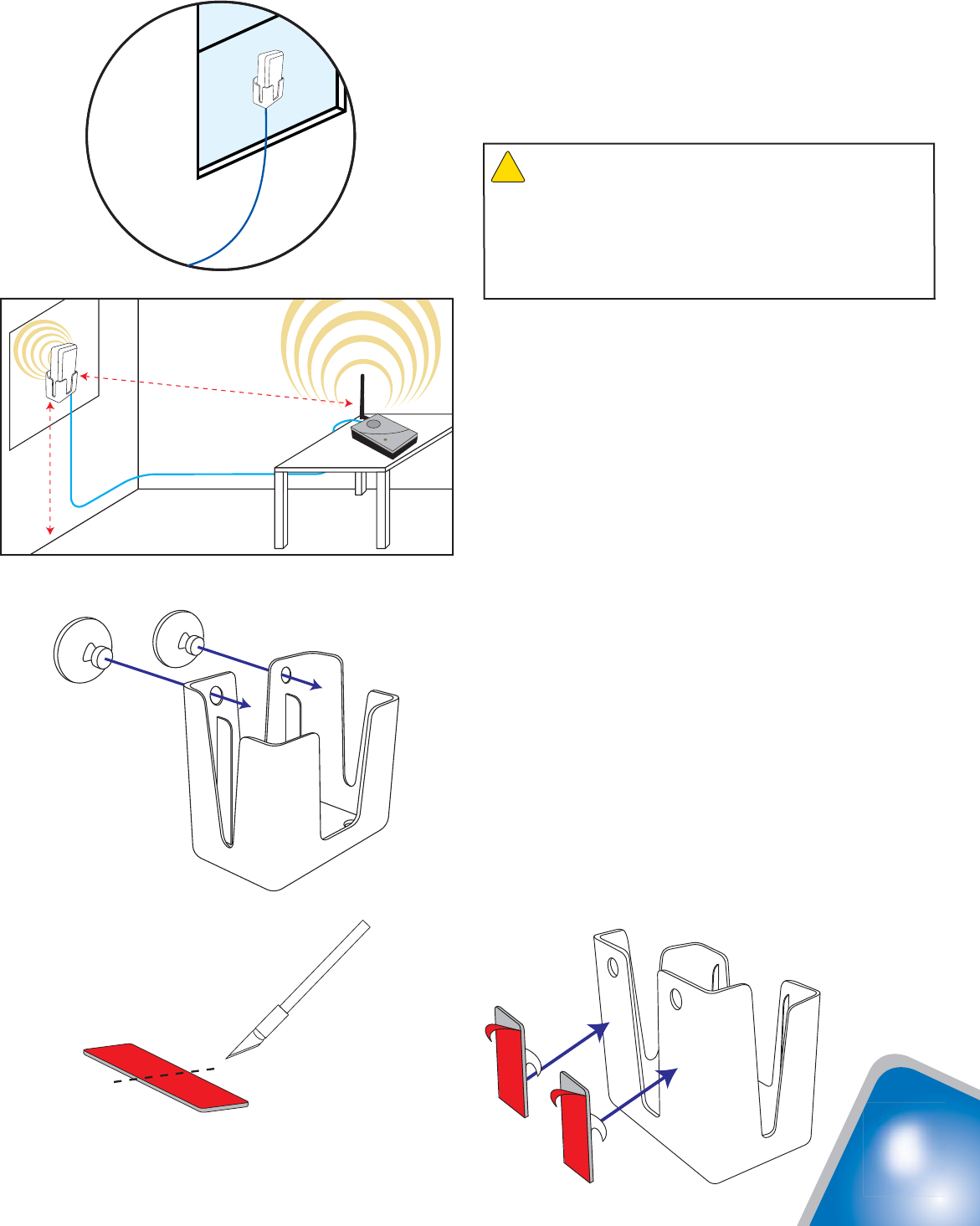
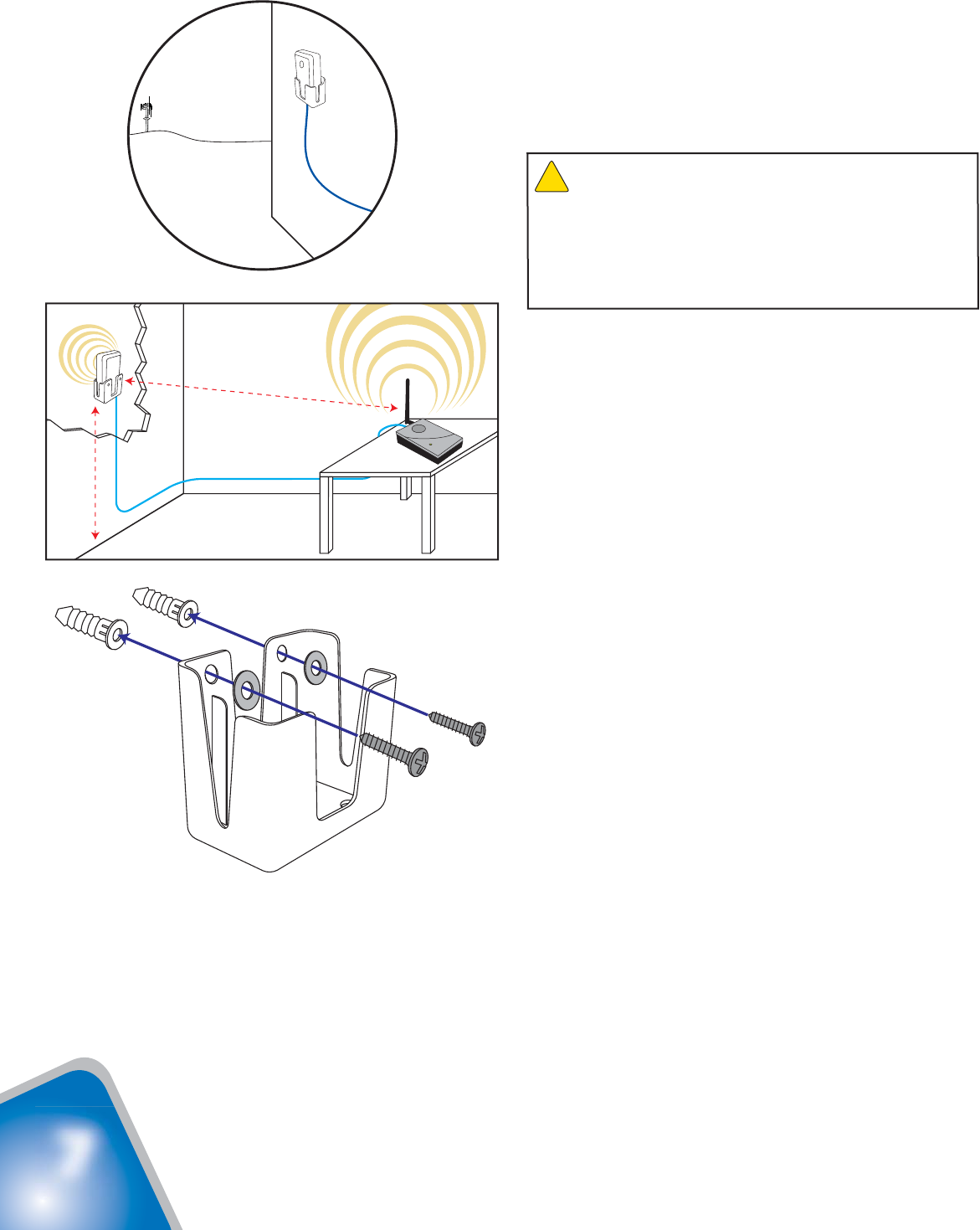
Installing the Cradle Antenna
Window Mount (Packet A)
1. Select a location on the inside of the window
at least 5 feet up from the fl oor, at least 20 feet
away from any other amplifi er or antenna and
at least 20 feet from where the amplifi er will be
located (see Figure 1).
2. Clean the area on the glass with the supplied
alcohol prep pad.
3a. If you plan to remove or relocate the cradle
antenna at some point, use the suction cups
provided in Packet A. Using a twisting motion,
press the suction cups into the two holes
on the antenna cradle (see Figure 2), then
press the cradle onto the glass at the desired
location.
3b. For a more permanant installation, use the
double-sided adhesive strip. Cut the strip as
shown in Figure 3. Peel the backing from one
side of the strip and place it on the back of the
cradle (see Figure 4). Peel the backing from
the other side of the strip and press the cradle
onto the glass at the desired location.
4. Insert the antenna into the cradle with the
Wilson label facing in the direction of the
cell tower. The cable connection should
protrude through the bottom of the cradle.
5. Connect one end of the supplied coax cable to
the antenna and route the cable as desired to
where the amplifi er will be located.
Min. 20 feet
Min. 5 feet
Figure 1
Suction cup installation
Figure 2
Adhesive installation
Figure 4
Figure 3
Antenna
and
Cradle
Warning: RF Safety: The cradle antenna, when used
with the included cable, must have a separation distance of at
least 8 inches from all persons. If the cable is shortened, or if a
different type of cable is used, or if a different antenna is used,
consult with Wilson Technical Support to verify that the planned
installation is safe. Call 866-294-1660 or 453-673-5021, or
email tech@wilsonelectronics.com.
!
SIGNALBOOST™ DT Installation Instructions
7
Wall Mount (Packet B)
1. Select a location on an outside wall at least 5
feet up from the ground, at least 20 feet away
from any other amplifi er or antenna and at least
20 feet away from where the amplifi er will be
located (see Figure 5).
2. Using the cradle as a template, position it on
the wall in the desired location and mark the
screw holes with a pencil.
3. Drill two holes where marked, using a 3/16-inch
bit, and insert the screw anchors.
4. Line up the holes in the cradle with the screw
anchors and mount the cradle to the wall using
two screws and two washers (see Figure
6). Tighten the screws with a Phillips-head
screwdriver.
5. Insert the antenna into the cradle with the
Wilson label facing in the direction of the
cell tower. The cable connection should
protrude through the bottom of the cradle.
6. Connect one end of the supplied coax cable to
the antenna and route the cable as desired to
where the amplifi er will be located.
Min. 20 feet
Min. 5 feet
Figure 5
Figure 6
Antenna
and
Cradle
Cell
Tower
Warning: RF Safety: The cradle antenna, when used
with the included cable, must have a separation distance of at
least 8 inches from all persons. If the cable is shortened, or if a
different type of cable is used, or if a different antenna is used,
consult with Wilson Technical Support to verify that the planned
installation is safe. Call 866-294-1660 or 453-673-5021, or
email tech@wilsonelectronics.com.
!
SIGNALBOOST™ DT Installation Instructions 8
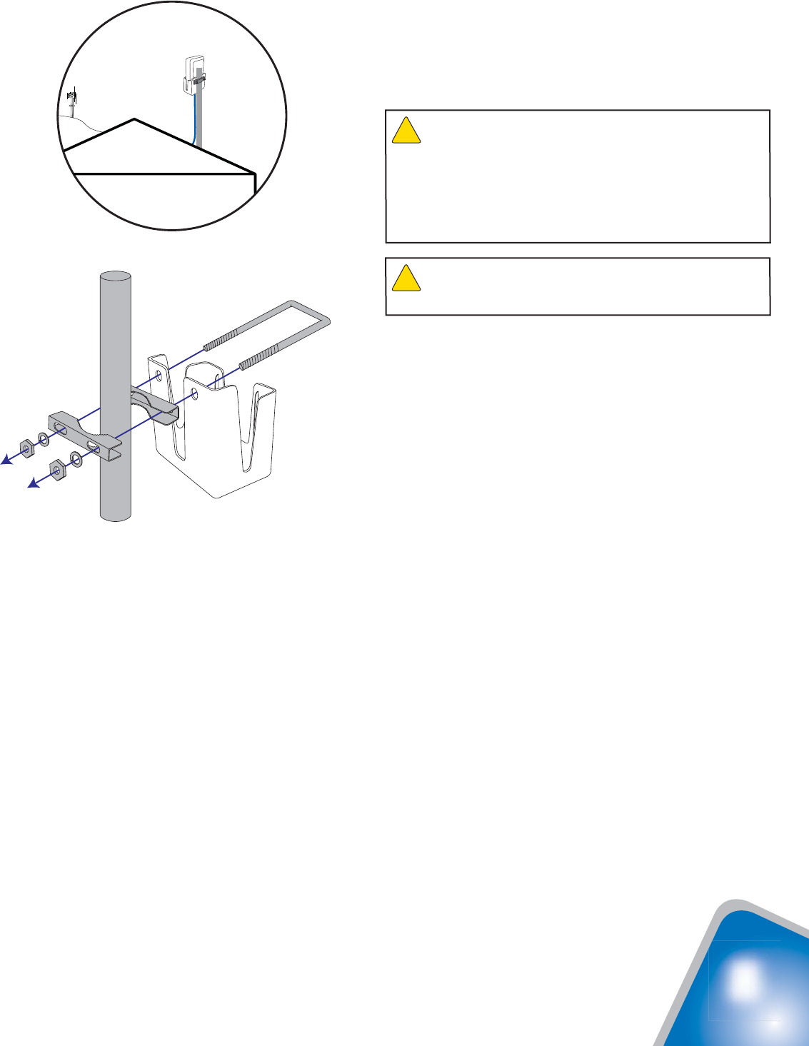
Pole Mount (Packet C)
1. The supplied pole-mount bracket is designed to
accomodate a pole diameter of 1 to 2 inches.
Install the pole in the desired location using
your own hardware.
2. Insert the supplied U-bolt through the holes
in the cradle and slide one half of the bracket
assembly onto the U-bolt (see Figure 7).
3. Fitting the assembly onto the pole, slide the
second half of the bracket onto the U-bolt and
secure it with lock washers and nuts. Be sure
the cradle is at the desired height on the pole
and is rotated toward the nearest cell tower
before tightening the nuts.
4. Insert the antenna into the cradle with the
Wilson label facing in the direction of the
cell tower. The cable connection should
protrude through the bottom of the cradle.
5. Connect one end of the supplied coax cable to
the antenna and route the cable as desired to
where the amplifi er will be located.
Figure 7
Cell
Tower
Antenna
and
Cradle
Warning: Take care to ensure that neither you nor the
pole comes near any power lines during installation.
!
Warning: RF Safety: The cradle antenna, when used
with the included cable, must have a separation distance of at
least 8 inches from all persons. If the cable is shortened, or if a
different type of cable is used, or if a different antenna is used,
consult with Wilson Technical Support to verify that the planned
installation is safe. Call 866-294-1660 or 453-673-5021, or
email tech@wilsonelectronics.com.
!

SIGNALBOOST™ DT Installation Instructions
9
Installing the Amplifi er Unit
Desk or Table Mount
1. Attach the on-board antenna by screwing it
onto the threaded connector on the amplifi er.
Position the antenna vertically by rotating it on
its base (see Figure 8). Operating the amplifi er
with the on-board antenna in a position other
than vertical will reduce its performance.
2. Place the amplifi er on a desk, table or similar
surface where you have routed the coax cable.
3. Attach the cable to the connector on the
amplifi er.
Wall Mount
1. Attach the on-board antenna by screwing it
onto the threaded connector on the amplifi er
(see Figure 8).
2. Position the triangular wall-mount bracket at the
desired spot on the wall, at least 5 feet up from
the fl oor and away from any other amplifi er or
antenna.
3. Using the bracket as a template, mark the
locations for the screws using a pencil.
4. Drill the holes, using a 3/16-inch drill bit, and
insert the screw anchors. Note: if you are not
using the wall-mount hardware in Packet B
for the cradle antenna, you can use it for the
amplifi er. Otherwise, you will need to purchase
three screws, washers and anchors.
5. Align the triangular bracket with the screw
anchors (Figure 9) and attach it with screws
and washers. Tighten the screws with a
Phillips-head screwdriver.
6. Slide the amplifi er onto the bracket. Position
the antenna vertically for best performance
(see Figure 10). Operating the amplifi er with
the on-board antenna in a position other than
vertical will reduce its performance.
7. Attach the cable to the connector on the
amplifi er.
Warning: The on-board antenna must have a separation
distance from all persons that is at least 8 inches.
!
Warning: Connecting the amplifi er
directly to the cell phone with use of an
adapter will damage the cell phone.
!
Figure 9
Min. 20 feet
Min. 5 feet
Figure 10
Figure 8
Warning: RF Safety: The amplifi er must be placed so that
its on-board antenna has a separation distance of at least 8
inches from all persons.
!
Warning: The amplifi er unit is designed for use in an
indoor, temperature-controlled environment. It is not intended
for use in attics or similar locations subject to temperatures in
excess of 120 degrees Fahrenheit.
!
Warning: RF Safety: The amplifi er must be placed so that
its on-board antenna has a separation distance of at least 8
inches from all persons.
!
SIGNALBOOST™ DT Installation Instructions 10
Powering Up the Amplifi er
1. Ensure that the distance between the amplifi er
and the cell phone or cellular data card does
not exceed 4 feet.
2. Important: Ensure that any other cell phones
and cellular data cards are turned off unless
they are at least twice the distance from the
amplifi er than the desired unit.
3. Ensure that the distance between the on-board
antenna and the cradle antenna is a minimum
of 20 feet. If you are using a different antenna
confi guration, see the separation guidelines
for your specifi c antennas or call Wilson’s
Technical Support department at 866-294-1660
or 435-673-5021.
4. Ensure that the coax cable is attached to
the amplifi er and the cradle antenna before
powering up the amplifi er.
5. Plug the power supply into the amplifi er input
marked “Power” (carefully, to avoid damaging
the center pin) and then into a wall outlet.
Understanding the Indicator Light
The indicator light on the top of the amplifi er will be
GREEN when the unit is powered up and working
properly.
If the indicator light is AMBER, this indicates that
the cell phone or data card may be too close to
the amplifi er and the amplifi er has automatically
reduced its gain. Move farther from the amplifi er
when making a call so that the light is green.
If the indicator light is RED, the amplifi er has
detected oscillation. Increase the separation
between the on-board antenna and the cradle
antenna (or whatever two antennas you may be
using). Remove and reinsert the power cable to
reset the amplifi er. If the light remains red,
repeat the antenna separation/power
reset procedure until the light is green.
Warning: Use only the power supply provided in this
package. Use of a non-Wilson product may damage your
equipment.
!
Warning: Verify that the on-board antenna is attached
and that the cable from the cradle antenna is connected before
powering up the amplifi er.
!
Min. 20 feet
GREEN:
AMBER:
RED:
SIGNALBOOST™ DT Installation Instructions
11
Warnings and Recommendations
Warning: Connecting the amplifi er directly to the cell phone with use of an adapter will damage the
cell phone.
Warning: Attach the on-board antenna and connect the cradle antenna before powering up the
amplifi er.
Warning: Use only the power supply provided in this package. Use of a non-Wilson product may
damage your equipment.
Warning: RF Safety: A minimum separation distance of at least 8 inches must be maintained
between the antennas supplied with this amplifi er and all persons. A different antenna
may be used in place of the on-board antenna, provided that its gain does not exceed
15 dBi and it is separated by at least 8 inches form all persons. Antennas outside of
the building may have gains as high as 15 dBi, provided that a separation distance of
at least 30 inches is maintained between the antennas and all persons. Use of antennas
with higher than the above maximum gains and/or closer to people than the specifi ed
minimum distance is in violation of FCC regulations for which the offender is fully liable.
Frequently Asked Questions
What kind of improvement in cell phone performance can I expect with the SIGNALBOOST™ DT?
The SIGNALBOOST™ DT’s performance will depend somewhat on the strength of the cellular signal
outside your home or building. However, if you install the SIGNALBOOST™ DT in accordance with the
instructions in this guide, you can expect a signifi cant improvement in your ability to use your cell phone
or cellular data card indoors.
Where should I install my SIGNALBOOST™ DT to get the best coverage?
You should install the amplifi er in the area where you most need an improved signal. The farther you
are from the amplifi er, the less improvement you will experience. It is also important to install the cradle
antenna in a location where you have the strongest outside signal (see page 4). Also keep in mind the
distance between the amplifi er and the cradle antenna. You’ll need at least 20 feet of separation to
prevent the start of oscillation, but you’ll probably want to stay within the 50-foot length of the coax cable.
(Additional cable and the necessary connectors are available from your Wilson dealer, but using more
cable will result in some signal loss.)
Instead of placing the amplifi er on a desk or table, I’d rather attach it to a wall – will it still work OK?
Yes! Your SIGNALBOOST™ DT comes with a triangular wall bracket that allows you to mount the
amplifi er on a wall. Just be sure that the on-board antenna is positioned vertically and not at a right angle
to the wall (see page 9).
What color should the indicator light be showing?
Once the amplifi er is powered up, the indicator light should be green during normal operation.
The amplifi er indicator light is amber – what does that mean?
An amber light indicates that the amplifi er has reduced its gain because the cell phone or data card is too
close to it. Move farther away from the amplifi er when making a call or using your data card.
The amplifi er light is red – what does that mean?
A red light indicates oscillation between the on-board antenna and the cradle antenna. Increase
the separation between the amplifi er and the cradle antenna, then remove and reinsert the power
cable to reset the amplifi er. If the light remains red, repeat this procedure until the light is green.
!
!
!
!

SIGNALBOOST™ DT Installation Instructions 12
I have a Nextel phone – will the SIGNALBOOST™ DT boost that signal?
The SIGNALBOOST™ DT is designed to work with both the Cellular (800 MHz) and PCS (1900 MHz)
bands, but not the iDEN/Nextel frequency. Wilson offers specifi c amplifi ers for iDEN/Nextel users. Visit
www.wilsonelectronics.com for details.
Can I use my own cable for my installation?
The low-loss RG6 cable included with your product has been specifi cally selected for the
SIGNALBOOST™ DT. Use of another type or longer length of cable will likely degrade the system’s
performance.
There are frequently several people using cell phones in my building at the same time – will the
SIGNALBOOST™ DT improve the signal for all of them?
Absolutely! The SIGNALBOOST™ DT is designed to support multiple users simultaneously.
I have questions about my installation – where can I get some help?
Wilson’s Technical Support representatives are just a phone call or email away. Call 866-294-1660 or
435-673-5021, or send an email to tech@wilsonelectronics.com.
About Wilson Electronics
Wilson Electronics, Inc. a leader in the wireless communications industry for over 40 years, designs and
manufactures amplifi ers, antennas and related components that signifi cantly improve cellular telephone
signal reception and transmission in a variety of applications, both mobile and in-building.
With extensive experience in antenna and amplifi er research and design, the company’s engineering
team uses a state-of-the-art testing laboratory, including an anechoic chamber and network analyzers,
to fi ne-tune antenna designs and performance. For its amplifi ers, Wilson uses a double electrically
insulated RF enclosure and cell site simulators for compliance testing.
Wilson amplifi ers feature patent-pending Smart Technology™ that enables them to automatically adjust
their power based on cell site requirements. By detecting and preventing oscillation, signal overload and
interference with other users, these Smart Technology™ amplifi ers improve network cell phone areas
without compromising the carrier’s system.
All products are engineered and assembled in the company’s 50,000-square-foot headquarters in St.
George, Utah. Wilson has product dealers in all 50 states and in countries around the world.

Part #104027 AIGR SBDT 007 - 07.11.07
Amplifi er Specifi cations
Dual-Band Wireless
800/1900 MHz Specifi cations
Model Number 271247
Connectors To onboard antenna: TNC Female To cradle antenna: F Female
Impedance Onboard antenna: 50 ohms Cradle antenna: 75 ohms
Dimensions 6.2 x 4.2 x 1.5 inch (15.7 x 10.7 x 3.8 cm)
Weight 0.64 lbs (0.29 kg)
Frequency 824-894 MHz / 1850-1990 MHz
1Passband Gain (nominal)
800 MHz 55 dB Maximum
1900 MHz 55 dB Maximum
220 dB Bandwidth (nominal)
800 MHz 32 MHz
1900 MHz 74 MHz
Power output for single cell phone (uplink) 800 MHz 1900 MHz
CDMA 29.9 dBm 29.7 dBm
GSM 28.8 dBm 31.1 dBm
EDGE 30.8 dBm 31.1 dBm
AMPS 29.5 dBm
Power output for single received channel (downlink) 800 MHz 1900 MHz
CDMA 15.6 dBm 12.5 dBm
GSM 11.7 dBm 11.6 dBm
EDGE 12.4 dBm 9.5 dBm
AMPS 12.3 dBm
3Power output for multiple received channels (uplink) Maximum Power
The maximum power is reduced
by the number of channels: Number of
channels 800 MHz 1900 MHz
2 22.6 dBm 23.2 dBm
3 19.0 dBm 19.7 dBm
4 16.5 dBm 17.2 dBm
5 14.6 dBm 15.3 dBm
6 13.0 dBm 13.7 dBm
4Power output for multiple received channels (downlink) Maximum Power
The maximum power is reduced
by the number of channels: Number of
channels 800 MHz 1900 MHz
2 13.4 dBm 14.3 dBm
3 9.9 dBm 10.7 dBm
4 7.4 dBm 8.2 dBm
5 5.4 dBm 6.3 dBm
6 3.8 dBm 4.7 dBm
Noise Figure (typical) 3.5 dB nominal
Isolation (uplink/downlink) > 90 dB
Power Requirements 110-240 V AC, 50-60 Hz, 8 W
Notes:
1. Nominal gain is the maximum gain at any frequency in the passband.
2. Nominal bandwidth is the difference between two frequencies that are adjacent to the passband where the amplifi cation is 20 dB lower than the passband amplifi cation.
One of the frequencies is lower than the passband and the other is higher.
3. The Manufacturer’s rated output power of this equipment is for single carrier operation. For situations when multiple carrier signals are present, the rating would have
to be reduced by 3.5 dB, especially where the output signal is re-radiated and can cause interference to adjacent band users. This power reduction is to be by means
of input power or gain reduction and not by an attenuator at the output of the device.
4. The maximum power for 2 or more simultaneous signals will be reduced by 6 dB every time the number of signals is doubled.