Wilson Electronics 460001 Wideband Consumer Booster (CMRS) User Manual
Wilson Electronics, LLC Wideband Consumer Booster (CMRS) Users Manual
Contents
- 1. User Manual rev3
- 2. Users Manual
Users Manual
TM
Cellular Signal Booster
460101
Need help? www.WilsonElectronics.com Tech Support 866-294-1660
Mon.- Fri. Hours: 7 am to 6 pm MST
2Need help? www.WilsonElectronics.com Tech Support 866-294-1660
Mon.- Fri. Hours: 7 am to 6 pm MST
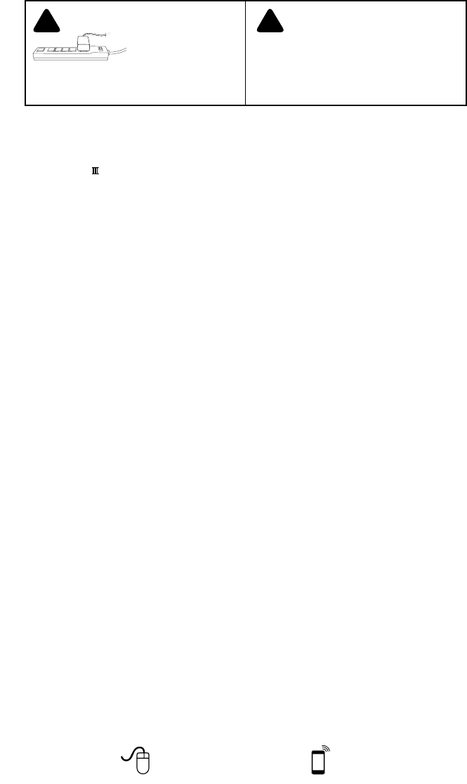
IT IS VERY IMPORTANT
TO POWER YOUR SIGNAL
BOOSTER USING A SURGE
PROTECTED AC POWER
STRIP WITH AT LEAST A 1000
JOULE RATING.
FAILURE TO DO THIS WILL VOID YOUR WARRANTY
IN THE EVENT OF A POWER SURGE OR LIGHTNING
STRIKE.
! ! THE SIGNAL BOOSTER UNIT IS DESIGNED
FOR USE IN AN INDOOR, TEMPERATURE-
CONTROLLED ENVIRONMENT (LESS
THAN 150 DEGREES FAHRENHEIT). IT IS
NOT INTENDED FOR USE IN ATTICS OR SIMILAR
LOCATIONS SUBJECT TO TEMPERATURES IN
EXCESS OF 150°F.
Contents
Package Contents ......................................................3
Optional Accessories ...................................................3
Before Getting Started ..................................................3
Find the Strongest Signal ................................................4
Quick Install - Inside Window Mount Option ................................5
Installation Options .....................................................6
Outside Pole Mount (Best Option) ......................................6
Outside Wall Mount Option ............................................7
Rafter Mount Option .................................................8
Additional Considerations ...............................................8
DT4G™ and Desktop Antenna Placement ..................................9
Troubleshooting & Understanding Lights ..................................10
Additional FAQ ........................................................12
Safety Guidelines & Recommendations ...................................14
Signal Booster Specifications ...........................................15
Guarantee and Warranty ........................................ Back Cover
Installation Instructions for the Following Wilson Electronics Signal Booster:
DT4G 700 MHz Band 13 & 17, 800 / 1900 (Ext. PCS) AWS (1700 / 2100)
SmartTech ™ Signal Booster
Model # 460001 FCC ID: PWO460001 IC: 4726A-460001
3
Need help? www.WilsonElectronics.com Tech Support 866-294-1660
Mon.- Fri. Hours: 7 am to 6 pm MST
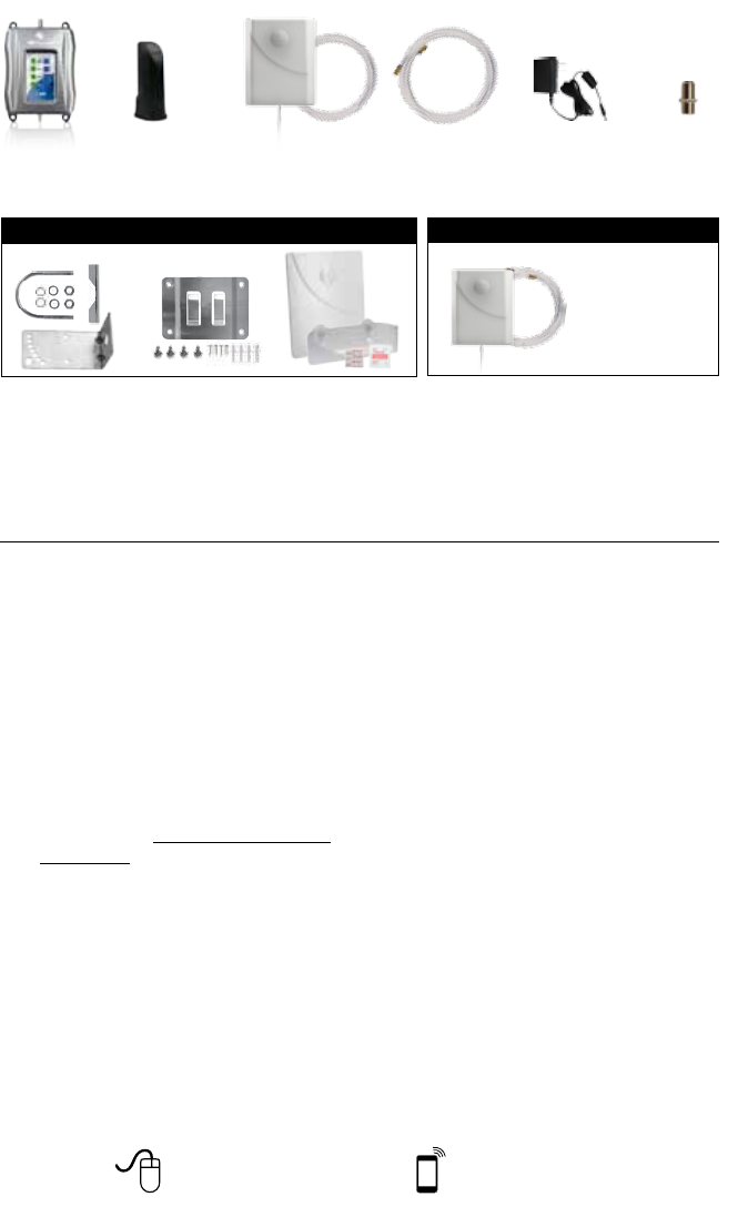
5V / 2.5A
(859948)
30’ RG6
Coax Cable
(950630)
Cable
Connector
(971129)
Desktop Antenna
(5’ RG-174 comes attached)
(301211)
Package Contents
Mounting Option Accessories (Included)
Outside Panel Antenna Kit
Outside Panel Antenna
30’ RG6 coax cables
(314473-0630)
DT4G
A B C
Before Getting Started
2. Watch the YouTube video
installation at:
DT4Gvideo.
3. Determine the best installation option
(Best Option)
– Rafter Mount
referenced in the instructions.
Panel Antenna
RG6 30’ Coax Cable
Required F-Female to SMA
Male adapter
DT4G Inside Panel Antenna Upgrade
(311155-0630)
Tools Required for Installation:

4Need help? www.WilsonElectronics.com Tech Support 866-294-1660
Mon.- Fri. Hours: 7 am to 6 pm MST
Find the Strongest Cellular Signal
1. Best method:
Connect the Outside Antenna to the
to the Desktop Antenna. Have one
person outside (on the roof for best
a. The person inside should have
the phone in test mode so the
read. This is more accurate than
the bar indicator. Go to
instructions
b. The person on the roof should turn
Rotate in 45°
increments
c. The person inside should note the
direction.
2. Good methods:
a. Place calls from several locations
to the App Store and search for
3. Acceptable method: Check the bar
phone.) Phones can take up to 30
several times.
installation video at:
DT4Gvideo.
WAIT 30
SECONDS

5
Need help? www.WilsonElectronics.com Tech Support 866-294-1660
Mon.- Fri. Hours: 7 am to 6 pm MST
4. Insert the Outside Antenna into the
cradle.
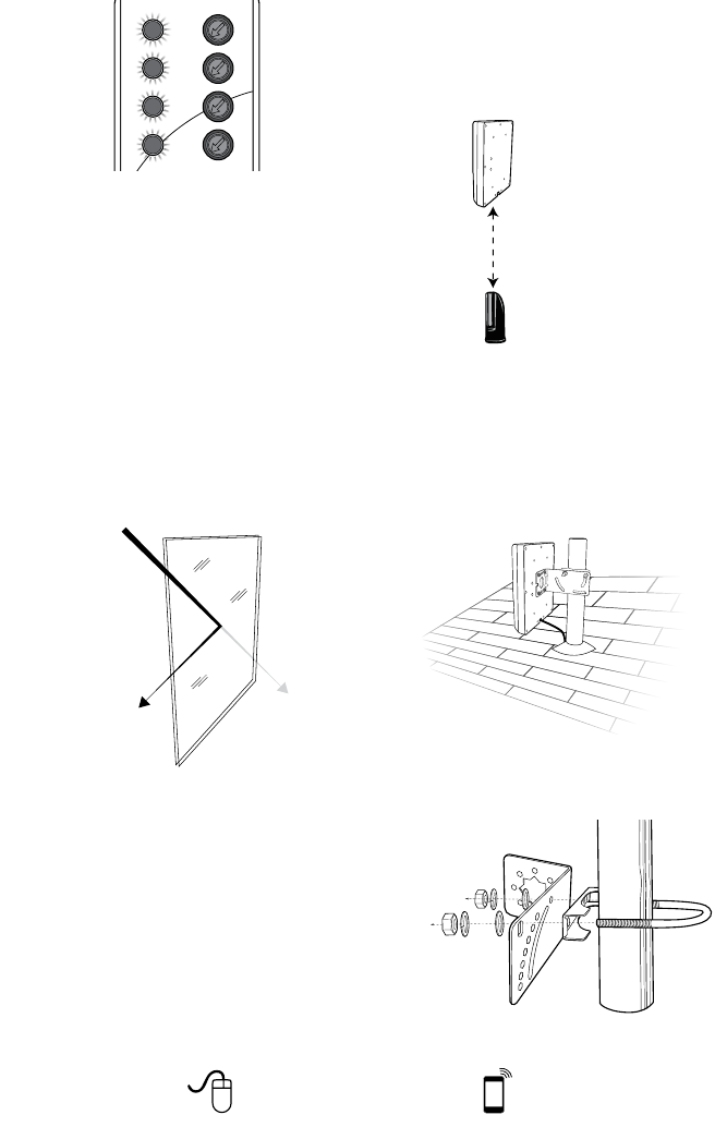
Window faces general
direction of cell tower
5. Connect the supplied coax cable to
the antenna lead cable on the Outside
Antenna.
6. Route the cable as desired to the
connect both coax cables, use the
Cable Connector provided.
7. Connect the coax cable to the DT4G.
Connect the Desktop Antenna to the
DT4G. For instructions on install and
Desktop Antenna placement refer to
Quick Install - Inside Window
Mount Option
Additional installation options on pg. 6-8
Find the Strongest Cellular Signal
Ready to Install
Inside Window Mount
1. Select a location on the inside of
mount to be in a different room from
Window faces general
direction of cell tower
alcohol prep pad included in Packet C.
3. Insert the suction cups included in
Packet C into the holes on the Outside
motion. Press the suction cups onto
twist through
twist through
6Need help? www.WilsonElectronics.com Tech Support 866-294-1660
Mon.- Fri. Hours: 7 am to 6 pm MST
NOTE:
pane windows with coatings will
weaken the cellular signals as
they pass through because of a
manufacturing. If you have dual-
coatings, we recommend one
of the other mounting options if
your performance is not to your
satisfaction.
Installation Options
Outside Pole Mount Option
(Best Option)
Outside Antenna can be mounted on
vertical or horizontal separation from the
inside Desktop Antenna.
pole of 1 to 2 inches in diameter.
to the roof can be purchased from a
part #901117. Install the pole in the
desired location.
Place the desktop signal
antenna directly beneath the
placement of the Outside
Antenna location
At least 20 feet of vertical
or horizontal separation
from the desktop antenna
is needed

7
Need help? www.WilsonElectronics.com Tech Support 866-294-1660
Mon.- Fri. Hours: 7 am to 6 pm MST
half of the bracket onto the U-bolt and
nuts provided. Be sure the cradle is at
5. Connect the supplied coax cable to
the antenna lead cable on the Outside
Antenna.
6. Route the cable as desired to the
connect both coax cables, use the Cable
Connector provided. Secure the cable
Outside Wall Mount Option
2. Position the Outside Antenna bracket,
Face in roughly the same
direction as the strongest
cellular signal
Outside
Antenna
bracket
4. Line up the Outside Antenna bracket
the cradle antenna bracket to the
wall
side view
anchors
anchors
5. Connect the supplied coax cable to
the antenna lead cable on the Outside
Antenna.
6. Route the cable as desired to the
connect both coax cables, use the
Cable Connector provided.
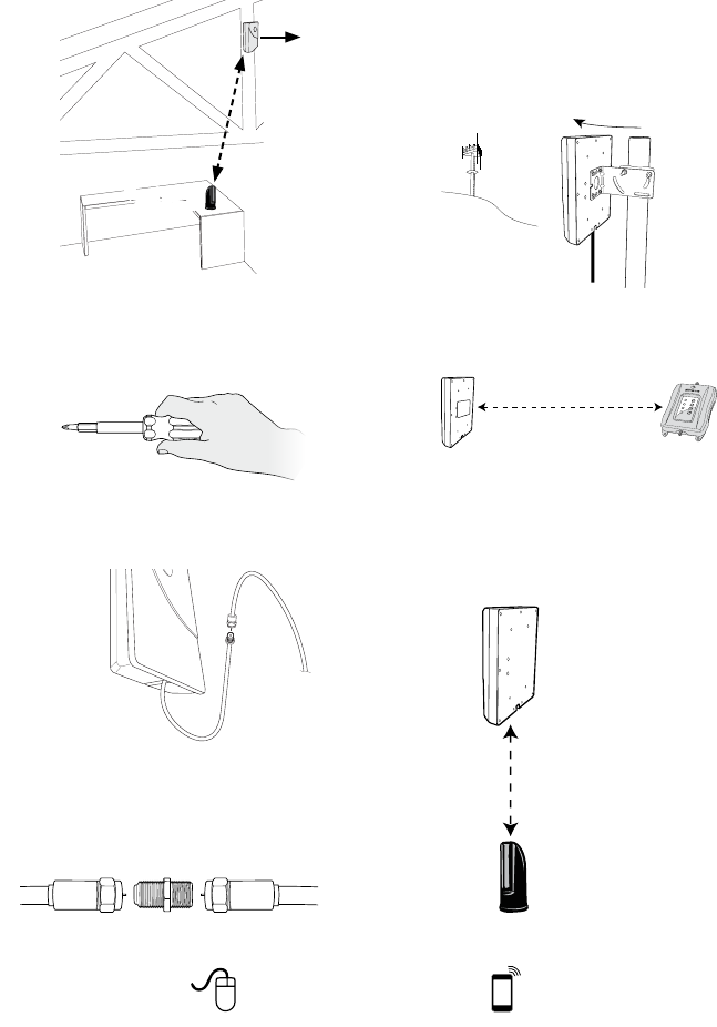
8Need help? www.WilsonElectronics.com Tech Support 866-294-1660
Mon.- Fri. Hours: 7 am to 6 pm MST
Rafter Mount Option
or horizontal separation. The location
2. Mount the Outside Antenna bracket
3. Connect the supplied coax cable to
the antenna lead cable on the Outside
Antenna.
4. Route the cable as desired to the
connect both coax cables, use the
Cable Connector provided.
Additional Considerations
at the Outside Antenna. Be sure to
Antenna.
Rotate in small
increments
2. Maintain a distance of at least 20 feet
from the Outside Antenna to the DT4G
unit.
If possible, place the Desktop
placement of the Outside Antenna
location. This creates a maximized
Desktop Antenna remains.
Mount in the general
direction of the strongest
cellular signal
Mount at least
20 feet apart
Minimum separation
of 20 feet
Place the desktop signal
antenna directly beneath the
placement of the Outside
Antenna location
At least 20 feet of vertical
or horizontal separation
from the desktop antenna
is needed

9
Need help? www.WilsonElectronics.com Tech Support 866-294-1660
Mon.- Fri. Hours: 7 am to 6 pm MST
3. Keep the DT4G and the Desktop
Antenna at least 18 inches away
from the DT4G.
4. Do not face the Outside Antenna and
other. This can cause the DT4G
on the Outside Antenna and the
Recommended: Lightning Surge
Protector (Sold Separately, part #859992)
DT4G. Attach the cable from the Outside
The LSP is
Ground
Wire
DO NOT
face the Outside Antenna and
the Desktop Antenna toward
each other
Minimum separation
of 18 inches
DT4G and Desktop Antenna
Placement
1. Select a location for the DT4G that
ventilation. Recommended locations
include on a shelf, in a closet, on a
desk or behind it. Be sure the location
proper ventilation, keep other objects
2. Place the DT4G on a desk, table or
routed the cable from the Outside
Antenna.
3. Attach the coax cable from the
Outside Antenna to the DT4G at the
connector labeled “Outside Antenna.”
4. Attach the Inside Antenna to the
connector labeled “Inside Antenna.”
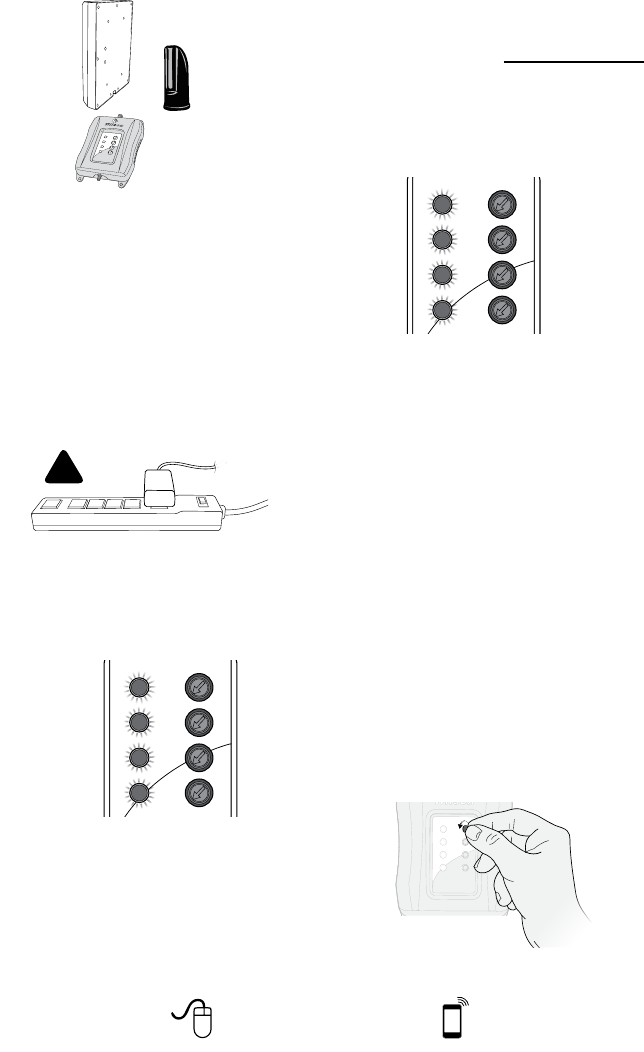
10 Need help? www.WilsonElectronics.com Tech Support 866-294-1660
Mon.- Fri. Hours: 7 am to 6 pm MST
Outside Antenna.
the “Outside Antenna” connector).
Important notice: Connect your DT4G
AC Power Supply to a surge protected
AC power strip with at least a 1000 Joule
rating. Failure to do this will void your
warranty in the event of a power surge or
lightning strike.
!
Note
Face Inside Antenna
away from DT and
Outside Antenna
Troubleshooting &
Understanding Lights
for each band (for more information about
service provider visit .)
or red.
Green
Red indicates the DT4G has shut
Orange indicates the DT4G is
overloaded because it is too close to
Note: All red light issues must be resolved
before orange light issues.
Fixing Red Light Issues
for the DT4G to reset. Continue this
Wait 5 seconds
between each
adjustment
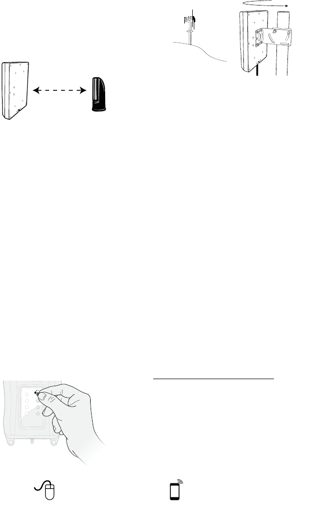
11
Need help? www.WilsonElectronics.com Tech Support 866-294-1660
Mon.- Fri. Hours: 7 am to 6 pm MST
IMPORTANT NOTE:
c) You need to increase the distance
Increase horizontal
and/or vertical
distance
the Wilson Electronics Technical
Support Team for assistance:
866-294-1660.
Fixing Orange Light Issues
.
Wait 5 seconds
between each
adjustment
the Outside Antenna. Continue to adjust
Electronics Technical Support Team for
assistance: 866-294-1660.
Lights Off
For additional descriptions on
.
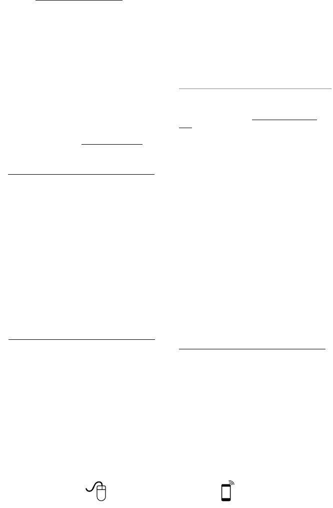
12 Need help? www.WilsonElectronics.com Tech Support 866-294-1660
Mon.- Fri. Hours: 7 am to 6 pm MST
Additional FAQ:
What hours can I contact tech support?
Technical Support can be reached from 7:00am
email, at .
How does weather affect the performance of
my Outside Antenna?
see less performance.
What’s the difference between the 800 MHz
and the 1900 MHz bands? How do I know
which MHz band my cell phone uses?
cellular providers on the 800 & 1900 MHz
For more detail, refer to .
Why do I need to maintain at least 20 feet of
separation, but no more than 50 feet? OR
Why do I need to create so much distance
between the antennas?
Antennas connected to a booster create a sphere
condition called oscillation occurs. This oscillation
United States Carrier Frequency Use
com
Kit 301121-40010
Kit 311135-40060
Kit 301151-0610
Kit 311135-5820
Kit 311135-40060
Kit 301151-1110
Kit 311155-1150
Kit CANT-0045
Kit CANT-0039
Kit YX-052
Kit 301211
50 Ohm Outside Antenna Kits
Kit 314453-5825
Kit 314411-5825
Kit 301111-5850
Kit 311129-5840
Kit 311203-5820
Inside Antenna Kits
Kit 309900-50N
Kit 309905-50N
Kit 309902-75F
Kit 309903-75F
Kit 309904-75F
Inside Antenna Expansion Kit
13
Need help? www.WilsonElectronics.com Tech Support 866-294-1660
Mon.- Fri. Hours: 7 am to 6 pm MST
Kit 311124-5830
Kit 311203-40020
Kit 301111-400170
Kit 311124-400100
Kit 311129-400100
Kit 314411-40075
Kit 314453-40075
75 Ohm Outside Antenna Kits
Kit 301111-0675
Kit 311201-0620
Kit 311129-0660
Kit 311129-0650
Kit 314473-0640
Kit 311141-0620
Kit 301111-11140
Kit 311201-1120
Kit 311129-11110
Kit 311124-1180
Kit 314473-1175
Kit 314475-0630
Kit 314475-1175
Kit 311141-1120
Kit CANT-0040
Kit CANT-0043
Kit CANT-0042
14 Need help? www.WilsonElectronics.com Tech Support 866-294-1660
Mon.- Fri. Hours: 7 am to 6 pm MST
Lightning
Surge Protector
To Outside
Antenna
To Signal Booster
Ground Wire
(not included)
!RECOMMENDED: INSTALLING THE LIGHTNING SURGE PROTECTOR
(SOLD SEPARATELY)
INSTALL THE LIGHTNING SURGE PROTECTOR (LSP) CLOSE TO THE SIGNAL
BOOSTER. ATTACH THE CABLE FROM THE OUTSIDE ANTENNA TO THE
SURGE PROTECTOR. ENSURE THE LSP IS PROPERLY GROUNDED.
#859992-75 OHM MAY BE PURCHASED AT WWW.WILSONELECTRONICS.COM
OR BY CALLING 800-204-4104.
Safety Guidelines
WARNING:
at least 6 feet of separation distance from Panel and Dome antennas and 4 feet of separation
distance from Desktop antennas.
WARNING:
cell phone.
WARNING:
WARNING:
WARNING:
WARNING:
RF SAFETY WARNING:
BEFORE USEMUST REGISTER THIS DEVICE
You MUST
the manufacturer. Antennas MUST
person.
You MUST
WARNING.
This is a CONSUMER device.

15
Need help? www.WilsonElectronics.com Tech Support 866-294-1660
Mon.- Fri. Hours: 7 am to 6 pm MST
Signal Booster Specifications
DT 4G
Model Number 460001
Connectors SMA-Female on the Inside Antenna / F-Female on the Outside Antenna
Antenna Impedance 75 Ohms
704-746 MHz, 746-787 MHz, 824-894 MHz, 1850-1995 MHz, 1710-1755/2110-2155 MHz
Passband Gain (nominal) 700 MHz Band17
57.3
700 MHz Band13
55.0
800 MHz
57.2
1700/2100 MHz
60.5
1900 MHz
57.0
20 dB Bandwidth (MHz) 700 MHz Band17 700 MHz Band13 800 MHz 1700/2100 MHz 1900 MHz
Maximum
26.2
29.8
26.7
29.8
38.3
39.5
73.5
73.8
78.4
80.1
Power output for single cell
phone (Uplink) dBm
700 MHz Band17 700 MHz Band13 800 MHz 1700 MHz 1900 MHz
23.7 23.6 24.6 24.9 23.3
Power output for single cell
phone (Downlink) dBm
700 MHz Band17 700 MHz Band13 800 MHz 2100 MHz 1900 MHz
0.9 -1.0 2.1 5.8 6.1
Power output for multiple
received channels (Uplink) dBm
No. Tones
Maximum Power
700 MHz Band17 700 MHz Band13 800 MHz 1700 MHz 1900 MHz
221.3 20.7 23.0 19.9 18.1
317.7 17.2 19.4 16.4 14.6
415.2 14.7 16.9 13.9 12.1
513.3 12.8 15.0 11.9 10.2
611.7 11.2 13.4 10.4 8.6
Power output for multiple
received channels
(Downlinklink) dBm
Maximum Power
No. Tones 700 MHz Band17 700 MHz Band13 800 MHz 2100 MHz 1900 MHz
2-2.0 -3.2 1.8 -0.5 -2.2
3-5.6 -6.7 -1.7 -4.1 -5.8
4-8.1 -9.2 -4.2 -6.6 -8.3
5-10.0 -11.2 -6.1 -8.5 -10.2
6-11.6 -12.8 -7.7 -10.1 -11.8
7 dB nominal
Isolation > 110 dB
Power Requirements 110-240 V AC, 50-60 Hz, 8 W
microprocessor.
device.

16 Need help? www.WilsonElectronics.com Tech Support 866-294-1660
Mon.- Fri. Hours: 7 am to 6 pm MST
3301
web:email:
phone: 866-294-1660 local: 435-673-5021 fax: 435-656-2432
30-Day Money-Back Guarantee
dated proof of purchase.
2-Year Warranty
Disclaimer:
111218_DT4G_Erin_IC_Certification_04.03.14