Wilson Electronics 824WV Bidirectional Amplifier Repeater User Manual 1
Wilson Electronics, LLC Bidirectional Amplifier Repeater Users Manual 1
Contents
- 1. Users Manual 1
- 2. Users Manual 2
- 3. Users Manual
Users Manual 1
AMPS
IN VEHICLE
Bi-directional Amplier
PART# 801101
FCC ID: PWO824WV
IC: 4726A-824WV
iDEN
IN VEHICLE
Bi-directional Amplier
PART# 804002
FCC ID: PWO806WV
IC: 4726A-806WV
Installation Guide
Wilson Electronics, Inc.
3301 E. Deseret Drive, St. George, Utah 84790
For additional technical support go to
www.wilsonelectronics.com
Phone: 1-866-294-1660 Fax: 1-435-656-2432
IN VEHICLE
Wireless
The term “IC:” before the radio certification number only signifies
that Industry of Canada technical specifications were met.
2
3
1. PURPOSE OF THE 801101/804002
The 801101/804002 Bi-directional Amplier greatly improves RF coverage for
areas in which low signal strength or no signal is a problem when using your
portable AMPS/iDEN phone inside the car.
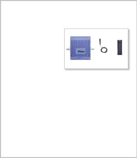
2. PACKAGE CONTENTS
2.1 801101/804002
Bi-directional Amplier
2.2 12V DC Power Supply
(Cig. Lighter Included)
2.3 Stealth Antenna
(Coax Included)
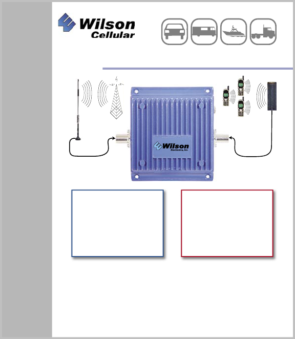
3. HOW THE 801101/804002 FUNCTIONS
The signal is received by the outside antenna from the cell site. It is then AMPLIFIED
and transmitted to your AMPS/iDEN phone through the inside antenna. When the
phone transmits, the signal is received by the inside antenna. It is then AMPLIFIED
and transmitted to the cell site through the outside antenna (not included).
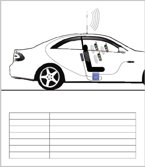
4. AMPLIFIER SYSTEM INSTALLATION (See Illustration on pg. 4)
4.1 Mounting the Amplier
4.1.1 Mount the AMPLIFIER under the dash or vehicle seat.
NOTE: The amplier should be mounted to the selected location using
mounting screws. (Mounting screws not included.)
NOTE: Mount the AMPLIFIER away from direct sunlight, excessive heat
and/or moisture. The amplifier needs proper ventilation.
DO NOT place the amplifier in an air-tight enclosure.
4.2 Installing the
Wilson Cellular
Inside Antenna (Included)
4.1.1 Connect the Inside Antenna to the side labeled “INSIDE ANTENNA”
on the AMPLIFIER.

2
3
4.2.2 The inside antenna should be mounted about 1-2 feet from where the phone
is used. The best place to mount the inside antenna is shoulder height on the
side of the drivers seat. Do not mount on a surface within 4 inches of metal.
(Metal found in the seat should not effect the antenna)
NOTE: Do not mount on a windshield.
NOTE: If the vehicle has a sunroof, place the outside antenna away from the
sunroof so that the inside antenna is shielded.
WARNING: The inside antenna used with this amplier must be
mounted with a separation distance of at least 8 inches (20cm) from all
persons and must not be co-located or operating in conjunction with any
other antenna or amplier.
4.3 Installing the
Wilson Cellular
Outside Antenna (Sold Separately)
4.3.1 Select an outside mounting location. For best performance try to keep
the antenna centered on the car’s/truck’s roof.
4.3.2 The outside antenna should be located in an area with at least a 12”
radius clear of obstructions, and other radiating elements.
NOTE: When using a magnet mount, NMO or trucker antenna, keep the
separation distance between the inside and outside antennas at least
4ft. When using a glass mount antenna, keep the separation distance
between the inside and outside antennas at least 5ft.
WARNING: The outside antenna must be mounted with a separation dis-
tance of at least 15.5 inches from any of the vehicle occupants or nearby
persons and must not be co-located or operating in conjunction with
any other antenna or amplifier. Use of a cellular amplifier with antenna
gains higher than 5.12dBi is in violation of FCC regulations for which the
offender is fully liable. All Wilson Mobile Antennas are 5.12dBi or less.
4.3.3 Connect the Outside Antenna to the AMPLIFIER side labeled
“OUTSIDE ANTENNA”.
4.4 Connect the 12V Power Supply
4.4.1 Connect the large end of the 12V Power Supply into your cigarette lighter
and the other end into the input on your amplier labeled “DC 12V IN”.
NOTE: If the power light does not turn on, press the on/off switch (white button)
on the power supply.
4
5
5. AMPLIFIER SPECIFICATIONS FOR AMPS MODEL
Part #: 801101
Frequency 824-849MHz Uplink 869-894MHz Downlink
Gain (up/down) (37dB/37dB)
Flatness (up/down) (+/- 3dB / +/-4dB)
Max RF (up/down) (+35dBm/+15dBm)
Noise Figure (down) (4.5dB)
Isolation Uplink/Downlink More than 90dB
Power Consumption 12V, 1.5A
Amplier
4
5
MOBILE
AMPLIFIER LAYOUT
AMPLIFIER SPECIFICATIONS FOR iDEN MODEL
Part #: 804002
Frequency 806-821MHz Uplink 851-866MHz Downlink
Gain (up/down) (37dB/37dB)
Flatness (up/down) (+/- 3dB/+/-3dB)
Max RF (up/down) (+35dBm/+15dBm)
Noise Figure (down) (4.5dB)
Isolation Uplink/Downlink More than 90dB
Power Consumption 12V, 1.5A
AMPS/iDEN AMPLIFIER PHYSICAL
SPECIFICATIONS
Connectors FME-Male 50 Ohms
Dimensions 5.5x4.3x1.4 (inch) or
14.0x10.8x3.5 (cm)
Weight 1.32 Pounds or 600G

6
7
6. FEATURES
Wireless Operation - No Physical Connection to Cellphone
The 801101/804002 Amplier greatly improves signal strength inside a vehicle
without a physical connection to your phone. It also allows multiple phones to be
used simultaneously.
Advanced Electronics Receive & Transmit Better Than Your Cellphone
The Wilson Cellular Amplier has a better receiver than what’s in your cellphone.
Its advanced electronics are very sensitive and able to receive small signals that
would go undetected by most cellphones. It also has a better transmitter with double
the power of your cellphone. This allows your voice to be heard by distant cell sites,
increasing coverage up to 50 miles or more.
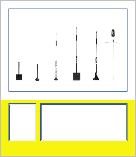
7. OPTIONAL ACCESSORIES/ANTENNA OPTIONS
7.1 Outside Antenna Options
See page 8
7.2 N-Female To FME-Female Adapter - Adapts 9913 Coax to t the
801101/804002 Bi-directional Amplier
8. TECH SUPPORT
If you need further assistance with your installation:
1) Call us Toll-Free at 866-294-1660
2) E-mail tech support at tech@wilsonelectronics.com
3) Go to www.wilsonelectronics.com
Our Hours of Operation are: 8:00 AM – 4:30 PM (Mountain Time)
9. NOTES & WARNINGS
NOTE: When using a magnet mount, NMO or trucker antenna, keep the separation
distance between the inside and outside antennas at least 4ft. When using
a glass mount antenna, keep the separation distance between the inside and
outside antennas at least 5ft.

6
7
WARNING: Verify that both the outside antenna and then inside antenna are connected
before powering up the amplier.
WARNING: The outside antenna must be mounted with a separation distance of at least 15.5
inches from any of the vehicle occupants or nearby persons and must not be
co-located or operating in conjunction with any other antenna or amplifier. Use
of a cellular amplifier with antenna gains higher than 5.12dBi is in violation
of FCC regulations for which the offender is fully liable. All Wilson Mobile
Antennas are 5.12dBi or less.
WARNING: The inside antenna used with this amplier must be mounted with a separation
distance of at least 8 inches (20cm) from all persons and must not be co-
located or operating in conjunction with any other antenna or amplier.
The information provided by Wilson Electronics, Inc. is believed to be complete and accurate.
However, no responsibility is assumed by Wilson Electronics, Inc. for any business or per-
sonal losses arising from its use, or for any infringements of patents or other rights of third
parties that may result from its use.
Copyright © 2004 Wilson Electronics, Inc.
Operation is subject to the following two conditions: (1) This device may not cause interference,
and (2) this device must accept any interference, including interference that may cause undesired
operation of this device.
Leaving the amplifier on in an unused vehicle for days may drain your battery. This can be
avoided by plugging into an ignition switched outlet or by using the small white switch located
on the power supply.
The Manufacturer’s rated output power of this equipment is for single carrier operation. For
situations when multiple carrier signals are present, the rating would have to be reduced by 3.5
dB, especially where the output signal is re-radiated and can cause interference to adjacent band
users. This power reduction is to be by means of input power or gain reduction and not by an
attenuator at the output of the device.
1. In order to prevent input levels in excess of this maximum input level from distorting or otherwise
overdriving this amplifier. For uplink, the maximum RF output is 31 dBm. For downlink, the maxi-
mum RF output is 15 dBm. When the RF ouput is higher than the maximum level due to the input,
a switch circuit of this amplifier will be active, and it will drop the RF output by as much as -50 dB.
2. The voltage and current into the final amplification stage are:
TX: 5VDC 300mA-1.5A
RX: 3.6VDC 50mA
8
For more options visit www.wilsonelectronics.com
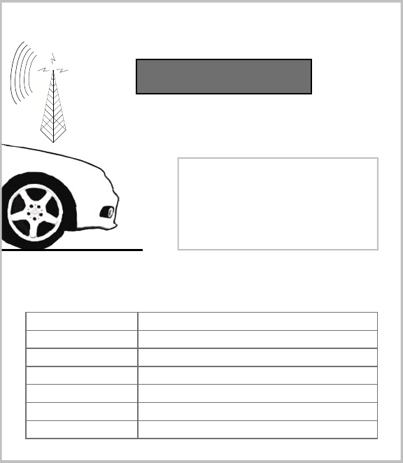
15 DAY
MONEY BACK
GUARANTEE
All Wilson products
have a 15 day
money back
guarantee with
Proof of Purchase
1 YEAR WARRANTY
The Wilson amplifier is warranted for one year against defects in workmanship
and/or materials and will be repaired or replaced, at the discretion of the manufac-
turer, to the original purchaser with dated proof of purchase or sales receipt.
If you have questions about your amplifier please call technical support
call 1-866-294-1660 or E-mail tech@wilsonelectronics.com
Most warranty cases can be handled by taking the amplifier and the re-
ceipt to the store where it was purchased. If inconvenient, the amplifier and a
copy of the receipt, may be sent to the factory, at purchasers expense, where
it may be repaired or replaced and returned shipping paid. Warranty does not
cover damages caused by abuse, misuse, and negligence.
OUTSIDE ANTENNA
OPTIONS