Wingsafe Technology WBU-900A 900MHz Long Range Reader User Manual Users manual
Wingsafe Technology Inc. 900MHz Long Range Reader Users manual
Users manual
User Manual
Of
WBU-900A

User Manual
1
Content
1Introduction .................................................................................................................................2
1.1Functions ........................................................................................................................................2
1.1.1WorkingMode.........................................................................................................................2
1.1.2Parameters ..............................................................................................................................2
1.2SystemDescription .........................................................................................................................3
1.2.1Components ............................................................................................................................3
1.2.2Host .........................................................................................................................................3
1.2.3Interface ..................................................................................................................................4
1.2.4LEDIndicator ...........................................................................................................................4
1.2.5Buzzer......................................................................................................................................4
1.2.6Label ........................................................................................................................................ 4
1.3CautionsbeforeUsing ....................................................................................................................5
2ReaderInstallation........................................................................................................................5
2.1InstallationOverview......................................................................................................................5
2.2InstallationSummary .....................................................................................................................6
Appendix1Howtochecktheperformancesimply? .........................................................................6

User Manual
2
This device complies with part 15 of the FCC Rules. Operation is subject to the following
two conditions: (1) This device may not cause harmful interference, and (2) this device must
accept any interference received, including interference that may cause undesired operation.
Changes or modifications not expressly approved by the party responsible for compliance
could void the user's authority to operate the equipment.
FCC Radiation Exposure Statement:
This equipment complies with FCC radiation exposure limits set forth for an uncontrolled
environment .This equipment should be installed and operated with minimum distance 20cm
between the radiator& your body.
This transmitter must not be co-located or operating in conjunction with any other antenna or
transmitter.
1 Introduction
1.1 Functions
1.1.1 Working Mode
The device has two working mode. one is Interval Scan Mode ,In this mode ,if reader Power
on ,it will scan the tag intermittently;The other mode is Trigger Mode, in this mode, only if the
voltage of the Trigger Pin is logic 0,the reader begins to scan the tag automatically.
When reader enters into the scanning status, it will capture the programmed identification
information of the tags which within the L5121’s read range automatically, and transmits the data
to a local host computer or process through the specified communication interface (RS232 or
RS485).
The default working mode of the reader is Interval Scan Mode if need preconfigured to
Trigger Mode or other communication interface, please consult with the Hawkvor before
purchasing.
1.1.2 Parameters
The parameters of the reader as Table 1.1.2-1
User Manual
3
Table 1.1.2-1
1.2 System Description
1.2.1 Components
The package of the reader contents the components list in the Table 1.2.1-1.
Table1.2.1-1
No Component Specification Quantity Remark
1 Host 370* 360 * 96 mm 1 PC With Fixed Holder
2 Power Adapter 12V/4A 1 PC
3 Power Code 1.8 m in length 1 PC
4 RS232 Cable 1 PC
5 Test Tag 86 * 54 * 1.0 mm 1 PC Optional
6 Definition of Connection Pins 1 PC
7 Packing List 1 PC
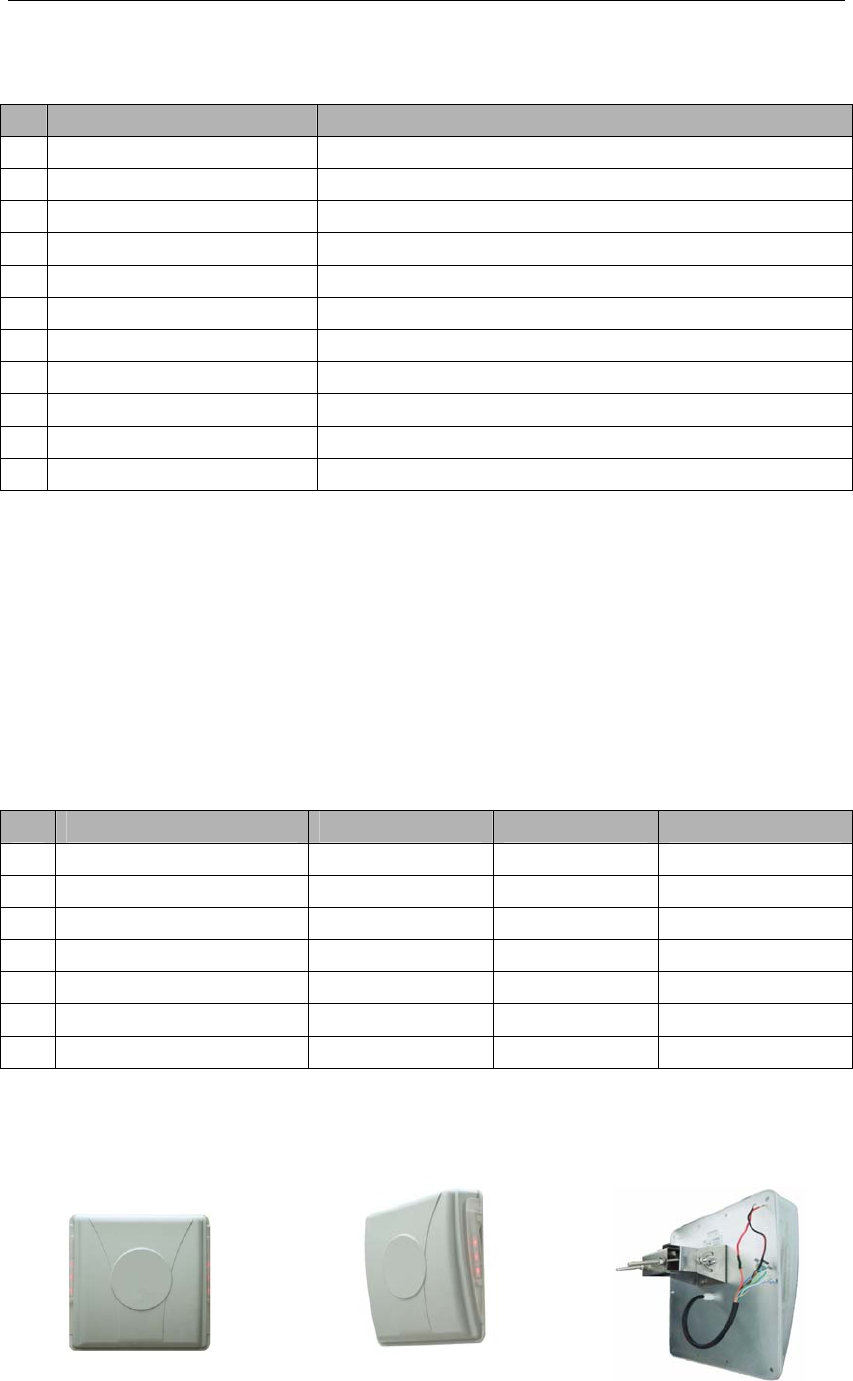
1.2.2 Host
Over view Side view Back view
No Parameter Value
1 Operating Frequency 902~928 MHz FHSS
2 Transmitter Power 0 to 20dBm (programmed by software)
3 Supply Voltage 10~25 VDC +5%/-1%, Ripple: maximum 50 mV
4 Communication Rates 9600 bps
5 Power Consumption maximum 10 W
6 Interfaces Optional RS232,RS485
7 Overall Size 370* 360 * 96 mm
8 Package Size 430 * 420 * 190 mm
9 Net Weight: 3.0 KGS
10 Operating Temperature -20°C to +70°C
11 Storage Temperature -40°C to +85°C

User Manual
4
1.2.3 Interface
.Hawkvor Reader L5121 can be able to provide 5 group interface, for details please refer to
Table 1.2.3-1
Table 1.2.3-1 Definition of the Interface
No Interface Type Definition Color Remark
+12 V Red Two-core
1 Power GND Black Two-core
232(RX) Grey 2-Pin
232(TX) Blue 3-Pin
2 RS232
GND Yellow
485+ White
485- Light Green
3 RS485
GND Yellow
Reserved for RS485
W0D0 Purple
W0D1 Green
4 Wiegand
GND Yellow
Reserved
Trigger Orange
5 Trigger GND Yellow
Reserved for Trigger
Mode
1.2.4 LED Indicator
There are two rows LED indicators on the Hawkvor Reader Model L5121, when Red LED
lighting means the reader is power on, while Blue LED lighting means t the reader captures the
data of the tag,
1.2.5 Buzzer
When the reader captures the data of the tag, the buzzer will beep.
1.2.6 Label
No Label Type Definition Position
1 SN Label The serial number of the host Bakc Board
2 Interface Label The specified communication interface of the host Back Board
3 Capital Letter Label A or B or C or D or E Back Board
Remark:

User Manual
5
1. The SN label is the identification of each reader, don’t tear off during using.
2. Please check the interface configuration with the Interface Label, if not correct, please contact with
Hawkvor.
3. Don’t install two hosts with the same Capital Letter Label within 20 meters scope.
1.3 Cautions before Using
1. Please use the 12V 4A DC Power Adapter which enclosed the package for connecting the
host with the power.
2. 12V 4A DC Power Adapter which enclosed the package is not waterproof, you need to be
covered when used.
3. The power code which connected Power Adapter and the 220V AC Power needs to be
connected the ground wire to prevent lightning strikes.
4. Please make well the insulation protection between different wires to prevent the short
circuit damage.
5. Please read this instruction manual carefully before installation.
2 Reader Installation
2.1 Installation Overview
The Reader has been designed with easy installation in mind. The Figure 2.1-1 provides you
with any details that you will need to know.
Figure 2.1-1 Installation
2.2 M

User Manual
6
2.2 Installation Summary
There are two ways for installing the reader by install position. One installs on the side of the
lane which we called Side Installation, while the other installs on the overhead of the lane which
we called Overhead Installation. For details please refer to the Table 2.2-1
Table 2.2-1
Install Way Advantage Disadvantage
Side Installation 1. Easy to install with the pole
2. Easy for maintenance
1.The read range is subject to the install height & the
angle of the reader
2. The tag should installed to the side near the reader
Overhead Installation 1. The reader range is larger & wider
2. The tag position is more flexible
1. It’s not easy for maintenance due to the install
height of the reader.
2. The extension power wire & communication wire
requires longer & thicker
When the site meets following conditions, we suggest choosing the Overhead Installation way, otherwise
choosing the Side Installation way:
1. There are many types of car, especially with both large vehicle and small car;
2. The position of the tag is different from different type of vehicles;
3. The drive position is available for both left and right side
Appendix 1 How to check the performance simply?
Purpose: When a malfunction occurs during the using, the follow steps will help you to check the
performance of the reader simply.
1. Test Sites: Open area without any barrier or block.
2. Reader Install Height: Over 2 Meter and power the reader with Power Adapter & Power Code
enclosed the package.
3. Test Tag: use the tag MICE5510 enclosed the package