Winmate WMOAP8251AG Winmate Outdoor AP User Manual Revised
Winmate Inc. Winmate Outdoor AP Revised
Winmate >
Contents
- 1. User Manual
- 2. User Manual Revised
User Manual Revised
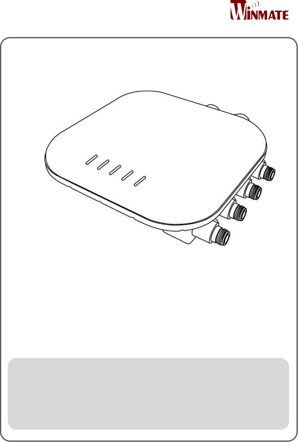
Outdoor Enterprise Access Point
WM-OAP8251AG
User Manual
Version 1.0
Document Part Number: 91711110100E

Outdoor Enterprise Access Point WM-OAP8251AG
ii
Preface
Copyright Notice
No part of this document may be reproduced, copied, translated, or transmitted in any
form or by any means, electronic or mechanical, for any purpose, without the prior written
permission of the original manufacturer.
Trademark Acknowledgement
Brand and product names are trademarks or registered trademarks of their respective
owners.
Disclaimer
We reserve the right to make changes, without notice, to any product, including circuits
and/or software described or contained in this manual in order to improve design and/or
performance. We assume no responsibility or liability for the use of the described
product(s) conveys no license or title under any patent, copyright, or masks work rights to
these products, and make no representations or warranties that these products are free
from patent, copyright, or mask work right infringement, unless otherwise specified.
Applications that are described in this manual are for illustration purposes only. We make
no representation or guarantee that such application will be suitable for the specified use
without further testing or modification.
Warranty
Our warranty guarantees that each of its products will be free from material and
workmanship defects for a period of one year from the invoice date. If the customer
discovers a defect, we will, at his/her option, repair or replace the defective product at no
charge to the customer, provide it is returned during the warranty period of one year, with
transportation charges prepaid. The returned product must be properly packaged in its
original packaging to obtain warranty service. If the serial number and the product
shipping data differ by over 30 days, the in-warranty service will be made according to the
shipping date. In the serial numbers the third and fourth two digits give the year of
manufacture, and the fifth digit means the month (e. g., with A for October, B for
November and C for December).
For example, the serial number 1W15Axxxxxxxx means October of year 2015.

Outdoor Enterprise Access Point WM-OAP8251AG
iii
Customer Service
We provide a service guide for any problem by the following steps: First, visit the website
of our distributor to find the update information about the product. Second, contact with
your distributor, sales representative, or our customer service center for technical support
if you need additional assistance.
You may need the following information ready before you call:
Product serial number
Software (OS, version, application software, etc.)
Detailed description of the problem
The exact wording of error messages
In addition, free technical support is available from our engineers every business day. We
are always ready to give advice on application requirements or specific information on the
installation and operation of any of our products.
Outdoor Enterprise Access Point WM-OAP8251AG
iv
Advisory Conventions
Four types of advisories are used throughout the user manual to provide helpful information or
to alert you to the potential for hardware damage or personal injury. These are Notes, Important,
Cautions, and Warnings. The following is an example of each type of advisory.
NOTE:
A note is used to emphasize helpful information
IMPORTANT:
An important note indicates information that is important for you to know.
CAUTION/ ATTENTION
A Caution alert indicates potential damage to hardware and explains how to avoid
the potential problem.
Une alerte d’attention indique un dommage possible à l’équipement et explique
comment éviter le problème potentiel.
WARNING!/ AVERTISSEMENT!
An Electrical Shock Warning indicates the potential harm from electrical hazards
and how to avoid the potential problem.
Un Avertissement de Choc Électrique indique le potentiel de chocs sur des
emplacements électriques et comment éviter ces problèmes.
ALTERNATING CURRENT / MISE À LE TERRE!
The Protective Conductor Terminal (Earth Ground) symbol indicates the potential
risk of serious electrical shock due to improper grounding.
Le symbole de Mise à Terre indique le risqué potential de choc électrique grave à
la terre incorrecte.

Outdoor Enterprise Access Point WM-OAP8251AG
v
Federal Communications Commission Radio Frequency Interface Statement
This equipment has been tested and found to comply with the limits for a Class B
digital device, pursuant to Part 15 of the FCC Rules. These limits are designed to provide
reasonable protection against harmful interference in a residential installation. This equipment
generates uses and can radiate radio frequency energy and, if not installed and used in
accordance with the instructions, may cause harmful interference to radio communications.
However, there is no guarantee that interference will not occur in a particular installation. If this
equipment does cause harmful interference to radio or television reception, which can be
determined by turning the equipment off and on, the user is encouraged to try to correct the
interference by one of the following measures:
Reorient or relocate the receiving antenna.
Increase the separation between the equipment and receiver.
Connect the equipment into an outlet on a circuit different from that to which the
receiver is connected.
Consult the dealer or an experienced radio/TV technician for help.
FCC CAUTION/ FCC ATTENTION
Any changes or modifications not expressly approved by the party responsible for
compliance could void the user’s authority to operate this equipment.
Tout changement ou modification non expressément approuvé par la partie
responsable de la conformité peut annuler l'autorisation de l'utilisateur d'utiliser
cet équipement.
This device complies with Part 15 of the FCC Rules. Operation is subject to the following two
conditions: (1) This device may not cause harmful interference, and (2) this device must accept
any interference received, including interference that may cause undesired operation.
IMPORTANT NOTE:
Radiation Exposure Statement
This equipment complies with FCC radiation exposure limits set forth for an uncontrolled
environment. This equipment should be installed and operated with minimum distance 41 cm
between the radiator & your body.

Outdoor Enterprise Access Point WM-OAP8251AG
vi
CE Interference Statement
Europe – EU Declaration of Conformity
This device complies with the essential requirements of the R&TTE Directive 1999/5/EC. The
following test methods have been applied in order to prove presumption of conformity with the
essential requirements of the R&TTE Directive 1999/5/EC:
• EN60950-1
Safety of Information Technology Equipment
• EN50385
Generic standard to demonstrate the compliance of electronic and electrical apparatus
with the basic restrictions related to human exposure to electromagnetic fields (0 Hz -
300 GHz)
• EN 300 328
Electromagnetic compatibility and Radio spectrum Matters (ERM); Wideband
Transmission systems; Data transmission equipment operating in the 2,4 GHz ISM band
and using spread spectrum modulation techniques; Harmonized EN covering essential
requirements under article 3.2 of the R&TTE Directive
• EN 301 893
Broadband Radio Access Networks (BRAN); 5 GHz high performance RLAN; Harmonized
EN covering essential requirements of article 3.2 of the R&TTE Directive
• EN 301 489-1
Electromagnetic compatibility and Radio Spectrum Matters (ERM); ElectroMagnetic
Compatibility (EMC) standard for radio equipment and services; Part 1: Common
technical requirements
• EN 301 489-17
Electromagnetic compatibility and Radio spectrum Matters (ERM); ElectroMagnetic
Compatibility (EMC) standard for radio equipment and services; Part 17: Specific
conditions for 2,4 GHz wideband transmission systems and 5 GHz high performance
RLAN equipment
This device is a 5GHz wideband transmission system (transceiver), intended for use in all EU
member states and EFTA countries, except in France and Italy where restrictive use applies.
In Italy the end-user should apply for a license at the national spectrum authorities in order to
obtain authorization to use the device for setting up outdoor radio links and/or for supplying
public access to telecommunications and/or network services.
This device may not be used for setting up outdoor radio links in France and in some areas the
RF output power may be limited to 10 mW EIRP in the frequency range of 2454 – 2483.5 MHz.
For detailed information the end-user should contact the national spectrum authority in France.
Outdoor Enterprise Access Point WM-OAP8251AG
vii
Safety Information
For your safety carefully read all the safety instructions before using the device. All
cautions and warnings on the equipment should be noted. Keep this user manual for
future reference.
CAUTION/ATTENTION
Do not cover the openings!
Ne pas couvrir les ouvertures!
*Let service personnel to check the equipment in case any of the following
problems appear:
o The power cord or plug is damaged.
o Liquid has penetrated into the equipment.
o The equipment has been exposed to moisture.
o The equipment does not work well or you cannot get it to work
according to the user manual.
o The equipment has been dropped and damaged.
o The equipment has obvious signs of breakage.
Do not leave this equipment in an uncontrolled environment where the storage
temperature is below -20°C (-4°F) or above 60°C (140°F). It may damage the
equipment.
CAUTION/ATTENTION
Use the recommended mounting apparatus to avoid risk of injury.
Utiliser l’appareil de fixation recommandé pour éliminer le risque de
blessure.
WARNING! / AVERTISSEMENT!
Only use the connection cords that come with the product. When in doubt,
please contact the manufacturer.
Utiliser seulement les cordons d’alimentation fournis avec le produit. Si
vous doutez de leur provenance, contactez le manufacturier.
WARNING!/ AVERTISSEMENT!
Always ground yourself against electrostatic damage to the device.
Toujours vérifier votre mise à la terre afin que l’équipement ne se
décharge pas sur vous.
Outdoor Enterprise Access Point WM-OAP8251AG
viii
Professional Installation Instruction
Installation Personal
This product is designed for specific application and needs to be installed by a qualified personal
who has RF and related rule knowledge. The general user shall not attempt to install or change
these settings.
Installation Location
The product shall be installed at a location where the radiating antenna can be kept 41cm from
nearby person in normal operation condition to meet regulatory RF exposure requirement.
External Antenna
Use only the antennas which have been approved by the applicant. Any non-approved antenna(s)
may produce unwanted spurious or excessive RF transmitting power which may lead to the
violation of FCC/IC limit and is prohibited.
Installation Procedure
Please refer to user’s manual for details on proper installation methods.
WARNING! / AVERTISSEMENT!
Please carefully select the installation position and make sure that the final
output power does not exceed the limit set force in the relevant rules. A
violation of these rules could lead to serious federal penalties.
Veuillez sélectionner soigneusement la position d'installation et veiller à ce
que la puissance de sortie finale ne dépasse pas la force de consigne fixée
dans les règles correspondantes. Une violation de ces règles pourrait
entraîner de graves sanctions fédérales.

Outdoor Enterprise Access Point WM-OAP8251AG
ix
About This User Manual
This User Manual provides information about using the Winmate® Outdoor Enterprise Access
Point WM-OAP8251AG.
The documentation set for the WM-OAP8251AG provides information for specific user needs,
and includes:
The WM-OAP8251AG User Manual – contains detailed description how to use the
display, its components and features.
The WM-OAP8251AG Quick Start Guide – describes how to get your WM-OAP8251AG
up and running.
NOTE:
Some pictures in this guide are samples and can differ from actual product.
Revision History
Version
Date
Note
1.0
15-Nov-2016
Preliminary release

Outdoor Enterprise Access Point WM-OAP8251AG
x
Contents
Preface ............................................................................................................................... ii
About This User Manual ..................................................................................................... ix
Chapter 1: Introduction ..................................................................................................... 14
1.1 Overview .................................................................................................................. 14
1.2 Product Features ...................................................................................................... 14
1.3 Hardware Specifications .......................................................................................... 15
1.4 Function Block Diagram ........................................................................................... 16
1.5 Package Contents ..................................................................................................... 17
1.6 Minimum Requirements .......................................................................................... 17
1.7 Appearance and Dimensions ................................................................................... 18
Chapter 2: Hardware Installation ....................................................................................... 21
2.1 Connecting the Access Point .................................................................................... 21
2.1.1 Managed Access Point with Wireless Management Switch ......................... 21
2.1.2 Stand-alone Access point Installation ........................................................... 22
Chapter 3: Mounting ......................................................................................................... 24
3.1 Wall Mounting the AP .............................................................................................. 24
3.2 Pole Mount the AP ................................................................................................... 26
Chapter 4: Configuring Your Access Point .......................................................................... 29
4.1 Default Settings ........................................................................................................ 29
4.2 Web Configuration ................................................................................................... 29
Chapter 5: Building a Wireless Network ............................................................................. 32
5.1 Access Point Mode ................................................................................................... 32
5.2 WDS AP Mode .......................................................................................................... 34
5.3 WDS Bridge Mode .................................................................................................... 35
5.4 WDS Station Mode ................................................................................................... 36
5.5 AP Mesh Mode ......................................................................................................... 37
5.6 Mesh Only Mode ...................................................................................................... 38
Chapter 6: Software Settings ............................................................................................. 40
6.1 Main Status .............................................................................................................. 40
6.1.1 Save Changes ................................................................................................. 40

Outdoor Enterprise Access Point WM-OAP8251AG
xi
6.1.2 Device Status ................................................................................................. 40
6.2 Connection ............................................................................................................... 42
6.2.1 Connection List 2.4 GHz/5 GHz ..................................................................... 42
6.2.2 WDS Link List2.4 GHz/5 GHz ......................................................................... 42
6.2.3 The Mesh Link List ......................................................................................... 43
6.3 Network ................................................................................................................... 43
6.3.1 Basic IP Settings ............................................................................................. 43
6.4 Wireless Settings ...................................................................................................... 45
6.4.1 Wireless Settings ........................................................................................... 45
6.4.2 Wireless Network 2.4 GHz/5 GHz .................................................................. 45
6.4.3 SSID Profiles 2.4 GHz/5 GHz .......................................................................... 47
6.4.4 Wireless Security ........................................................................................... 48
6.4.5 Wireless MAC Filtering .................................................................................. 48
6.5 Wireless Advanced ................................................................................................... 49
6.5.1 Wireless Traffic Shaping ................................................................................ 49
6.5.2 WPA-PSK (WPA Pre-Shared Key) Encryption ................................................ 49
6.5.3 WPA Mixed-Enterprise: Access Point / WDS AP Mode ................................. 50
6.5.4 Fast Roaming ................................................................................................. 50
6.5.5 WDS Link Settings .......................................................................................... 51
Chapter 7: Management ................................................................................................... 55
7.1 Management VLAN Settings .................................................................................... 55
7.2 Advanced Settings .................................................................................................... 55
7.2.1 SNMP Settings ............................................................................................... 55
7.2.2 CLI Settings .................................................................................................... 57
7.2.3 Email Alerts .................................................................................................... 57
7.3 Time Zone................................................................................................................. 58
7.3.1 Time Setting ................................................................................................... 58
7.4 Auto Reboot Settings ............................................................................................... 58
7.5 Wi-Fi Scheduler ........................................................................................................ 59
7.6 Tools ......................................................................................................................... 60
7.6.1 Ping Test Parameters ..................................................................................... 60

Outdoor Enterprise Access Point WM-OAP8251AG
xii
7.6.2 Speed Test Parameters/LED Control ............................................................. 61
7.6.3 LED Control .................................................................................................... 61
7.6.4 Device Discovery ........................................................................................... 61
7.7 Account .................................................................................................................... 62
7.7.1 Account Settings ............................................................................................ 62
7.8 Firmware .................................................................................................................. 63
7.8.1 Firmware Upgrade ......................................................................................... 63
7.9 Backup/Restore ........................................................................................................ 63
7.10 Log .......................................................................................................................... 64
7.10.1 System Log ................................................................................................... 64
7.10.2 Remote Log .................................................................................................. 64
7.10.3 Logout .......................................................................................................... 64
7.10.4 Reset ............................................................................................................ 65

Outdoor Enterprise Access Point WM-OAP8251AG
13
Introduction
This chapter provides the WM-OAP8251AG
Outdoor Enterprise Access Point product
overview, describes its features and hardware
specifications.

User Manual Chapter 1 Introduction
Outdoor Enterprise Access Point WM-OAP8251AG
14
Chapter 1: Introduction
This chapter provides the Outdoor Enterprise Access Point WM-OAP8251AG product
overview, describes its features and hardware specifications.
1.1 Overview
Thank you for choosing the Winmate® Outdoor Enterprise Access Point.
The WM-OAP8251AG is an enterprise class, outdoor dual radio 2.4G (11n) and 5G (11ac
Wave2) concurrent 4x4 MU-MIMO access point with built-in internal antenna. The
device has two Ethernet ports and one of it is a PSE port that supplies power to the
remote unit. With certified IP67 protection, Winmate® Outdoor Enterprise Access Point
is designed to deliver high reliability under harsh outdoor environment.
1.2 Product Features
Winmate® Outdoor Enterprise Access Point WM-OAP8251AG offers the following
features:
Main Chip:
o Processor: Qualcomm QCA8068B, dual core, 1.4GHz
o Radios 4x4 dual band dual concurrent
Radio 1: QCA9990B 4x4 to support 2.4GHz
Radio 2: QCA9990B 4x4 to support 5GHz
o Ethernet PHY: AR8035B*1 + AR8033B*1 (Industrial graded components)
Available interface:
o 2 x Gigabit Ethernet (RJ45)
o 1 x Console (RJ45)
o LEDs
o Gore vent for pressure equalization
o N-type connectors for external antenna model
IP67 compliance enclosure design
Ethernet surge protection support (4KV)
OAP8251AG can be powered with 802.3at+ (60W) Power Source on the 1st LAN
port (PD) and provide power to other device through the 2nd LAN port (PSE).
Max power consumption is < 55W when operating as OAP8251AG and providing
802.3af power on 2nd LAN
Pole mount and wall mount locking mechanism

User Manual Chapter 1 Introduction
Outdoor Enterprise Access Point WM-OAP8251AG
15
1.3 Hardware Specifications
Model Name
WM-OAP8251AG
Hardware
Specifications
Standard
Dual band dual radio (Concurrent)
Main Chip
MCU: Qualcomm QCA8068B
RF: Qualcomm QCA9990B*2
GE Ethernet PHY: AR8035B + AR8033B
Memory
Flash:
NAND flash 512MB (Optional)
SPI NOR flash 32MB
DDR3: 512MB*2 (Note: 1G max.)
Physical Interface
2 x RJ-45 for 10/100/1000 Gigabit Ethernet
8 N-Type connector
1 x RJ-45 console port
5 x LEDs
Surge Protection
EN 61000-4-5 (4KV surges in the ant) (optional)
EN 55024 (4KV surges line to ground)
Power Requirements
PD: IEEE 802.at+ compliance
PSE: IEEE 802.3af
Mechanical
Environment
Temperature Range
Operating -30°C~60°C
Storage -40°C to 70°C (-22°F to 158°F)
Humidity
(non-condensing)
5%~90% typical
Enclosure Design
IP67
Wind Survivability
Up to 145mph (232kph)
Dimensions
(L x W x H)
210mm x 210mm x 51mm
Weight
2.0 kg
Accessory List
PoE Adapter
EAP5006GAT
Bracket (Optional)
Wall Mount, Pole Mount
Cable (Optional)
Grounding cable (Green) AWG10 180cm
Compliance
Standard
Safety
EN60950-1, EN60950-22 (Capable but not certified)
UL/cUL 60950-1. 60950-22 (Capable but not
certified)
Radio Approvals
FCC Part 15.247, 15.407
CE EN300.328, EN301.893
Maximum
Output Power
Maximum
Output Power
2.4GHz: 27.88dBm
5GHz Band 1: 24.84dBm
5GHz Band 4: 27.36dBm
User Manual Chapter 1 Introduction
Outdoor Enterprise Access Point WM-OAP8251AG
16
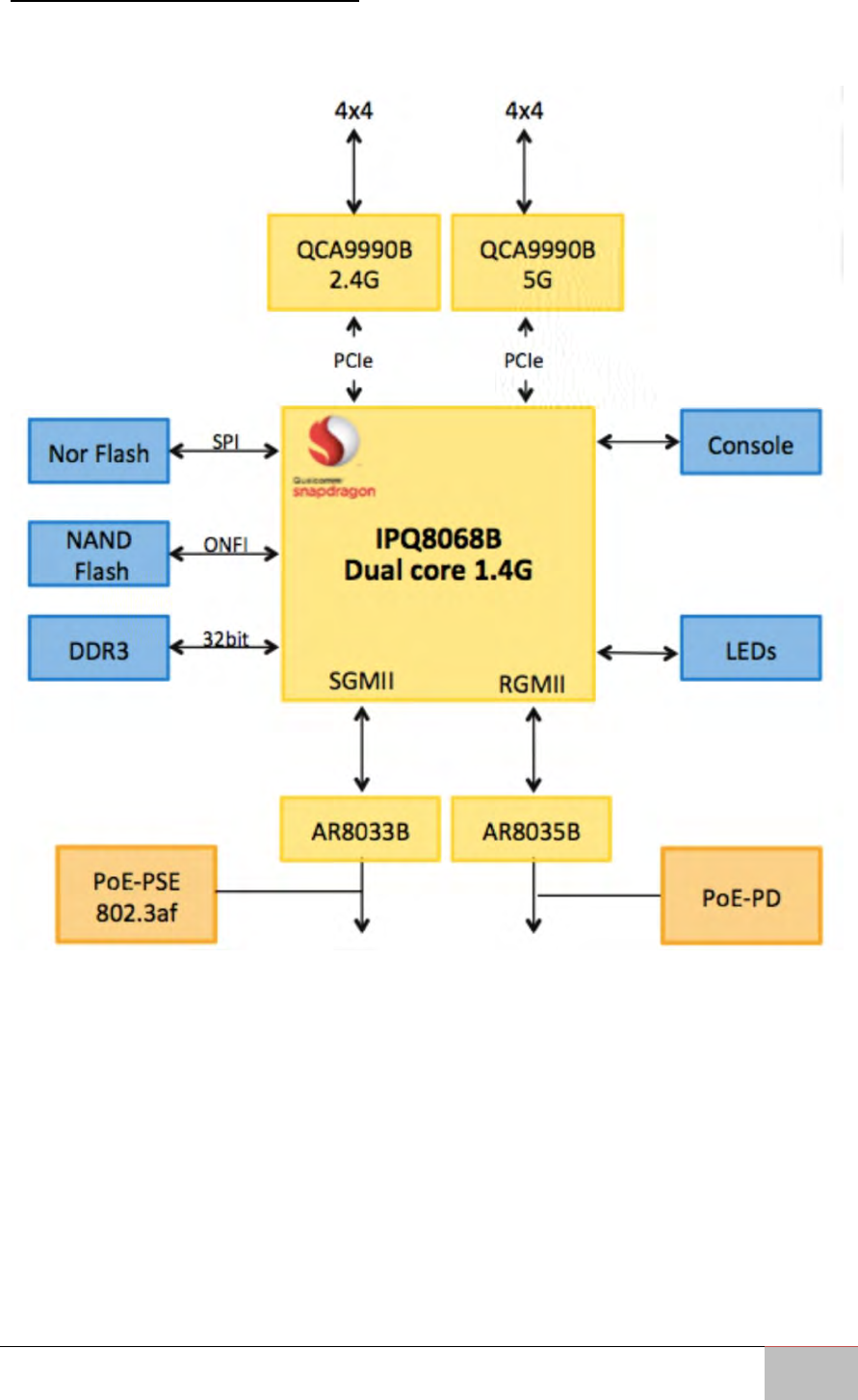
1.4 Function Block Diagram
The picture below shows the WM-OAP8251AG function block diagram:
User Manual Chapter 1 Introduction
Outdoor Enterprise Access Point WM-OAP8251AG
17
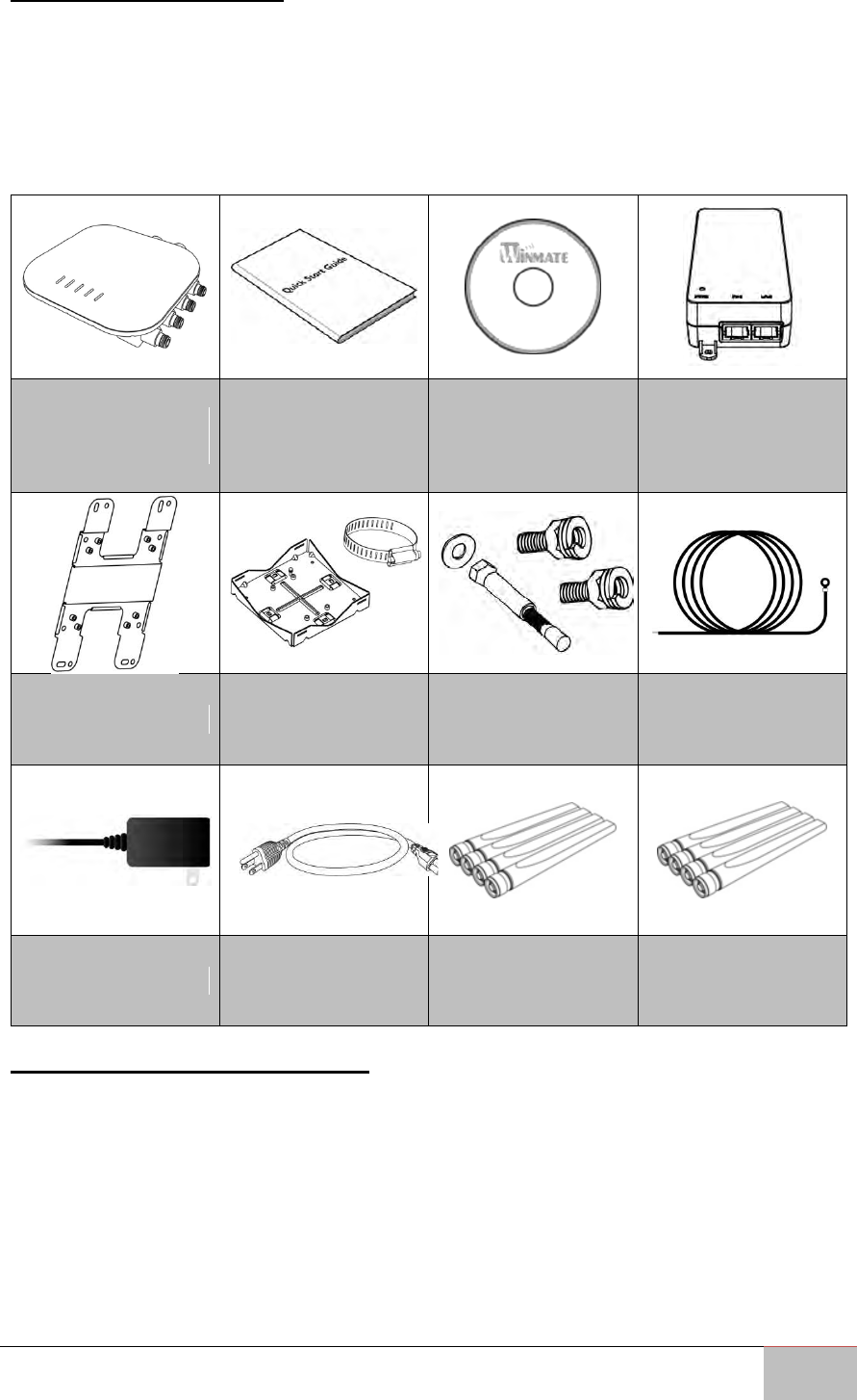
1.5 Package Contents
Carefully remove the box and unpack Outdoor Enterprise Access Point WM-OAP8251AG.
Please check if all the items listed below are inside your package. If any of these items
are missing or damaged contact us immediately.
Standard factory shipment list includes the following items:
Access Point
WM-OAP8251AG
Quick Start Guide
(Hardcopy)
User Manual
EzMaster
Software & User
Manual
PoE Injector
Wall Mounting Kit
Pole Mounting Kit
Mounting Screws
and Bolts
Ground Cable
(Green)
AWG10 180cm
Power Adapter
Power Cable
2.4GHz Detachable
Antennas x 4
5GHz Detachable
Antennas x 4
1.6 Minimum Requirements
Broadband Internet Service
(Cable or DSL Modem)
Internet Browser
(Internet Explorer, Safari, Firefox, Chrome, Edge)
User Manual Chapter 1 Introduction
Outdoor Enterprise Access Point WM-OAP8251AG
18
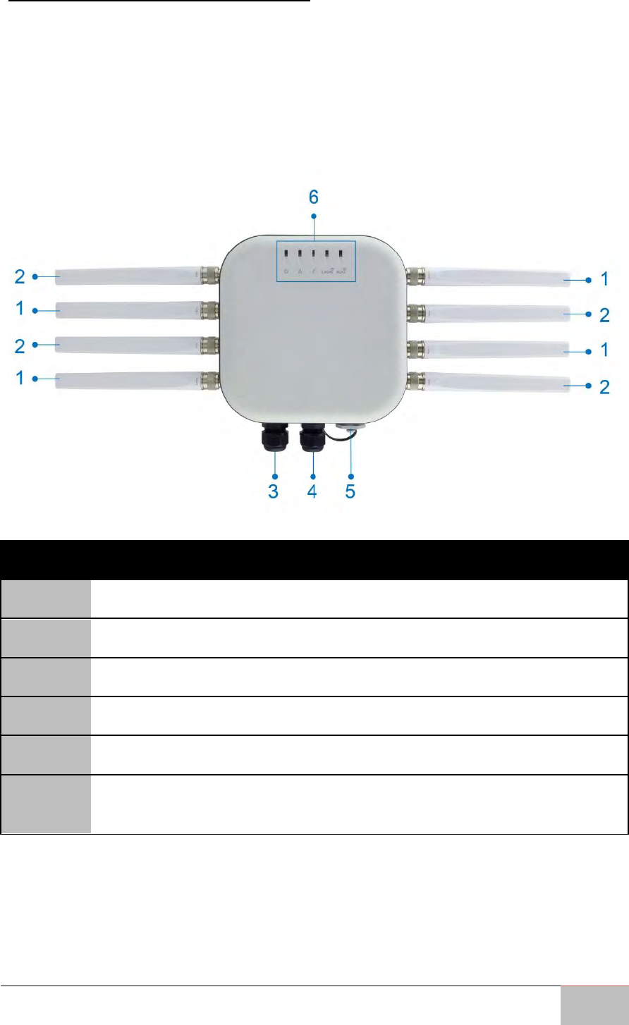
1.7 Appearance and Dimensions
This section includes mechanical drawing and dimensions of the WM-OAP8251AG.
Unit dimensions (L x W x H): 210mm x 210mm x 51mm
Weight: 1.5 kg
Front View
No.
Description
1
2.4 GHz Antennas: Detachable 5 dBi 2.4 GHz omni-directional
2
5 GHz Antennas : Detachable 7 dBi 5 GHz omni-directional
3
LAN Port 1 (802.3at PoE Input): Ethernet port for RJ-45 cable.
4
LAN Port 2 (802.3af PSE Output): Ethernet port for RJ-45 cable.
5
Console/ Reset: Console panel/ reset button.
6
LED Indicators: LED lights for Power, LAN Port 1, LAN Port 2, 2.4 GHz
Connection and 5 GHz Connection.
User Manual Chapter 1 Introduction
Outdoor Enterprise Access Point WM-OAP8251AG
19
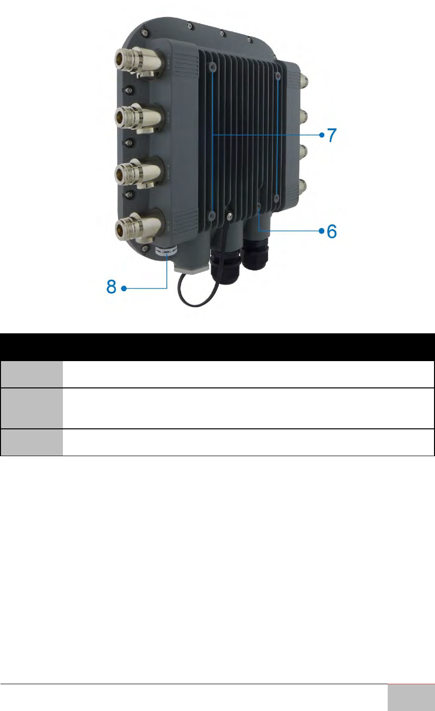
Rear View
No.
Description
6
Ground
7
Mounting Holes: Using the provided hardware, the WM-OAP8251AG can
be attached to a wall or pole.
8
Optional M12 Connector

Outdoor Enterprise Access Point WM-OAP8251AG
20
Hardware Installation
This chapter provides information on how to
use external I/O and the installation of the
WM-OAP8251AG hardware.
User Manual Chapter 2 Hardware Installation
Outdoor Enterprise Access Point WM-OAP8251AG
21
Chapter 2: Hardware Installation
This chapter provides information on how to install the WM-OAP8251AG Outdoor
Access Point hardware.
2.1 Connecting the Access Point
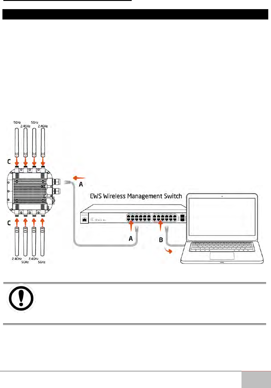
2.1.1 Managed Access Point with Wireless Management Switch
This diagram depicts the hardware configuration.
Follow the instructions below to establish the connection to the Access Point.
1. Connect one end of the Ethernet Cable into the main LAN Port (PoE) of Managed
Access Point and the other end to the Ethernet Port on the Wireless
Management Switch.
2. Connect another Ethernet Cable into an Ethernet Port on the front panel of the
WM-OAP8251AG and the other end to the Ethernet Port on the computer.
3. Screw the provided antennas to the device as shown on the illustration below.
IMPORTANT:
The Access Point supports both IEEE 802.3at PoE (Power over Ethernet)
and the included power injector. You may use either one as the power
source. Do NOT use both at the same time.
User Manual Chapter 2 Hardware Installation
Outdoor Enterprise Access Point WM-OAP8251AG
22
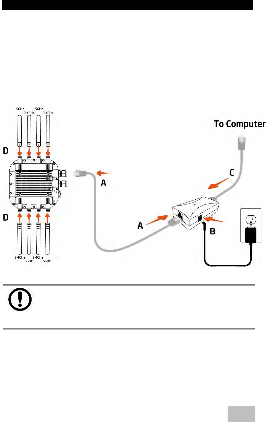
2.1.2 Stand-alone Access point Installation
Follow the instructions below to establish the connection to the Access Point.
A. Connect one end of the Ethernet Cable into the main LAN Port (PoE) of the
Access Point and the other end to the AP Ethernet Port.
B. Connect the Power Adapter to the DC-IN port of the PoE injector and plug the
other end into an electric outlet.
C. Connect the second Ethernet cable into the LAN port of the PoE injector and the
other end to the Ethernet port on the computer.
D. Screw on the provided antennas to the device as shown on the illustration below.
IMPORTANT:
The Access Point supports both IEEE 802.3at PoE (Power over Ethernet)
and the included power injector. You may use either one as the power
source.
Do NOT use both at the same time.

Outdoor Enterprise Access Point WM-OAP8251AG
23
Mounting
This chapter describes how to mount EAC-PRO
Embedded Computer.
User Manual Chapter 3 Mounting
Outdoor Enterprise Access Point WM-OAP8251AG
24
Chapter 3: Mounting
This chapter describes how to mount the Outdoor Enterprise Access Point WM-
OAP8251AG.
Outdoor Enterprise Access Point WM-OAP8251AG supports two types of mounting:
Wall Mount
Pole Mount
NOTE:
Wall and pole mounting kits are included in the package of Outdoor
Enterprise Access Point WM-OAP8251AG.
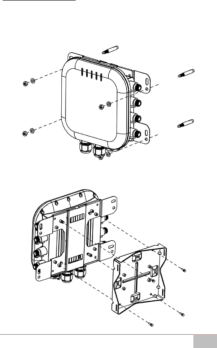
3.1 Wall Mounting the AP
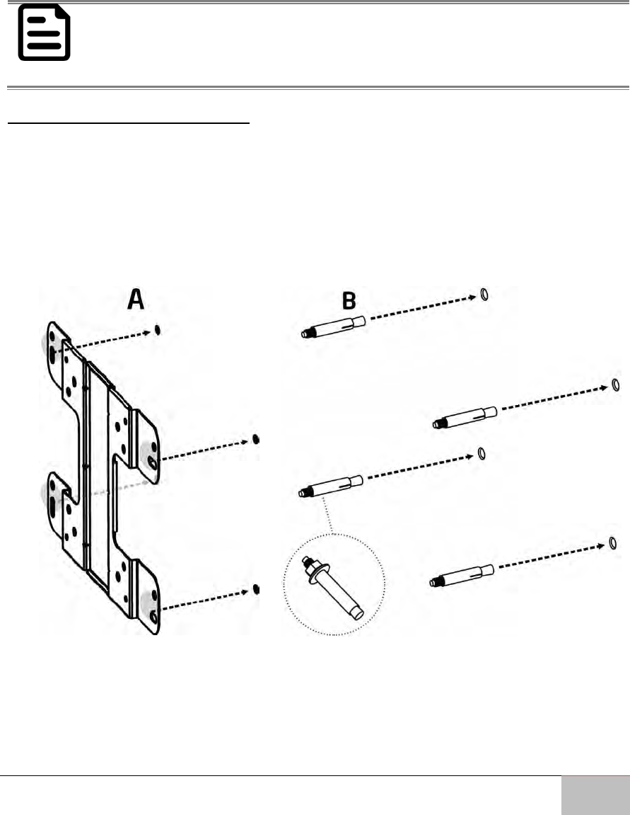
To attach the WM-OAP8251AG to a wall using wall mounting kit:
A. Mark the four locations of the mounting holes on the flat mounting surface.
B. Drill a 37mm deep 8mm hole in the markings and hammer the bolts into the
openings.
User Manual Chapter 3 Mounting
Outdoor Enterprise Access Point WM-OAP8251AG
25
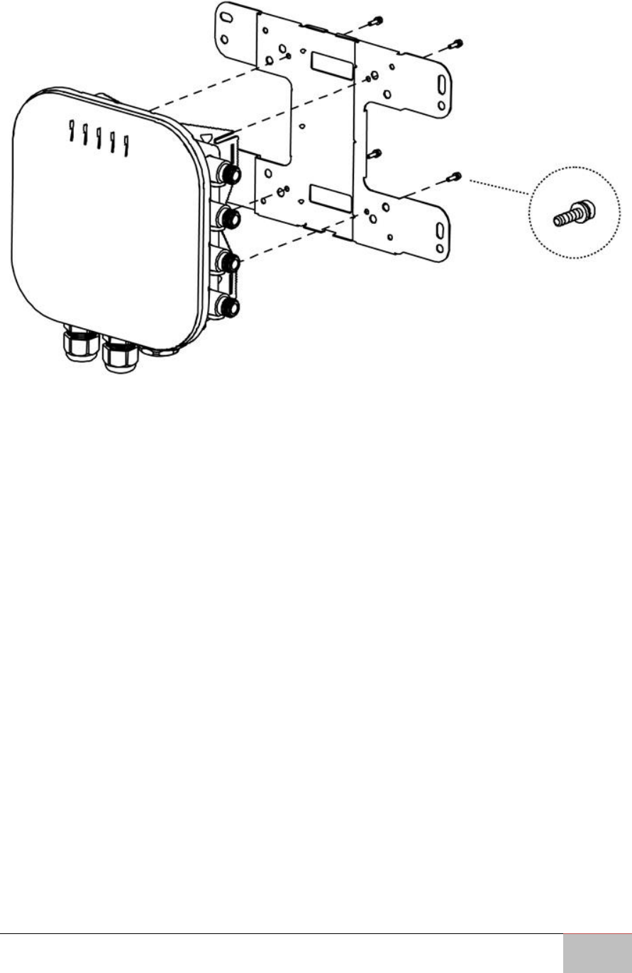
C. Place the lock and flat washers on the four hex cap screws and drive the screws
to attach the bracket to the back of the Access Point.
User Manual Chapter 3 Mounting
Outdoor Enterprise Access Point WM-OAP8251AG
26
3.2 Pole Mount the AP
To attach the WM-OAP8251AG to a wall using provided pole mounting kit:
1. Attach the device onto the wall by tightening the bolt’s flat washers and nuts to
secure the mounting base to the mounting surface.
2. Drive the four round head screws to attach the Pole Mount Bracket to a Wall
Mount bracket.
User Manual Chapter 3 Mounting
Outdoor Enterprise Access Point WM-OAP8251AG
27
3. Thread the open end of the Pole Strap through the two tabs on the Pole Mount
Bracket.
4. Lock and tighten the Pole Strap to secure the Pole Mount Bracket to the pole.
Horizontal Placement
Vertical Placement

Outdoor Enterprise Access Point WM-OAP8251AG
28
Configuring Your Access Point
This chapter describes how to configure Access
Point using the web-based configuration
interface.
Outdoor Enterprise Access Point WM-OAP8251AG
29
Chapter 4: Configuring Your Access Point
This chapter describes how to configure Access Point using the web-based configuration
interface.
Before you begin, the device must be able to communicate with the ezMaster server for
ezMaster to manage an AP or switch. Make sure that the ezMaster server, EWS AP and
EWS switch can all be reachable via HTTP/HTTPS from outside your internal network.
For more information about ezMaster server settings, refer to the user manual
“Distributed Network Management Solution”.
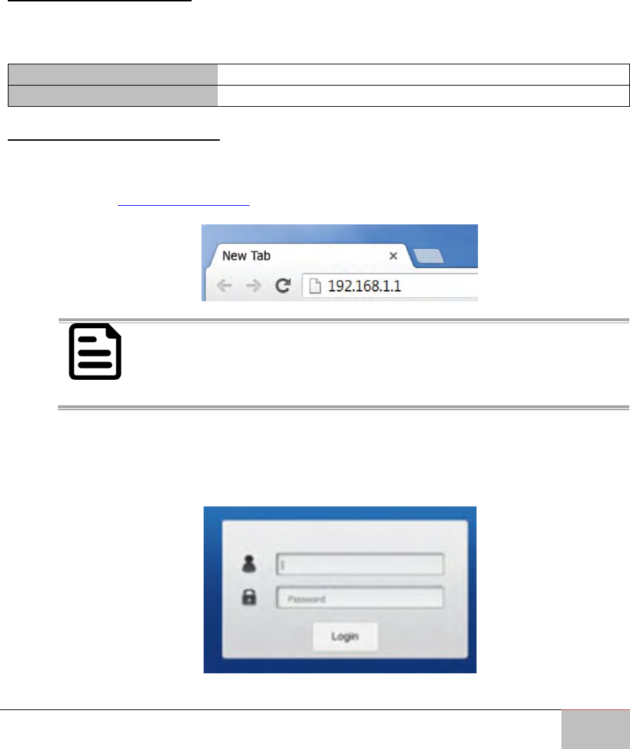
4.1 Default Settings
Please use your Ethernet port or wireless network adapter to connect the Access Point.
IP Address
192.168.1.1
User name/ password
Admin/ admin
4.2 Web Configuration
Open a web browser (Internet Explorer/Firefox/Safari/Chrome) and enter the IP
Address http://192.168.1.1.
NOTE:
If you have changed the default LAN IP Address of the Access Point,
ensure you enter the correct IP Address.
The default username and password are admin. Once you have entered the
correct username and password, click the Login button to open the web-based
configuration page.
Outdoor Enterprise Access Point WM-OAP8251AG
30
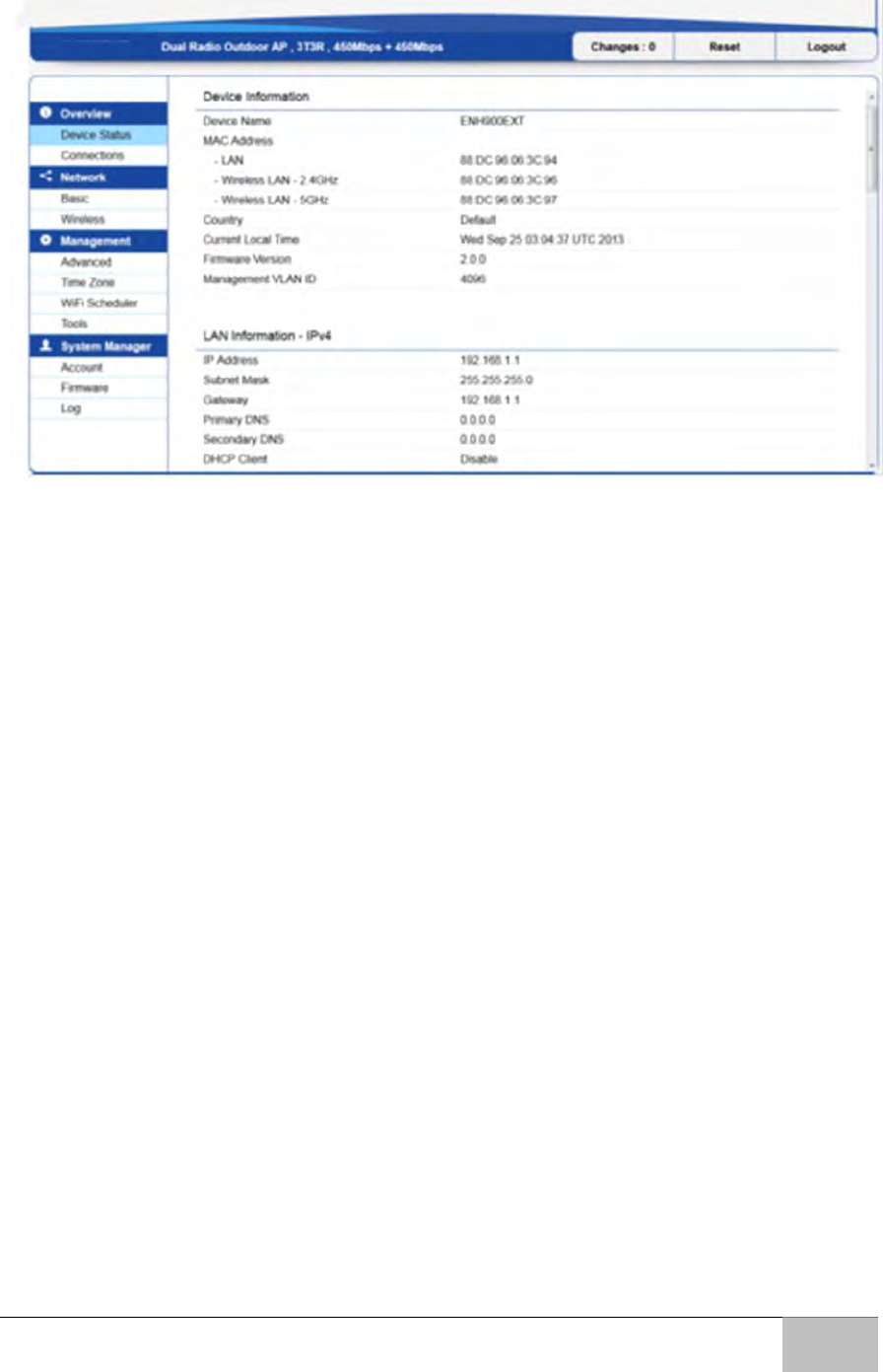
If successful, you will be logged in and see the WM-OAP8251AG User Menu.

Outdoor Enterprise Access Point WM-OAP8251AG
31
Building a Wireless Network
This chapter describes the operating modes of
the WM-OAP8251AG.
User Manual Chapter 5 Building a Wireless Network
Outdoor Enterprise Access Point WM-OAP8251AG
32
Chapter 5: Building a Wireless Network
This chapter describes the operating modes of the WM-OAP8251AG.
5.1 Access Point Mode
In Access Point Mode, WM-OAP8251AG behaves likes a central connection for stations
or clients that support IEEE 802.11ac/a/b/g/n networks. The stations and clients must be
configured to use the same SSID (Service Set Identifier) and security password to
associate with the WM-OAP8251AG. The WM-OAP8251AG supports up to eight (8) SSIDs
per band at the same time for secure access.
User Manual Chapter 5 Building a Wireless Network
Outdoor Enterprise Access Point WM-OAP8251AG
33
The WM-OAP8251AG can be used as a centralized Outdoor Access Point with which
other EnGenius Wireless N 2.4 or 5 GHz Outdoor Client Bridges can associate; leveraging
the long-range capability of their internal high-gain directional antennas, resulting in a
very cost-effective solution to expand a company network over a multiple building
campus.
User Manual Chapter 5 Building a Wireless Network
Outdoor Enterprise Access Point WM-OAP8251AG
34
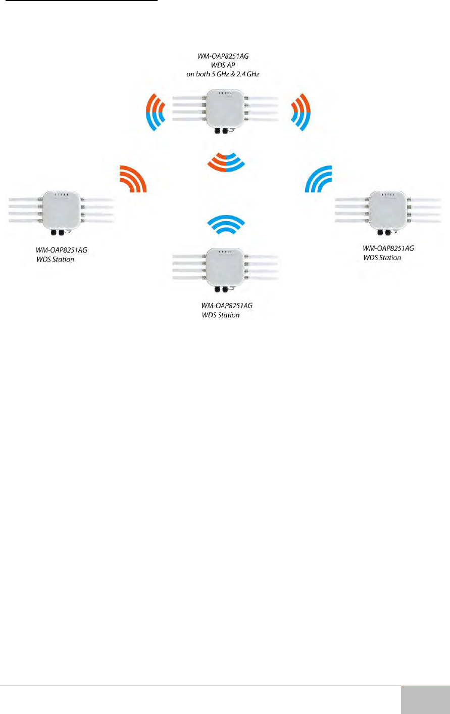
5.2 WDS AP Mode
The WM-OAP8251AG also supports WDS AP mode. This operating mode allows wireless
connections to the WM-OAP8251AG using WDS technology. In this mode, configure the
MAC addresses in both Access Points to enlarge the wireless area by enabling WDS Link
settings. WDS supports up to four (4) AP MAC adresses.
User Manual Chapter 5 Building a Wireless Network
Outdoor Enterprise Access Point WM-OAP8251AG
35
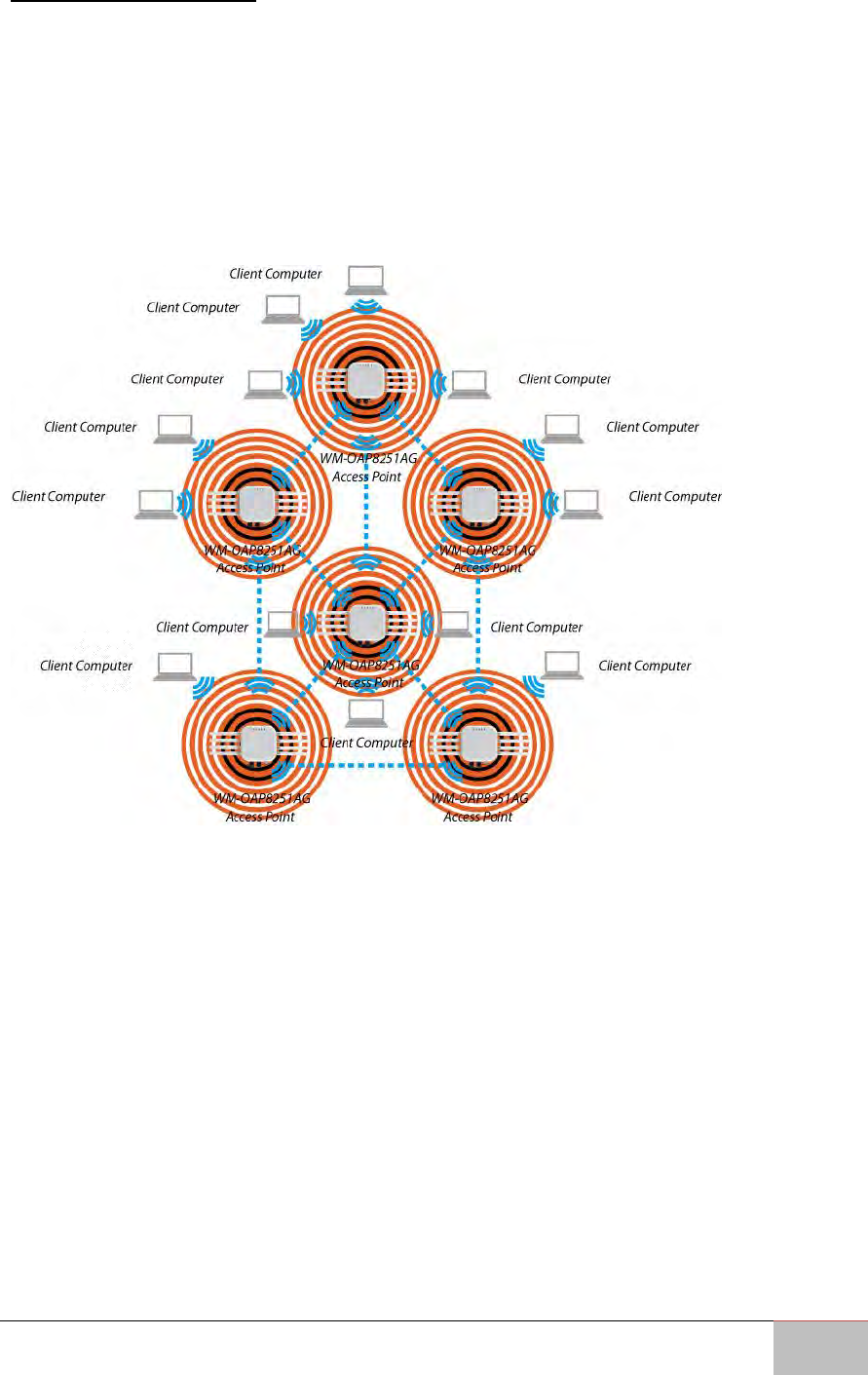
5.3 WDS Bridge Mode
In WDS Bridge Mode, the WM-OAP8251AG can wirelessly connect different LANs by
configuring the MAC address and security settings of each WM-OAP8251AG device. Use
this mode when two wired LANs located a small distance apart want to communicate
with each other. The best solution is to use the WM-OAP8251AG to wirelessly connect
two wired LANs, as shown in the following diagram. WDS Bridge Mode can establish up
to four (4) WDS links, creating a star-like network.
NOTE:
WDS Bridge Mode does not act as an Access Point. Access Points linked by
WDS are using the same frequency channel. More Access Points connected
together may lower throughput. This configuration can be susceptible to
generate endless network loops in your network, so it is recommended to
enable the Spanning Tree feature to prevent this from happening.
User Manual Chapter 5 Building a Wireless Network
Outdoor Enterprise Access Point WM-OAP8251AG
36
5.4 WDS Station Mode
Station mode expands the WDS by receiving a wireless signal/service and sharing it
through the Ethernet port.
User Manual Chapter 5 Building a Wireless Network
Outdoor Enterprise Access Point WM-OAP8251AG
37
5.5 AP Mesh Mode
Under the AP Mesh mode, the WM-OAP8251AG can be used as the central connection
hub for station or clients that support IEEE 802.11 b/g/n network. Under this mode, the
WM-OAP8251AG can be configured with the same Mesh SSID and security password in
order to associate with other WM-OAP8251AGs, as well as connect with clients under
the same SSID and encryption signatures. For example, you would use one band to
connect Access Points in range with Mesh mode and the other band to broadcast traffic
on the network.
User Manual Chapter 5 Building a Wireless Network
Outdoor Enterprise Access Point WM-OAP8251AG
38
5.6 Mesh Only Mode
Under the Mesh-only mode, the WM-OAP8251AG can be configured with the same
Mesh SSID and security password in order to associate with other Mesh enabled WM-
OAP8251AGs, instead of connecting with clients.

Outdoor Enterprise Access Point WM-OAP8251AG
39
Software Settings
This chapter describes how to set up the system.
User Manual Chapter 6 Software Settings
Outdoor Enterprise Access Point WM-OAP8251AG
40
Chapter 6: Software Settings
This chapter describes how to set up the system.
6.1 Main Status
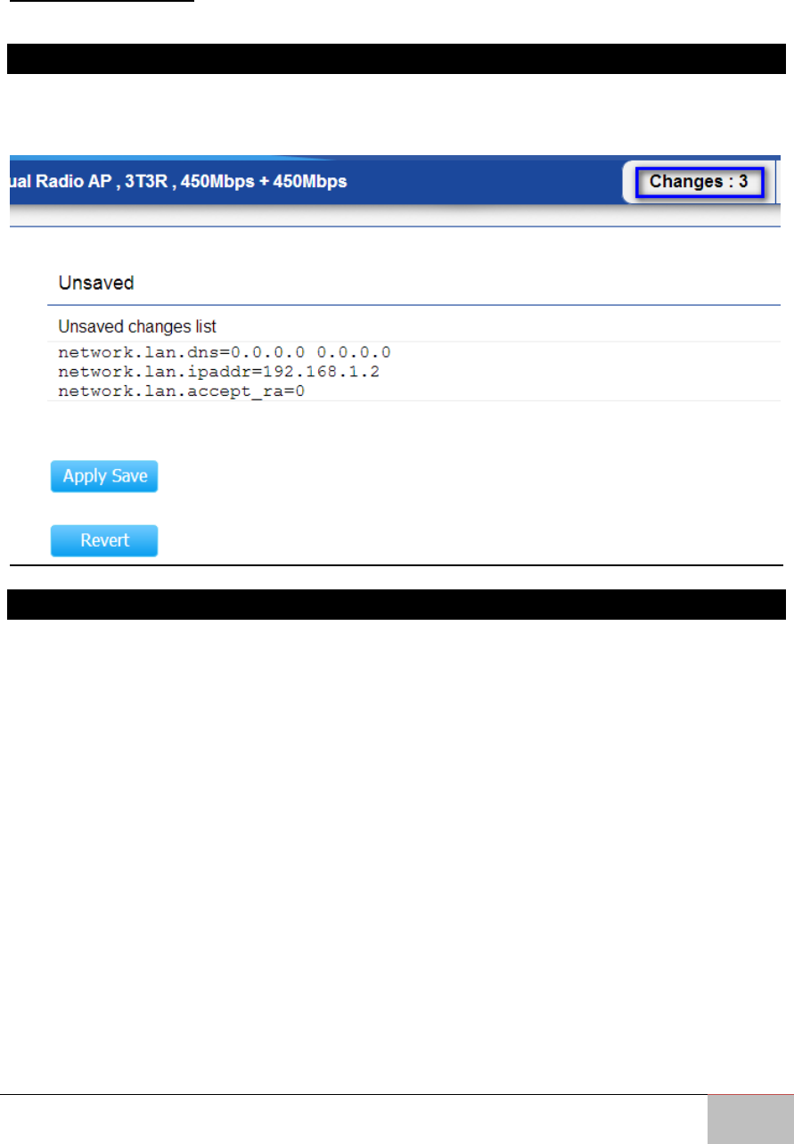
6.1.1 Save Changes
This page lets you save and apply the settings shown under Unsaved changes list, or
cancel the unsaved changes and revert to the previous settings that were in effect.
6.1.2 Device Status
Clicking the Device Status link under the Overview menu shows the status information
about the current operating mode.
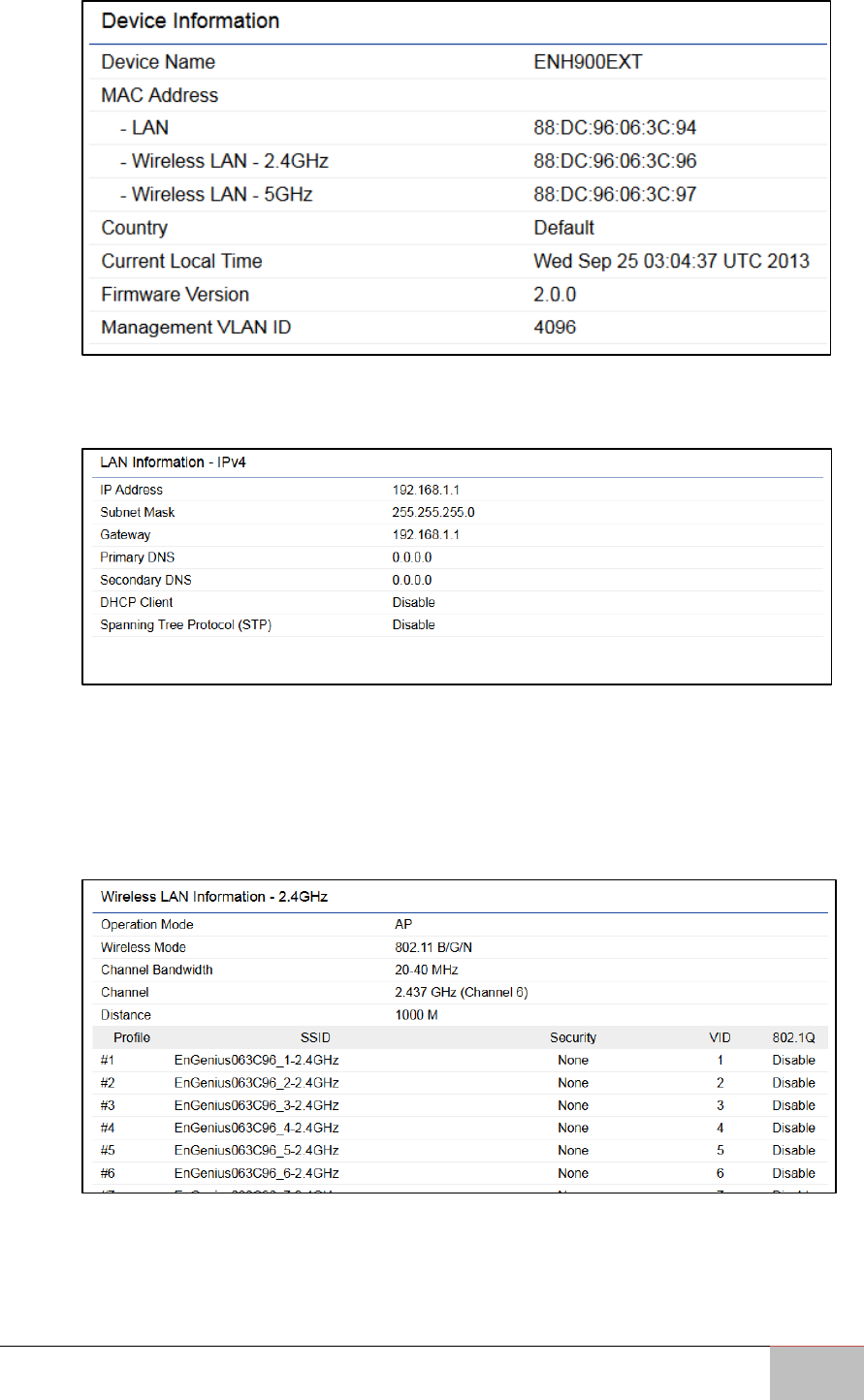
The Device Information section shows general system information such as Device
Name, MAC Address, Current Time, Firmware Version, and Management VLAN ID.
Note: VLAN ID is only applicable in Access Point or WDS AP mode.
User Manual Chapter 6 Software Settings
Outdoor Enterprise Access Point WM-OAP8251AG
41
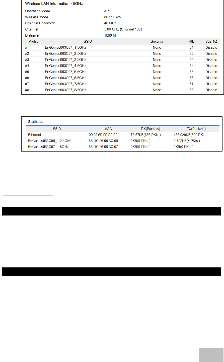
The LAN Information section shows the Local Area Network settings such as the
LAN IP Address, Subnet mask, and DNS Address.
The Wireless LAN Information 2.4 GHz/5 GHz section shows wireless information
such as Operating Mode, Frequency, and Channel. Since the ENH1750EXT
supports multiple-SSIDs, information about each SSID, the ESSID, and security
settings, are displayed.
Note: Profile Settings are only applicable in Access Point and WDS AP modes.
User Manual Chapter 6 Software Settings
Outdoor Enterprise Access Point WM-OAP8251AG
42
The Statistics section shows Mac information such as SSID, MAC address, RX and
TX.
The Wireless Mesh Information - 2.4 GHz section shows wireless information
such as Operation Mode, Wireless Mode, Channel Bandwidth,
Frequency/Channel, Mesh SSID and Mesh Security.
6.2 Connection
6.2.1 Connection List 2.4 GHz/5 GHz
Click the Connection link under the Overview tab to display the connection list of clients
associated to the ENH1750EXT’s 2.4 GHz/5 GHz bands, along with the MAC addresses
and signal strength for each client. Clicking Refresh updates the client list.
Note: Only applicable in Access Point and WDS AP modes.
6.2.2 WDS Link List2.4 GHz/5 GHz
Click the connection link under the Overview menu. This page displays the current status
of the WDS link, including WDS Link ID, MAC Address, Link Status and RSSI.
Note: Only applicable in WDS AP and WDS Bridge modes.
User Manual Chapter 6 Software Settings
Outdoor Enterprise Access Point WM-OAP8251AG
43
6.2.3 The Mesh Link List
You can monitor the 2.4GHz Mesh Link List under the Status menu. The page will display
the current status of the Mesh Links under Mesh AP mode and the Mesh nodes under
Mesh Only mode.
Note: Only applicable in the Mesh AP and Mesh Only modes.
6.3 Network
6.3.1 Basic IP Settings
6.3.1.1 IPv4/IPv6 Settings
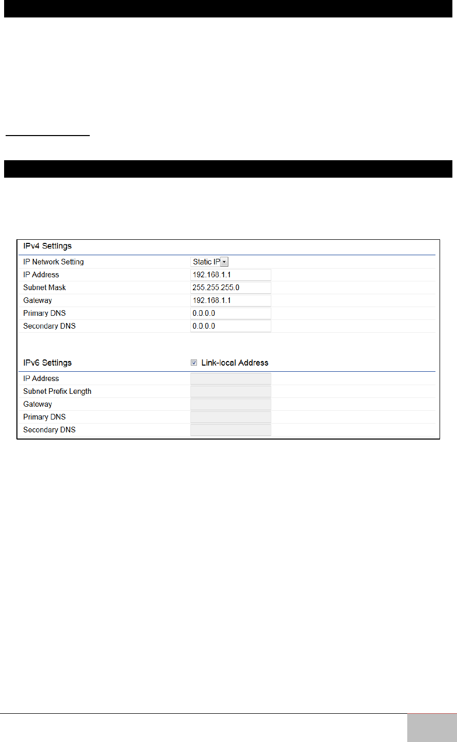
This page allows you to modify the device’s IP settings.
IP Network Settings: Select whether the device IP address will use a static IP address
specified in the IP address field or be obtained automatically when the device connects
to a DHCP server.
IP Address: Displays the IP address of this device.
Subnet Mask: Displays the IP Subnet mask of this device.
Gateway: Displays the Default Gateway of this device. Leave it blank if you are unsure of
this setting.
Primary/Secondary DNS: Displays the primary/secondary DNS address for this device.
Save: Click Save to confirm the changes.

User Manual Chapter 6 Software Settings
Outdoor Enterprise Access Point WM-OAP8251AG
44
6.3.1.2 Spanning Tree Protocol (STP) Settings
This page allows you to modify the Spanning Tree settings. Enabling the Spanning Tree
protocol will prevent network loops in your LAN network.
Spanning Tree Status: Enables or disables the Spanning Tree feature.
Hello Time: Specifies Bridge Hello Time in seconds. This value determines how often the
device sends handshake packets to communicate information about the topology
throughout the entire Bridged Local Area Network.
Max Age: Specifies Bridge Max Age in seconds. If another bridge in the spanning tree
does not send a hello packet for a long period of time, it is assumed to be inactive.
Forward Delay: Specifies Bridge Forward Delay in seconds. Forwarding delay time is the
time spent in each of the Listening and Learning states before the Forwarding state is
entered. This delay is provided so that when a new bridge comes onto a busy network, it
analyzes data traffic before participating in the network.
Priority: Specifies the Priority Number. A smaller number has a greater priority than a
larger number.
Save: Click Save to confirm the changes.
User Manual Chapter 6 Software Settings
Outdoor Enterprise Access Point WM-OAP8251AG
45
6.4 Wireless Settings
6.4.1 Wireless Settings
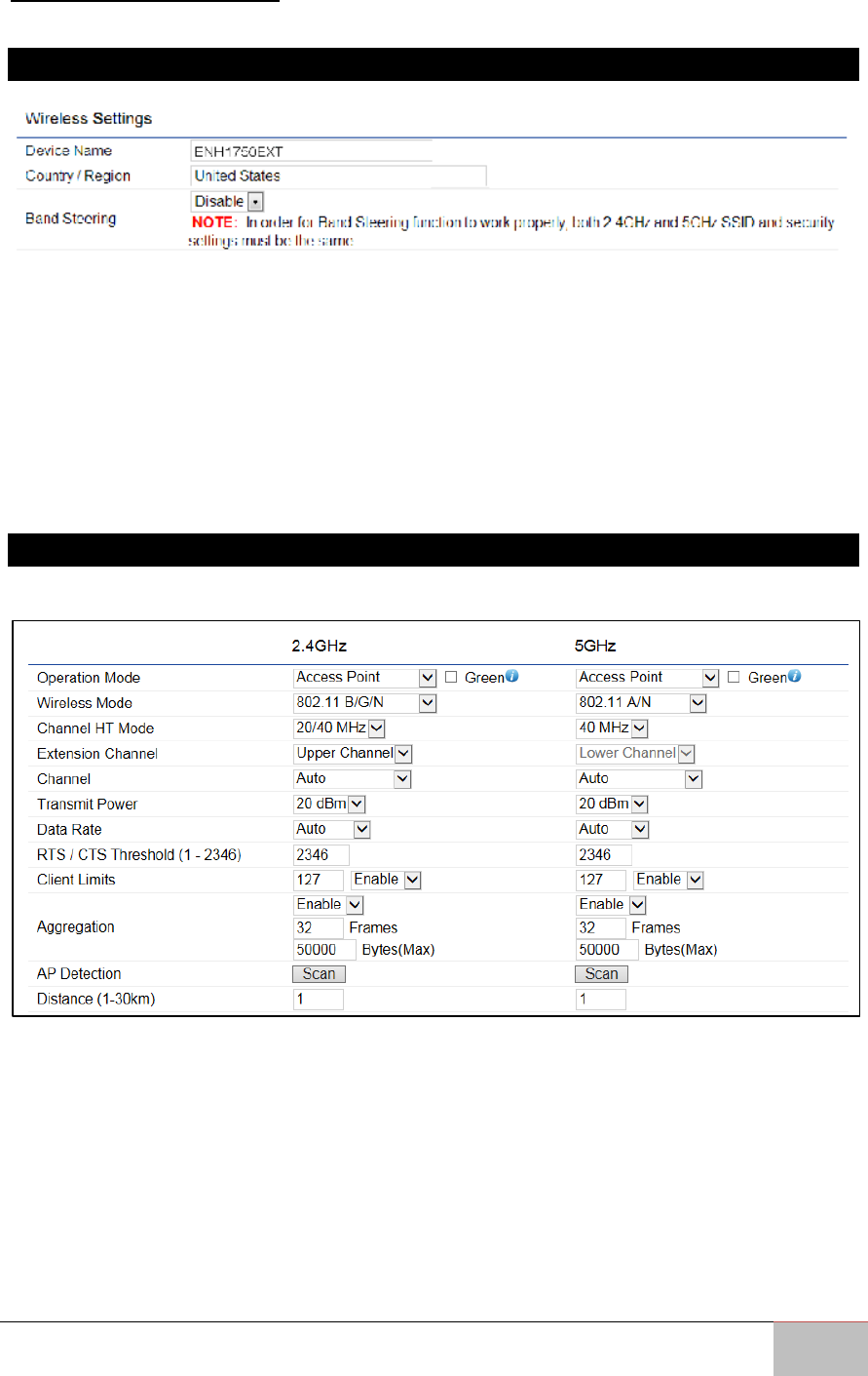
Device Name: Enter a name for the device. The name you type appears in SNMP
management. This name is not the SSID and is not broadcasted to other devices.
Band Steering: Enable Band Steering to send 802.11n clients to the 5 GHz band, where
802.11b/g clients cannot go, and leave 802.11b/g clients in 2.4 GHz band to maintain
optimal data traffic flow. Band Steering works within the Access Point by directing 5
GHz-capable clients to that band.
Save: Click Save to confirm the changes.
6.4.2 Wireless Network 2.4 GHz/5 GHz
This page displays the current status of the Wireless settings of the WM-OAP8251AG.

User Manual Chapter 6 Software Settings
Outdoor Enterprise Access Point WM-OAP8251AG
46
Operation Mode: Select Operation Mode. The WM-OAP8251AG supports two different
operation modes: Access Point, or WDS (WDS AP, WDS Bridge, and WDS Station).
Wireless Mode: Supports 802.11b/g/n mixed mode in 2.4 GHz and 802.11ac/a/n mixed
mode in 5 GHz.
Channel HT Mode: The default channel bandwidth is 20 MHz/40 MHz. The larger the
channel, the greater the transmission quality and speed.
Extension Channel: Select the upper or lower channel. Your selection may affect the
Auto channel feature.
Transmit Power: Sets the power output of the wireless signal.
Data Rate: Select a data rate from the drop-down list. The data rate affects throughput
of data in the WM-OAP8251AG. Select the best balance for you and your network but
note that the lower the data rate, the lower the throughput, though transmission
distance is also lowered.
RTS/CTS Threshold: Specifies the threshold package size for RTC/CTS. A smaller number
causes RTS/CTS packets to be sent more often and consumes more bandwidth.
Client Limits: Limits the total number of clients.
Aggregation: Merges data packets into one packet. This option reduces the number of
packets, but also increases packet sizes.
AP Detection: The AP Detection feature can select the best channel to use by scanning
nearby areas for Access Points.
Distance: Specifies the distance between Access Points and clients. Note that longer
distances may drop higher- speed connections.
Save: Click Save to confirm the changes or Cancel to cancel and return to previous
settings.
User Manual Chapter 6 Software Settings
Outdoor Enterprise Access Point WM-OAP8251AG
47
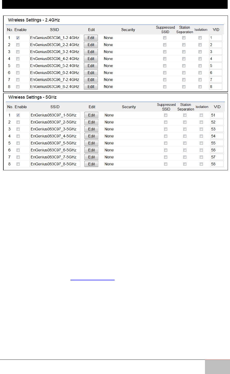
6.4.3 SSID Profiles 2.4 GHz/5 GHz
Current Profile: You can configure up to sixteen (16)different SSIDs (eight (8) per band).
If multiple client devices will be accessing the network, you can arrange the devices into
SSID groups. Click Edit to configure the profile and check whether you wish to enable
extra SSIDs.
SSID: Specifies the SSID for the current profile.
Suppressed SSID: Check this option to hide a SSID from clients. If checked, the SSID will
not appear in the site survey.
Station Separation: Check the box to allow or prevent communication between client
devices.
VID: Specifies the VLAN tag for each profile. If your network includes VLANs, you can
specify a VLAN ID for packets to pass through the Access Point with a tag.
Wireless Security: See the Wireless Security section.
Isolation: Check the box to restrict clients from communicating with different VIDs.
Save: Click Save to accept the changes.
User Manual Chapter 6 Software Settings
Outdoor Enterprise Access Point WM-OAP8251AG
48
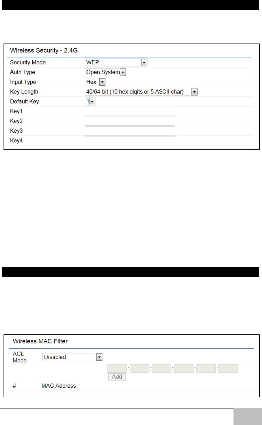
6.4.4 Wireless Security
The Wireless Security section lets you configure the WM-OAP8251AG’s security modes:
WEP, WPA-PSK, WPA2-PSK, WPA-PSK Mixed, WPA, WPA2, and WPA Mixed. It is strongly
recommend that you use WPA2-PSK.
Auth Type: Select Open System or Shared Key.
Input Type:
• ASCII: Regular Text (recommended)
• Hexadecimal Numbers (For advanced users)
Key Length: Select the desired option and ensure that wireless clients use the same
setting. Your choices are 64, 128, and 152-bit password lengths.
Default Key: Select the Key you wish to be the default value. Transmitted data is
ALWAYS encrypted using the Default Key; the other Keys are for decryption only. You
must enter a Key Value for the Default Key.
Encryption Key Number: Enter the Key Value or values you wish to use. Only the Key
selected as Default is required. The others are optional.
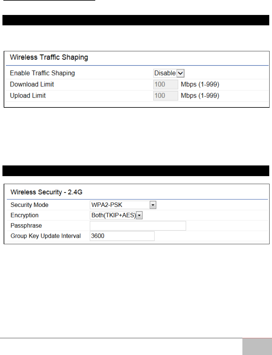
6.4.5 Wireless MAC Filtering
Wireless MAC Filtering is used to allow or deny network access to wireless clients
(computers, tablet PCs, NAS, smartphones, etc.) according to their MAC addresses. You
can manually add a MAC address to restrict permission to access the ENH1750EXT. The
default setting is: Disable Wireless MAC Filter.
Note: Only applicable in Access Point and WDS AP modes.
User Manual Chapter 6 Software Settings
Outdoor Enterprise Access Point WM-OAP8251AG
49
ACL Mode: Determines whether network access is granted or denied to clients whose
MAC addresses appear in the MAC address table on this page. Your choices are: Disabled,
Deny MAC in the list, or Allow MAC in the list.
MAC Address: Enter the MAC address of the wireless client.
Add: Click Add to add the MAC address to the MAC address table.
Delete: Deletes the selected entries.
Save: Click Save to apply the changes.
6.5 Wireless Advanced
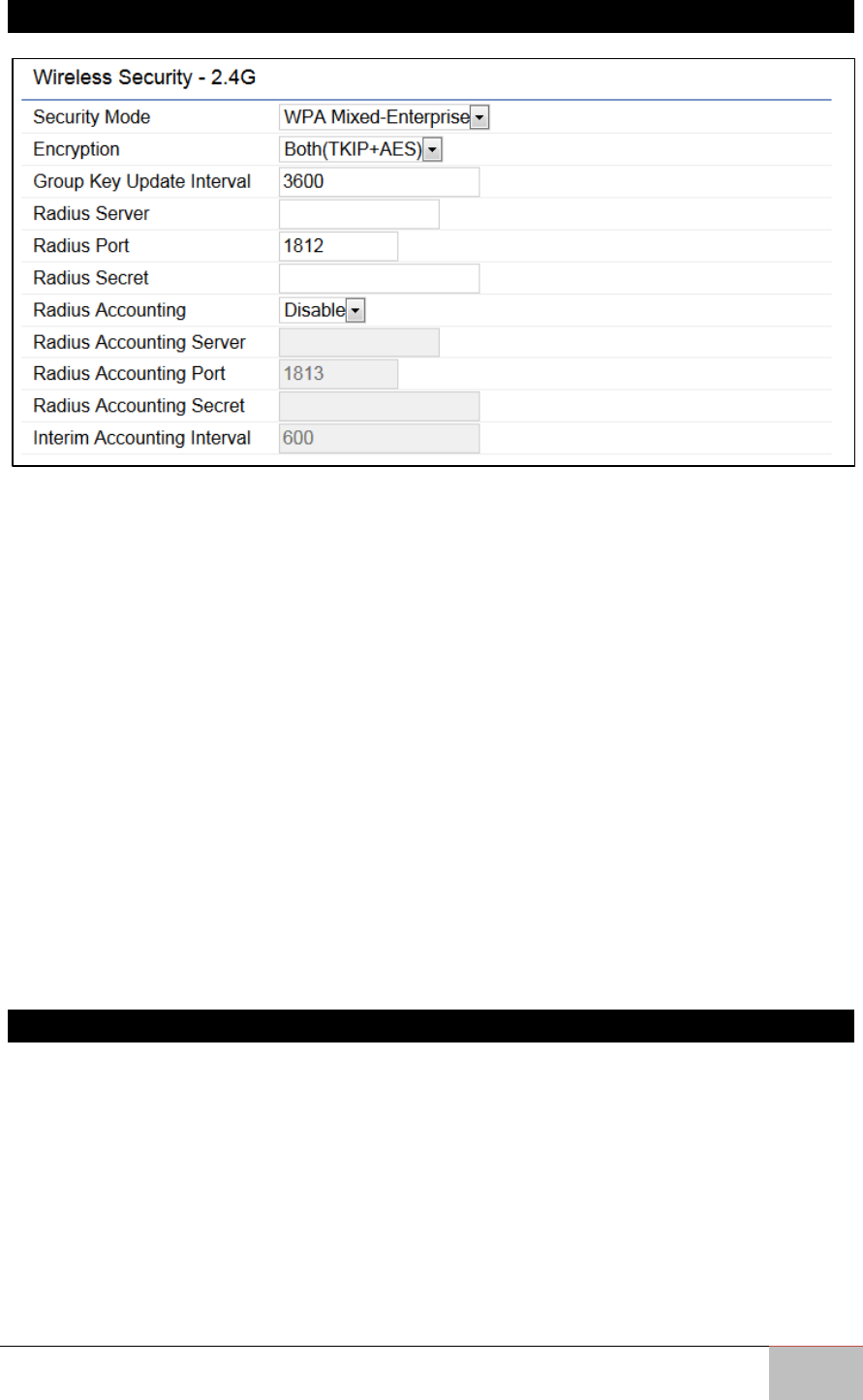
6.5.1 Wireless Traffic Shaping
Traffic shaping regulates the flow of packets leaving an interface to deliver improved
Quality of Service.
Enable Traffic Shaping: Check this option to enable Wireless Traffic Shaping.
Download Limit: Specifies the wireless transmission speed used for downloading.
Upload Limit: Specifies the wireless transmission speed used for uploading.
Save: Click Save to confirm the changes.
6.5.2 WPA-PSK (WPA Pre-Shared Key) Encryption
Encryption: Select the WPA encryption type you would like to use. Please ensure that
your wireless clients use the same settings.
Passphrase: Wireless clients must use the same Key to associate the device. If using
ASCII format, the Key must be from 8~63 characters in length. If using HEX format, the
Key must be 64 HEX characters in length.
Group Key Update Interval: Specifies how often, in seconds, the Group Key changes.
User Manual Chapter 6 Software Settings
Outdoor Enterprise Access Point WM-OAP8251AG
50
6.5.3 WPA Mixed-Enterprise: Access Point / WDS AP Mode
Encryption: Select the WPA encryption type you would like to use. Please ensure that
your wireless clients use the same settings.
Radius Server: Enter the IP address of the Radius server.
Radius Port: Enter the port number used for connections to the Radius server.
Radius Secret: Enter the secret required to connect to the Radius server.
Group Key Update Interval: Specifies how often, in seconds, the Group Key changes.
Radius Accounting: Enables or disables the accounting feature.
Radius Accounting Server: Enter the IP address of the Radius accounting server. Radius
Accounting Port Enter the port number used for connections to the Radius accounting
server.
Radius Accounting Secret: Enter the secret required to connect to the Radius accounting
server.
Interim Accounting Interval: Specifies how often, in seconds, the accounting data sends.
Note: 802.11n does not allow WEP/WPA-PSK TKIP/WPA2-PSK TKIP security mode.
The connection mode will automatically change from 802.11n to 802.11g.
6.5.4 Fast Roaming
Enable this feature to serve mobile client devices that roam from Access Point to Access
Point. Some applications running on client devices require fast re-association when they
roam to a different Access Point
Please enter the settings of the SSID and initialize the Security mode to WPA Enterprise,
as well as setting the Radius Server. Users can then enable Fast Roaming and implement
the advanced search feature.
Next, set the same Enterprise Encryption with the same SSID on other Access Points in
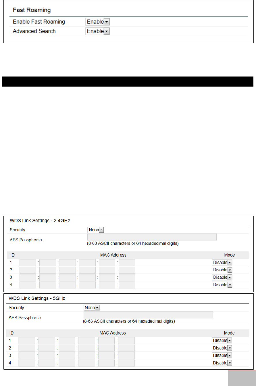
User Manual Chapter 6 Software Settings
Outdoor Enterprise Access Point WM-OAP8251AG
51
the network and enable Fast Roaming. When the configuration is set on all the Access
Points on the network, mobile client devices can run voice services that require fast
roaming to prevent delay in conversation from Access Point to Access Point.
Enable Fast Roaming: Enables or disables the Fast Roaming feature.
Enable Advanced Search: Enables or disables the Advanced Search feature.
6.5.5 WDS Link Settings
Using the WDS (Wireless Distribution System) feature will allow a network administrator
or installer to connect to Access Points wirelessly. Doing so will extend the wired
infrastructure to locations where cabling is not possible or inefficient to implement.
Note: Compatibility between different brands and models of Access Points is not
guaranteed. It is recommended that the WDS network be created using the same
models for maximum compatibility.
Also note: All Access Points in the WDS network need to use the same Channel
and Security settings.
To create a WDS network, please enter the MAC addresses of the Access Points that you
want included in the WDS. There can be a maximum of four (4) Access Points.
Note: Only applicable in WDS AP and WDS Bridge modes.
6.5.5.1 WDS Link Settings 2.4 GHz/5 GHz
User Manual Chapter 6 Software Settings
Outdoor Enterprise Access Point WM-OAP8251AG
52
Security: Select None or AES from the drop-down list.
AES Passphrase: Enter the Key Values you wish to use. Other Access Points must use the
same Key to establish a WDS link.
MAC Address: Enter the Access Point’s MAC address to where you want to extend the
wireless area.
Mode: Select to disable or enable from the drop-down list.
Save: Click Save to confirm the changes.
6.5.5.2 Mesh Link Settings 2.4 GHz
Users can choose the 2.4 GHz band for Mesh Mode.
Mesh Settings
Mesh SSID: To create a Mesh network, please enter the Mesh SSID of the Access Point
that you wish to include in the Mesh network.
Security: Select None or WPA2-PSK AES from drop-down list.
AES Passphrase: Enter the Key Values you wish to use. Other Access Points must use the
same Key to establish a Mesh Link.
Guest Network Settings
Adding a guest network allows visitors to use the Internet without giving out your office
or company wireless security key. You can add a guest network to each wireless network
for both the 2.4 GHz and 5 GHz frequency bands.
User Manual Chapter 6 Software Settings
Outdoor Enterprise Access Point WM-OAP8251AG
53
SSID: Specifies the SSID for the current profile.
Suppressed SSID: Check this option to hide the selected SSID from clients. If checked,
the SSID will not appear in the site survey.
Station Separation: Check the box to allow or prevent communication between client
devices.
IP Address: Displays the IP address of this device.
Subnet Mask: Displays the IP Subnet mask of this device.
Starting IP Address: The first IP Address in the range of the addresses used by the DHCP
server.
Ending IP Address: The last IP Address in the range of addresses assigned by the DHCP
server.
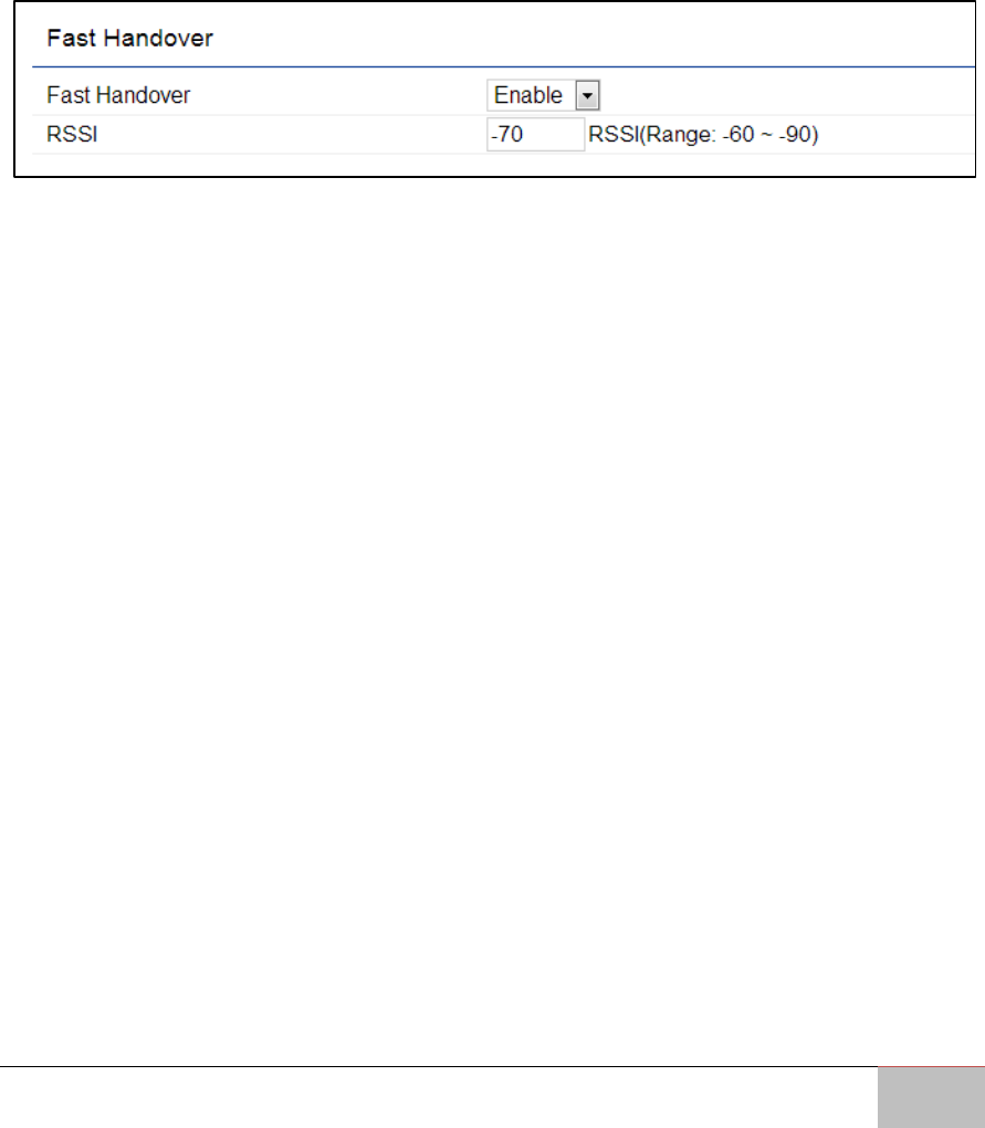
Fast Handover
Fast Handover: Enable the Fast Handover feature by ensuring that each client is served
by at least one Access Point at any time. Access Points continuously monitor the
connectivity quality of any client in their range and efficiently share this information with
other Access Points in the vicinity of that client to coordinate which of them should
serve the client best.
RSSI: Enter the RSSI (Received Signal Strength Index) in order to determine the handover
procedure which the current wireless link will terminate. RSSI is an indication of the
power level being received by the antenna. Therefore, the higher the RSSI number, the
stronger the signal.

Outdoor Enterprise Access Point WM-OAP8251AG
54
Management
This chapter describes how to manage Access
Point settings.

User Manual Chapter 7 Management
Outdoor Enterprise Access Point WM-OAP8251AG
55
Chapter 7: Management
This chapter describes how to manage Access Point settings.
7.1 Management VLAN Settings
This page allows you to assign a VLAN tag to packets sent over the network. A VLAN is a
group of computers on a network whose software has been configured so that they
behave as if they were on a separate Local Area Network (LAN). Computers on VLAN do
not have to be physically located next to one another on the LAN.
Note: Only applicable in Access Point and WDS AP modes.
Management VLAN: If your network includes VLANs, you can enable the Management
VLAN ID setting for packets passing through the Access Point with a tag.
Save: Click Save to confirm the changes or Cancel to cancel and return to previous
settings.
Note: If you reconfigure the Management VLAN ID, you may lose your
connection to the WM-OAP8251AG. Verify that the DHCP server supports the
reconfigured VLAN ID and then reconnect to the WM-OAP8251AG using the new
IP address.
7.2 Advanced Settings
7.2.1 SNMP Settings
This page allows you to assign the Contact Details, Location, Community Name, and Trap
Settings for a Simple Network Management Protocol (SNMP). SNMP is a networking
management protocol used to monitor network attached devices. SNMP allows
messages (called protocol data units) to be sent to various parts of the network. Upon
receiving these messages, SNMP compatible devices (called agents) return the data
stored in their Management Information Bases.

User Manual Chapter 7 Management
Outdoor Enterprise Access Point WM-OAP8251AG
56
SNMP Enable/Disable: Enables or disables the SNMP feature.
Contact: Specifies the contact details of the device.
Location: Specifies the location of the device.
Community Name (Read Only): Specifies the password for the SNMP community for
read only access.
Community Name (Read/Write): Specifies the password for the SNMP community with
read/write access.
Trap Destination Address: Specifies the IP address of the computer that will receive the
SNMP traps.
Trap Destination Community Name: Specifies the password for the SNMP trap
community.
SNMPv3: Enables or disables the SNMPv3 feature.
User Name: Specifies the username for SNMPv3.
Auth Protocol: Selects the authentication protocol type: MDS or SHA.
Auth Key: Specifies the authentication key.
Priv Protocol: Selects the privacy protocol type: DES.
Priv Key: Specifies the privacy key.
Engine ID: Specifies the engine ID for SNMPv3.
Apply Save: Click Apply Save to apply the changes.
User Manual Chapter 7 Management
Outdoor Enterprise Access Point WM-OAP8251AG
57
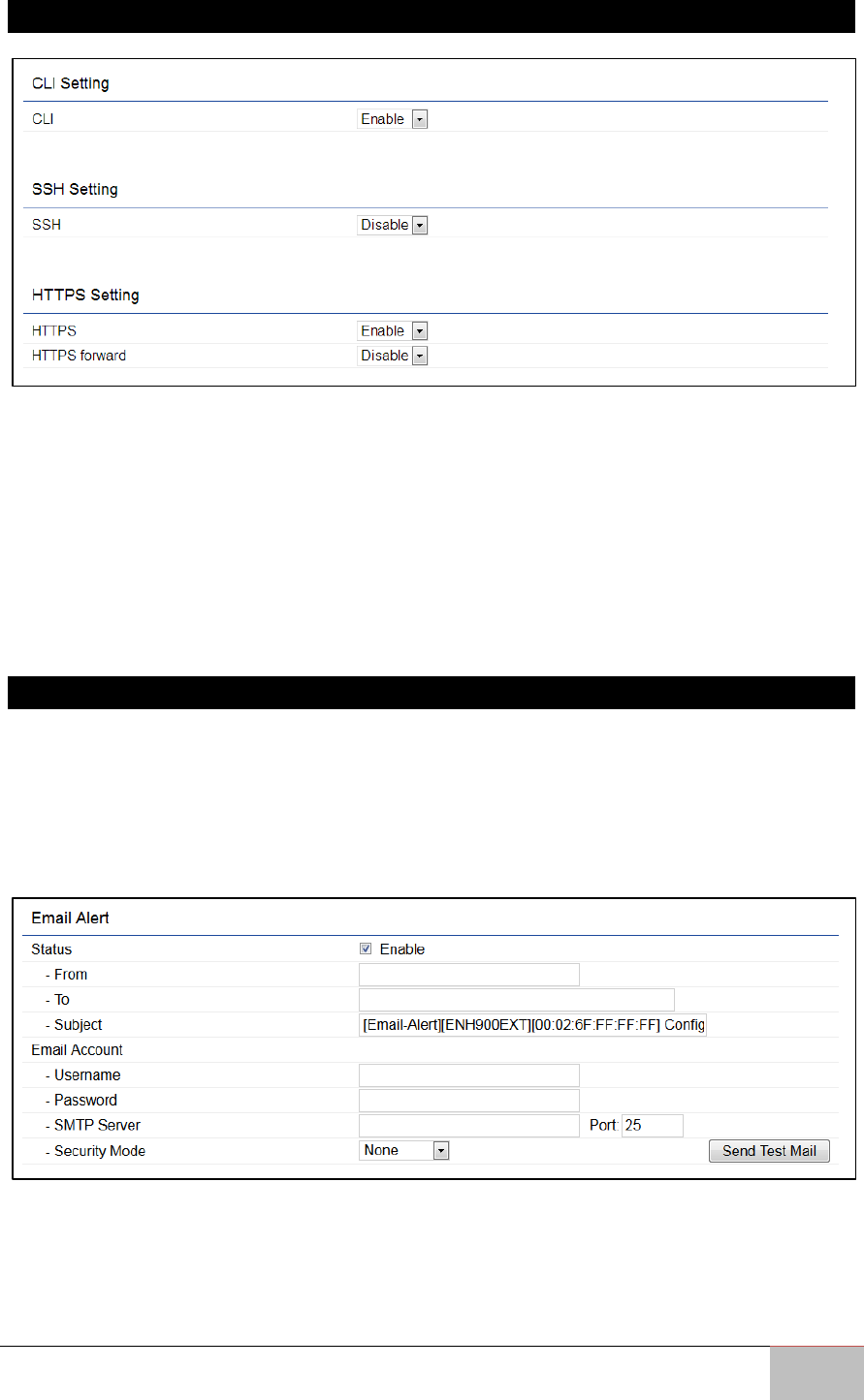
7.2.2 CLI Settings
CLI: The Command Line Interface (CLI) allows you to type commands instead of choosing
them from a menu or selecting an icon to perform an action.
SSH: Enable Secure Shell (SSH) to make secure, encrypted connections in the network.
Secure Shell is a network protocol that allows data to be exchanged using a secure
channel between two network devices.
HTTPS: Enable HTTPS to transfer and display web content securely. The Hypertext
Transfer Protocol over SSL (Secure Socket Layer) is a TCP/IP protocol used by web
servers to transfer and display web content securely.
7.2.3 Email Alerts
You can use the Email Alert feature to send messages to the configured email address
when particular system events occur.
Note: Do NOT use your personal email address as it can unnecessarily expose
your personal email login credentials. Use a separate email account made for this
feature instead.
From: Enter the email address to show the sender of the email.
To: Enter the address to receive email alerts.
Subject: Enter the text to appear in the email subject line.
Username: Enter the username for the email account that will be used to send emails.
Password: Enter the password for the email account that will be used to send emails.
User Manual Chapter 7 Management
Outdoor Enterprise Access Point WM-OAP8251AG
58
SMTP Server: Enter the IP address or hostname of the outgoing SMTP server.
Port: Enter the SMTP port number to use for outbound emails.
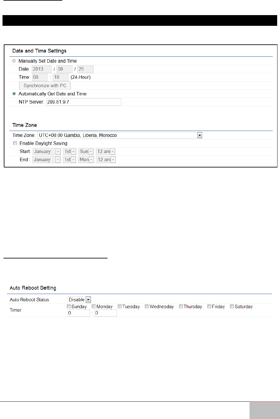
7.3 Time Zone
7.3.1 Time Setting
This page allows you to set the internal clock of the WM-OAP8251AG.
Manually Set Date and Time: Manually specify the date and time.
Automatically Get Date and Time: Select this option and enter the IP address of an NTP
server or use the default NTP server to have the internal clock synch automatically.
Enable Daylight Saving: Check whether daylight savings applies to your area. If you
select this option, you will need to enter start and stop times.
Start: Select the day, month, and time when daylight savings time starts in your region.
End: Select the day, month, and time when daylight savings times ends in your region.
7.4 Auto Reboot Settings
You can specify how often you wish to reboot the WM-OAP8251AG.
Auto Reboot Setting: Enables or disables the Auto Reboot feature.
Frequency of Auto Reboot: Specifies how often you wish to reboot the ENH1750EXT by
Min, Hour, Day or Week.
Timer: Select the day and enter the time you would like to reboot automatically.
Save: Click Save to apply the changes.
User Manual Chapter 7 Management
Outdoor Enterprise Access Point WM-OAP8251AG
59
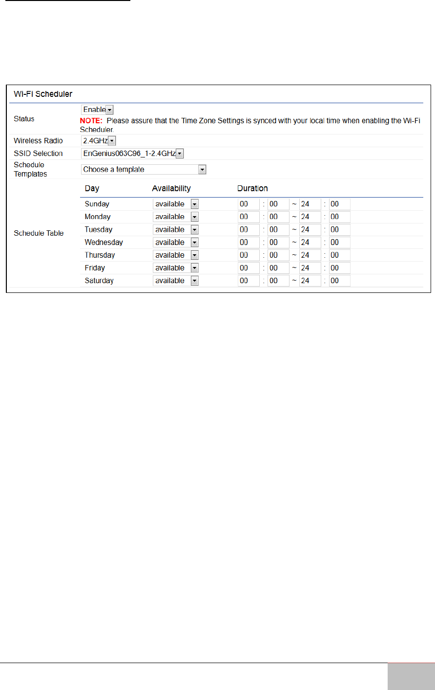
7.5 Wi-Fi Scheduler
The Wi-Fi Scheduler can be created for use in enforcing rules. For example, if you wish to
restrict web access to Mon-Fri from 3pm to 8pm, you could create a schedule selecting
Mon, Tue, Wed, Thu and Fri while entering a Start time of 3pm and an End Time of 8pm
to limit access to these times.
Status: Enables or disables the Wi-Fi scheduler feature.
Wireless Radio: Select 2.4 GHz or 5 GHz from the drop- down list for the preferred band
type that you wish to be regulated.
SSID Selection: Select a SSID from the drop-down list to be regulated.
Schedule Templates: Select a schedule template from the drop-down list.
Day(s): Place a checkmark in the boxes for the desired days or select the All Week from
the drop-down list to select all seven days of the week.
Duration: The Start Time is entered in two fields. The first box is for hours and the
second box is for minutes. The End Time is entered in the same format as the Start time.
User Manual Chapter 7 Management
Outdoor Enterprise Access Point WM-OAP8251AG
60
7.6 Tools
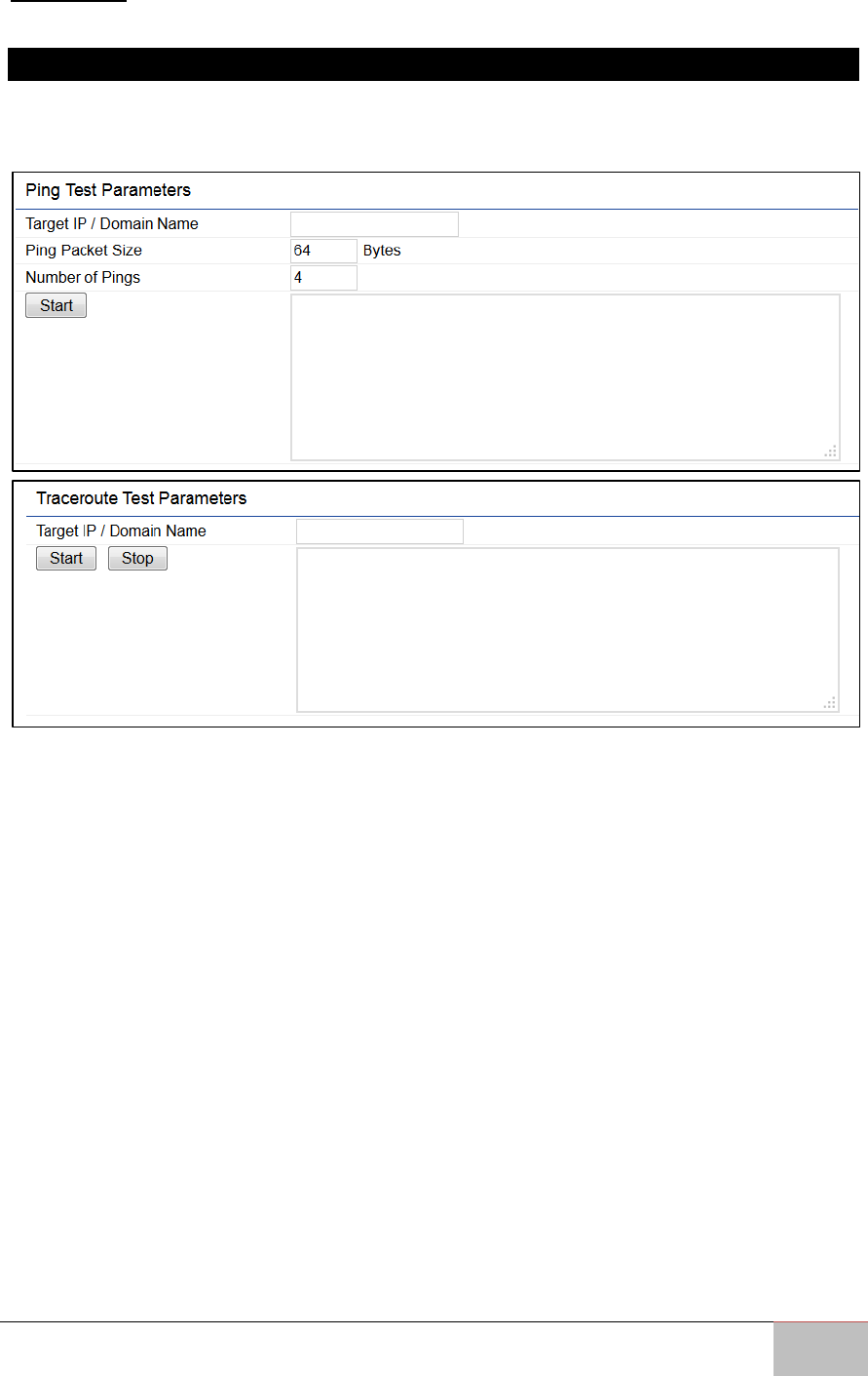
7.6.1 Ping Test Parameters
This page allows you to analyze the connection quality of the WM-OAP8251AG and trace
the routing table to a target in the network in the event of an issue.
Target IP: Enter the IP address you would like to test.
Ping Packet Size: Enter the packet size of each ping.
Number of Pings: Enter the number of times you wish to ping.
Start Ping: Click Start Ping to begin the ping test.
Traceroute Target: Enter the IP address or domain name you wish to trace.
Start Traceroute: Click Start Traceroute to begin the trace route operation.
User Manual Chapter 7 Management
Outdoor Enterprise Access Point WM-OAP8251AG
61
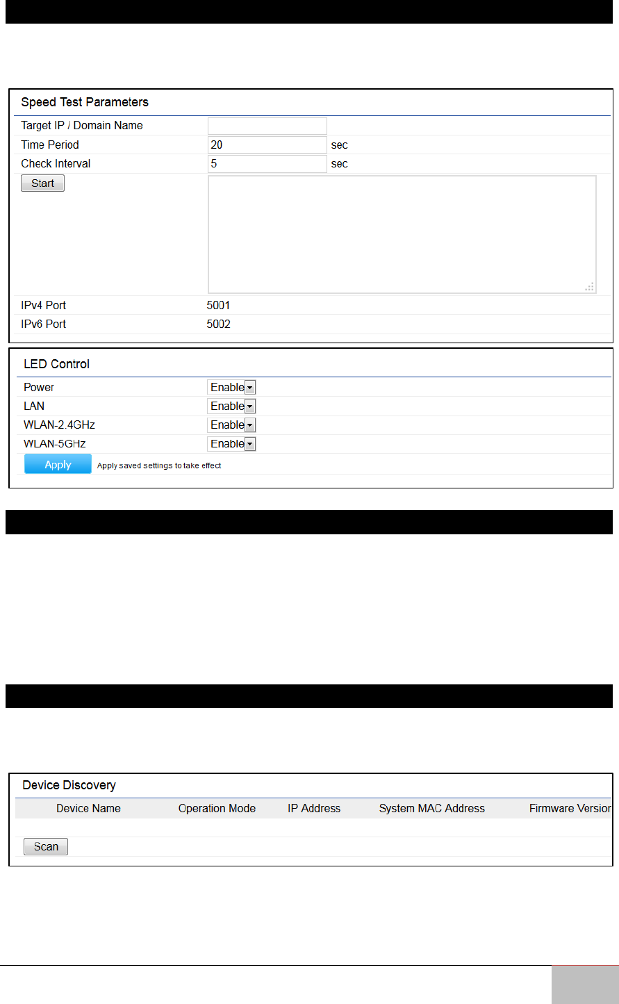
7.6.2 Speed Test Parameters/LED Control
This page allows you to power on/off the LEDs for Power, LAN interface, or 2.4 GHz/5
GHz WLAN interface for the WM-OAP8251AG.
7.6.3 LED Control
Power: Enables or disables the Power LED indicator.
LAN: Enables or disables the LAN LED indicator.
WLAN-2.4 GHz: Enables or disables the WLAN 2.4 GHz LED indicator.
WLAN-5 GHz: Enables or disables the WLAN 5 GHz LED indicator.
Device Discovery
7.6.4 Device Discovery
This page allows you to discover devices on the network and displays their: Operation
Mode, IP Address, System MAC Address and Firmware version.

User Manual Chapter 7 Management
Outdoor Enterprise Access Point WM-OAP8251AG
62
7.7 Account
This page allows you to change the WM-OAP8251AG username and password. By
default, the username is: admin and the password is: admin. The password can contain
from 0~12 alphanumeric characters and is case sensitive.
7.7.1 Account Settings
Administrator Username: Enter a new username for logging in into the New Name entry
field.
Current Password: Enter the old password for logging in into the Old Password entry
field.
New Password: Enter the new password for logging in into the New Password entry field.
Verify Password: Re-enter the new password in the Confirm Password entry field for
confirmation.
Apply: Click Apply to apply the changes.
User Manual Chapter 7 Management
Outdoor Enterprise Access Point WM-OAP8251AG
63
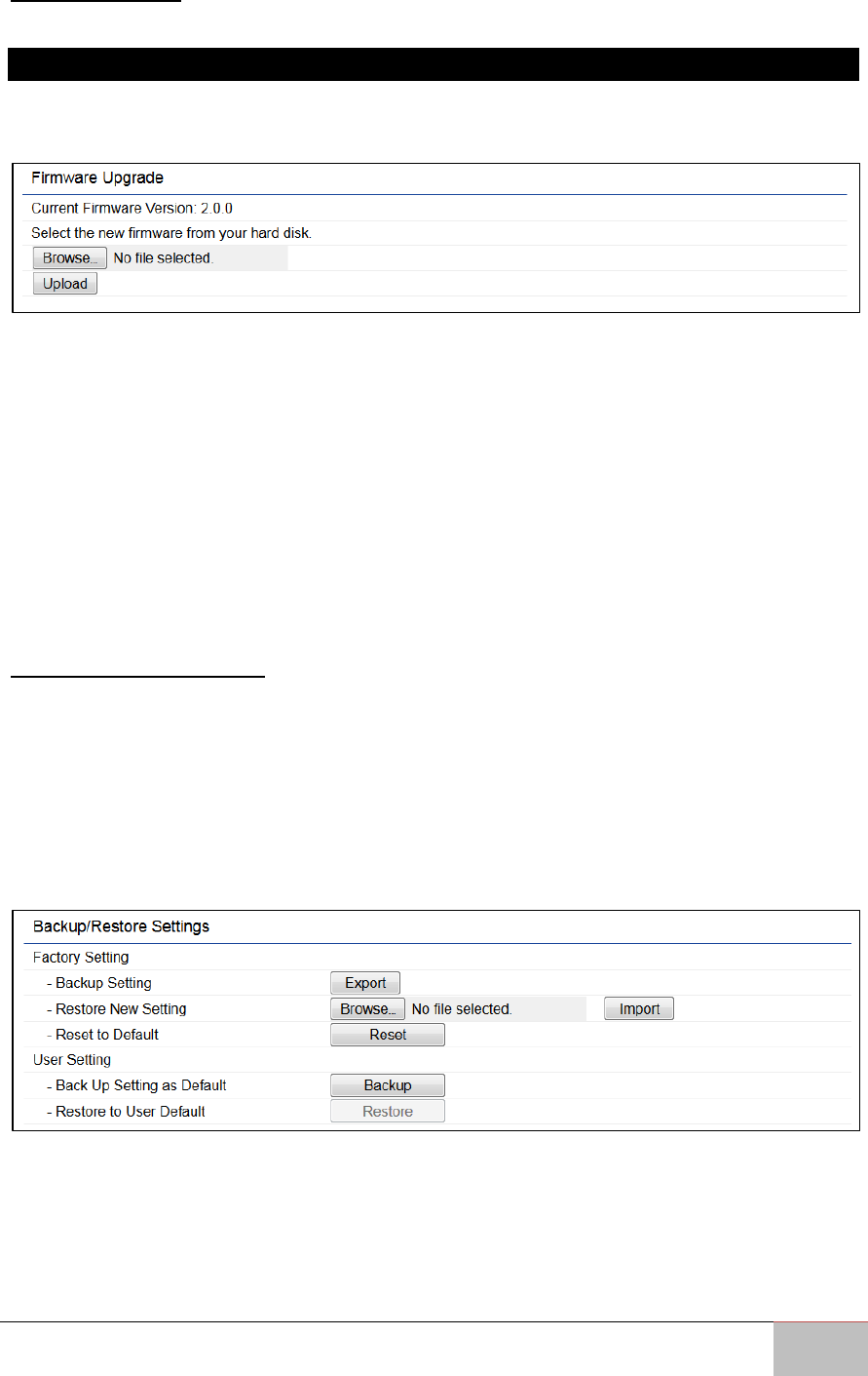
7.8 Firmware
7.8.1 Firmware Upgrade
This page allows you to upgrade the firmware of the WM-OAP8251AG. Download the
latest firmware from engeniustech.com and save it to your computer.
To Perform the Firmware Upgrade:
1. Click the Choose File button and find the firmware file you downloaded from
engeniustech.com.
2. Select the upgrade file. The name of the file will appear in the Upgrade File field.
3. Click the Upload button to commence the firmware upgrade.
Note: The device is unavailable during the Firmware upgrade process and must
restart when the upgrade is completed. Any connections to or through the device
will be lost.
7.9 Backup/Restore
This page allows you to save the current device configurations. When you save your
configurations, you also can reload the saved configurations into the device through the
Restore Saved Settings from a file saved on your computer. If extreme problems occur,
or if you have set the WM-OAP8251AG incorrectly, you can use the Reset button in the
Revert to Factory Default Settings section to restore all the configurations of the WM-
OAP8251AG to the original default settings.
Backup Setting: Click Export to save the current configured settings.
Restore New Setting: To restore settings that have been previously backed up, click
Browse, select the file, and click Restore.
Restore to User Default: Click Reset button to restore the WM-OAP8251AG to its factory
default settings.
User Manual Chapter 7 Management
Outdoor Enterprise Access Point WM-OAP8251AG
64
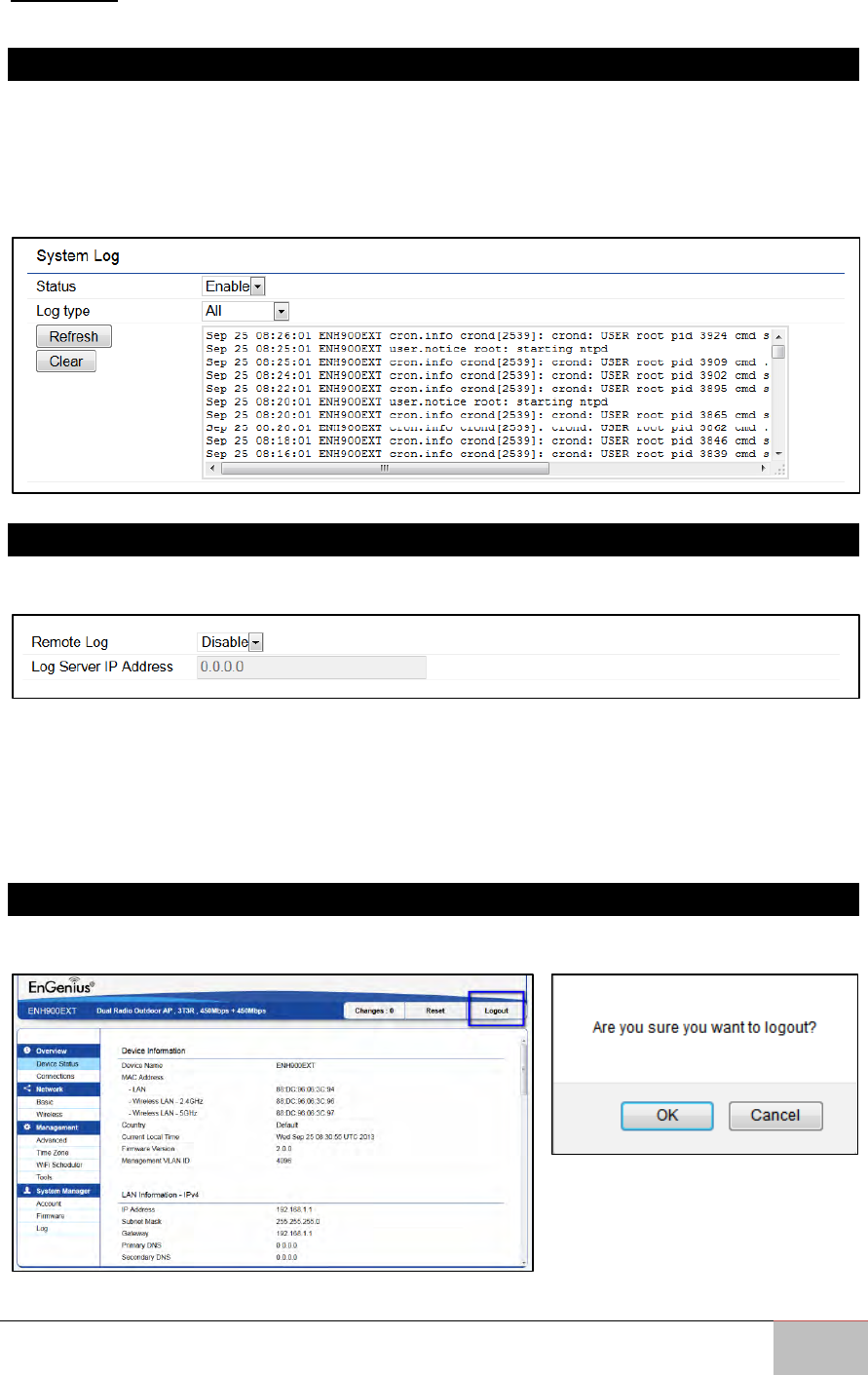
7.10 Log
7.10.1 System Log
The WM-OAP8251AG automatically logs (records) events of possible interest in its
internal memory. To view the logged information, click the Log under the System
Manager menu. If there is not enough internal memory to log all events, older events
are deleted from the log. When powered down or rebooted, the log will be cleared.
7.10.2 Remote Log
This page allows you to setup the Remote Log service for the WM-OAP8251AG.
Syslog: Enables or disables the syslog function.
Log Server IP Address: Enter the IP address of the log server.
Remote Log: Enables or disables the Remote Log service.
Apply: Click Apply to apply the changes.
7.10.3 Logout
Click Logout in the Management menu to logout. Confirm by clicking OK.
User Manual Chapter 7 Management
Outdoor Enterprise Access Point WM-OAP8251AG
65
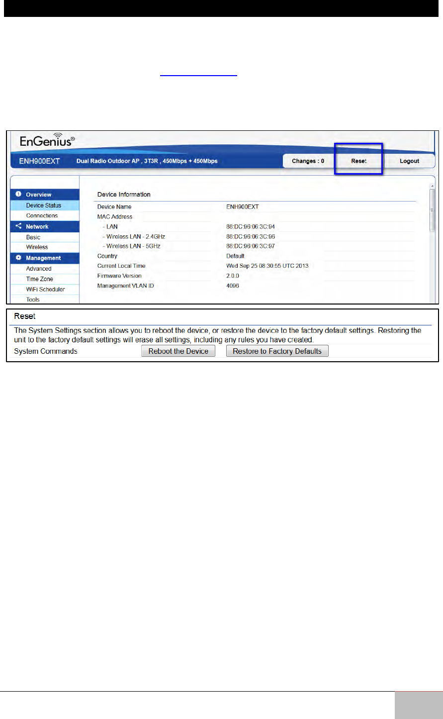
7.10.4 Reset
In some circumstances, it may be required to force the device to reboot. Click on Reset
to reboot the WM-OAP8251AG. Note that this will delete any configurations to their
default settings. Please refer to Backup/Restore section of this User Manual to learn how
to backup and save your customized configuration settings in the event of a Restore.
Click Reboot the Device to confirm a reset or Restore to Factory Defaults to completely
restore the device to its initial factory settings.