Winnix Technologies HYM740 UHF RFID Reader Module User Manual
Winnix Technologies Co., Limited UHF RFID Reader Module
User Manual
UHF RFID Reader Module
HYM740
Winnix Technologies Co.,Limited
RFID Reader Module
- 2 -
Brief introduction
HYM740 UHF RFID reader uses R2000 chip, which complies with EPC C1G2
protocol, its working frequency is 902~928MHz,with LBT function. It supports dense
reader working mode(DRM)。With standard 7dBi antenna,the reading distance can
reach 24 meters, maximum identifying speed can reach 400/S; with simple power
supply and interface circuit, a high-performance RFID system can be established. It is
suitable for logistics, apparel, medical industry, and complex assets management, etc.
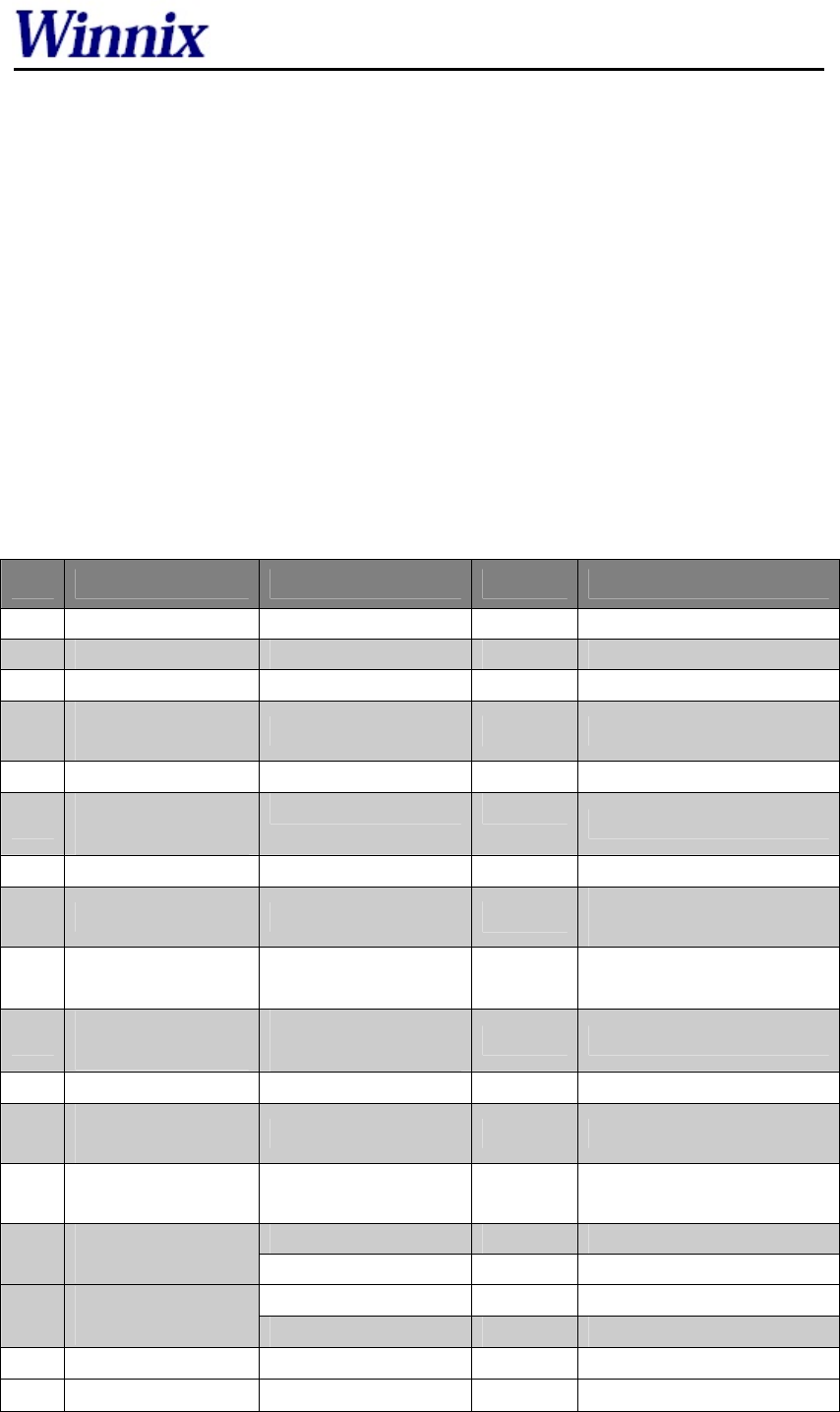
Technical data
No Item Technical data Unit Remark
1 Max current 1.2 A Max power output
2 Standby current ≤1 mA EN pin low level
3 Frequency range 902~928 MHz
4 Default working
frequency Frequency hopping MHz Frequency interval 250KHz
5 Channel bandwidth ≤250 KHz
6 Frequency hopping
speed
≤2 s
7 Fixed power 30 dBm
8 Stepping interval 1~2 dB 5~30dBm, adjustable by
software
9 Label protocol EPC C1G2
/ISO18000-6C
10 Communication
protocol
Asynchronous serial
ports protocol
11 Starting time ≤50 ms
12 Radio-frequency
power rising time ≤500 μs
13 Radio-frequency
power dropping time ≤500 μs
≤-40 dB ±1CH
14 Adjacent channel
power leaking ratio ≤-60 dB ±2CH
±10 ppm -25℃~+40℃
15 Frequency
stabilizing ratio ±20 ppm -40℃~+60℃
16 Max reading range 24 m 7dBi antenna
17 Multi-tags >400/s
RFID Reader Module
- 3 -
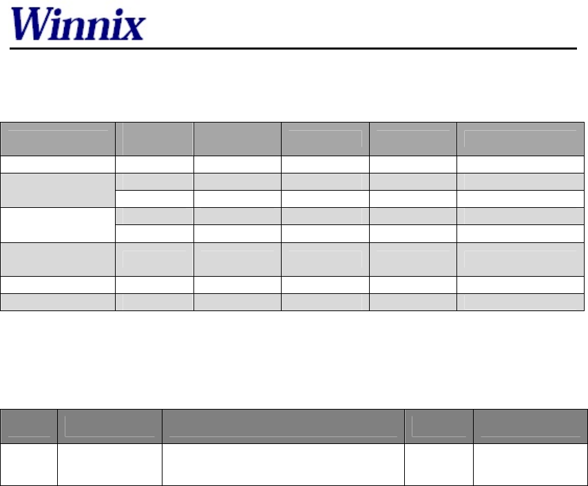
Characteristics of DC
Data Mini
value Typical
value Max value Unit Remark
Voltage of power 4.5 5 5.5 V Direct current
2 3.3 5.5 V GPIO
Input high level 2 - 5 V EN
-0.3 0 0.8 V GPIO
Input low level - - 0.18 V EN
Output high
level 2.9 - - V GPIO
Output low level - 0 0.1 V GPIO
Enable current 2 5 25 uA VEN≥2V
Requirement on antenna
No Item Technical data Unit Remark
1 Standing wave
ratio ≤1.5
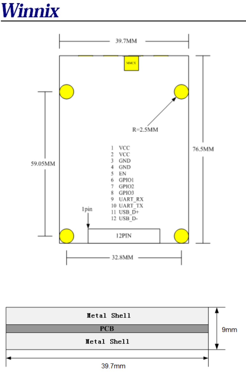
Appearance and structure
z Size: 76.5×39.7×9mm
z Weight: 50g
RFID Reader Module
- 4 -
Drawing 1 Front view of the reader
RFID Reader Module
- 5 -
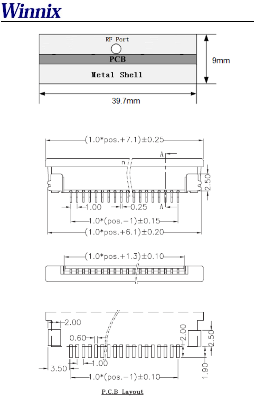
Drawing2 Side view of the reader
Drawing3 Pin connector
RFID Reader Module
- 6 -
Interface definition
Pin Signal name Signal direction Function/compatibility description
1 VCC Input Module supplying power
2 VCC Input Module supplying power
3 GND - Module connecting ground
4 GND - Module connecting ground
5 EN Input Module enabling,highly effective
6 GPIO Bidirection Generic port
7 GPIO Bidirection Generic port
8 GPIO Bidirection Generic port
9 UART_RX Input Asynchronous serial interface receiving
10 UART_TX Output Asynchronous serial interface sending
11 DBG_RX - Test port
12 DBG_TX - Test port
OEMs information: RealID Technology Co., Ltd. was established in December 2012, the
registered capital of 990 million yuan. It is a professional company specializing in RFID system
design, equipment development and related technical services. RealID Technology Co., Ltd.
gathered a number of highly qualified management personnel, first-class product development
elite, to provide customers with first-class hardware products, program design, and custom
services.
Changes or modifications made to the equipment not expressly approved by Winnix may void the
FCC / IC authorization to operate this equipment.
The use of the transceiver module is authorized in mobile or fixed host devices taking into account
the conditions listed below
:• OEM Integrator must ensure that the end user manual may not contain any information about
the way to install or remove the module from the final product.
• Depending on the final host device additional authorization requirements for the nontransmitter
functions of the transmitter module may be required (i.e., Verification, or Declaration of
Conformity) The OEM integrator is responsible for ensuring that a er the module is installed and
operational the host continues to be compliant with the Part 15B unintentional radiator
requirements.
• The information on the label and in the user manual is required to be incorporated in the user
manual of the final host. see 47 CFR15 requirements for more details (e.g. 15.19 / 15.21 / 15.101 /
15.105 / RSSGEN / ICES)
• Additional label with the words ‘Contains FCC ID: RVZHYM740’ shall be applied and visible
from the outside of the host product.

RFID Reader Module
- 7 -
• The module must be installed and used in strict accordance with the manufacturer’s instructions
as described in the user documenta on that comes with the module
.• The end user manual for the final host product operating with this transmitter must include
operatng instructions to satisfy RF exposure compliance requirements. e.g
Radiofrequency radiation exposure Information:
This equipment complies with FCC radiation exposure limits set forth for an uncontrolled
environment. This equipment should be installed and operated with minimum distance of 25 cm
between the radiator and your body.This transmitter must not be colocated or operating in
conjunction with any other antenna or transmitter
.• When the final host product operating with this transmitter deviate from above, installation of
this module into specific final hosts may require the submission of a Class II permissive change
application containing data pertinent to RF Exposure, spurious emissions, ERP/EIRP, and
host/module authen ca on, or new application if appropriate
Feel free to contact us if additional guidance is required.
Manual Requirements according 15.19 / RSSGEN
This device complies with Part 15 of the FCC Rules [and with Industry Canada licence exempt
RSS standard(s)].
Operation is subject to the following two conditions:
(1) this device may not cause harmful interference, and
(2) this device must accept any interference received, including interference that may cause
undesired opera on.
Manual Requirements according 15.21
Changes or modifi ca ons made to this equipment not expressly approved by (manufacturer name)
may void the FCC authorization to operate this equipment.
Environment requirement
No Item Technical data Unit Remark
1 Working
temperature -25~+75 ℃
2 Storage
temperature -40~+85 ℃
3 Relative
humidity 10%~90% RH

RFID Reader Module
- 8 -
Declaration
1) Marketing
The device must be sold to dealers.
2) Professional installation
Installed by licensed professionals ( EUT sold to dealer who hire installers)
3) Application
The intended use is generally not for the general public. It is generally for industry/commercial
use.
RF EXPOSURE
This Module complies with FCC RF radiation exposure limits set forth for an uncontrolled
environment under the following condition: The device shall be used in such way that at least a
distance of 25 centimeters is maintained between the antennas and the body of the user and nearby
persons.
Antenna Information
The HY740 includes an external antenna port.
Here are some design guidelines to help ensure antenna performance:
. Never place the ground plane or route copper traces directly underneath the antenna portion of
the module.
. Never place the antenna close to metallic objects.
. In the overall design, ensure that wiring and other components are not placed near the antenna.
. Do not place the antenna in a metallic or metallized plastic enclosure.
. Do not place the antenna in a metallic or metallized plastic enclosure.
. Keep plastic enclosures 1cm or more from the antenna in any direction.