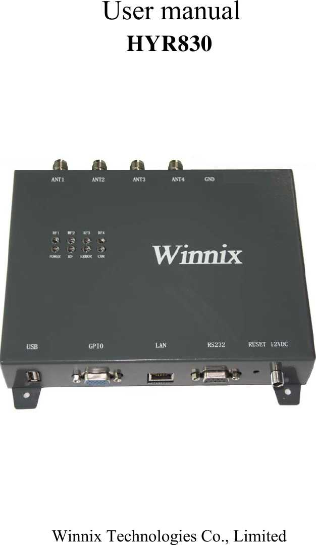
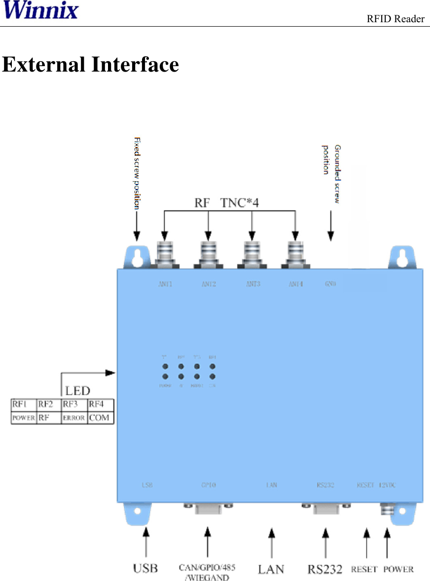
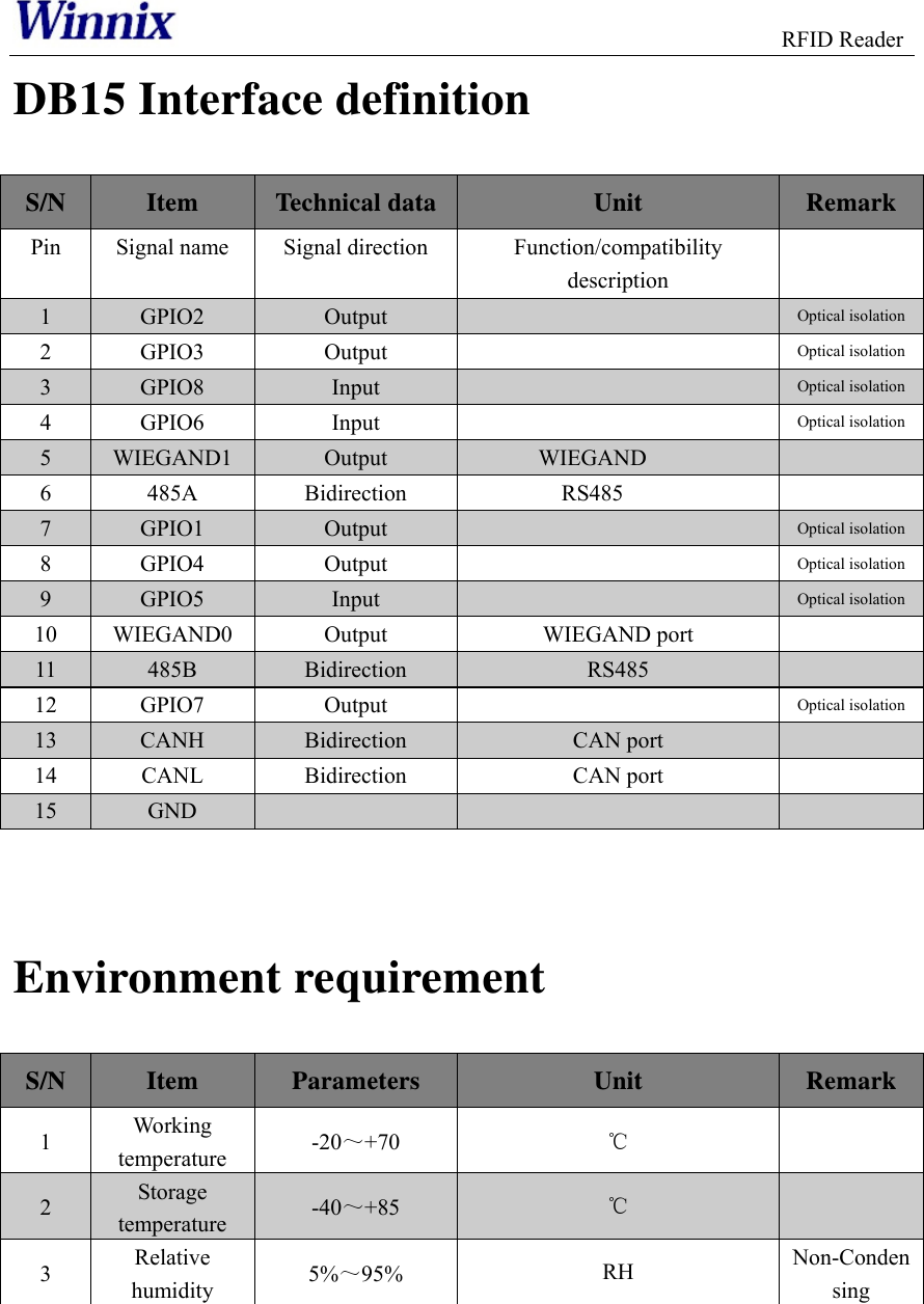
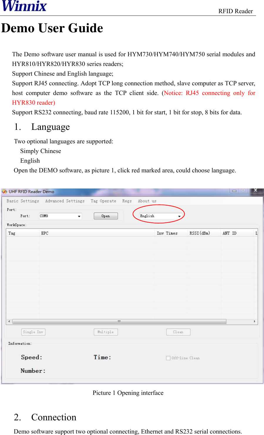
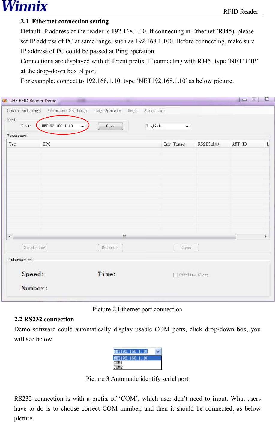
Winnix Technologies HYR830 UHF Reader User Manual HYR830 4Port User manulx
Winnix Technologies Co., Limited UHF Reader HYR830 4Port User manulx
UserManual.wiki
>
Winnix Technologies
>
HYR830 User Manual
Users Manual
Navigation menu
Upload a User Manual
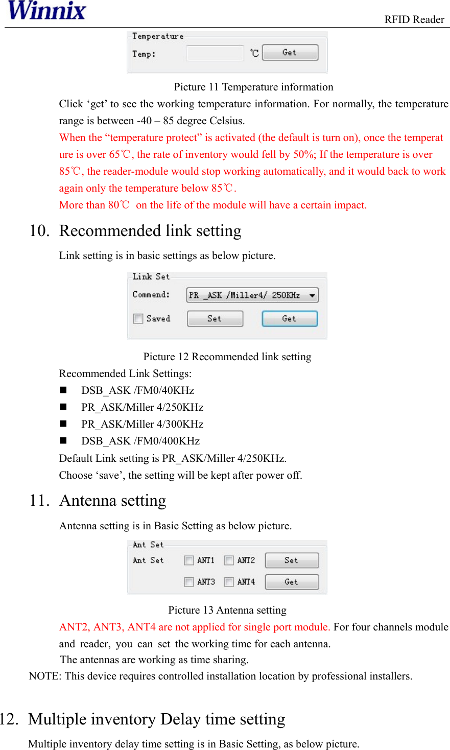
Namespaces
Wiki Guide
HTML
PDF
Info
Views
User Manual
Discussion / Help
Navigation