Winnix Technologies HYR830 UHF Reader User Manual HYR830 4Port User manulx
Winnix Technologies Co., Limited UHF Reader HYR830 4Port User manulx
Users Manual
User manual
HYR830
Winnix Technologies Co., Limited

RFID Reader
Product Introduction
z HYR830 adopts Impinj R2000 module, maximum power output is 30dBm.
z 4 RP TNC ports, with an 7dBi circular polarized antenna, reading distance can
reach 10 meters.
z Reading speed is 400 tags/sec.
z 8 LED lights, real-time display working status.
z Many external ports, Including network interface, RS232、GPIO_IN*4、
GPIO_OUT*4、RS485、wiegand、CAN、USB, can meet different client’s
requirement.
z Excellent read and write performance, it is suitable for complicated environment
application, for example logistics, clothing, asset management etc.
The application of the reader
z Transportation management: road and railway transportation management and
container transportation management and so on.
z motor vehicles management: use it to police station and transport department
supervise and manage the motor vehicles
z Road and bridge charge: as the product is able to read the tag data quickly in
long distance, ,road rate and bridge can be charged without stopping. Vehicles.
z Customs management: the management for goods to pass and transit the customs
and vehicles.
z Logistics and warehouse Management: Goods flow, warehouse management, and
the flowing management of mail, parcel, luggage.
z Parking management: in order to make management and charge automation.
z Doors control management: including vehicles and people to pass in and out
management.
z Craft work manufacture flow: supervise parts in the whole manufacture flow.
The Main Function
z More inventory modes: There are single inventory and multi inventory. Single
inventory for simple application, and multi inventory for complicated
environment, like warehouse management, logistic management.
z Filter function: user can only read or write the tag that they need, like EPC、TID、
USR filter.
z Many management setting: manage the antenna working time, power setting

RFID Reader
z User can read and write the tag, and also kill and lock the tag.
Technical Specifications
S/N Item Parameters Unit Remark
1 Operating voltage 12 V
2 Maximum Current 800 mA
3 Standby current ≤100 mA
4 Frequency range 840-960 MHz Standard:902-928MHz,custo
mized optional
5 Default operating
frequency
Frequency
hopping MHz Frequency interval 250KHz
6 Channel bandwidth 250 KHz
7 Frequency hopping
speed
≤2 s
8 Maximum power
output 30 dBm
9 Step interval 1 dB 5~30dBm adjustable by
software
10 Label protocol EPC C1G2
/ISO18000-6C
11
Radio-frequen
cy power
rising time
≤500 μs
12 Radio-frequency
power dropping time ≤500 μs
13
Adjacent
channel power
leaking ratio
≤-40 dB ±1CH
≤-60 dB ±2CH
14 Frequency
stabilizing ratio
±10 ppm -25℃~+40℃
±20 ppm -40℃~+60℃
15 Maximum reading
range
10 m 7dBi Antenna
16 Multi-Label >400/s
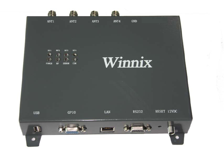
Appearance and structure
z Size(L*W*H):190×145×30mm
z Weight:300g
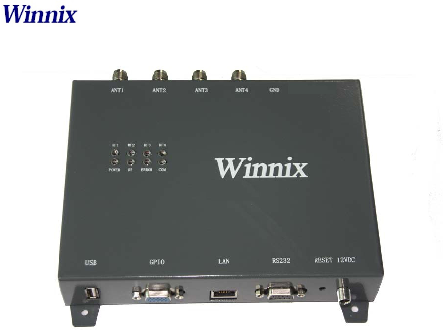
RFID Reader
Picture1 Front view
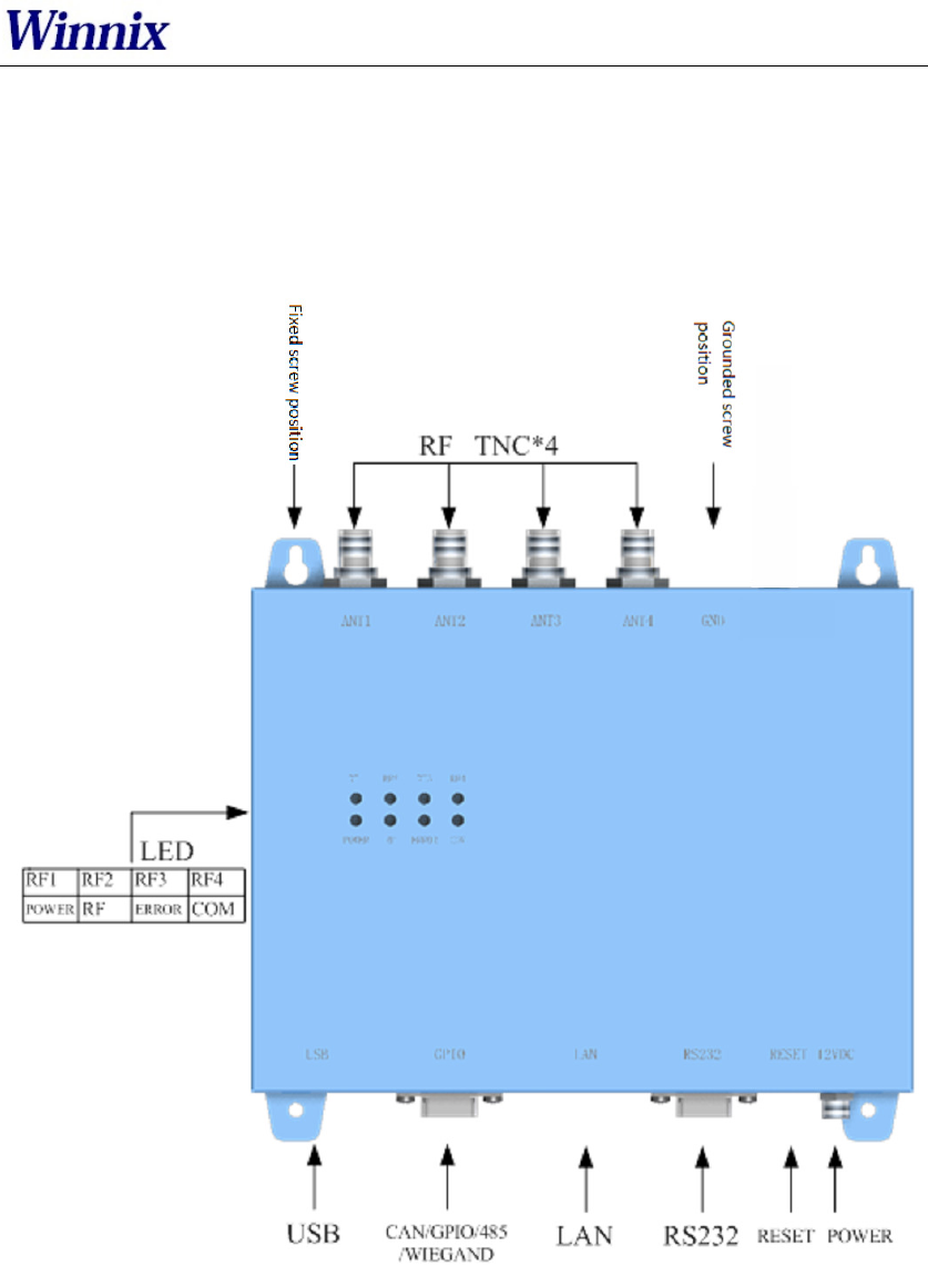
RFID Reader
External Interface

RFID Reader
DB15 Interface definition
S/N Item Technical data Unit Remark
Pin Signal name Signal direction Function/compatibility
description
1 GPIO2 Output Optical isolation
2 GPIO3 Output Optical isolation
3 GPIO8 Input Optical isolation
4 GPIO6 Input Optical isolation
5 WIEGAND1 Output WIEGAND
6 485A Bidirection RS485
7 GPIO1 Output Optical isolation
8 GPIO4 Output Optical isolation
9 GPIO5 Input Optical isolation
10 WIEGAND0 Output WIEGAND port
11 485B Bidirection RS485
12 GPIO7 Output Optical isolation
13 CANH Bidirection CAN port
14 CANL Bidirection CAN port
15 GND
Environment requirement
S/N Item Parameters Unit Remark
1 Working
temperature -20~+70 ℃
2 Storage
temperature -40~+85 ℃
3 Relative
humidity 5%~95% RH Non-Conden
sing
RFID Reader
Demo User Guide
The Demo software user manual is used for HYM730/HYM740/HYM750 serial modules and
HYR810/HYR820/HYR830 series readers;
Support Chinese and English language;
Support RJ45 connecting. Adopt TCP long connection method, slave computer as TCP server,
host computer demo software as the TCP client side. (Notice: RJ45 connecting only for
HYR830 reader)
Support RS232 connecting, baud rate 115200, 1 bit for start, 1 bit for stop, 8 bits for data.
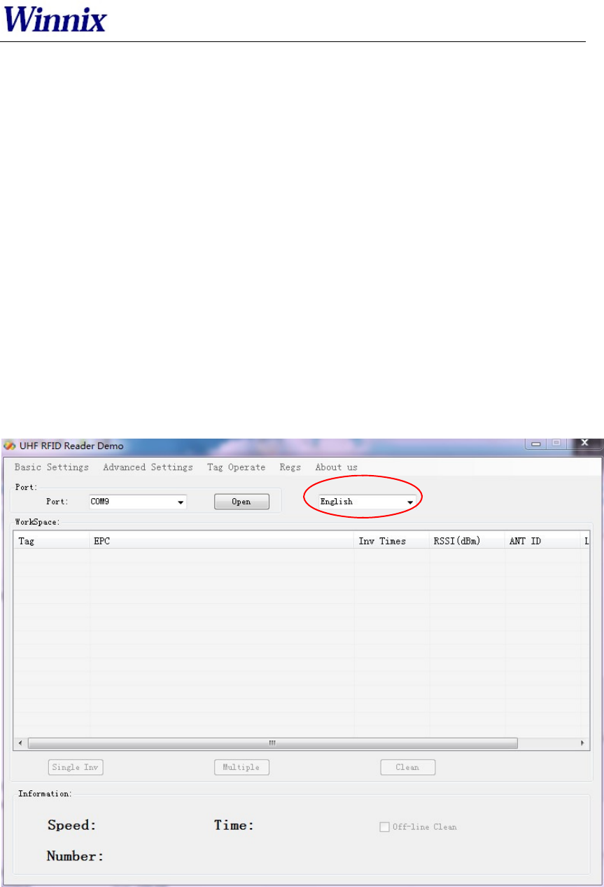
1. Language
Two optional languages are supported:
Simply Chinese
English
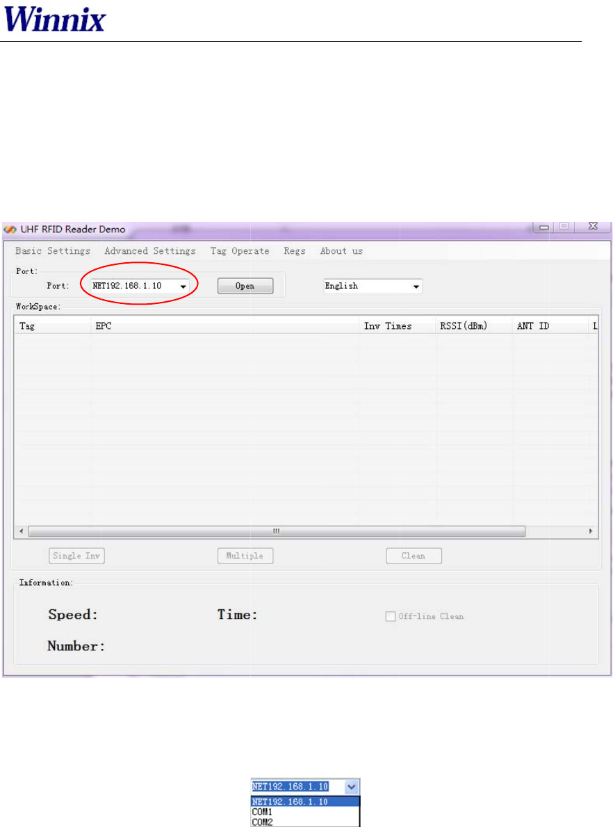
Open the DEMO software, as picture 1, click red marked area, could choose language.
Picture 1 Opening interface
2. Connection
Demo software support two optional connecting, Ethernet and RS232 serial connections.
2.1 Ethe
r
Default I
P
set IP ad
d
IP addres
s
Connecti
o
at the dro
p
For exa
m
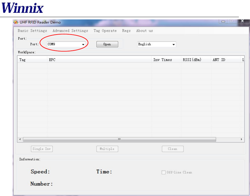
2.2 RS232
c
Demo soft
w
will see bel
o
RS232 con
n
have to do
picture.
r
net connec
t
P
address of
t
d
ress of PC a
t
s
of PC coul
d
o
ns are displ
a
p
-down box
o
m
ple, connect
t
c
onnection
w
are could a
u
o
w.
n
ection is wi
is to choose
t
ion setting
t
he reader is
1
t
same range,
d
be passed a
t
a
yed with dif
f
o
f port.
t
o 192.168.1
.
Picture
2
u
tomatically
Picture 3
A
th a prefix
o
correct CO
M
1
92.168.1.10
such as 192.
t
Ping operat
i
ff
erent prefix.
.
10, type ‘N
E
2 Ethernet p
o
display usa
b
A
utomatic id
e
o
f ‘COM’,
w
M
number,
a
.
If connecti
n
168.1.100.
B
i
on.
If connectin
g
E
T192.168.1.
o
rt connectio
n
b
le COM po
r
e
ntify serial
p
w
hich user d
o
a
nd then it s
h
n
g in Etherne
t
efore conne
c
g
with RJ45,
1
0’ as below
n
r
ts, click dro
p
ort
o
n’t need to
i
h
ould be co
n
RFID Re
t
(RJ45), ple
a
c
ting, make s
u
type ‘NET’
+
picture.
o
p-down
b
ox
,
i
nput. What
n
nected, as
b
ade
r
a
se
u
re
+
’IP’
,
you
users
b
elow
RFID Reader
Picture 4 RS232 port connection
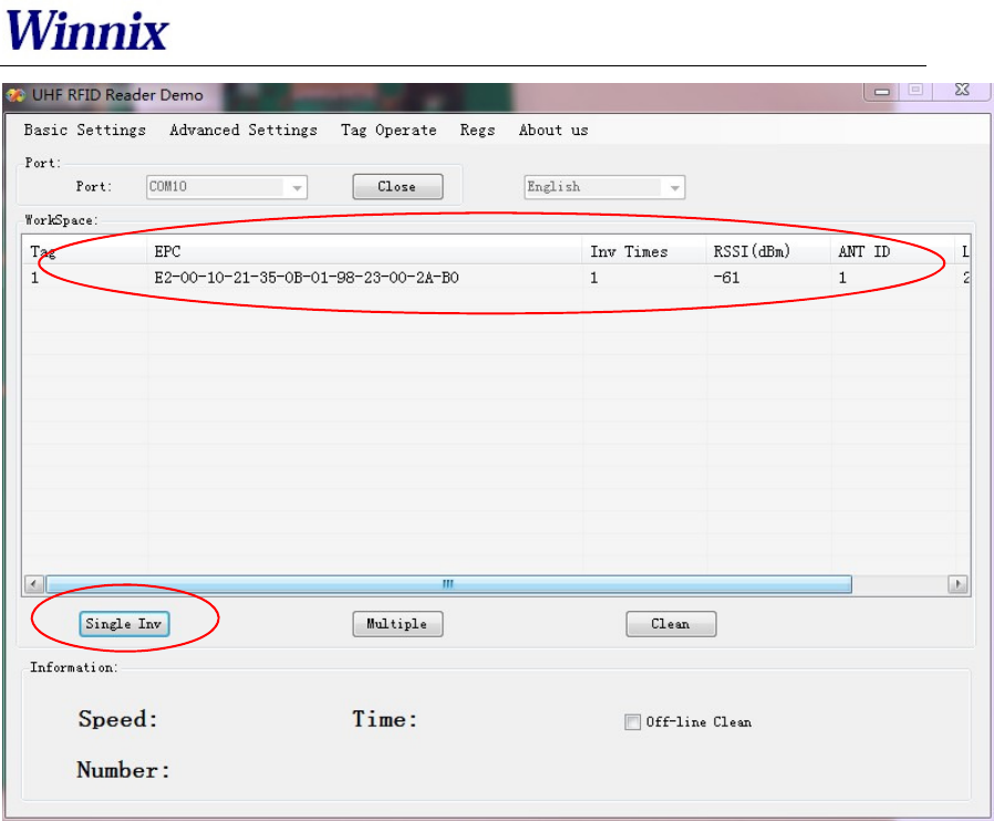
3. Single inventory operation
Single inventory operation is in ‘singe ask’ and ‘single answer’ method of reading. Each
inventory will result an acknowledgement frame. In each single inventory, only one tag’s
EPC data could be gotten.
Single inventory mode supports to inventory tag function at any length EPC code. At
workspace area, it could display EPC code, Inventory times, RSSI for each tag, as below
picture.
RFID Reader
Picture 5 Single inventory mode
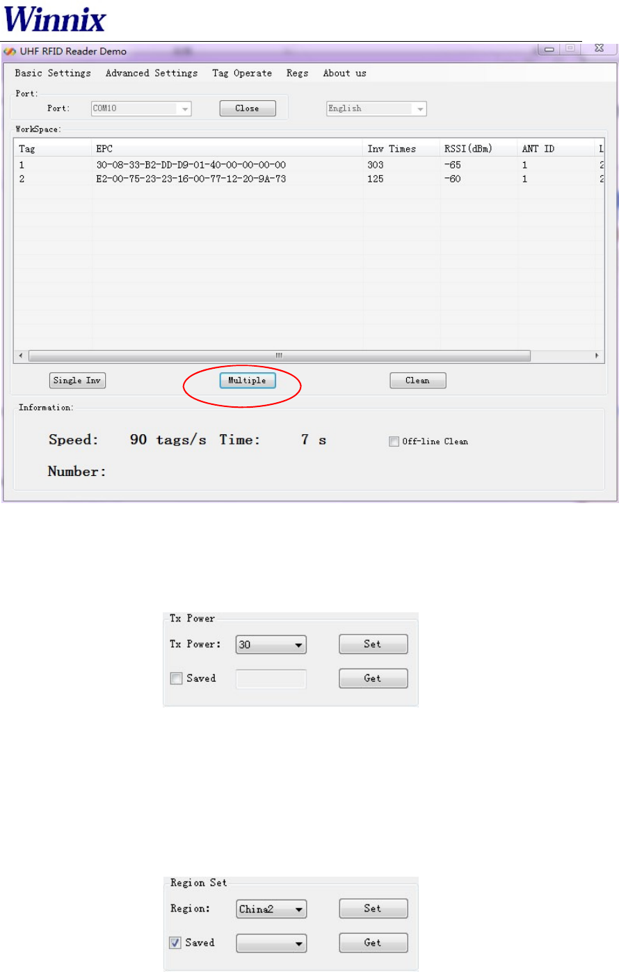
4. Multiple inventory operation
Below picture is for multiple inventory mode. Inventory times are non-limited. At
information area, it will display Inventory speed, time and tag numbers. Click ‘off-line clean’,
it will launch the function. If a tag is not read in 4 seconds, the marked color of the tag will
turn grey, if over 8 seconds, the tag will be cleared from workspace.
RFID Reader
Picture6Multipleinventorymode
5. RF output power setting
TX power setting is in basic settings section, below picture is for TX power setting.
Picture 7 RF output power setting
The TX power range is 5-30dBm, with 1dBm stepping up. ‘Set’ the picked power, and
then ‘get’ for checking the result.
Choose "save", the setting will be kept after power off.
6. Region setting
Region setting is in basic settings section, as below picture.
Picture 8 Region setting
RFID Reader
Region setting includes
China1 area (840.625MHz~844.375MHz),
China2 area (920.625MHz~924.375MHz),
Europe area (865.7MHz~867.5 MHz),
USA area (902MHz~928MHz),
Korea and Japan area.
Choose the frequency band at your area, and then click ‘set’, ‘get’ is to check the
current band you have chosen.
Choose "save", the setting will be kept after power off.
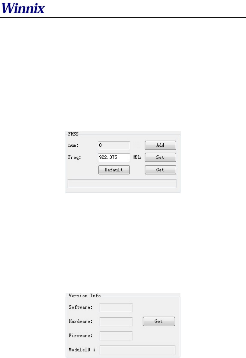
7. Frequency hopping setting
Frequency hopping setting is in basic settings as below picture.
Picture 9 Frequency hopping setting
Click ‘get’, you will see the each hopping points of the frequencies.
Fixed frequency setting: fill in the frequency at the blank then click ‘add’, then click
‘set’, if successful, it will notice. Click ‘get’ can check out the set value.
Self-defining frequency hopping setting: input one frequency point, click ‘add’; then
input another, click ’add’. Repeat till you add all frequency points, then click ‘set’.
You can click ‘get’ to check if setting successfully.
8. Version info
Version information is displayed in basic settings as below picture.
Picture 10 Version information
Click ‘get’, you will get the version information, including Software version,
Hardware version, Firmware version and Module ID.
9. Temperature info
Temperature info is displayed in basic settings as below picture.
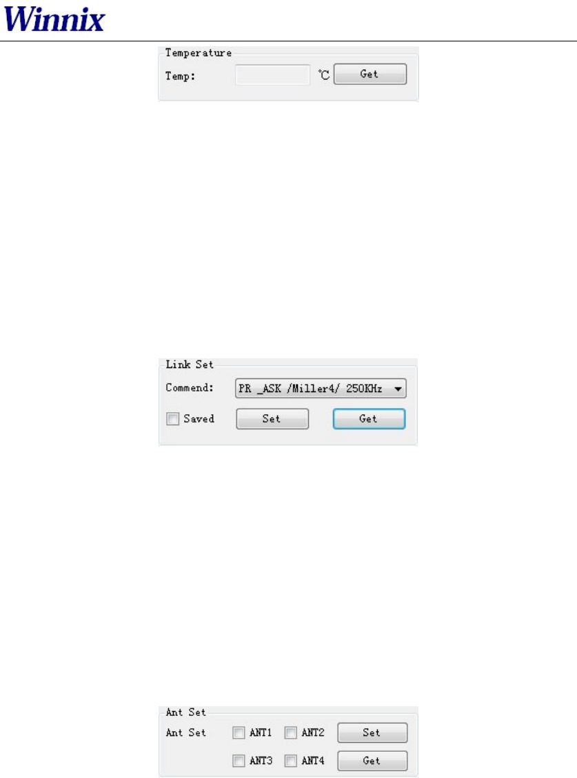
RFID Reader
Picture 11 Temperature information
Click ‘get’ to see the working temperature information. For normally, the temperature
range is between -40 – 85 degree Celsius.
When the “temperature protect” is activated (the default is turn on), once the temperat
ure is over 65 ,℃ the rate of inventory would fell by 50%; If the temperature is over
85 ,℃ the reader-module would stop working automatically, and it would back to work
again only the temperature below 85 . ℃
More than 80℃ on the life of the module will have a certain impact.
10. Recommended link setting
Link setting is in basic settings as below picture.
Picture 12 Recommended link setting
Recommended Link Settings:
DSB_ASK /FM0/40KHz
PR_ASK/Miller 4/250KHz
PR_ASK/Miller 4/300KHz
DSB_ASK /FM0/400KHz
Default Link setting is PR_ASK/Miller 4/250KHz.
Choose ‘save’, the setting will be kept after power off.
11. Antenna setting
Antenna setting is in Basic Setting as below picture.
Picture 13 Antenna setting
ANT2, ANT3, ANT4 are not applied for single port module. For four channels module
and reader, you can set the
working time for each antenna.
The antennas are working as time sharing.
NOTE: This device requires controlled installation location by professional installers.
12. Multiple inventory Delay time setting
Multiple inventory delay time setting is in Basic Setting, as below picture.
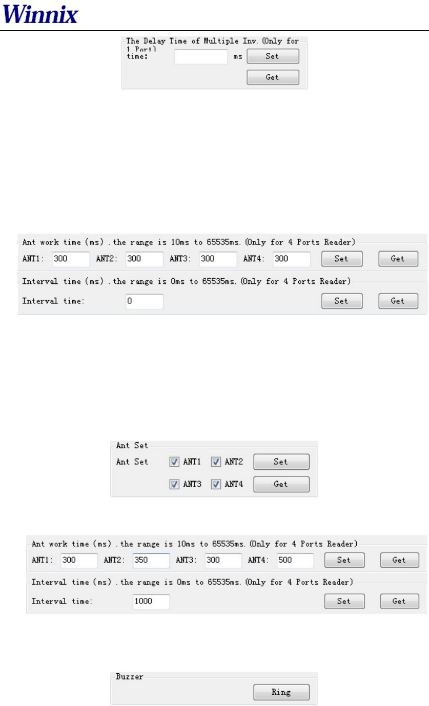
RFID Reader
Picture 14 Multiple inventory Delay time setting
The setting is for module waiting time after one inventory cycle during the multiple
inventory working. This is only applied for single port module. Default value is 0
during multiple inventory. At such case, the module will be working at full load, while
the module temperature will be higher.
13. Antenna working and interval time setting
Antenna working and interval time setting is in Basic Setting, as below picture.
Picture 15 Antenna working and interval time setting
The setting is for each antenna working time and interval time during multiple
inventory. Before the setting, you should choose the antenna number.
For instance, if want to set ANT1 of working time 300ms, ANT2 of working time
350ms, ANT3 of working time 300ms, ANT4 of working time 500ms, and waiting
1000ms for once reading cycle, see following steps:
a) Click ANT1, ANT2, ANT3, ANT4, and ‘set’;
b) Set ANT1 of working time 300ms, ANT2 of working time 350ms, ANT3 of
working time 300ms, ANT4 of working time 500ms, and interval time is 1000ms.
14. Buzzer setting
Buzzer setting is in Basic Setting as below picture.
Picture 16 Buzzer setting
Notice: The function is only for HYR830 reader.
RFID Reader
Click ‘Ring’, you will hear the alarm from the reader.
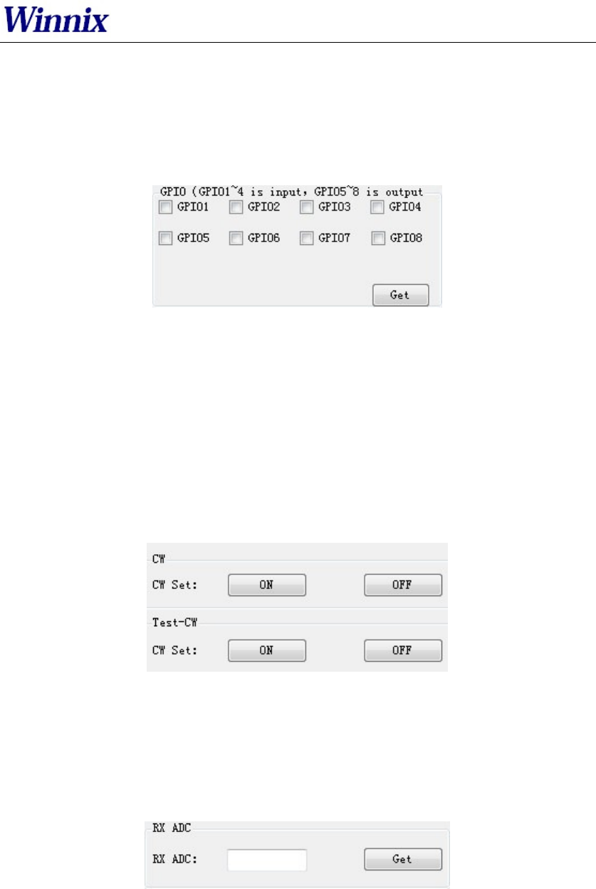
15. GPIO setting
GPIO setting is in Basic Setting as below picture.
Picture 17 GPIO setting
Notice: HYM series modules only have 3 output IO ports (GPIO1, GPIO2 and GPIO3).
HYM830 reader has 4 output IO ports (GPIO1, GPIO2, GPIO3, GPIO4), and 4 input
IO ports (GPIO5, GPIO6, GPIO7, GPIO8)
The picked output IO ports will output high level, otherwise will output low level. If
connecting input IO ports at high level, click ‘get’, you will see the picked IO ports;
while at low level, the IO ports are not picked.
16. CW setting
CW setting is in advanced settings as below picture.
Picture 18 CW setting
Click ‘ON’ to open single carrier wave transmit, ‘OFF’ is to close single carrier wave
transmit. ‘Test-CW’ is for testing, please ignore it.
17. RX ADC info
RX ADC information is displayed in advanced settings as below picture.
Picture 19 RX ADC information
RX ADC is very important for checking the matching and connection of the antenna
with module or reader. If the data is above 10, there may be connection problem or
no-matching. At the time, please re-check the connection of antenna, or remove it, otherwise it
will damage the module or reader. If the data is below 10, the antenna can be worked.
RFID Reader
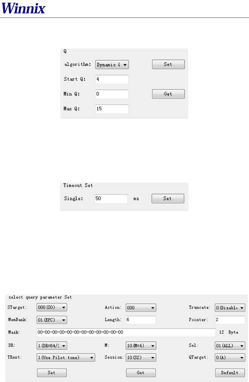
18. Q setting
In Advanced Settings, below is the picture of Q setting.
Picture 20 Q setting
There are two ways of dynamic Q and static Q. Dynamic Q is recommended, as it
could automatically adjust the Q value to achieve most fast inventory.
19. Single inventory timeout setting
In Advanced Settings section, below is the picture for single inventory timeout setting
Picture 21 Single inventory timeout setting
This function is only for single inventory. If single read is unsuccessful, after the
overtime, the reader will report the result. If the reading is successful during the
overtime, the response will be appeared immediately.
20. Select and Query Setting
In Advanced Settings section, below is the picture for Select and Query parameter
setting
Picture 22 Select and Query setting
Please read detail instruction for Select and Query command in ISO18000-6C
protocol.
21. Tag reading and writing setting
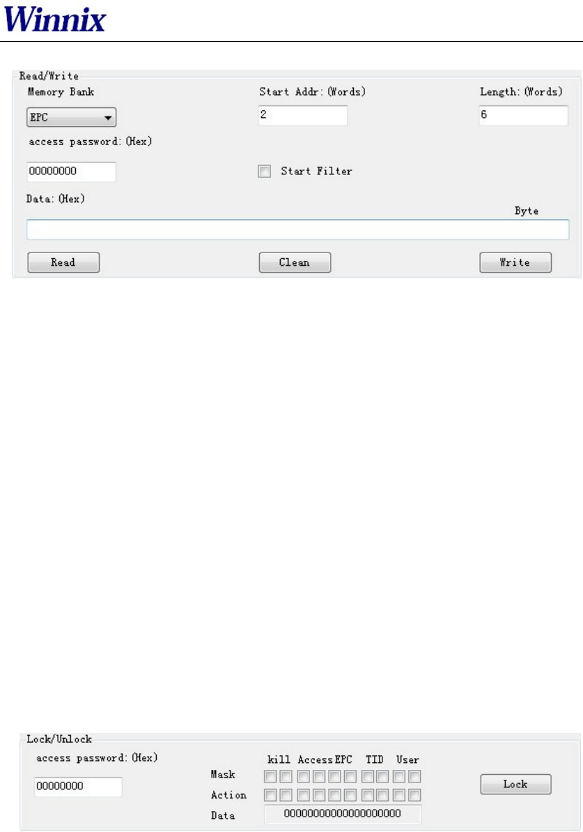
RFID Reader
In Tag Operate section, below is the picture for tag reading/writing setting
Picture 23 Tag reading and writing setting
Memory Bank is data area of the tag, which includes RFU, EPC, TID and USR.RFU is
for password zone of the tag, including Access Password (AccPwd) and Kill Password
(Killpwd). EPC is the ID number of the tag, usually at 12 bytes. TID is the worldwide
sole ID code, and includes the information of tag IC company. USR is data zone for
users, for some kind of tag there is no the USR data zone.
Start address is for the beginning address of data reading and writing. Unit is word
(One work equals to 2 bytes).
Length is to show the length of data write. Unit is word (One work equals to 2 bytes).
Access password: this is only for the reading and writing on those locked tag. Notice
that you can read EPC information of the tag even the tag has been locked, but have to
access the password for writing. TID is only for read, can’t for write.
Read/Write setting is usually operated with filter operation, which means you can
read/write those picked EPC tag, and avoid to reading/writing un-picked tags. Steps
are as following:
Find the tag on ‘workspace’ which you want to reading and writing, double-click the
EPC number, enter ‘tag operate’ interface, then you can operate.
22. Tag Lock setting
In Tag Operate section, below is the picture for Tag Lock setting.
Picture 24 Tag lock setting
At RFU zone, KillPwd and AccPwd could set separately.
There are four kinds of operation for lock setting in each zone, including Unlock,
Normal lock, Permanent lock, Permanent Unlock, and usually for Lock and normal
lock operations.
Tag lock setting is usually operated with filter operation, which means you can lock
those picked EPC tags, and avoid locking un-picked tags. Steps are as following:
Find the tag on ‘Workspace’ which you want to lock, double-click the EPC number,
RFID Reader
enter ‘tag operate’ interface, then you can operate.
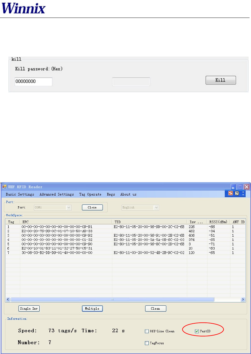
23. Tag Kill setting
In Tag Operate section, below is the picture for Tag Kill setting.
Picture 25 Tag kill setting
It is supported by ISO18000-6C protocol the reader could kill the tags permanently. Please caution
the killed tag could not be usable.
Tag Kill setting is usually operated with filter operation, which means you can kill the picked EPC
tags, and avoid killing un-picked tags. Steps are as following:
Find the tag on ‘Workspace’ which you want to kill, double-click the EPC number, enter ‘tag
operate’ interface, then you can operate.
24. FastID Function
Picture26 FastID Operation screen
ClickFastIDthen you can start FastID function
When you open FastID,on single inventory and continuous inventory, the EPC and TID
of the tag will be shown together.
Attention, only if the tag support FastID function, then you can use this function, if the tag
didn’t support this function, you only can get EPC.
RFID Reader
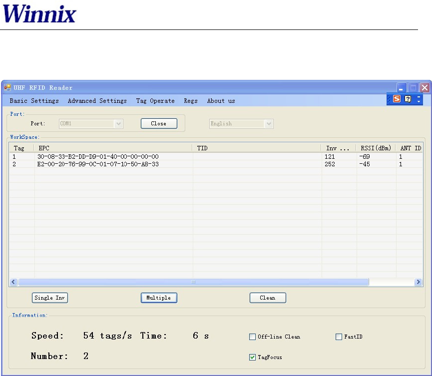
25. TagFocus Function
Picture27 TagFocus Operation screen
ClickTagFocus,then you can start TagFocus function

FCC Caution
Any Changes or modifications not expressly approved by the party responsible for
compliance could void the user’s authority to operate the equipment.
This device complies with part 15 of the FCC Rules. Operation is subject to the
following two conditions: (1) This device may not cause harmful interference, and
(2) this device must accept any interference received, including interference that
may cause undesired operation.
Note: This equipment has been tested and found to comply with the limits for a
Class B digital device, pursuant to part 15 of the FCC Rules. These limits are
designed to provide reasonable protection against harmful interference in a
residential installation. This equipment generates uses and can radiate radio
frequency energy and, if not installed and used in accordance with the instructions,
may cause harmful interference to radio communications. However, there is no
guarantee that interference will not occur in a particular installation. If this equipment
does cause harmful interference to radio or television reception, which can be
determined by turning the equipment off and on, the user is encouraged to try to
correct the interference by one or more of the following measures:
—Reorient or relocate the receiving antenna.
—Increase the separation between the equipment and receiver.
—Connect the equipment into an outlet on a circuit different from that to which the
receiver is connected.
—Consult the dealer or an experienced radio/TV technician for help.
www.winnix.net
FCC Radiation Exposure Statement:
This equipment complies with FCC radiation exposure limits set forth for an
uncontrolled environment .This equipment should be installed and operated with
minimum distance 25cm between the radiator& your body.
This transmitter must not be co-located or operating in conjunction with any other
antenna or transmitter.
16