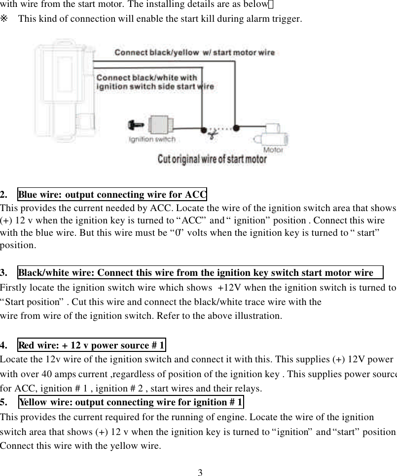
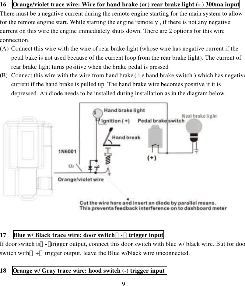
Wintecronics TR68B Remote Control Car Alarm Transceiver User Manual
Wintecronics Ltd Remote Control Car Alarm Transceiver Users Manual
UserManual.wiki
>
Wintecronics
>
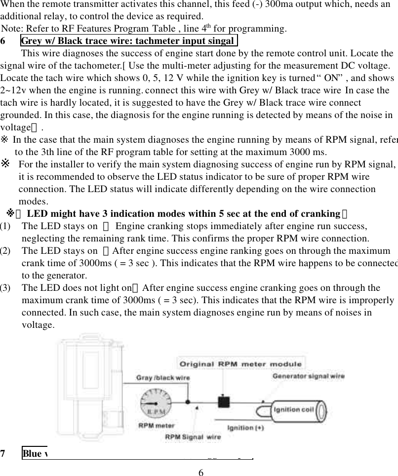
TR68B User Manual
User Manual
Navigation menu
Upload a User Manual
Namespaces
Wiki Guide
HTML
PDF
Info
Views
User Manual
Discussion / Help
Navigation
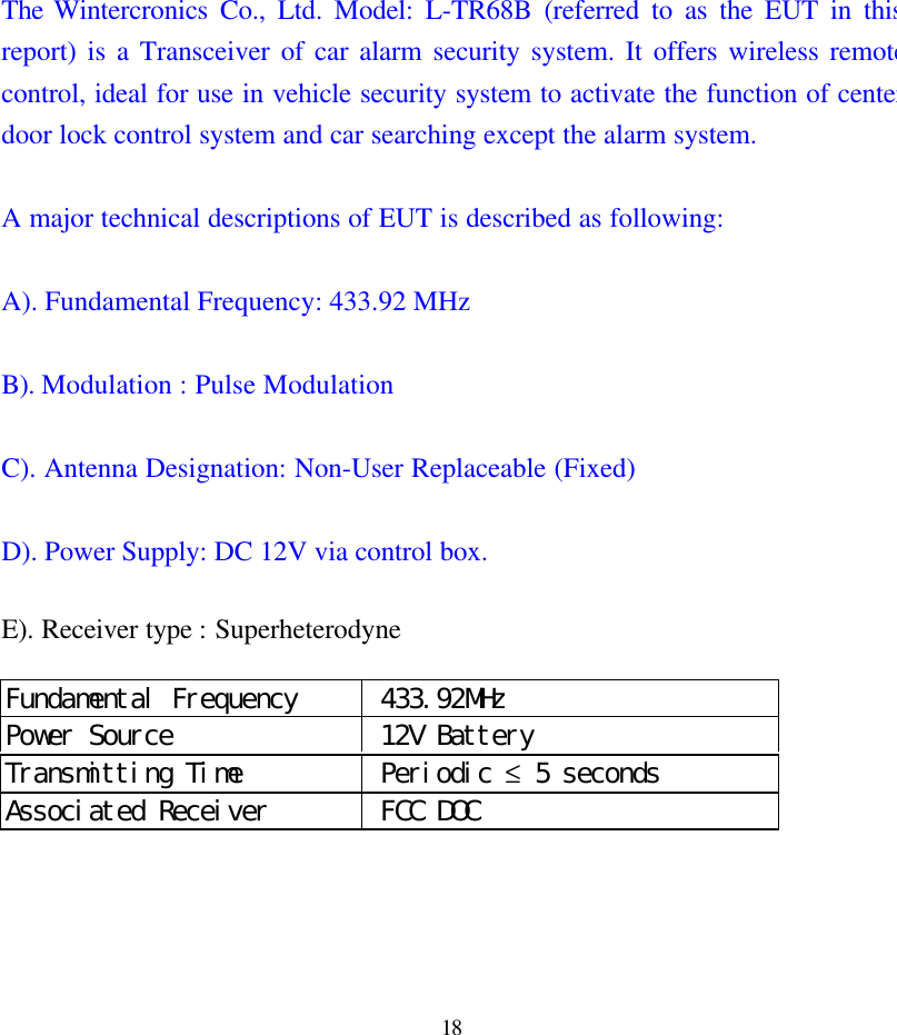
![1Model No. : L-TR68B1. The L-TR68B is a 2-way security system featured with remote engine start and can beinstalled to work with any vehicle with its normal voltage of 12 volt.2. The L-TR68B’s circuit is designed to suit both the manual gear and the auto-transmissiongear car for remote engine starting.3. The L-TR68B has 2 different engine start time circuit for remote starting of both gasolineengine and diesel engine.Installation of the major components Choice of place for main control moduleInstall this behind the dashboard at the suitable position, near the ignition cylinder (within 60 cmfrom it) but far from the heat source and water tank.l SirenChoose its location in the engine compartment [far from the heat source and water tank, and freefrom theengine’s moving parts]. Drill a hole of 1/8 in drill at the selected place and secure the siren usingthe mounting bracket, facing the siren downward or in the horizontal position.l Hood switchWhile in arm mode or remote engine running, this helps the main control module detect thehood’s status .It must be installed on the grounded metal surface. Drill a hole of 1/4 inch at theselected place and secure the hood switch and adjust it. [The switch must have negative outputwhen the hood is opened, and becomes neutral when the hood is closed.] Dash LED Status indicatorDuring the security standby mode, this performs as a visual indicator against attempted theft andalso is the current status indicator of the system. During programming of system features, theLED’s flashing pattern provides feedback as a confirmation for different active modes beingachieved. Mount the LED at a suitable area to ensure better visibility either from inside oroutside of the vehicle. Override switchSystem’s programming can be done using override switch as in the manual entry into valet mode,manual arm/disarm. It may not require concealment because the main system itself has othermulti-security features. Then connect it with the system’s modules for valet switch.](https://usermanual.wiki/Wintecronics/TR68B/User-Guide-244727-Page-1.png)
![2 RF transmitter module/ call buttonThis is integral part of the main system for transmitting / receiving and paging by push button.Select its mounting place to insure the best transmission range. It is suggested to fix it on the leftor right upper area of the interior side of the windshield, using the double stick tape included. Besure not to block driver’s view. Anti –carjack switchWhile ignition “ON”, entry and exit of anti-carjack mode can be done by this switch. Select themounting place within reach of the driver but must be a concealed place Drill a 5/32 inch holefor mounting it. Connect one end of its wire to the system’s negative and the other to the anti-carjack wire from the main system.[This wire gets negative input to make the main system to enter anti-carjack mode] Shock sensorWhile in arm mode, this helps the main system detects impacts upon the vehicle. It must be fixedonto the chassis or stable metal surface.[ keeping far from heat source , water tank and vehicle’stransmitter module ] .Adjust it for the optimal sensitivity. While in arm mod twist the adjustmentpole to the (+) direction to make it more sensitive and to the (-) direction for lesser sensitivity.[Strike with your palms or shake the vehicle’s body and observe if the LED turns on in greencolor during light impact and it turns on in red color during heavy impact.]※ Wire installation guideThis is the 2-way security system with remote engine start features. While the system is action,L-TR68B’s circuit interaction during remote controlling is the same situation with an ignitionkey. As the starter circuit differs depending on the car manufacturers, the main system’s circuitmust be verified before wiring.THE 6 PIN MAIN POWER HARNESS WIRE:1. Black/yellow trace wire: Connect this to the wire from the start motor wire Firstly locate the ignition switch wire which shows +12V when the ignition switch is turned to“Start position” . Cut this wire as in below illustration. Then connect the black/yellow trace wire](https://usermanual.wiki/Wintecronics/TR68B/User-Guide-244727-Page-2.png)
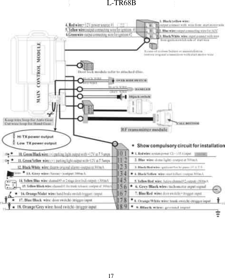
![46. Green wire: output connecting wire for ignition # 2Locate the wire of the ignition switch area that shows (+) 12 v when the ignition key is turned to“ ignition” and “start” . Connect this wire with the green wire.Note:In some vehicles, this wire shows “0” volts while the engine is starting or cranking. But insome vehicles, this provides +12 v current. Program this as required. [ Refer to RFFeatures Program Table 1, line 7th ] 。l THE 18 PIN INPUT/OUTPUT HARNESS WIRE1. Red wire: system power 12 V (+) 15 A inputThis wire supplies power to the system main module locate the 12v wire of the ignition switchand connect it with this. This supplies (+) 12V power with over 15 amps current connect thiswire to the positive .2 Blue wire: dome light (-) output at 300maDome light trigger: While the main system from arm to disarm or “alarm run away” modes, thiswire provides (-) 300mA current to turn the dome light on through the external relay. Installationdiffers depending on the types of vehicles.A TYPE: This installation of this wire is not needed for vehicle with a dome light controlled bydoor lock/unlock action.B TYPE: An additional relay is required for vehicle with original dome light whose device iscontrolled by driver door switch trigger. The installing details are as below. [Refer tofeature program table, item 14 with setting at 0.8 sec]](https://usermanual.wiki/Wintecronics/TR68B/User-Guide-244727-Page-4.png)
![5C TYPE: For the vehicle with no dome light, an additional relay is required. The installingdetails are as below.[Refer to RF Feature Program Table, line 14th for setting at 6sec]3 Black w/ Red trace wire: ignition # 3 or bypass V.A.T.S. (-)output at 300maWhile the system is in remote engine start mode; this feeds (-) 300ma current. Some vehiclesneed this circuit for the engine running .If there is no such device, an additional relay is requiredfor the control of light.4 Black w/ Yellow trace wire: start killer (-) output 300maWhen the main system is armed and remote start engine running time this feeds (-)pulse of300ma which. If this circuit will be used to kill ignition or disrupt the gas pump, a 3 pinblack/red and 2 external relays are required .Refer to the following installation guide. 5 Yellow w/ Red trace wire: Active channel # 2 ,output (-) 300ma](https://usermanual.wiki/Wintecronics/TR68B/User-Guide-244727-Page-5.png)
![7If the door switch is(+)trigger, connect this with the Blue w/ Red trace wire. If the door is(-)trigger, leave the Blue w/ Red trace wire unconnected.8 Orange w/ White trace wire: trunk switch (-) trigger inputIf the trunk switch is (-)trigger, connect trunk switch pin with the orange w/ white trace wire.9 Black wire : ground(-)This wire supplies current for the main module and needs to be grounded on a stable metalsurface in the installation.※ Improper wiring can cause problem and even disable engine start.10 Green w/ Black trace wire: (+) parking light output with +12 v at 7.5 AWhile the system is in action, the main system feeds, through onboard relay, different times of (+)12 v current for lamp signal. Locate the left or right parking light wire from the directionindicator switch and connect it.※ Both wires of left and right parking light from direction indicator switch must have positiveoutput.11 Green w/ Yellow trace wire: (+) parking light output with +12 v at 7.5 AWhile the system is in action, the main system feeds, through onboard relay, different times of (+)12 v current for lamp signal. Locate the left or right parking light wire from the directionindicator switch and connect it.※ Both wires of left and right parking light from direction indicator switch must have positiveoutput.12 Black w/ White trace wire: disarm original alarm (-) output at 300maWhen the main system enters remote engine start mode, this circuit provides –300ma current for1.5 sec. [ For vehicle with chip-controlled anti-theft system, this circuit needs installation ofadditional accessory or relay to by-pass such immobilization]. This does not need installation onthe car without anti-theft chip.13 Grey wire: Siren(+)output 1.5 AFor different action by main system; the main system feeds different (+) 12v for alert signal.](https://usermanual.wiki/Wintecronics/TR68B/User-Guide-244727-Page-7.png)
![8Connect this wire with the red wire of the siren or use an additional relay to connect with theoriginal horn.※ (Refer to RF Features Program Table , line 6th )14 Yellow w/ Blue trace wire: for Active channel #3 or 2 stage door lock output (-) 300maOne of the options can be chosen as required. (a) active channel # 3 and (b) 2 stage door unlock[ for 1st stage to open the driver’s door and for 2nd stage to open all other doors].(A) active channel # 3:If this option is chosen, when the remote transmitter activates this channel, it feeds (-) 300mapulse current whose pulse time can be programmed. An additional accessory is required for thecontrol of other device.Note: Refer RF Features Program Table, line 10th & 5th for pulse time programming.(B) 2 stage door unlock:If this option is chosen, when the remote transmitter activates this channel, it feeds (-) 300mapulse current whose pulse timing can be programmed. An additional relay is required for thecontrol of door lock/unlock .Note: Program it as required by referring to RF Features Program Table ,line 10th 15 Yellow w/ Black trace wire: active channel # 1 for trunk release (-) output of 300maWhen remote activates this channel it feeds 1 sec. (-) 300ma current output. An additional relayis required for the trunk release.With addition of external relay, this wire can be used for trunk release. But the vehicle must havemotor for trunk release.](https://usermanual.wiki/Wintecronics/TR68B/User-Guide-244727-Page-8.png)
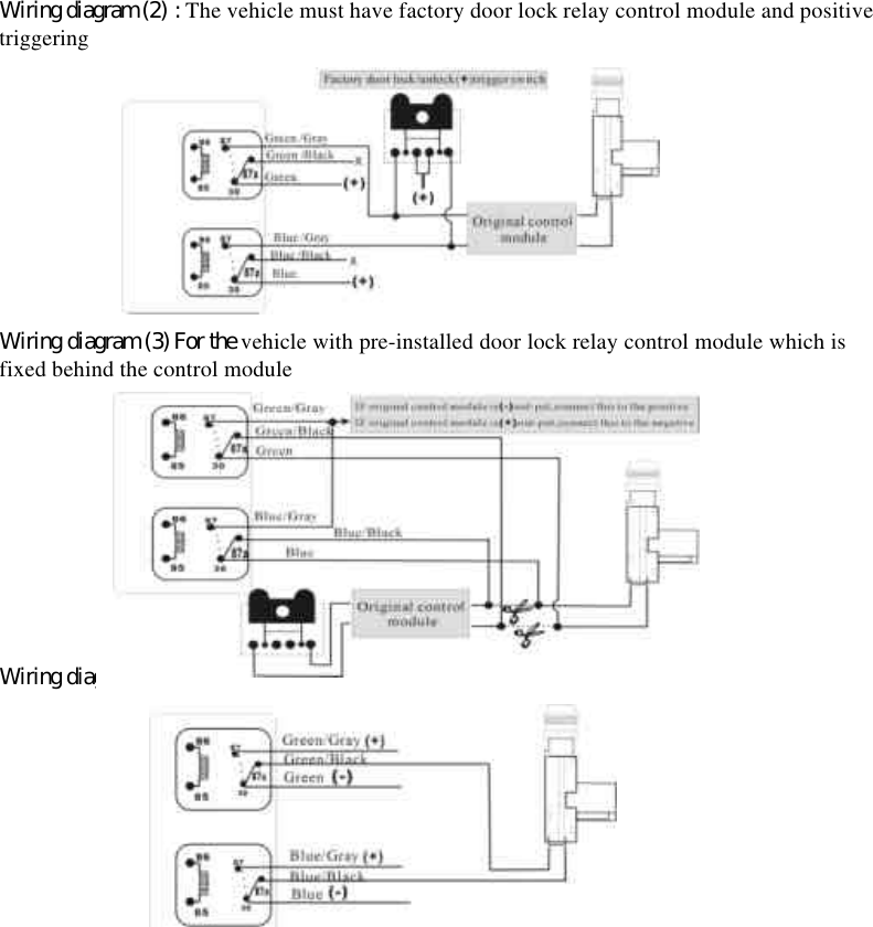
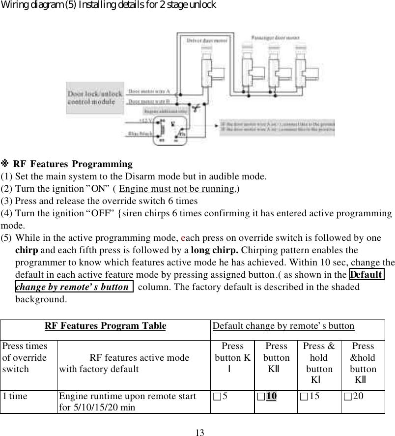
![11External wire loop of main module to differentiate gear modesThis is used in selecting manual or auto transmission gear mode. For auto gear mode, keep thewire loop intact.For manual gear mode, cut this wire loop6 M PIN DOOR LOCK/UNLOCK HARNESSWhile the main system operates lock/unlock action . This harness controls internal relay“unlock ” and “lock ”.※ Program the door lock/unlock output current time as required.[Refer to RF FeaturesProgram Table ,line 9th ]* Lock relay has wire connection as below:1. PIN Blue wire is the common pin for terminal # 30 of the relay2. PIN Blue w/gray wire is the N/O pin for terminal # 87 of the relay3. PIN Blue w/black wire is the N/C pin for terminal # 87a of the relay* Unlock relay has wire connection as below:4. PIN Green wire is the common pin for terminal # 30 of the relay5. PIN Green w/gray wire is the N/O pin for terminal # 87 of the relay6. PIN Green w/black wire is the N/C pin for terminal # 87a of the relayInstallation differs depending on the car factory. Refer to one of the illus. below.Wiring diagram (1) : The vehicle must have factory door lock relay control module and negativetriggering](https://usermanual.wiki/Wintecronics/TR68B/User-Guide-244727-Page-11.png)