Wireless 2000 RF and UWB Technologies 20000310 PAM 3000 Bed Sensor Panel User Manual 100 100 19 04
Wireless 2000 RF & UWB Technologies Ltd. PAM 3000 Bed Sensor Panel 100 100 19 04
Contents
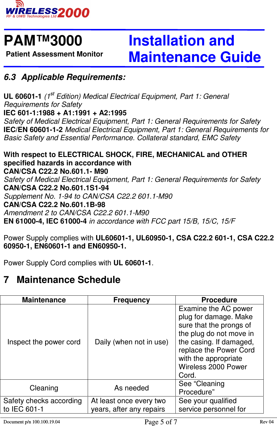
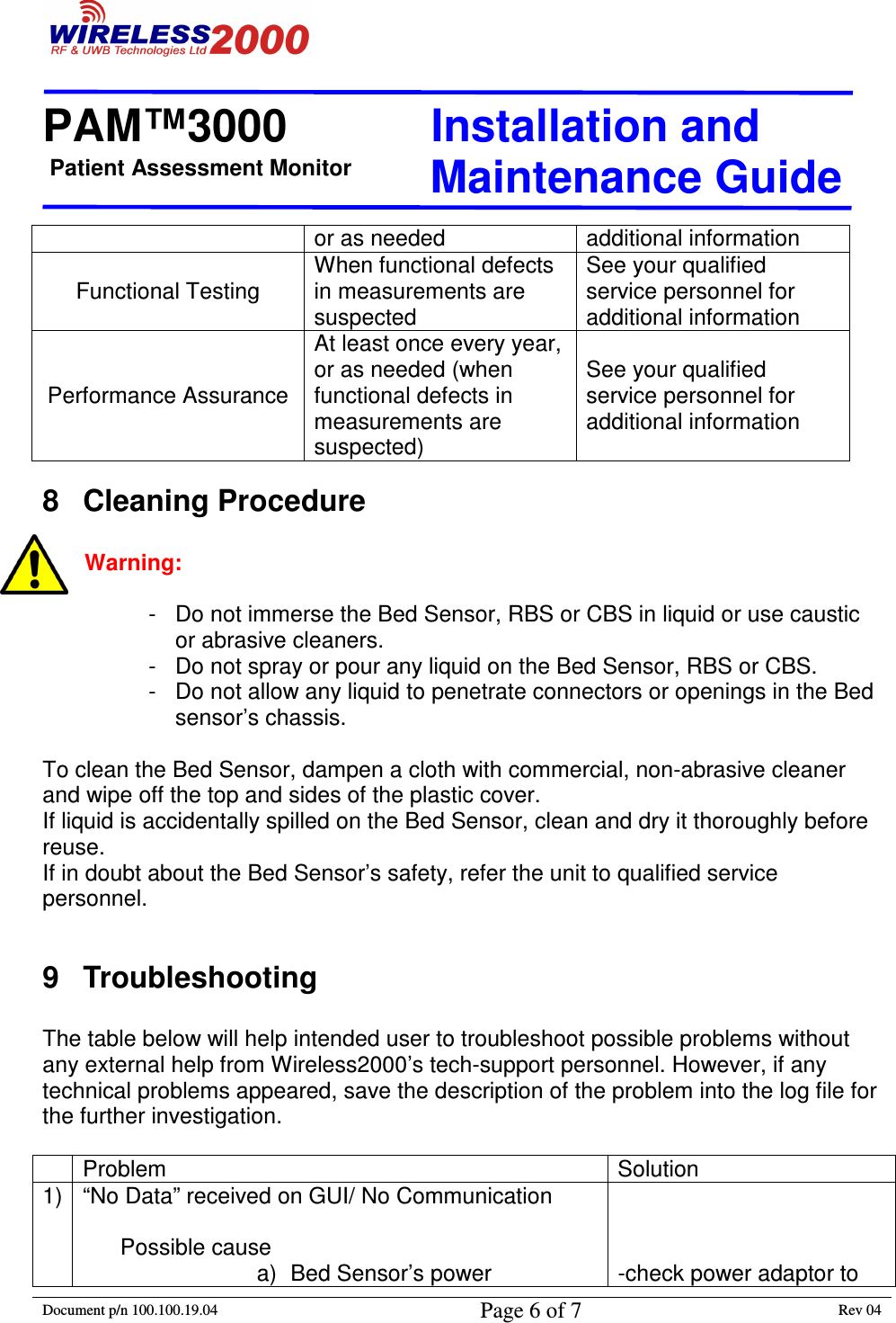
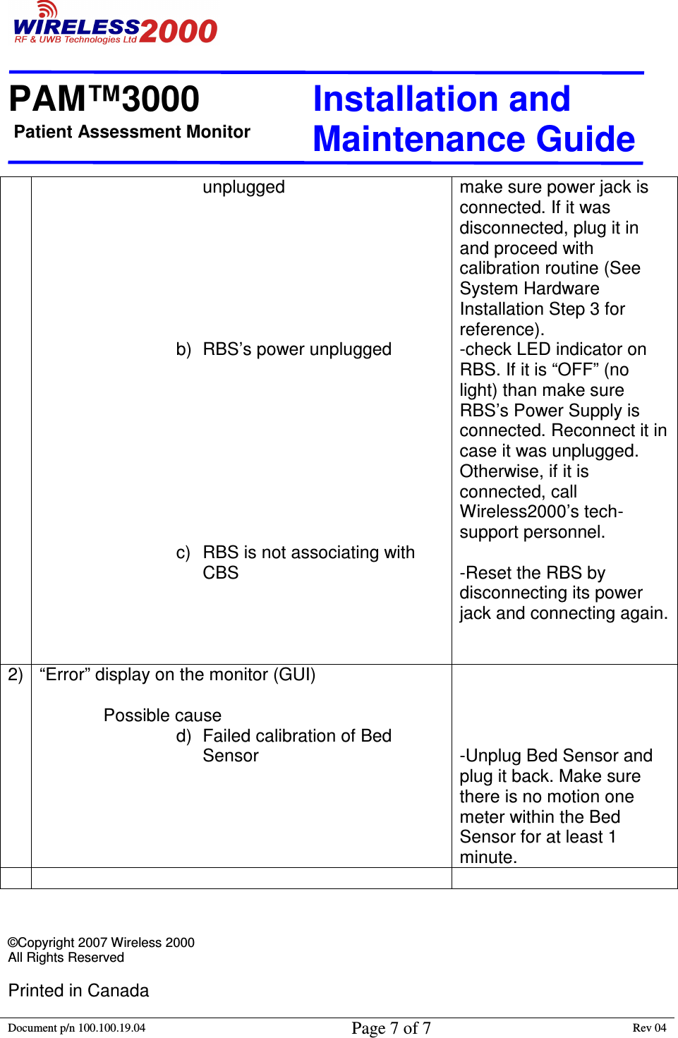
- 1. Instalation and Maintenance Guide
- 2. Instructions For Use
- 3. Instruction For Use
Instalation and Maintenance Guide