Wireless 2000 RF and UWB Technologies 20000310 PAM 3000 BED SENSOR PANEL User Manual 100 100 20 03
Wireless 2000 RF & UWB Technologies Ltd. PAM 3000 BED SENSOR PANEL 100 100 20 03
Contents
- 1. Instalation and Maintenance Guide
- 2. Instructions For Use
- 3. Instruction For Use
Instruction For Use

Model PAM™3000
Patient Assessment Monitor
Document P/N 100.100.20.03
Page 1 of 9
Rev 03
PAM™3000
I
NSTRUCTIONS
F
OR
U
SE
APPLICATION: Patient Assessment Monitor
PRODUCT NAME PAM™3000
PRODUCT P/N: 100.100.10.00
Revision’s History
Originator Approved Rev
Date Comments
E. Gavrilovich 00 08.03.2006 Preliminary draft
Eli A E. Gavrilovich 01 07.04.2008
Rev history, Notes and FCC
information added.
Eli A E. Gavrilovich 02 14.07.2008
Table of contents added
Eli A E. Gavrilovich 03 12.08.2008
FCC Regulatory Note added.
CCS Note added (RA input).
Proprietary Information
This document contains proprietary information which is protected by copyright. All rights reserved. Reproduction, adaptation,
or translation without prior written permission is prohibited, except as allowed under the copyright laws.
Wireless 2000 RF & UWB Technologies Ltd.
2421 Alpha Avenue
Burnaby, BC, V5C 5L2
Canada

Model PAM™3000
Patient Assessment Monitor
Document P/N 100.100.20.03
Page 2 of 9
Rev 03
Table of Contents
1 Preface……………………………………………………………………………………3
2 Introduction………………………………………………………………………………3
2.1 System Description .................................................................................................... 4
3 Intended Use……………………………………………………………………………..4
4 Intended Users…………………………………………………………………………...5
5 Safety Information……………………………………………………………………….5
6 Managing Patients………………………………………………………………………..6
6.1 Admission Procedure ................................................................................................. 6
6.2 Alerts (red) ................................................................................................................. 7
6.3 Flashing numeric ........................................................................................................ 7
6.4 Warnings (yellow) ...................................................................................................... 7
6.5 Nurse call systems ...................................................................................................... 7
6.6 Viewing Individual Alarm Limits .............................................................................. 7
6.7 Screen Display Layout ............................................................................................... 8
6.8 Understanding the Screen Display ............................................................................. 9

Model PAM™3000
Patient Assessment Monitor
Document P/N 100.100.20.03
Page 3 of 9
Rev 03
1 Preface
The Instructions For Use are for clinical professionals using the
PAM™3000 system and provide basic operation overview of the
system and its functions.
Familiarize yourself with all instructions including alerts and warnings
before starting to monitor patients.
Read and keep the Installation and Maintenance Guide that comes with the
system, as it contains important information about care and cleaning that is not
repeated here.
In these Instructions For Use:
• A flashing alert (red) alerts you to a potential serious outcome, adverse event or
safety hazard.
• A warning (yellow) alerts you to where special care might be necessary for the
safe and effective use of the product.
Failure to observe a warning may result in minor or moderate personal injury and
possibly a remote risk of more serious injury.
• System refers to the entire Patient Assessment Monitor (PAM™3000) system.
• Display refers to the physical PC monitor. Terms Display Screen and Screen refer
to everything you see on PC monitor’s display, such as measurements, alarms,
patient data and so forth.
2 Introduction
The PAM™3000 Patient Assessment Monitor measures heart rate, respiration rate,
duration of presence or absence of patient in bed, and duration of movement or lack
of movement of patient in bed. No electrodes need to be attached to the patient’s
body to monitor these functions. The data from the Bed Sensor are sent wirelessly to
the Display Monitor located at the nursing station. System alerts from Display
Monitor may be transmitted to pocket pagers and/or wireless handsets.
Model PAM™3000
Patient Assessment Monitor
Document P/N 100.100.20.03
Page 4 of 9
Rev 03
2.1 System Description
The PAM™3000 system consists of Bed Sensor Panel ( BSP P/N 200.003.10.00)
placed under the mattress of the patient's bed, one or more Repeater Base Stations
(RBSP/N 200.001.10.02) that transmits the digitized patient heart beat data,
respiration data and alert condition information to the Central Base Station (CBS P/N
200.002.10.01). The CBS unit is plugged into a Central Computer Station (CCS P/N
200.008.10.00) typically located at the nursing station. The heart rate and respiration
rate data, bed occupancy data and the alerts generated by system are displayed on
the monitor of the CCS. Alerts are also relayed to nurses’ pagers.
The Bed Sensor is for use ONLY with Wireless2000 Power Supply p/n 375.001.10.00.
Use CCS for monitoring purposes only. Do not install any additional programs or
applications.
3 Intended Use
The PAM™3000 system is intended to measure heart rate and respiration rate in
adult patients, in a general care hospital environment including nursing homes. The
system will also monitor presence or absence of a patient in bed (bed exit).
PAM™3000 is
NOT
for Critical Use.
PAM™3000 should be operated only in environmental conditions specified in PAM™3000
Technical Specification (100.100.22.03). The operating temperature should not exceed
+10°C to +40°C
Model PAM™3000
Patient Assessment Monitor
Document P/N 100.100.20.03
Page 5 of 9
Rev 03
4 Intended Users
The intended users of the PAM™3000 system are clinical professionals within
general care hospitals including nursing homes.
FCC Regulatory Note per FCC Part 15.517
This equipment may only be operated indoors. Operation outdoors is in violation of 47 U.S.C. 301
and could subject the operator to serious legal penalties.
5 Safety Information
COMPLIES WITH:
- UL 60601-1 Medical Electrical Equipment, Part 1: General Requirements for Safety
- IEC 601-1:1988 + A1:1991 + A2:1995
- CSA C22.2 No 601.1-M90
- CSA C22.2 No 601.1-S1-94
- CSA C22.2 No 601.1-B-98
- IEC/EN 60601-1-2 Medical Electrical Equipment
- FCC Part 15/B
- FCC Part 15/C 15.247
- FCC Part 15/F 15.517
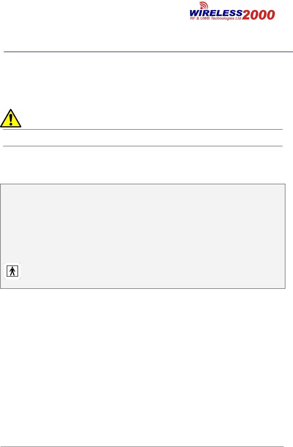
The Label must bear a symbol of Type BF APPLIED PART (Reference IEC 60417-5333):
IEC 60601-1 Patient Applied Part for devices that have conductive contact with the patient, or
have applied parts that are fixed in medium or long term contact with the patient.
Model PAM™3000
Patient Assessment Monitor
Document P/N 100.100.20.03
Page 6 of 9
Rev 03
6 Managing Patients
6.1 Admission Procedure
The monitor starts collecting physiological data and trends as soon as a patient lies
in the bed. However, since all monitoring is done remotely with no display of data at
the patient’s bed, it is important to admit patients properly so that you can identify
your patient on the Display Screen at the nursing station, on recordings, reports, and
communication devices such as pagers, wireless handsets etc.
During admission you enter data such as the safety limits that apply for some
measurements and the alarm limit ranges, the monitor needs to safely and
accurately monitor patients.
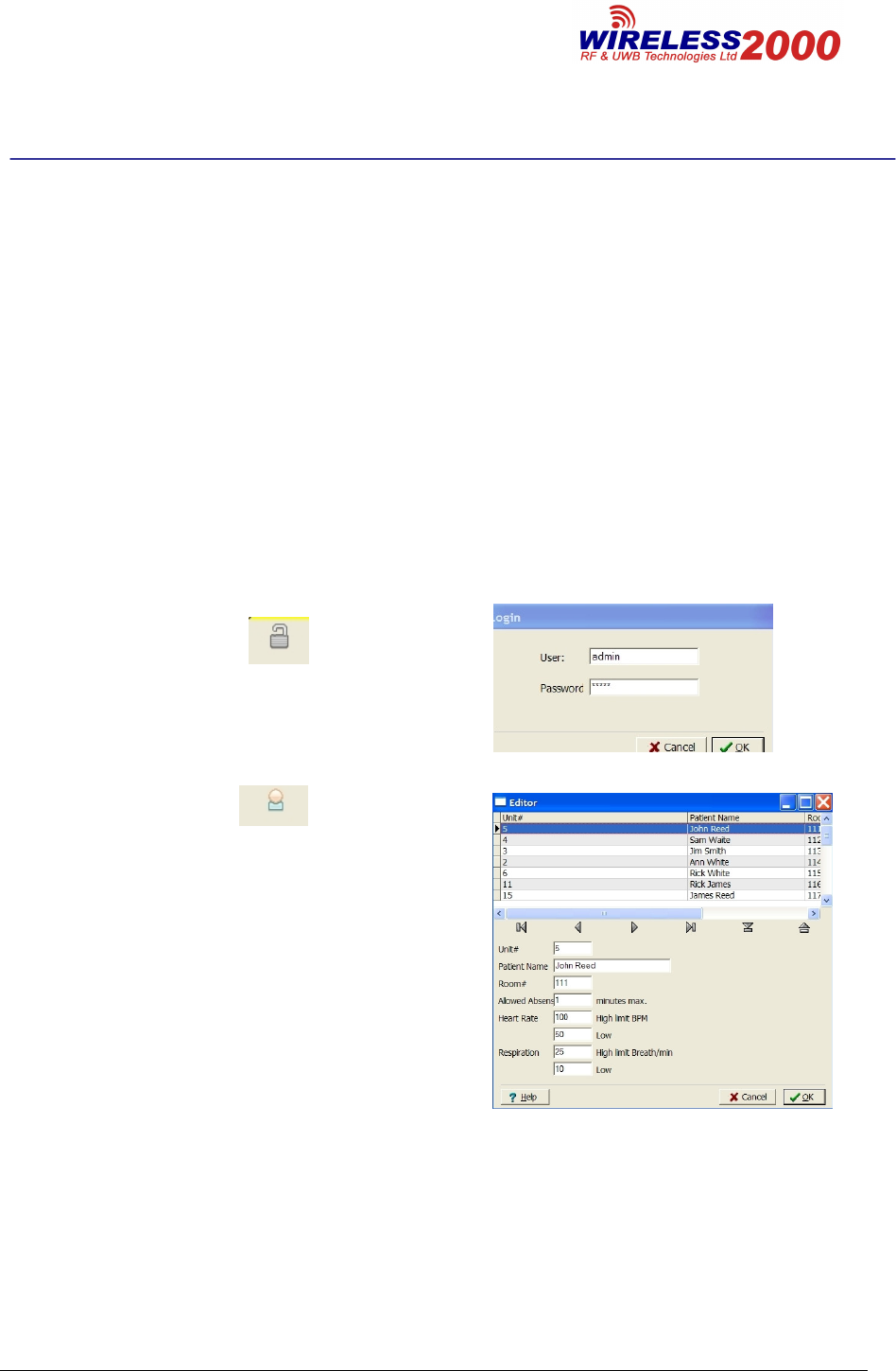
To admit a patient,
1. Select Login Icon
2. Log in using your name and password
(Fig.1_a).
Fig.1_a
3. Select Admit icon
4. In the Unit # window (See Fig.1_b) fill in
the serial number of the Bed Sensor.
5. Fill in Patient Name, Room #, allowed
absence limit, limits for highest and lowest
allowed Heart and Respiration Rate, time
limit for continuous movement and time
limit for continuous absence of movement.
6. Repeat for every patient to be admitted.
Confirm by pressing “OK”.
Fig.1_b

Model PAM™3000
Patient Assessment Monitor
Document P/N 100.100.20.03
Page 7 of 9
Rev 03
6.2 Alerts (red)
A flashing word Alert will appear inside the Status Sector (#4, Fig.3) and the sector’s
color will change to red when one of pre-set limits for heart rate, respiration rate,
absence of patient from the bed, allowed motion or absence of motion is exceeded.
6.3 Flashing numeric
The numeric of the measurement (#8 and #10, Fig.3) at alarm condition will change
color to red and will start flashing.
6.4 Warnings (yellow)
• A word Wait… will appear inside the Status Sector (#4, Fig.3) when unit is
undergoing self-calibration routine. The brief display of this warning requires
no action from the medical personnel. If this warning stays on for longer than
30 seconds, the maintenance personnel must be notified.
• A phrase No Data will appear inside the Status Sector (#4, Fig.3) when
stream of data from bed sensor was suddenly interrupted. This can be
caused by either a) unplugging the bed sensor that resulted in the power loss
to the sensor or b) failure of one or more of the system components such as
bed sensor, power supply, RBS or CBS. This warning requires checking the
system by the maintenance personnel.
6.5 Nurse call systems
If configured to do so, alarms and warnings will be indicated on any device
connected to the Nurse Call relay.
6.6 Viewing Individual Alarm Limits
You can see the Alarm Limits set for each measurement under the measurement
numeric on the main screen in both small and large patient displays.
You can also see Alarm Limits in the Unit # window of the setup menu.
Model PAM™3000
Patient Assessment Monitor
Document P/N 100.100.20.03
Page 8 of 9
Rev 03
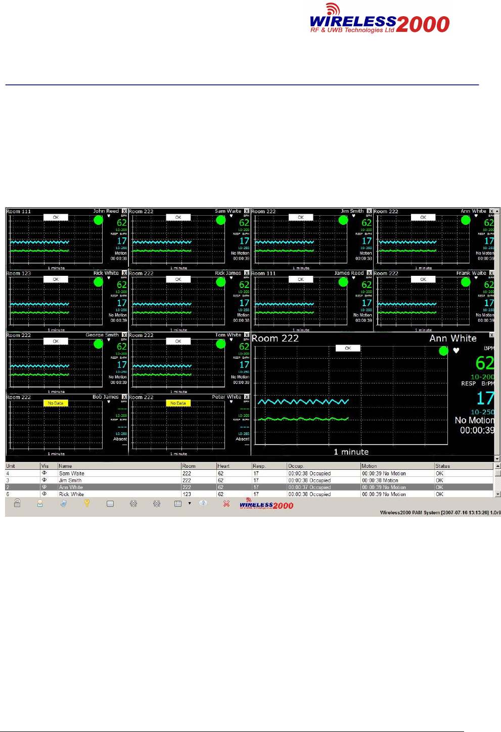
6.7 Screen Display Layout
The Screen Display (See Fig.2) designed to display vital signs information of up to
12 patients simultaneously. Their information is displayed in small windows. It is also
possible to watch one selected patient’s data in the larger window. Double-click on
small window in order to display this patient’s data in the large window.
Fig.2
Model PAM™3000
Patient Assessment Monitor
Document P/N 100.100.20.03
Page 9 of 9
Rev 03
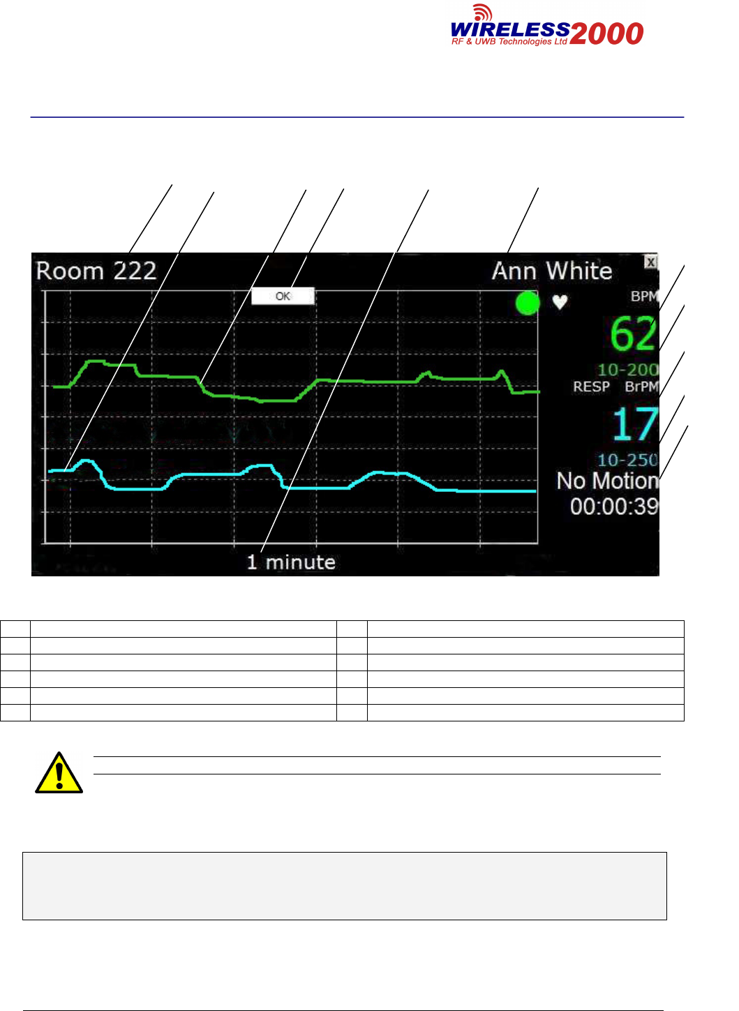
6.8 Understanding the Screen Display
1 2 3 4 5 6
Fig.3
1 Room Number 7 Heart Rate Reading (beats/min)
2 Respiration trend line 8 Heart Rate preset limits for specific patient
3 Heart Rate tend line 9 Respiration Rate reading
4 Status Indicator Sector 10
Respiration Rate preset limits for specific patient
5 Trend line scale (1, 4, 8 or 30 min, 1 hr, 4 hrs) 11
Elapsed Time (motion or no motion)
6 Patient Name 12
Caution: Federal law restricts this device to sale by or on the order of a physician
©Copyright 2007 Wireless 2000
All Rights Reserved
Printed in Canada
7
8
9
10
11