Wireless Matrix 907-FNN-A Wireless Telemetry Unit with RIM 802 DataTAC Radio User Manual TPacManual
Wireless Matrix Corporation Wireless Telemetry Unit with RIM 802 DataTAC Radio TPacManual
UserManual.wiki
>
Wireless Matrix
>
907 FNN A User Manual
Users Manual
Navigation menu
Upload a User Manual
Namespaces
Wiki Guide
HTML
PDF
Info
Views
User Manual
Discussion / Help
Navigation

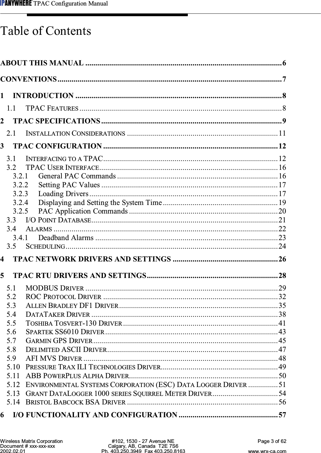


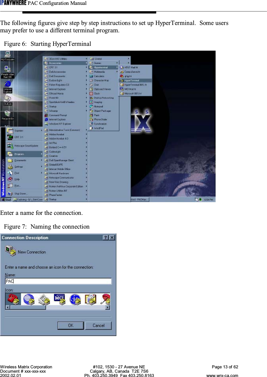

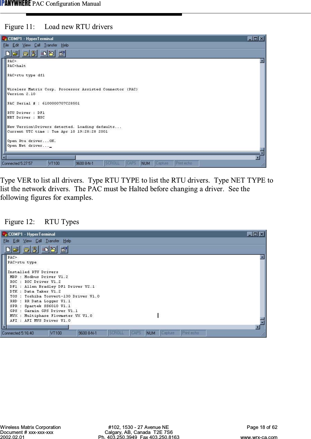

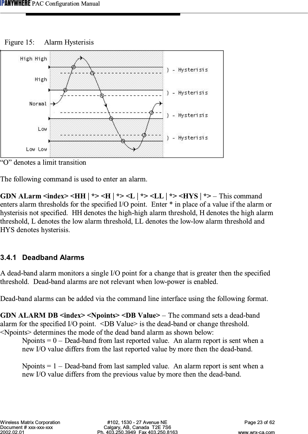
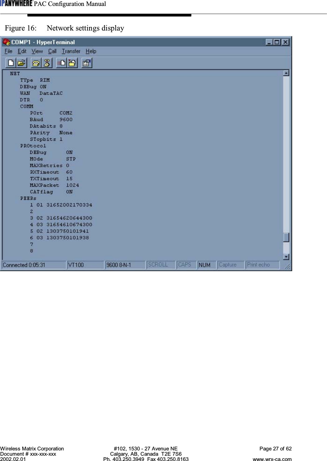
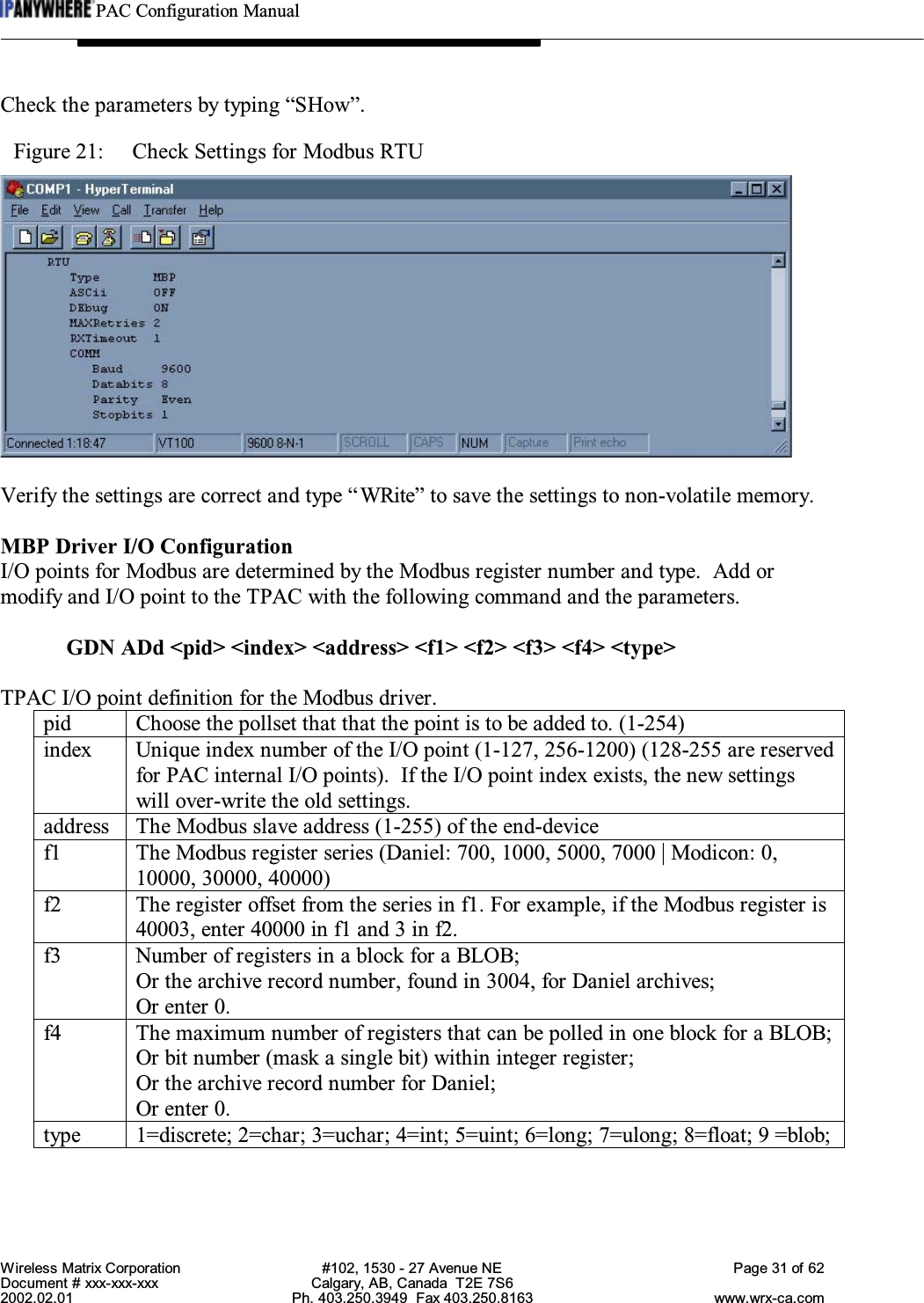

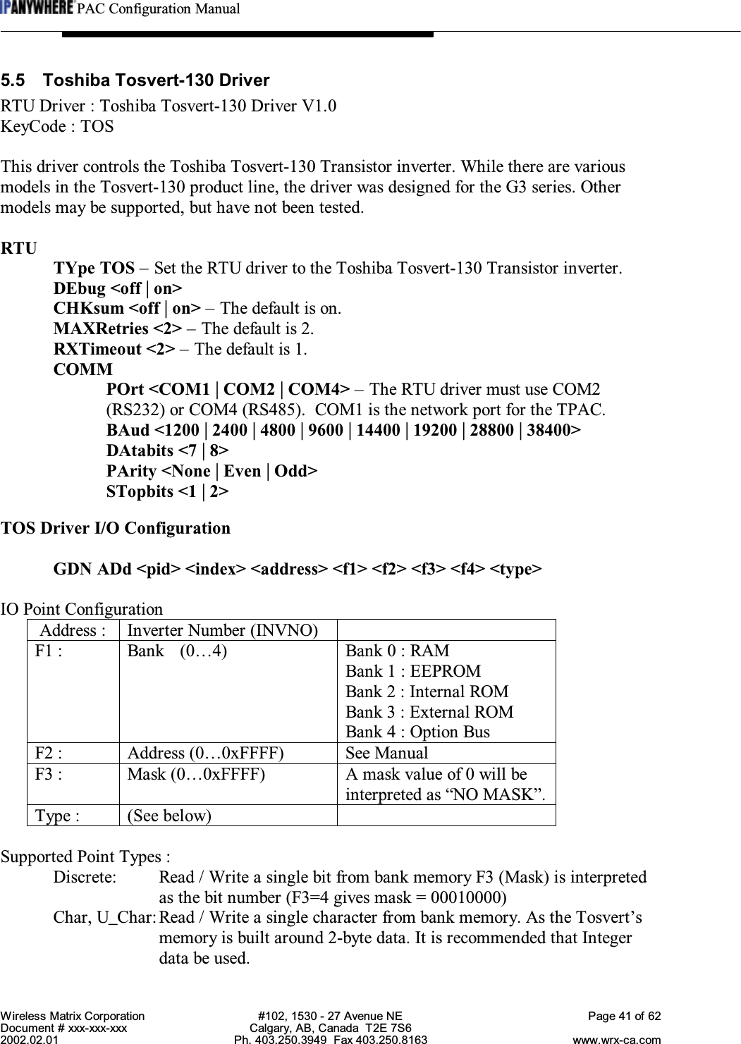
![PAC Configuration ManualWireless Matrix Corporation #102, 1530 - 27 Avenue NE Page 39 of 62Document # xxx-xxx-xxx Calgary, AB, Canada T2E 7S62002.02.01 Ph. 403.250.3949 Fax 403.250.8163 www.wrx-ca.comChannel TypesANALOG INPUTS:Channel ModifiersType Measurement Description Command F2 F3 F4 0 Voltage no zero correction V - - Note 1 1 Voltage zero correction VNC - - Note 1 2 Current w/ external shunt I - - Note 1 3 Current 4-20mA current loop L - - Note 1 4 Resistance by 2,3,or 4 wiremethodR--Note 1 5 Conductivity by 2,3,or 4 wiremethodCO - - Note 1 6 Bridge 4-wire, quarter, half,fullBGI - - Note 1 7 Radiometric 4&6 wire bridges BGV - - Note 1 8 Temperature Thermocouple T[c] Note2a-Note 1 9 Temperature Platinum RTD PT[n] Note2b-Note 110 Temperature Nickel RTD NI - - Note 111 Temperature Copper RTD CU - - Note 112 Temperature YS Series YS[n] Note2b-Note 113 Temperature AD Series AD[n] Note2b-Note 114 Temperature LM Series LM[n] Note2b-Note 115 Temperature TMP Series TMP[n] Note2b-Note 116 Temperature Diode Type DIODE - - Note 1Note 1: F4 selects the channel usage0 : Basic connection i.e.: 1V1 : Positive terminal connection i.e.: 1+V2 : Negative terminal connection i.e.: 1-V3 : Default excitation applied i.e.: 1*V4 : Return common terminal i.e.: 1#VNote 2: F2 selects temperature sensor sub-type2a : Selects Thermocouple type {1=A, 2=B, 3=C, 4=D,…}2b : Selects sensor sub-type number {Addr=5, F1=12, F2=16 } = “5YS16”](https://usermanual.wiki/Wireless-Matrix/907-FNN-A/User-Guide-226718-Page-40.png)

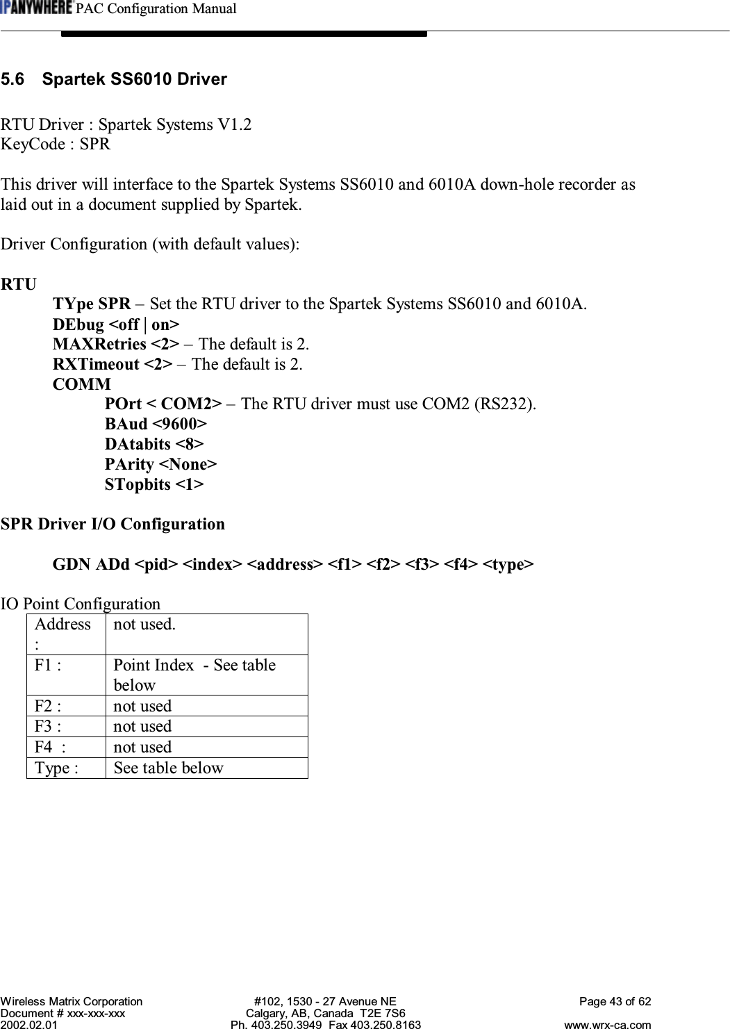


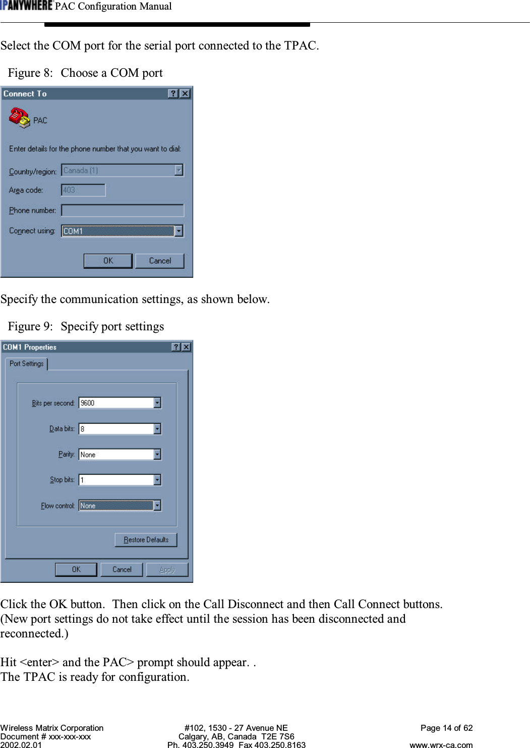
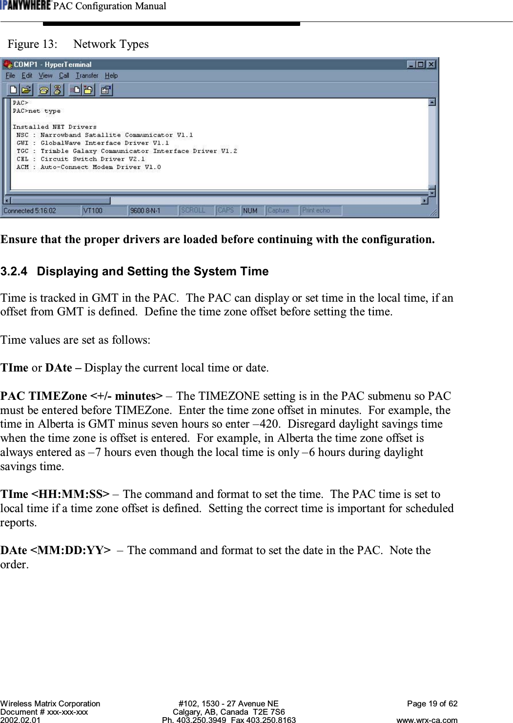
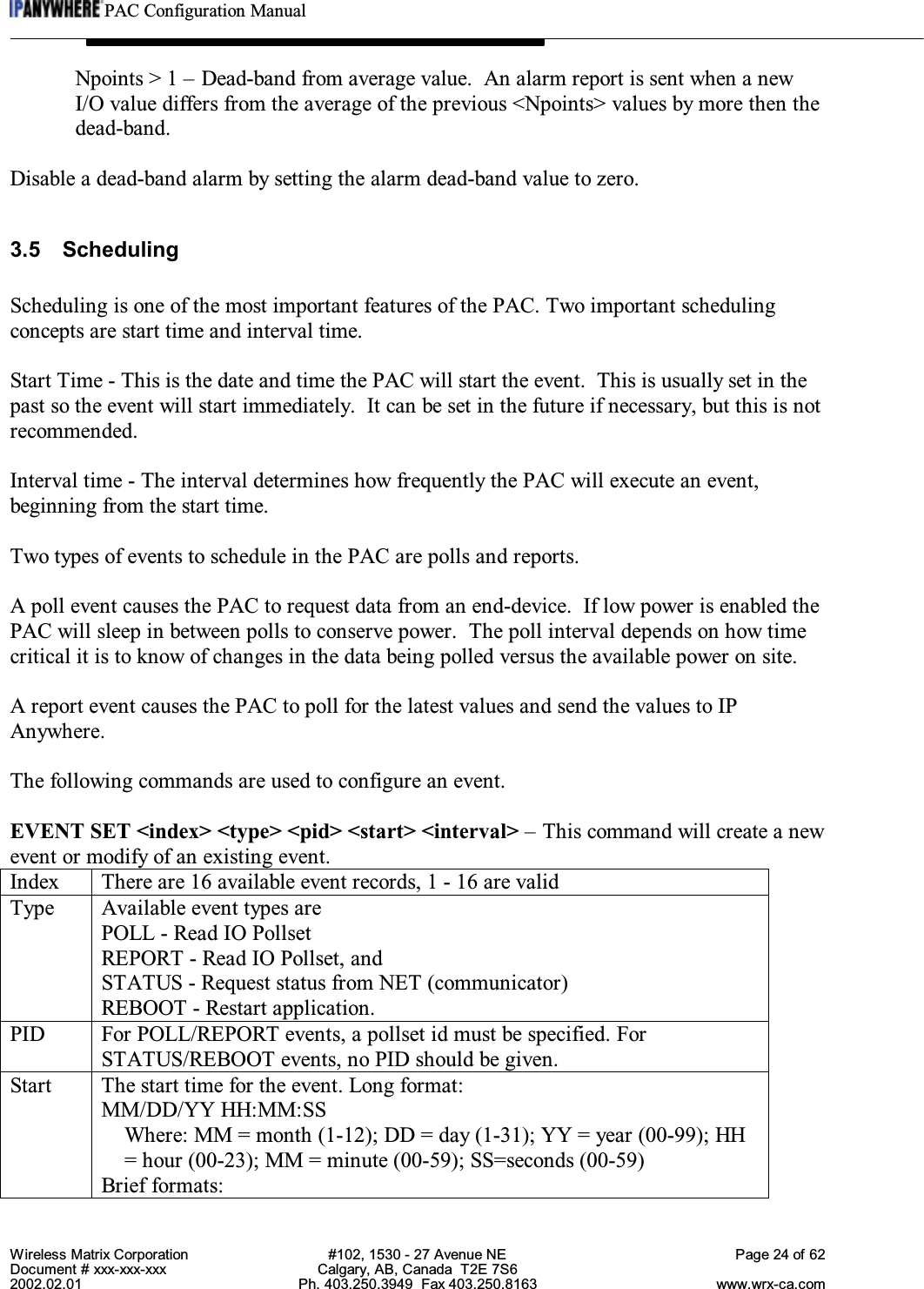
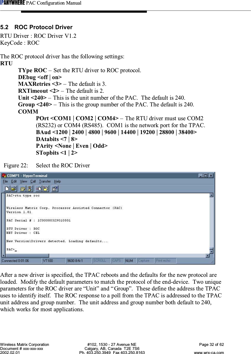
![PAC Configuration ManualWireless Matrix Corporation #102, 1530 - 27 Avenue NE Page 49 of 62Document # xxx-xxx-xxx Calgary, AB, Canada T2E 7S62002.02.01 Ph. 403.250.3949 Fax 403.250.8163 www.wrx-ca.com5.10 Pressure Trax ILI Technologies DriverRTU Driver : ILI Technologies : PressureTrax V1.1KeyCode : PRTDriver configuration:RTUTYpe PRT – Set the RTU driver to the PressureTrax.DEbug <off | on>RXTimeout <8> – The default is 5.MAXRetries <2> – The default is 2.COMMPOrt < COM2> – The RTU driver must use COM2 (RS232).BAud <4800>DAtabits <8>PArity <None>STopbits <1>PRT Driver I/O ConfigurationGDN ADd <pid> <index> <address> <f1> <f2> <f3> <f4> <type>IO Point ConfigurationAddress:not used.F1 : Point Index - See table belowF2 : not usedF3 : not usedF4 : not usedType : See table belowF1 Type Data form PRT1 Uint Current raw pressure data Channel 12 Uint Current raw pressure data Channel 23 Uint Current raw pressure data Channel 34 Blob EEPROM Data block [ 128 bytes]5 Blob SRAM Block #0 [1024 bytes]6 Blob SRAM Block #1 [1024 bytes]](https://usermanual.wiki/Wireless-Matrix/907-FNN-A/User-Guide-226718-Page-50.png)


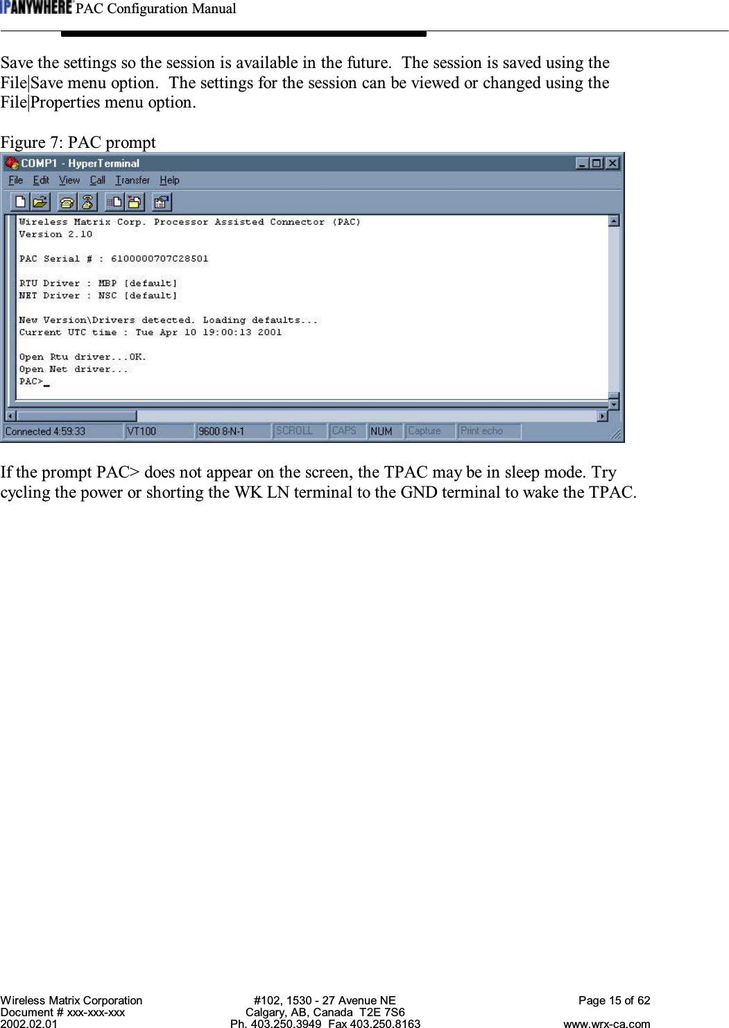
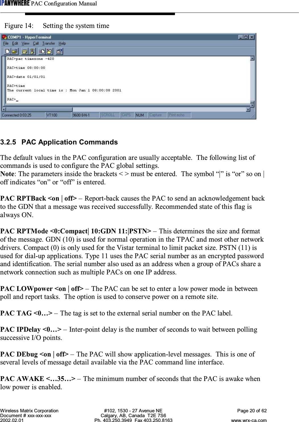
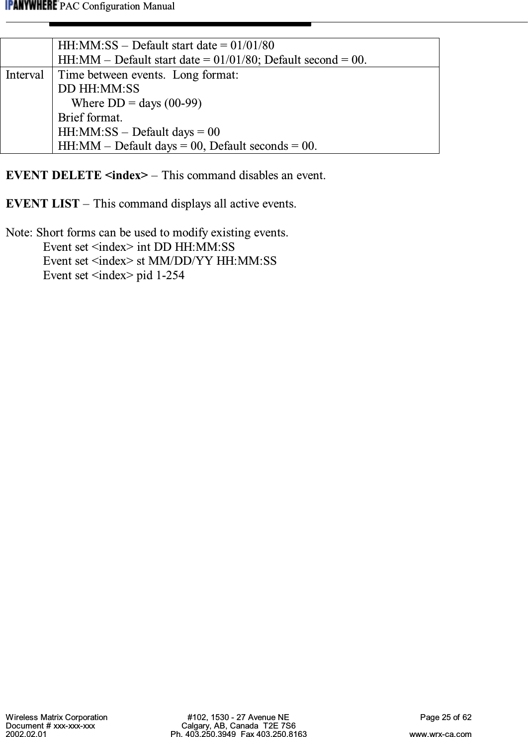
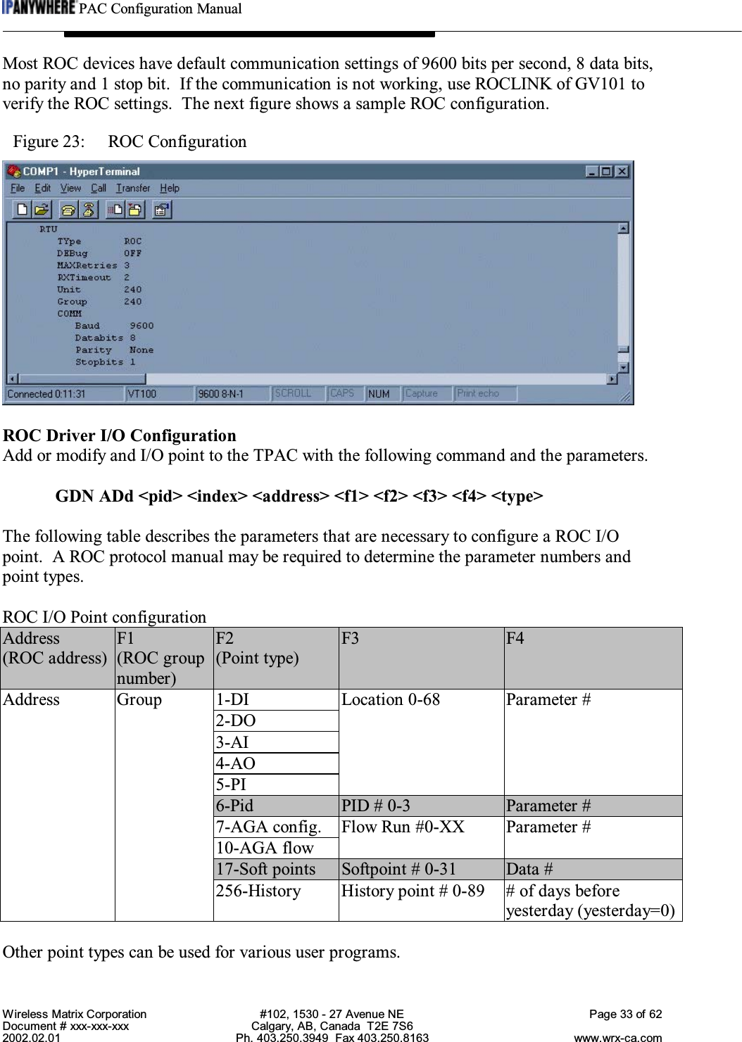
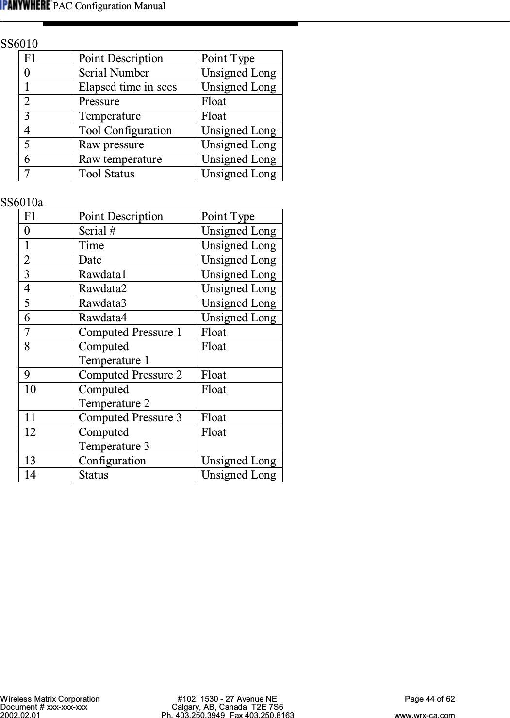
![PAC Configuration ManualWireless Matrix Corporation #102, 1530 - 27 Avenue NE Page 54 of 62Document # xxx-xxx-xxx Calgary, AB, Canada T2E 7S62002.02.01 Ph. 403.250.3949 Fax 403.250.8163 www.wrx-ca.com5.13 Grant DataLogger 1000 series Squirrel Meter DriverRTU Driver : 1000 Squirrels Datalogger V1.0KeyCode : 1KSThis driver will interface to the Grant “1000 Squirrels” Datalogger.Driver configuration:RTUTYpe 1KS – Set the RTU driver to the Grant data logger.DEbug <off | on>RXTimeout <2000>MAXRetries <2>COMMPOrt < COM2> – The RTU driver must use COM2 (RS232).BAud <9600>DAtabits <8>PArity <None>STopbits <1>IKS Driver I/O ConfigurationGDN ADd <pid> <index> <address> <f1> <f2> <f3> <f4> <type>IO Point ConfigurationAddress : not usedF1 : CommandF2 : see below.F3 : see belowF4 : not used.Type : see below.Channel DataF1 72 - Channel DataF2 Channel # [1…n]F3 Event bit [0…n] Signal channel only.F4 not used.Type Float - Calculated using channel configuration dataInt - Raw data.UInt - Pulse counter channels.Discrete - Event bit (use F3 to determine bit offset)](https://usermanual.wiki/Wireless-Matrix/907-FNN-A/User-Guide-226718-Page-55.png)