Wireless Matrix 907-FNN-A Wireless Telemetry Unit with RIM 802 DataTAC Radio User Manual TPacManual
Wireless Matrix Corporation Wireless Telemetry Unit with RIM 802 DataTAC Radio TPacManual
Users Manual

Wireless Matrix Corporation #102, 1530 - 27 Avenue NE Page 1 of 62
Document # xxx-xxx-xxx Calgary, AB, Canada T2E 7S6
2002.02.01 Ph. 403.250.3949 Fax 403.250.8163 www.wrx-ca.com
Terrestrial Processor Assisted Connector
Installation and Configuration Manual
Version 2.2X

TPAC Configuration Manual
Wireless Matrix Corporation #102, 1530 - 27 Avenue NE Page 2 of 62
Document # xxx-xxx-xxx Calgary, AB, Canada T2E 7S6
2002.02.01 Ph. 403.250.3949 Fax 403.250.8163 www.wrx-ca.com
IP Anywhere TPAC Configuration Manual
Copyright © 2002 Wireless Matrix. All rights reserved.
Printed in Canada
This document is proprietary to Wireless Matrix Corporation. Do not reproduce, use or disclose without
permission. We have made every effort to ensure the accuracy of all information contained in this document.
However, Wireless Matrix Corporation makes no expressed or implied warranty or representation based upon
the enclosed information

FCC RF EXPOSURE INFORMATION
In August 1996 the Federal Communications Commission (FCC) of the United States
with its action in Report and Order FCC 96 -326 adopted an updated safety standard for
human exposure to radio frequency (RF) electromagnet ic energy emitted by FCC
regulated transmitters. Those guidelines are consistent with the safety standard
previously set by both U.S. and international standards bodies. The design of this
device complies with the FCC guidelines and these international s tandards.
Use only the supplied or an approved antenna. Unauthorized antennas, modifications,
or attachments could impair call quality, damage the phone, or result in violation of
FCC regulations.
All persons must be at least 20 cm from the antenna w hen the transmitter is operating
and must not be co -located or operating in conju nction with any other antenna or
transmitter in order to comply with FCC RF exposure requirements.
For more information about RF exposure, please visit the FCC website at www.fcc.gov
Please read this information before use

TPAC Configuration Manual
Wireless Matrix Corporation #102, 1530 - 27 Avenue NE Page 3 of 62
Document # xxx-xxx-xxx Calgary, AB, Canada T2E 7S6
2002.02.01 Ph. 403.250.3949 Fax 403.250.8163 www.wrx-ca.com
Table of Contents
ABOUT THIS MANUAL ...................................................................................................6
CONVENTIONS.................................................................................................................7
1 INTRODUCTION ........................................................................................................8
1.1 TPAC FEATURES ......................................................................................................8
2 TPAC SPECIFICATIONS...........................................................................................9
2.1 INSTALLATION CONSIDERATIONS ............................................................................11
3 TPAC CONFIGURATION ........................................................................................12
3.1 INTERFACING TO A TPAC........................................................................................12
3.2 TPAC USER INTERFACE..........................................................................................16
3.2.1 General PAC Commands .................................................................................16
3.2.2 Setting PAC Values .........................................................................................17
3.2.3 Loading Drivers...............................................................................................17
3.2.4 Displaying and Setting the System Time..........................................................19
3.2.5 PAC Application Commands ...........................................................................20
3.3 I/O POINT DATABASE..............................................................................................21
3.4 ALARMS .................................................................................................................22
3.4.1 Deadband Alarms ............................................................................................23
3.5 SCHEDULING...........................................................................................................24
4 TPAC NETWORK DRIVERS AND SETTINGS .....................................................26
5 TPAC RTU DRIVERS AND SETTINGS..................................................................28
5.1 MODBUS DRIVER .................................................................................................29
5.2 ROC PROTOCOL DRIVER ........................................................................................32
5.3 ALLEN BRADLEY DF1 DRIVER................................................................................35
5.4 DATATAKER DRIVER ..............................................................................................38
5.5 TOSHIBA TOSVERT-130 DRIVER ..............................................................................41
5.6 SPARTEK SS6010 DRIVER .......................................................................................43
5.7 GARMIN GPS DRIVER .............................................................................................45
5.8 DELIMITED ASCII DRIVER......................................................................................47
5.9 AFI MVS DRIVER ..................................................................................................48
5.10 PRESSURE TRAX ILI TECHNOLOGIES DRIVER...........................................................49
5.11 ABB POWERPLUS ALPHA DRIVER...........................................................................50
5.12 ENVIRONMENTAL SYSTEMS CORPORATION (ESC) DATA LOGGER DRIVER ...............51
5.13 GRANT DATALOGGER 1000 SERIES SQUIRREL METER DRIVER.................................54
5.14 BRISTOL BABCOCK BSA DRIVER ............................................................................56
6 I/O FUNCTIONALITY AND CONFIGURATION ..................................................57

TPAC Configuration Manual
Wireless Matrix Corporation #102, 1530 - 27 Avenue NE Page 4 of 62
Document # xxx-xxx-xxx Calgary, AB, Canada T2E 7S6
2002.02.01 Ph. 403.250.3949 Fax 403.250.8163 www.wrx-ca.com
6.1 I/O1-I/O4 ...............................................................................................................58
6.1.1 Analog (1-5V) .................................................................................................58
6.1.2 Analog (4-20mA).............................................................................................58
6.1.3 Digital input.....................................................................................................58
6.2 TIN1 ......................................................................................................................59
6.2.1 Digital (Off, On) ..............................................................................................59
6.2.2 Pulse Counter...................................................................................................59
6.2.3 RPM meter ......................................................................................................60
6.2.4 Frequency Meter (kHz)...................................................................................60
6.3 TEMPERATURE AND PRESSURE ................................................................................61
6.3.1 Temperature in °C............................................................................................61
6.3.2 Barometric Pressure (kPa)................................................................................61
APPENDIX A....................................................................................................................62

PAC Configuration Manual
Wireless Matrix Corporation #102, 1530 - 27 Avenue NE Page v of 62
Document # xxx-xxx-xxx Calgary, AB, Canada T2E 7S6
2002.02.01 Ph. 403.250.3949 Fax 403.250.8163 www.wrx-ca.com
List of Figures
Figure 1: Operating and environmental specifications ..........................................................9
Figure 2: RF Specifications..................................................................................................9
Figure 3: Terminal Blocks (TB1 and TB2)...........................................................................9
Figure 4: TPAC configuration port (3-pin header: J4)........................................................10
Figure 5: TPAC Mechanical Drawing ................................................................................10
Figure 6: Starting HyperTerminal.......................................................................................13
Figure 7: Naming the connection........................................................................................13
Figure 8: Choose a COM port ............................................................................................14
Figure 9: Specify port settings............................................................................................14
Figure 10: Display the version ..........................................................................................17
Figure 11: Load new RTU drivers.....................................................................................18
Figure 12: RTU Types ......................................................................................................18
Figure 13: Network Types ................................................................................................19
Figure 14: Setting the system time ....................................................................................20
Figure 15: Alarm Hysterisis ..............................................................................................23
Figure 16: Network settings display..................................................................................27
Figure 17: Select the Modbus driver..................................................................................29
Figure 18: Configure TPAC for Modbus ASCII................................................................30
Figure 19: Check Settings for Modbus ASCII ...................................................................30
Figure 20: Configure TPAC for Modbus RTU ..................................................................30
Figure 21: Check Settings for Modbus RTU .....................................................................31
Figure 22: Select the ROC Driver .....................................................................................32
Figure 23: ROC Configuration..........................................................................................33

PAC Configuration Manual
Wireless Matrix Corporation #102, 1530 - 27 Avenue NE Page 6 of 62
Document # xxx-xxx-xxx Calgary, AB, Canada T2E 7S6
2002.02.01 Ph. 403.250.3949 Fax 403.250.8163 www.wrx-ca.com
About This Manual
The Terrestrial Processor Assisted Connector (TPAC) Installation and Configuration Manual
will assist the user to understand the fundamentals of TPAC configuration and operation. The
manual assumes that the user has basic knowledge of serial communication, end devices and
electrical installation and wiring.

PAC Configuration Manual
Wireless Matrix Corporation #102, 1530 - 27 Avenue NE Page 7 of 62
Document # xxx-xxx-xxx Calgary, AB, Canada T2E 7S6
2002.02.01 Ph. 403.250.3949 Fax 403.250.8163 www.wrx-ca.com
Conventions
The Terrestrial Processor Assisted Connector will be referred to as the TPAC from this point
forward.
TPAC configuration commands are displayed in bold type followed by < >. The < >
brackets indicate a variable should be entered.
Example: GDN ADd <pid><index><address><f1><f2><f3><f4><type>
The TPAC interface uses minimum truncation. This means that only the letters that are
capitalized need to be entered when programming the TPAC. The TPAC is not case
sensitive. The menu structure in the TPAC configuration contains headings and subheadings.
The command tree will be displayed as follows.
RTU
DEBug OFF
MAXRetries 2
RXTimeout 1
COMM
Baud 9600
DataBits 8
Parity None
StopBits 1
Commands are entered as follows; to change the RTU debug settings type.
RTU DEBug on

PAC Configuration Manual
Wireless Matrix Corporation #102, 1530 - 27 Avenue NE Page 8 of 62
Document # xxx-xxx-xxx Calgary, AB, Canada T2E 7S6
2002.02.01 Ph. 403.250.3949 Fax 403.250.8163 www.wrx-ca.com
1 INTRODUCTION
The terrestrial processor assisted connector (TPAC) is a device that is an interface between
an end-device and the Wireless Matrix IP Anywhere service. A terrestrial communications
medium is an integral part of the TPAC. The term “terrestrial” is used to differentiate the
communication network from a “space” (satellite) network. Examples of terrestrial networks
are the public switched telephone network (PSTN), public cell-based wireless packet data
networks (DataTAC, Mobitex, GPRS, CDPD), public wired packet data networks (Datapac,
the Internet) and private wired and wireless networks.
The TPAC collects data from an end-device such as an RTU or PLC and passes the data to IP
Anywhere using the terrestrial data network. The TPAC can communicate with numerous
end-devices in the device’s native protocol via an RS-232 or RS-485 serial communication
link. RS-422 and other physical layers are supported with converters. The TPAC provides
timed reports, reports by exception and reports on demand.
An I/O point is a measured or stored value in an end-device. The TPAC can read an I/O
point using the device communications protocol. An I/O point can also be internal to the
TPAC or signals on the general-purpose I/O lines on the TPAC. The TPAC stores a list of
I/O points that it needs to access.
1.1 TPAC Features
•The TPAC can communicate with an end device using its native protocol.
•The TPAC has an integral RIM DataTAC transceiver for communications.
•The TPAC can report data on a scheduled interval, real time events or on demand.
•The TPAC responds to a remote “DEMAND POLL” request by reading the current
I/O values from the remote site and sending updated values to the GDN.
•The I/O points and alarm set points can be edited remotely over the communications
network.
•The TPAC can store I/O points in multiple poll sets. Each poll set has its own report
time and interval and can be adjusted remotely.
•The TPAC can minimize power consumption by entering a low power “sleep” mode.
•The TPAC can poll RS-232 and RS485 serial end-devices for I/O points.
•The TPAC can interface directly to transmitters (1-5 volts, 4-20 mA, digital) for I/O.
•During a poll operation the TPAC read the I/O points from a specified poll-set. The
unit will send a report to IP Anywhere if:
•A report is scheduled
•An analog I/O value crosses the preset alarm limits
•An analog I/O value changes by more than a preset dead band
•A discrete value either changes state or transitions to a specific state

PAC Configuration Manual
Wireless Matrix Corporation #102, 1530 - 27 Avenue NE Page 9 of 62
Document # xxx-xxx-xxx Calgary, AB, Canada T2E 7S6
2002.02.01 Ph. 403.250.3949 Fax 403.250.8163 www.wrx-ca.com
2 TPAC Specifications
Figure 1: Operating and environmental specifications
Input voltage 9-28 VDC
Receive current (Vin=12V) 80 mA
Transmit current (Vin=12V) 1 A
Sleep mode current (Vin=12V) 1 mA
Operating temperature -30 to 70 °C
Vibration TBD
Serial ports 3 (2xRS232 + 1xRS485)
Dimensions 200 x 140 x 90 mm (7.9 x 5.5 x 3.5”)
Mounting holes 180 x 93 mm (7.1 x 3.7”)
Weight 2 kg (4.25 lbs.)
Figure 2: RF Specifications
RF network DataTAC
FCC approval (pending) P5I-907-FNN-A
Canada RSS-119 approval (pending) TBD
Transmit frequency range 806 to 821 MHz
Receive frequency range 851 to 870 MHz
Transmit power (Conducted) 60 to 2000 mW (17.8 to 33 dBm)
Antenna gain (transmit band) 1.15 to 2.4 dBi
Maximum ERP 34.2 dBm
Antenna ¼ wave dipole, 868 MHz center frequency
Antenna cable 20 cm (8”) RG174 coax (integral with antenna)
RF connector MMCX
Figure 3: Terminal Blocks (TB1 and TB2)
TB1
Pin
Description TB2
Pin
Description
1 GND: ground 10 COM2T: RS232 transmit
2 + Vin: 9 to 28 VDC 9 COM2R: RS232 receive
3 GND: ground 8 COM2Ring: RS232 ring
4 Wake: ground to wake PAC 7 GND: ground
5 GND: ground 6 COM4B: RS485 B
6 + Vext: source < 200 mA @Vin 5 COM4A: RS485 A
7 GND: ground 4 GND: ground
8 DI/O: discrete input/output 3 TIN1: timer/pulse input
9 I/O1: input/output 2 I/O4: input/output
10 I/O2: input/output 1 I/O3: input/output
PAC Configuration Manual
Wireless Matrix Corporation #102, 1530 - 27 Avenue NE Page 10 of 62
Document # xxx-xxx-xxx Calgary, AB, Canada T2E 7S6
2002.02.01 Ph. 403.250.3949 Fax 403.250.8163 www.wrx-ca.com
Figure 4: TPAC configuration port (3-pin header: J4)
J4
Pin
Description
1 COM2T: RS232 transmit
2 COM2R: RS232 receive
3 GND: ground
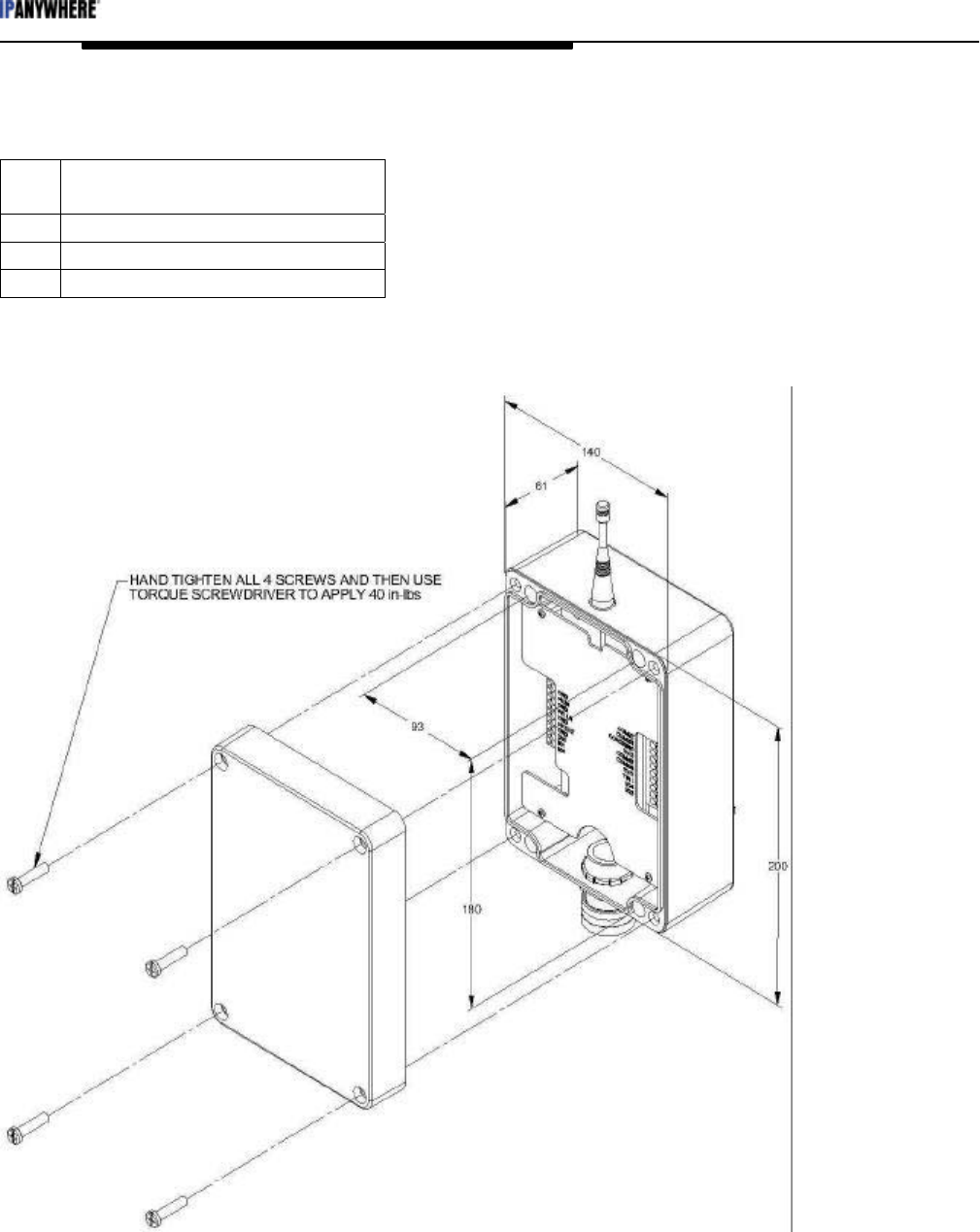
Figure 5: TPAC Mechanical Drawing

PAC Configuration Manual
Wireless Matrix Corporation #102, 1530 - 27 Avenue NE Page 11 of 62
Document # xxx-xxx-xxx Calgary, AB, Canada T2E 7S6
2002.02.01 Ph. 403.250.3949 Fax 403.250.8163 www.wrx-ca.com
2.1 Installation Considerations
Mounting:
•The TPAC has mounting holes beneath the cover of the enclosure. The mounting
holes are spaced 93 x 180 mm. The mounting holes are 7.5 mm in diameter and the
access holes are 11 mm in diameter. The TPAC can be mounted to a panel using
appropriate screws for the panel material.
•The TPAC should be mounted with the antenna vertical on the top of the enclosure.
The conduit entry/cable seal should point down.
•Ensure end devices are within an acceptable distance from the TPAC.
Power:
•The TPAC requires 9-28 VDC to operate. Maximum current draw is 1 A.
•Power is applied at the Vin and GND terminals.
•The metal case of the TPAC must be grounded at one of the mounting holes.
•The TPAC can put itself into a sleep mode to conserve power. The minimum duty
cycle is 30 seconds per day. Current draw in sleep mode is under 1 mA.
Terrestrial network:
•Prior to installing a TPAC with a DataTAC communication module, check the
Motient or Bell Mobility coverage map to ensure the site is in range of the network.
•If the site is near the edge of coverage, a site survey may be necessary to verify
coverage and determine the optimal place to install the TPAC.
•Install the TPAC so there are minimal obstructions between the TPAC and the nearest
network tower. Network towers are concentrated in urban centers.
•There is a small green LED at the top of the TPAC printed circuit board. The LED
will illuminate when the TPAC is in coverage of the network. The TPAC must be
commissioned before the LED will function.
•The TPAC displays network signal strength on the configuration port when it boots.
Other Wiring:
•The serial connection to the end device is made using the terminal blocks for COM2
(RS232) or COM4 (RS485).
•The terminal WK LN can be shorted to ground to manually wake the TPAC from
sleep mode.
•The terminal +V EXT can be used to supply power to an external device. The
voltage is the same as supplied to +V IN. Current is limited to 200 mA. The TPAC
controls whether power is available at the terminal.
•The terminal DI/O can be used as a digital input or output.
•Analog inputs (4-20 mA or 1-5 V) can be wired into the terminals labeled I/O1 to
I/O4. Digital inputs can be wired into the I/O terminals too.
•The terminal TIN1 can be used as a pulse counter, frequency counter or digital input.
•Refer to the wiring diagram that is specific to the application.

PAC Configuration Manual
Wireless Matrix Corporation #102, 1530 - 27 Avenue NE Page 12 of 62
Document # xxx-xxx-xxx Calgary, AB, Canada T2E 7S6
2002.02.01 Ph. 403.250.3949 Fax 403.250.8163 www.wrx-ca.com
3 TPAC Configuration
The TPAC needs to be configured to function properly. The TPAC is shipped with factory
default settings. The configuration can be modified via the communication network or
locally using a programming cable from a PC to the TPAC. A site information sheet should
be prepared prior to configuring the TPAC.
3.1 Interfacing to a TPAC
A Wireless Matrix TPAC programming cable is required to configure the TPAC using a local
PC. The cable is a 3-wire cable with a D9 female on one end and a 3-position Molex
connector on the other end. Connect the 3-position connector to the 3-position header (J4) on
the TPAC interface board. Connect the D9 female connector to the serial port on a PC.
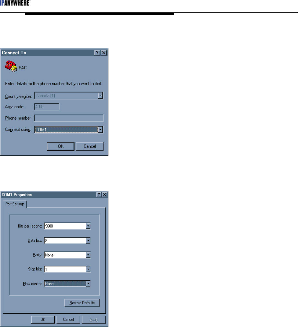
Start a PC terminal emulation program, such as HyperTerminal. Specify the local serial port
and set the communication parameters to 9600 bits/s, 8 data-bits, no parity, and no flow
control. Disconnect from the port and then reconnect to the port so the settings take affect.
(See the next section for setting up HyperTerminal).
Apply power to the TPAC to begin the configuration session.
PAC Configuration Manual
Wireless Matrix Corporation #102, 1530 - 27 Avenue NE Page 13 of 62
Document # xxx-xxx-xxx Calgary, AB, Canada T2E 7S6
2002.02.01 Ph. 403.250.3949 Fax 403.250.8163 www.wrx-ca.com
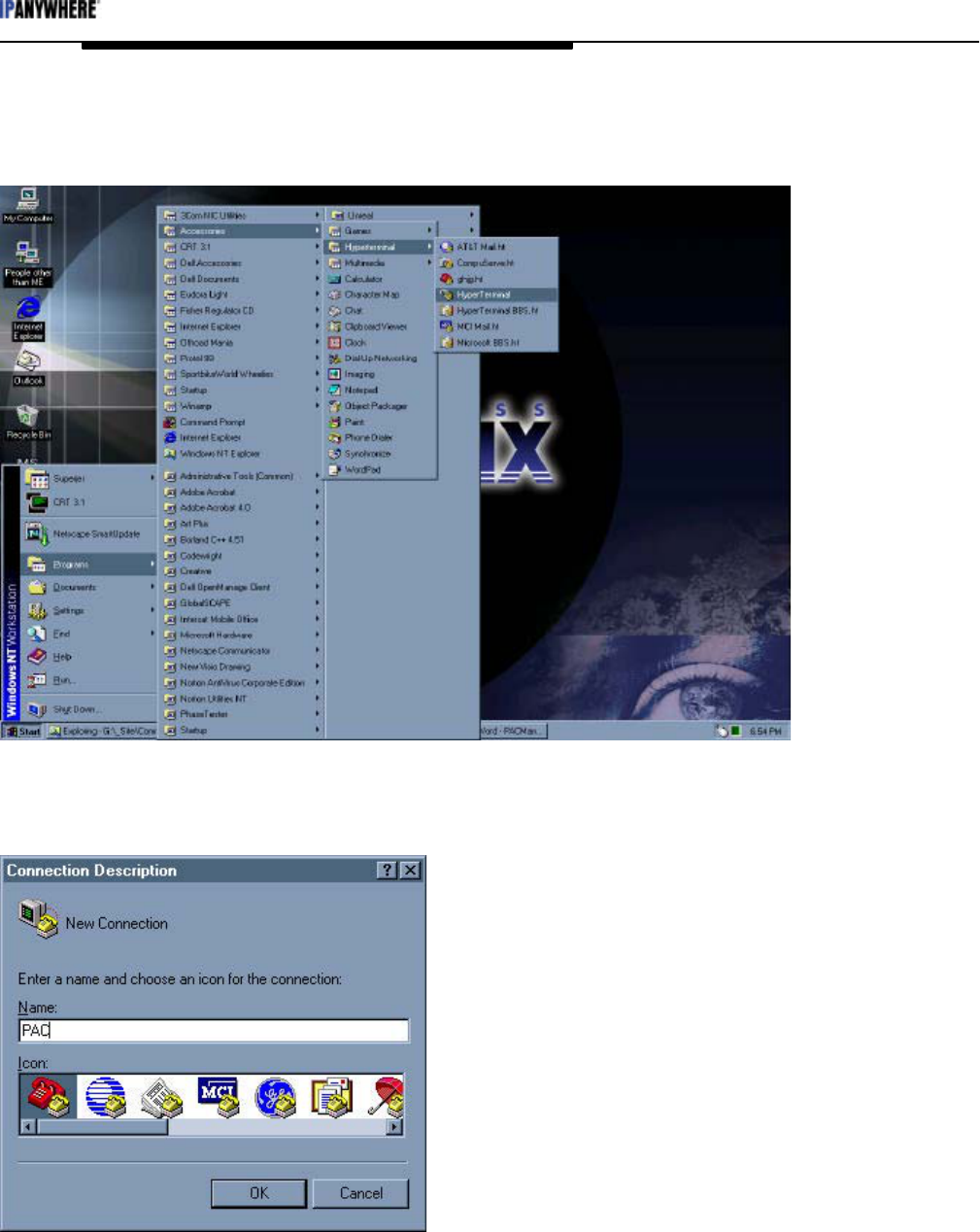
The following figures give step by step instructions to set up HyperTerminal. Some users
may prefer to use a different terminal program.
Figure 6: Starting HyperTerminal
Enter a name for the connection.
Figure 7: Naming the connection
PAC Configuration Manual
Wireless Matrix Corporation #102, 1530 - 27 Avenue NE Page 14 of 62
Document # xxx-xxx-xxx Calgary, AB, Canada T2E 7S6
2002.02.01 Ph. 403.250.3949 Fax 403.250.8163 www.wrx-ca.com
Select the COM port for the serial port connected to the TPAC.
Figure 8: Choose a COM port
Specify the communication settings, as shown below.
Figure 9: Specify port settings
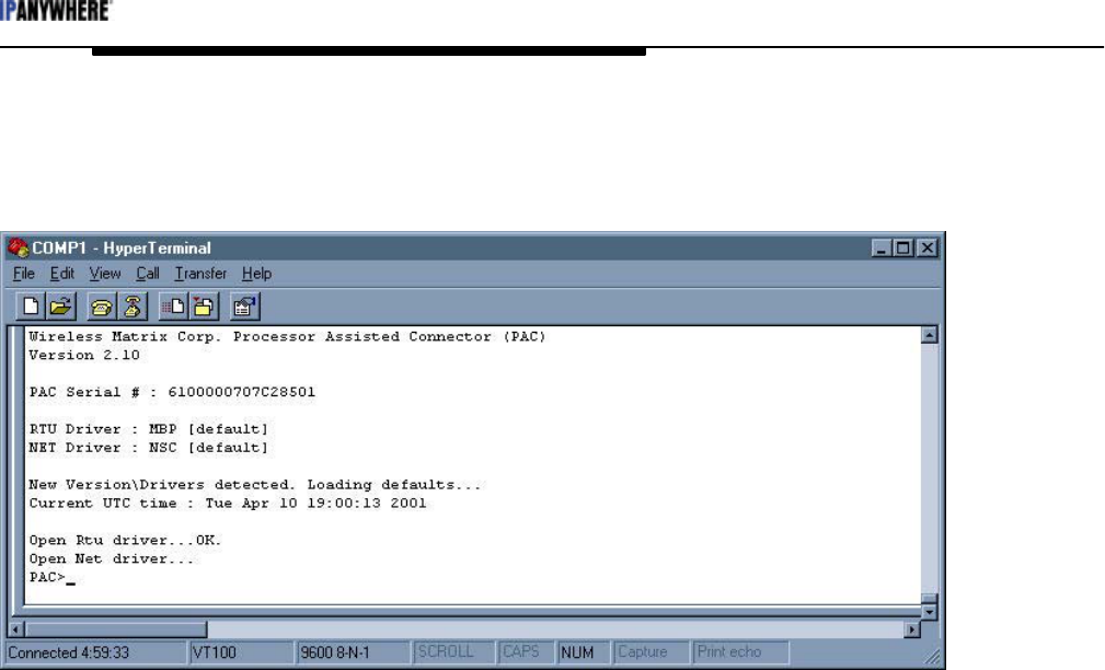
Click the OK button. Then click on the Call Disconnect and then Call Connect buttons.
(New port settings do not take effect until the session has been disconnected and
reconnected.)
Hit <enter> and the PAC> prompt should appear. .
The TPAC is ready for configuration.
PAC Configuration Manual
Wireless Matrix Corporation #102, 1530 - 27 Avenue NE Page 15 of 62
Document # xxx-xxx-xxx Calgary, AB, Canada T2E 7S6
2002.02.01 Ph. 403.250.3949 Fax 403.250.8163 www.wrx-ca.com
Save the settings so the session is available in the future. The session is saved using the
File|Save menu option. The settings for the session can be viewed or changed using the
File|Properties menu option.
Figure 7: PAC prompt
If the prompt PAC> does not appear on the screen, the TPAC may be in sleep mode. Try
cycling the power or shorting the WK LN terminal to the GND terminal to wake the TPAC.

PAC Configuration Manual
Wireless Matrix Corporation #102, 1530 - 27 Avenue NE Page 16 of 62
Document # xxx-xxx-xxx Calgary, AB, Canada T2E 7S6
2002.02.01 Ph. 403.250.3949 Fax 403.250.8163 www.wrx-ca.com
3.2 TPAC User Interface
This section assumes the programmer has the basic understanding of the TPAC functionality
and the end devices connected to the TPAC. The TPAC is configured using the PAC
command line interface. The PAC command line interface has a tree structure and uses
minimum truncation so only letters necessary to make the command unique need to be
entered. The manual shows the necessary characters in capital letters. The PAC command
line interface is not case sensitive. When the TPAC powers up, the terminal screen displays
the firmware version, electronic serial number and the network and RTU drivers that are
loaded.
3.2.1 General PAC Commands
The following list of general PAC commands:
HALT – Halt execution of the PAC. This is useful when configuring the PAC.
RUN – Start PAC execution.
SHow – Display the entire PAC configuration.
SHow PAC – Display the parameters that are applicable to the PAC application.
SHow RTU – Display the parameters that are applicable to the RTU or end-device.
SHow NET – Display the parameters that are applicable to the network device (Radio).
HElp – List all the commands and the format for each command.
WRite – Save the current configuration in non-volatile memory.
REBOOT – Restart the PAC as if power was first applied. The PAC will start with the
configuration stored in non-volatile memory. The PAC will start in RUN mode.
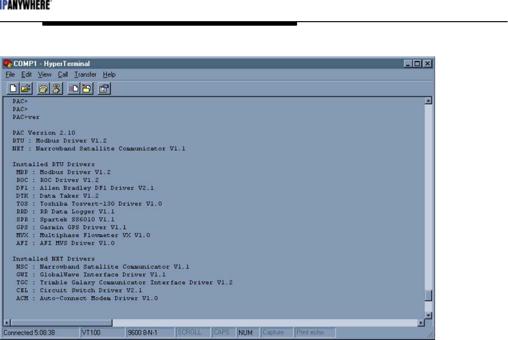
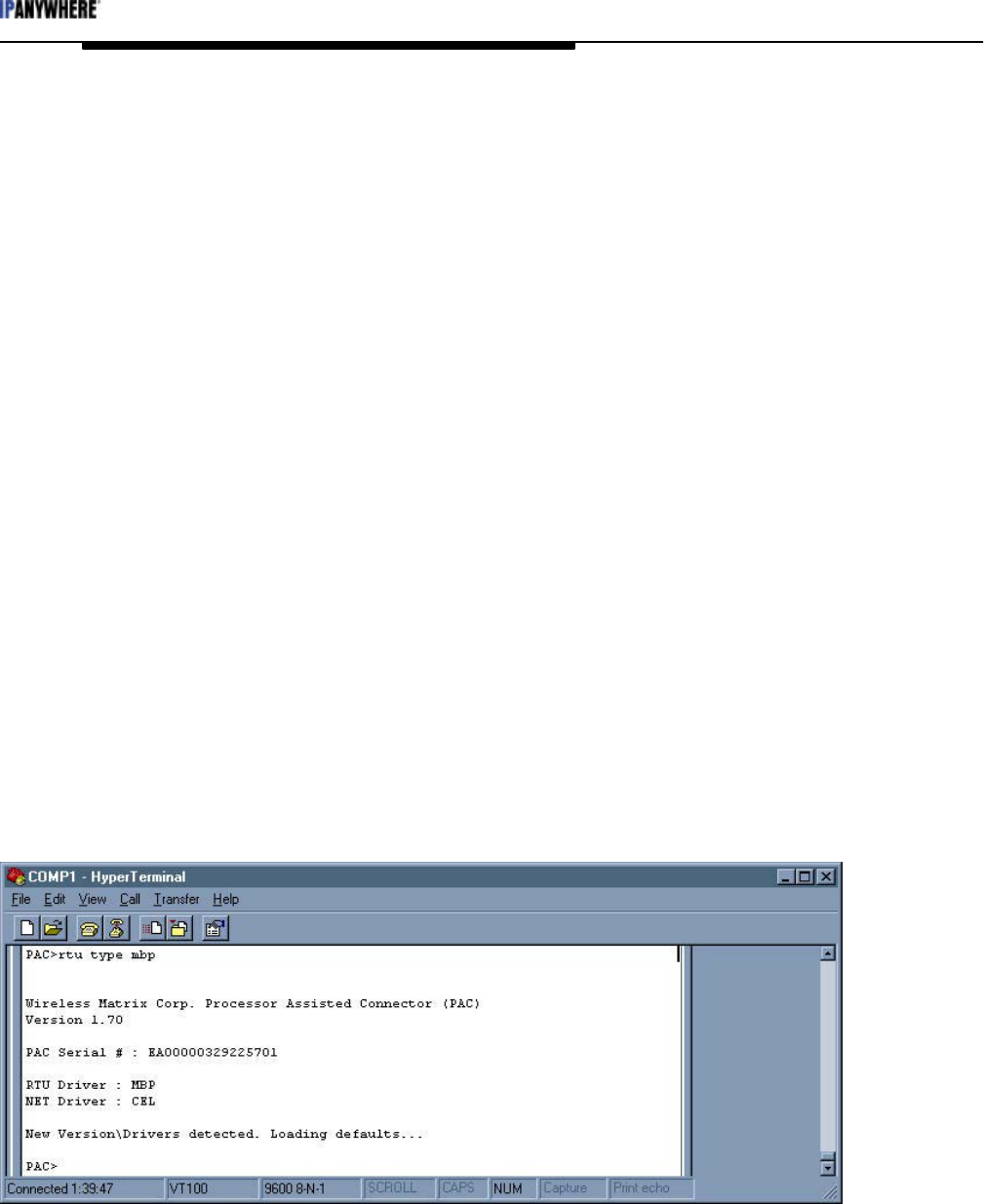
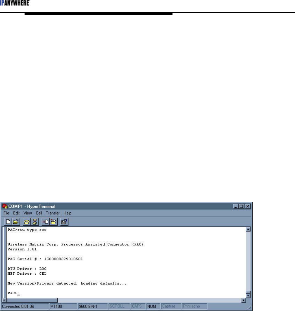
VERsion – Display the firmware version and the loaded and available drivers. See the
following screen capture.
PAC Configuration Manual
Wireless Matrix Corporation #102, 1530 - 27 Avenue NE Page 17 of 62
Document # xxx-xxx-xxx Calgary, AB, Canada T2E 7S6
2002.02.01 Ph. 403.250.3949 Fax 403.250.8163 www.wrx-ca.com
Figure 10: Display the version
3.2.2 Setting PAC Values
The “SHow” command displays all the PAC settings. The settings are displayed as a tree of
main settings with sub settings. To set a specific value, the complete path to the setting must
be given.
For example, to set the RTU’s baudrate, issue the command…
RTU COMM BAUD <baud rate>
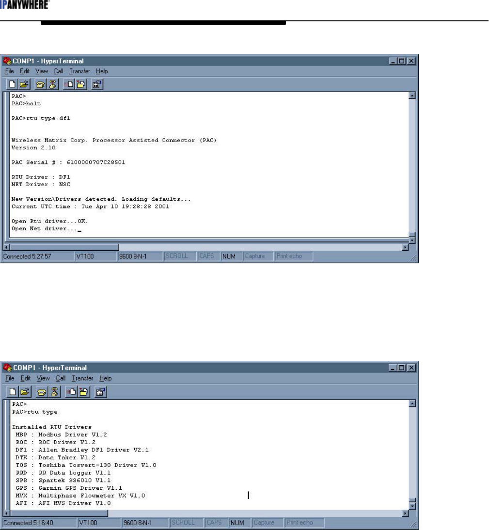
3.2.3 Loading Drivers
The default RTU driver in the PAC is Modbus. The network driver for a TPAC with a
DataTAC module is Radio Access Protocol (RAP). A new RTU driver can be specified if
necessary. This should be done before any other settings are changed. When a drivers is
changed, the PAC will reboot and set default values for the new driver. For example, type
RTU TYPE DF1 to load the DF1 driver. This will change the RTU driver to DF1, save the
RTU driver and cause the PAC to reboot and restore relevant values for the DF1 driver.
PAC Configuration Manual
Wireless Matrix Corporation #102, 1530 - 27 Avenue NE Page 18 of 62
Document # xxx-xxx-xxx Calgary, AB, Canada T2E 7S6
2002.02.01 Ph. 403.250.3949 Fax 403.250.8163 www.wrx-ca.com
Figure 11: Load new RTU drivers
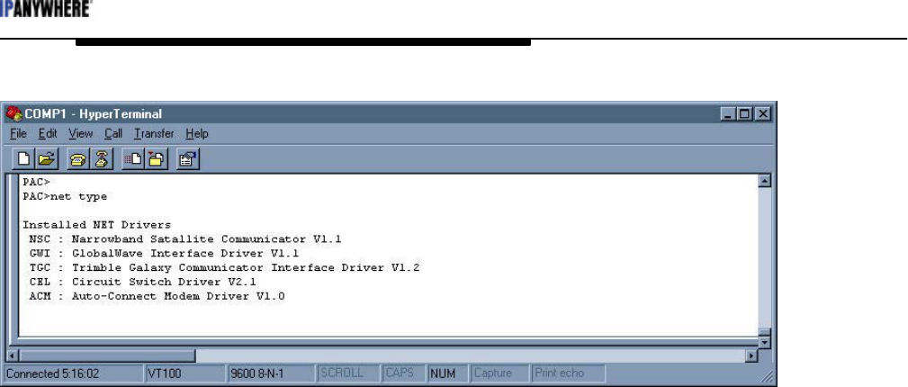
Type VER to list all drivers. Type RTU TYPE to list the RTU drivers. Type NET TYPE to
list the network drivers. The PAC must be Halted before changing a driver. See the
following figures for examples.
Figure 12: RTU Types
PAC Configuration Manual
Wireless Matrix Corporation #102, 1530 - 27 Avenue NE Page 19 of 62
Document # xxx-xxx-xxx Calgary, AB, Canada T2E 7S6
2002.02.01 Ph. 403.250.3949 Fax 403.250.8163 www.wrx-ca.com
Figure 13: Network Types
Ensure that the proper drivers are loaded before continuing with the configuration.
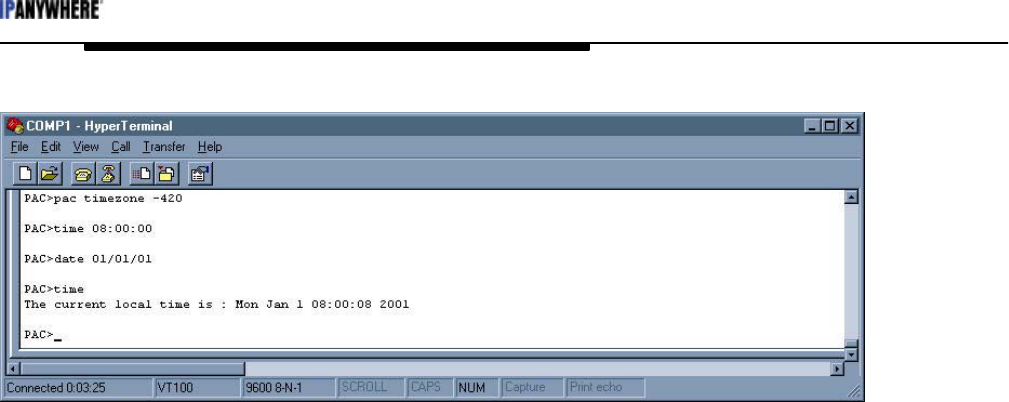
3.2.4 Displaying and Setting the System Time
Time is tracked in GMT in the PAC. The PAC can display or set time in the local time, if an
offset from GMT is defined. Define the time zone offset before setting the time.
Time values are set as follows:
TIme or DAte – Display the current local time or date.
PAC TIMEZone <+/- minutes> – The TIMEZONE setting is in the PAC submenu so PAC
must be entered before TIMEZone. Enter the time zone offset in minutes. For example, the
time in Alberta is GMT minus seven hours so enter –420. Disregard daylight savings time
when the time zone is offset is entered. For example, in Alberta the time zone offset is
always entered as –7 hours even though the local time is only –6 hours during daylight
savings time.
TIme <HH:MM:SS> – The command and format to set the time. The PAC time is set to
local time if a time zone offset is defined. Setting the correct time is important for scheduled
reports.
DAte <MM:DD:YY> – The command and format to set the date in the PAC. Note the
order.
PAC Configuration Manual
Wireless Matrix Corporation #102, 1530 - 27 Avenue NE Page 20 of 62
Document # xxx-xxx-xxx Calgary, AB, Canada T2E 7S6
2002.02.01 Ph. 403.250.3949 Fax 403.250.8163 www.wrx-ca.com
Figure 14: Setting the system time
3.2.5 PAC Application Commands
The default values in the PAC configuration are usually acceptable. The following list of
commands is used to configure the PAC global settings.
Note: The parameters inside the brackets < > must be entered. The symbol “|” is “or” so on |
off indicates “on” or “off” is entered.
PAC RPTBack <on | off> – Report-back causes the PAC to send an acknowledgement back
to the GDN that a message was received successfully. Recommended state of this flag is
always ON.
PAC RPTMode <0:Compact| 10:GDN 11:|PSTN> – This determines the size and format
of the message. GDN (10) is used for normal operation in the TPAC and most other network
drivers. Compact (0) is only used for the Vistar terminal to limit packet size. PSTN (11) is
used for dial-up applications. Type 11 uses the PAC serial number as an encrypted password
and identification. The serial number also used as an address when a group of PACs share a
network connection such as multiple PACs on one IP address.
PAC LOWpower <on | off> – The PAC can be set to enter a low power mode in between
poll and report tasks. The option is used to conserve power on a remote site.
PAC TAG <0…> – The tag is set to the external serial number on the PAC label.
PAC IPDelay <0…> – Inter-point delay is the number of seconds to wait between polling
successive I/O points.
PAC DEbug <on | off> – The PAC will show application-level messages. This is one of
several levels of message detail available via the PAC command line interface.
PAC AWAKE <…35…> – The minimum number of seconds that the PAC is awake when
low power is enabled.

PAC Configuration Manual
Wireless Matrix Corporation #102, 1530 - 27 Avenue NE Page 21 of 62
Document # xxx-xxx-xxx Calgary, AB, Canada T2E 7S6
2002.02.01 Ph. 403.250.3949 Fax 403.250.8163 www.wrx-ca.com
PAC ARChive <on | off> – This setting is for Wireless Matrix configuration only. The
default is ON and it should be left ON.
PAC POW <0…> – Pause on wake-up. This setting delays the PAC from polling for a set
amount of time in seconds. This is used to provide transmitters time to stabilize when using
the PAC on-board I/O. This setting is also used when the communication device needs a
delay to "key up" after receiving DTR.
WRite – Save the current settings in non-volatile memory so they are available the next time
the PAC powers up.
Version – Display the current PAC firmware version and list the drivers that are available.
Note that each driver has a separate version number.
RTU <open | close> – Open or close the RTU driver.
ZAP – This command will erase the PAC configuration and I/O point list from non-volatile
memory. The PAC will boot with a default configuration unless a WRITE command is
issued before the PAC is powered down.
ZAP cfg – This command only erases the configuration of the PAC.
ZAP gdn – This command only erases the I/O point database list in the PAC.
Poll <pid> – PAC will poll the specified poll-set <pid>.
REPort <pid> – PAC will send report for the specified poll-set <pid>.
DOWNLOAD – This command is used to upgrade the PAC firmware. Do not use this
command unless you have the tools to upgrade the PAC firmware. Cancel by command by
cycling power to the PAC prior the starting the code download.
3.3 I/O Point Database
The PAC maintains a list of all the I/O points it needs to access. Each point can have alarms
associated with it. See the sections on alarms. PAC version 2.1x and later can access up to
340 I/O points. I/O points are usually added remotely through the GDN but points can be
added locally. Each I/O point has a list of parameters associated with it. The parameters
define the context the PAC needs to access the I/O point correctly. Two parameters, poll-set
ID (PID) and index are common to all I/O points. The remaining parameters are specific to
the driver. Some I/O points are internal to the PAC.
The poll-set ID is a reference number used to group I/O points. Poll and report events are
based on the poll-set ID. For example, all I/O points with poll-set id 1 are a group and will
be polled and reported together. Valid poll-set ID numbers are 1-254 (255 is reserved for
internal points).

PAC Configuration Manual
Wireless Matrix Corporation #102, 1530 - 27 Avenue NE Page 22 of 62
Document # xxx-xxx-xxx Calgary, AB, Canada T2E 7S6
2002.02.01 Ph. 403.250.3949 Fax 403.250.8163 www.wrx-ca.com
The index is a unique number that identifies the I/O point within the PAC. If a new I/O point
is added with the same index as an existing I/O point, the new point will overwrite the
existing point. Valid index numbers are 1-127 and 256-1200 (128-255 are reserved for PAC
internal I/O points).
The following commands are used to create and modify the I/O list. The I/O list is set up
differently for each RTU Driver. See the RTU driver section for the appropriate setup. The
commands for configuring I/O points are:
GDN LIst <pid> – This command will list the I/O points in the poll-set. Valid values for
<pid> are 1-255. Type "GDN LIST 255" to display the internal I/O points. Type "GDN
LIST" without a number to list all the I/O points except PAC internal I/O points (PID 255).
GDN ADd <pid><index><address><f1><f2><f3><f4><type> – Use this command to add
or modify an I/O point. Specify a unique index to add a point. Specify the index of an
existing point to modify the point. Refer to the appropriate RTU driver section for a
definition of the <address>, <f1>, <f2>, <f3> and <f4> parameters. The <type> parameter
can be one of the following: 1=discrete 2=char 3=uchar 4=int 5=uint 6=long 7=ulong 8=float
GDN REad <index> – Read the current value of the specified I/O point.
GDN WRite <index> <value> – Write a new value to the specified I/O point.
GDN DElete <index> – Erase the specified I/O point from the PAC.
3.4 Alarms
An alarm is a threshold value specific to an I/O point. The alarm values are stored in the
PAC. If the PAC reads the value of an I/O point and determines the value has crossed the
threshold, the PAC will send an alarm-report. The alarm-report contains the values of all the
I/O points in the poll-set. The PAC sends an alarm report when the value crosses into the
alarm region and another report when the value crosses out of the alarm region. Alarms are
normally added remotely through IP Anywhere when a site is commissioned.
Each I/O point can have 4 alarm thresholds High-High, High, Low, Low-Low and a
hysterisis. Hysterisis changes the alarm threshold for an I/O point to cross out of the alarm
region. The threshold is modified by the value of the hysterisis. Hysterisis is used to prevent
excessive alarm reports from an I/O value that is close to the threshold and is bouncing back
and forth across the threshold.
Example: A high alarm is set to 10 and the hysterisis is set to 2. If the measured value rises to
11, an alarm will occur and an alarm report is sent. The I/O point will not return to normal
until the value drops below 8. If the value drops from 11 to 9 and then returns to 11, the I/O
point stays in alarm condition and an alarm report not sent.

PAC Configuration Manual
Wireless Matrix Corporation #102, 1530 - 27 Avenue NE Page 23 of 62
Document # xxx-xxx-xxx Calgary, AB, Canada T2E 7S6
2002.02.01 Ph. 403.250.3949 Fax 403.250.8163 www.wrx-ca.com
Figure 15: Alarm Hysterisis
“O” denotes a limit transition
The following command is used to enter an alarm.
GDN ALarm <index> <HH | *> <H | *> <L | *> <LL | *> <HYS | *> – This command
enters alarm thresholds for the specified I/O point. Enter * in place of a value if the alarm or
hysterisis not specified. HH denotes the high-high alarm threshold, H denotes the high alarm
threshold, L denotes the low alarm threshold, LL denotes the low-low alarm threshold and
HYS denotes hysterisis.
3.4.1 Deadband Alarms
A dead-band alarm monitors a single I/O point for a change that is greater then the specified
threshold. Dead-band alarms are not relevant when low-power is enabled.
Dead-band alarms can be added via the command line interface using the following format.
GDN ALARM DB <index> <Npoints> <DB Value> – The command sets a dead-band
alarm for the specified I/O point. <DB Value> is the dead-band or change threshold.
<Npoints> determines the mode of the dead band alarm as shown below:
Npoints = 0 – Dead-band from last reported value. An alarm report is sent when a
new I/O value differs from the last reported value by more then the dead-band.
Npoints = 1 – Dead-band from last sampled value. An alarm report is sent when a
new I/O value differs from the previous value by more then the dead-band.

PAC Configuration Manual
Wireless Matrix Corporation #102, 1530 - 27 Avenue NE Page 24 of 62
Document # xxx-xxx-xxx Calgary, AB, Canada T2E 7S6
2002.02.01 Ph. 403.250.3949 Fax 403.250.8163 www.wrx-ca.com
Npoints > 1 – Dead-band from average value. An alarm report is sent when a new
I/O value differs from the average of the previous <Npoints> values by more then the
dead-band.
Disable a dead-band alarm by setting the alarm dead-band value to zero.
3.5 Scheduling
Scheduling is one of the most important features of the PAC. Two important scheduling
concepts are start time and interval time.
Start Time - This is the date and time the PAC will start the event. This is usually set in the
past so the event will start immediately. It can be set in the future if necessary, but this is not
recommended.
Interval time - The interval determines how frequently the PAC will execute an event,
beginning from the start time.
Two types of events to schedule in the PAC are polls and reports.
A poll event causes the PAC to request data from an end-device. If low power is enabled the
PAC will sleep in between polls to conserve power. The poll interval depends on how time
critical it is to know of changes in the data being polled versus the available power on site.
A report event causes the PAC to poll for the latest values and send the values to IP
Anywhere.
The following commands are used to configure an event.
EVENT SET <index> <type> <pid> <start> <interval> – This command will create a new
event or modify of an existing event.
Index There are 16 available event records, 1 - 16 are valid
Type Available event types are
POLL - Read IO Pollset
REPORT - Read IO Pollset, and
STATUS - Request status from NET (communicator)
REBOOT - Restart application.
PID For POLL/REPORT events, a pollset id must be specified. For
STATUS/REBOOT events, no PID should be given.
Start The start time for the event. Long format:
MM/DD/YY HH:MM:SS
Where: MM = month (1-12); DD = day (1-31); YY = year (00-99); HH
= hour (00-23); MM = minute (00-59); SS=seconds (00-59)
Brief formats:

PAC Configuration Manual
Wireless Matrix Corporation #102, 1530 - 27 Avenue NE Page 25 of 62
Document # xxx-xxx-xxx Calgary, AB, Canada T2E 7S6
2002.02.01 Ph. 403.250.3949 Fax 403.250.8163 www.wrx-ca.com
HH:MM:SS – Default start date = 01/01/80
HH:MM – Default start date = 01/01/80; Default second = 00.
Interval Time between events. Long format:
DD HH:MM:SS
Where DD = days (00-99)
Brief format.
HH:MM:SS – Default days = 00
HH:MM – Default days = 00, Default seconds = 00.
EVENT DELETE <index> – This command disables an event.
EVENT LIST – This command displays all active events.
Note: Short forms can be used to modify existing events.
Event set <index> int DD HH:MM:SS
Event set <index> st MM/DD/YY HH:MM:SS
Event set <index> pid 1-254

PAC Configuration Manual
Wireless Matrix Corporation #102, 1530 - 27 Avenue NE Page 26 of 62
Document # xxx-xxx-xxx Calgary, AB, Canada T2E 7S6
2002.02.01 Ph. 403.250.3949 Fax 403.250.8163 www.wrx-ca.com
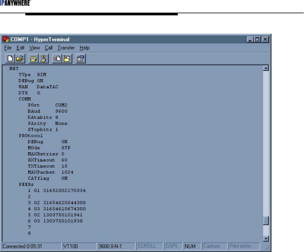
4 TPAC Network Drivers and Settings
The TPAC network driver is type “RIM”. Display the network settings by typing “SHOW
NET”. This section contains detailed information to configure the network driver.
NET
TYpe RIM – Type "NET TYPE" to list all the available drivers in the PAC. Only
the “RIM” network driver is relevant to the TPAC.
DEbug <on | off> – Turn on this level of debug to view network-level application
messages. The messages can help with troubleshooting.
WAN <DataTAC | Mobitex> – Specify the wireless network. The default is
DataTAC.
DTR <0 | 1> – Specify the active state of the DTR connection. The default is 0.
COMM
POrt <COM1 | COM2 | COM4> – COM1 must be used for the TPAC.
BAud <1200 | 2400 | 4800 | 9600 | 14400 | 19200 | 28800 | 38400>
DAtabits <7 | 8>
PArity <None | Even | Odd>
STopbits <1 | 2>
PROtocol – The network protocol settings are shown below.
DEbug <on | off> – Turn on this level of debug to view network protocol
level application messages.
MOde <STP | FAD | APL> – The mode defines the protocol that the network
driver will use to communicate. The TPAC uses mode STP.
MAXRetries <0> – The maximum number of messages sent to network
before aborting the attempt. The default is 0.
RXTimeout <sec> – Incoming packet fragment timeout. The number of
seconds the PAC will wait before discarding a broken or incomplete message.
The default is 60.
TXTimeout <sec> – Packet Acknowledgement timeout. The number of
seconds that the PAC will wait for a message acknowledgement from the
GDN before re-sending the message.
MAXPacketsize <bytes> – The maximum number of bytes that the network
can support in a single packet.
PEERs – This setting allows Direct Connect and Remote Console Programming.
This setting does not apply to the TPAC.
PAC Configuration Manual
Wireless Matrix Corporation #102, 1530 - 27 Avenue NE Page 27 of 62
Document # xxx-xxx-xxx Calgary, AB, Canada T2E 7S6
2002.02.01 Ph. 403.250.3949 Fax 403.250.8163 www.wrx-ca.com
Figure 16: Network settings display

PAC Configuration Manual
Wireless Matrix Corporation #102, 1530 - 27 Avenue NE Page 28 of 62
Document # xxx-xxx-xxx Calgary, AB, Canada T2E 7S6
2002.02.01 Ph. 403.250.3949 Fax 403.250.8163 www.wrx-ca.com
5 TPAC RTU Drivers and Settings
The RTU driver is one of the first parameters that should be set when configuring a TPAC.
Select the appropriate driver for the application.
The TPAC is capable of polling many different devices. Some of the most common TPAC
RTU drivers are Modbus (RTU, ASCII, Daniel, Modicon and Enron), ROC Protocol and
Allen Bradley DF1. New drivers are added frequently. The different drivers do not have all
the same configuration parameters. List the available drivers in the TPAC by typing "RTU
TYPE". This section contains detailed information to configure each driver.
A list of common commands and settings for all RTU drivers follows. “RTU” must be
entered at the start of all commands specific to the RTU section. The PAC must be halted to
load a new RTU driver.
RTU
TYpe <rtu> – Type "RTU TYPE" to list the available drivers.Change the RTU
driver by specifying the 3-letter acronym for the new driver. This will cause
the PAC to reboot and load default values for all RTU parameters. All
settings will be lost.
DEbug <on | off> – Turn on this level of debug to view RTU-level application
messages. The messages can help with troubleshooting.
COMM – The PAC communication settings must match the RTU settings.
POrt <COM1 | COM2 | COM4> – The RTU driver must use COM2
(RS232) or COM4 (RS485). COM1 is the network port for the TPAC.
BAud <1200 | 2400 | 4800 | 9600 | 14400 | 19200 | 28800 | 38400>
DAtabits <7 | 8>
PArity <None | Even | Odd>
STopbits <1 | 2>
PAC Configuration Manual
Wireless Matrix Corporation #102, 1530 - 27 Avenue NE Page 29 of 62
Document # xxx-xxx-xxx Calgary, AB, Canada T2E 7S6
2002.02.01 Ph. 403.250.3949 Fax 403.250.8163 www.wrx-ca.com
5.1 MODBUS Driver
RTU Driver : Modbus Driver V1.2
KeyCode : MBP
The Modbus protocol driver has the following settings:
RTU
TYpe MBP – Set the RTU driver to Modbus.
ASCii <off | on> – The default is “off”. Set ASCII “off” for binary (RTU) Modbus.
Set ASCII “on” for ASCII Modbus.
DEbug <off | on>
MAXRetries <2> – The default is 2.
RXTimeout <2> – The default is 2.
BYTEswap <off | on> – The default is “off”. It should be enabled for devices that
provide Intel byte order.
COMM
POrt <COM1 | COM2 | COM4> – The RTU driver must use COM2
(RS232) or COM4 (RS485). COM1 is the network port for the TPAC.
BAud <1200 | 2400 | 4800 | 9600 | 14400 | 19200 | 28800 | 38400>
DAtabits <7 | 8>
PArity <None | Even | Odd>
STopbits <1 | 2>
The Modbus driver is the default driver on a new TPAC. The Modbus driver in the TPAC
supports ASCII and RTU (binary) modes. This driver will be explained in more detail then
other drivers because it is the most common end device protocol. The following figure
shows the Modbus (MBP) driver being set.
Figure 17: Select the Modbus driver
After a new driver is specified, the TPAC reboots and the defaults for the new protocol are
loaded. Modify the default parameters to match the protocol of the end-device. The next
PAC Configuration Manual
Wireless Matrix Corporation #102, 1530 - 27 Avenue NE Page 30 of 62
Document # xxx-xxx-xxx Calgary, AB, Canada T2E 7S6
2002.02.01 Ph. 403.250.3949 Fax 403.250.8163 www.wrx-ca.com
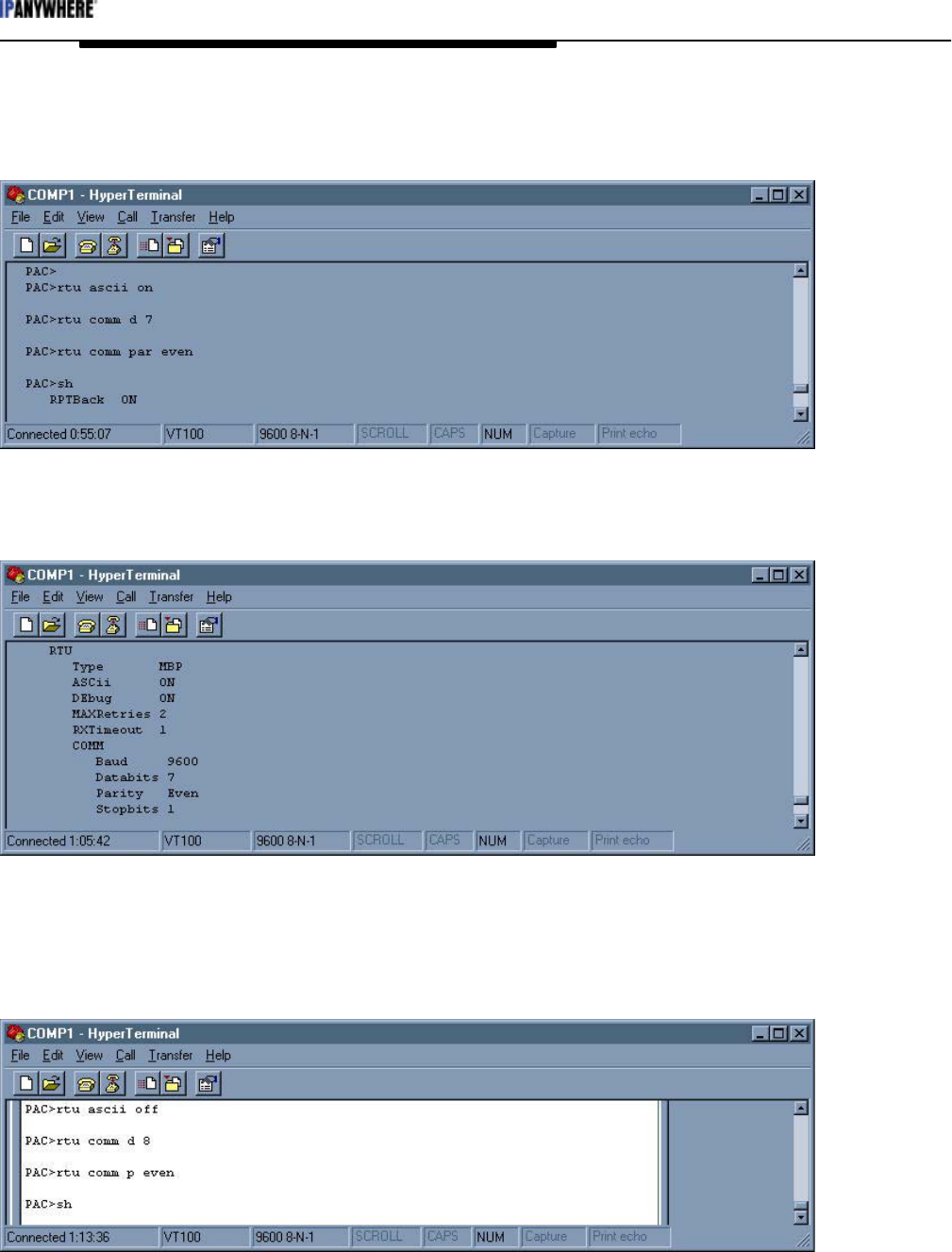
figure shows an example of a TPAC configuration for Modbus ASCII, 9600 baud, 7 data
bits, and even parity.
Figure 18: Configure TPAC for Modbus ASCII
Check the parameters by typing “SHow”.
Figure 19: Check Settings for Modbus ASCII
Verify the settings are correct and type “WRite” to save the settings to non-volatile memory.
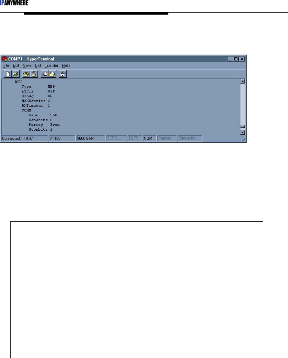
The next figure is an example of a TPAC configuration for Modbus RTU, 9600 baud, 8 data
bits, and even parity.
Figure 20: Configure TPAC for Modbus RTU
PAC Configuration Manual
Wireless Matrix Corporation #102, 1530 - 27 Avenue NE Page 31 of 62
Document # xxx-xxx-xxx Calgary, AB, Canada T2E 7S6
2002.02.01 Ph. 403.250.3949 Fax 403.250.8163 www.wrx-ca.com
Check the parameters by typing “SHow”.
Figure 21: Check Settings for Modbus RTU
Verify the settings are correct and type “WRite” to save the settings to non-volatile memory.
MBP Driver I/O Configuration
I/O points for Modbus are determined by the Modbus register number and type. Add or
modify and I/O point to the TPAC with the following command and the parameters.
GDN ADd <pid> <index> <address> <f1> <f2> <f3> <f4> <type>
TPAC I/O point definition for the Modbus driver.
pid Choose the pollset that that the point is to be added to. (1-254)
index Unique index number of the I/O point (1-127, 256-1200) (128-255 are reserved
for PAC internal I/O points). If the I/O point index exists, the new settings
will over-write the old settings.
address The Modbus slave address (1-255) of the end-device
f1 The Modbus register series (Daniel: 700, 1000, 5000, 7000 | Modicon: 0,
10000, 30000, 40000)
f2 The register offset from the series in f1. For example, if the Modbus register is
40003, enter 40000 in f1 and 3 in f2.
f3 Number of registers in a block for a BLOB;
Or the archive record number, found in 3004, for Daniel archives;
Or enter 0.
f4 The maximum number of registers that can be polled in one block for a BLOB;
Or bit number (mask a single bit) within integer register;
Or the archive record number for Daniel;
Or enter 0.
type 1=discrete; 2=char; 3=uchar; 4=int; 5=uint; 6=long; 7=ulong; 8=float; 9 =blob;
PAC Configuration Manual
Wireless Matrix Corporation #102, 1530 - 27 Avenue NE Page 32 of 62
Document # xxx-xxx-xxx Calgary, AB, Canada T2E 7S6
2002.02.01 Ph. 403.250.3949 Fax 403.250.8163 www.wrx-ca.com
5.2 ROC Protocol Driver
RTU Driver : ROC Driver V1.2
KeyCode : ROC
The ROC protocol driver has the following settings:
RTU
TYpe ROC – Set the RTU driver to ROC protocol.
DEbug <off | on>
MAXRetries <3> – The default is 3.
RXTimeout <2> – The default is 2.
Unit <240> – This is the unit number of the PAC. The default is 240.
Group <240> – This is the group number of the PAC. The default is 240.
COMM
POrt <COM1 | COM2 | COM4> – The RTU driver must use COM2
(RS232) or COM4 (RS485). COM1 is the network port for the TPAC.
BAud <1200 | 2400 | 4800 | 9600 | 14400 | 19200 | 28800 | 38400>
DAtabits <7 | 8>
PArity <None | Even | Odd>
STopbits <1 | 2>
Figure 22: Select the ROC Driver
After a new driver is specified, the TPAC reboots and the defaults for the new protocol are
loaded. Modify the default parameters to match the protocol of the end-device. Two unique
parameters for the ROC driver are “Unit” and “Group”. These define the address the TPAC
uses to identify itself. The ROC response to a poll from the TPAC is addressed to the TPAC
unit address and group number. The unit address and group number both default to 240,
which works for most applications.
PAC Configuration Manual
Wireless Matrix Corporation #102, 1530 - 27 Avenue NE Page 33 of 62
Document # xxx-xxx-xxx Calgary, AB, Canada T2E 7S6
2002.02.01 Ph. 403.250.3949 Fax 403.250.8163 www.wrx-ca.com
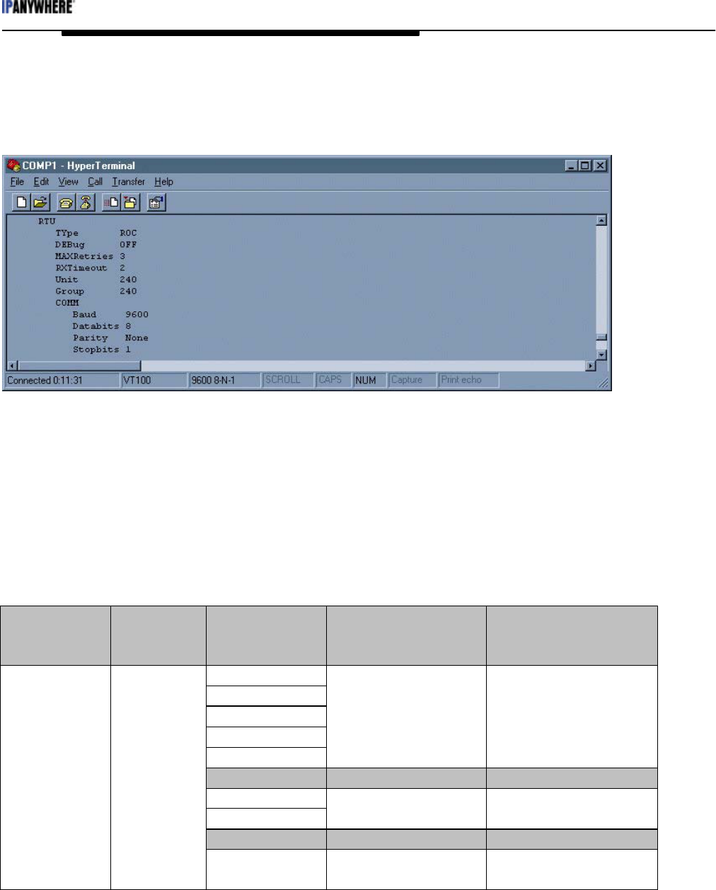
Most ROC devices have default communication settings of 9600 bits per second, 8 data bits,
no parity and 1 stop bit. If the communication is not working, use ROCLINK of GV101 to
verify the ROC settings. The next figure shows a sample ROC configuration.
Figure 23: ROC Configuration
ROC Driver I/O Configuration
Add or modify and I/O point to the TPAC with the following command and the parameters.
GDN ADd <pid> <index> <address> <f1> <f2> <f3> <f4> <type>
The following table describes the parameters that are necessary to configure a ROC I/O
point. A ROC protocol manual may be required to determine the parameter numbers and
point types.
ROC I/O Point configuration
Address F1 F2 F3 F4
(ROC address) (ROC group
number)
(Point type)
1-DI
2-DO
3-AI
4-AO
5-PI
Location 0-68 Parameter #
6-Pid PID # 0-3 Parameter #
7-AGA config.
10-AGA flow
Flow Run #0-XX Parameter #
17-Soft points Softpoint # 0-31 Data #
Address Group
256-History History point # 0-89 # of days before
yesterday (yesterday=0)
Other point types can be used for various user programs.

PAC Configuration Manual
Wireless Matrix Corporation #102, 1530 - 27 Avenue NE Page 34 of 62
Document # xxx-xxx-xxx Calgary, AB, Canada T2E 7S6
2002.02.01 Ph. 403.250.3949 Fax 403.250.8163 www.wrx-ca.com
The following table correlates ROC data types to PAC data types.
PAC - ROC data type comparison
PAC data types ROC Data Type
1 – Discrete UC
2 – Char SC
3 – Unsigned char UC
4 – Integer SI
5 – Unsigned integer UI
6 – LONG SL
7 – Unsigned long UL
8 – Float FL
Not supported AC
Not supported BN
Not supported TLP

PAC Configuration Manual
Wireless Matrix Corporation #102, 1530 - 27 Avenue NE Page 35 of 62
Document # xxx-xxx-xxx Calgary, AB, Canada T2E 7S6
2002.02.01 Ph. 403.250.3949 Fax 403.250.8163 www.wrx-ca.com
5.3 Allen Bradley DF1 Driver
RTU Driver : Allen Bradley DF1 Driver V2.1
KeyCode :DF1
This driver will interface to a PLC that supports the Allen Bradley DF1 Protocol. The PAC
implements a subset of the commands transported via DF1 so support is restricted to PLCs
which use the “Protected Typed Logical Read/Write” commands.
The list of PLCs, tested and verified, follows:
- SLC 500 Series
- Micrologix 1500
The DF1 protocol driver has the following settings:
RTU
TYpe DF1 – Set the RTU driver to DF1 protocol.
DEbug <off | on>
ADDress <1> – The master address. Default is 1.
DUPlex <full | half> – The default is full duplex mode.
CHKsum <CRC | BCC> – The method of error checking. The default is CRC.
MAXRetries <2> – The default is 2.
RXTimeout <1> – The default is 1.
COMM
POrt <COM1 | COM2 | COM4> – The RTU driver must use COM2
(RS232) or COM4 (RS485). COM1 is the network port for the TPAC.
BAud <1200 | 2400 | 4800 | 9600 | 14400 | 19200 | 28800 | 38400>
DAtabits <7 | 8>
PArity <None | Even | Odd>
STopbits <1 | 2>
DF1 Driver I/O Configuration
IO Point Configuration:
The DF1 protocol uses a single byte (0-255) to address a particular device on a DF1 network.
The DF1 protocol has two modes, full duplex and half duplex. The mode depends on the
PLC network configuration. In half duplex mode, many PLCs may be present on the
network and each must be properly addressed to elicit the correct response. In full duplex
mode, only one PLC is connected and the address is irrelevant. However, when the address
does not match the PLC station number, there are occasional pauses in the response from the
PLC. Wireless Matrix recommends that the address always match the PLC station address.
I/O Addressing:
Almost all data within the PLC is addressable. The DF1 driver implements a standard
address scheme to access all data. The scheme is based upon the specifications for the
SLC500 series and Micrologix 1000 series. The following is the address format.

PAC Configuration Manual
Wireless Matrix Corporation #102, 1530 - 27 Avenue NE Page 36 of 62
Document # xxx-xxx-xxx Calgary, AB, Canada T2E 7S6
2002.02.01 Ph. 403.250.3949 Fax 403.250.8163 www.wrx-ca.com
TN:E.S/B
Component Description
T File Type
N File number
E Element number
S Sub-element number
B Bit number
In all Allan Bradley references, a letter or letters specify the file type. The following is a list
of those representations
File Type Description F1
S Status file 132
B Bit file 133
T Timer file 134
C Counter file 135
R Control file 136
N Integer file 137
F Floating point file 138
O Output file 139
I Input file 140
St String file 141
A ASCII file 142
Note: Some file types do not support all address components. Further, some components
may be omitted.
To translate from the Allen Bradley addressing scheme to the one used by the PAC, use the
format below:
GDN ADd <pid> <index> <address> <f1> <f2> <f3> <f4> <type>
Field Description
Address PLC (Station) Address
F1 Bit Number *& File Type
F2 File Number
F3 Element Number
F4 Sub-element Number
Type (element dependant)
*Note: If a bit number is not desired disregard the bit number in F1.Some addressing requires
a specific bit address. This is accomplished by utilizing the following format for the F1 field.
YYXXX : YY - Bit number
: XXX - File type

PAC Configuration Manual
Wireless Matrix Corporation #102, 1530 - 27 Avenue NE Page 37 of 62
Document # xxx-xxx-xxx Calgary, AB, Canada T2E 7S6
2002.02.01 Ph. 403.250.3949 Fax 403.250.8163 www.wrx-ca.com
Example:
DF1 AddressF1 F2F3F4Type
F8:4 138840Float
N7:3 137730Int
N7:3/4 04137 730Disc

PAC Configuration Manual
Wireless Matrix Corporation #102, 1530 - 27 Avenue NE Page 38 of 62
Document # xxx-xxx-xxx Calgary, AB, Canada T2E 7S6
2002.02.01 Ph. 403.250.3949 Fax 403.250.8163 www.wrx-ca.com
5.4 DataTaker Driver
RTU Driver : Data Taker V1.2
KeyCode : DTK
RTU
TYpe DTK – Set the RTU driver to DataTaker.
DEbug <off | on>
MAXRetries <2> – The default is 2.
RXTimeout <1> – The default is 1.
COMM
POrt <COM1 | COM2 | COM4> – The RTU driver must use COM2
(RS232) or COM4 (RS485). COM1 is the network port for the TPAC.
BAud <1200 | 2400 | 4800 | 9600 | 14400 | 19200 | 28800 | 38400>
DAtabits <7 | 8>
PArity <None | Even | Odd>
STopbits <1 | 2>
DTK Driver I/O Configuration
To translate add or modify I/O points for the DataTaker use the format:
GDN ADd <pid> <index> <address> <f1> <f2> <f3> <f4> <type>
GDN IO Point Definition for DataTaker DT800
IO Point Definition Usage
Address Channel Address
F1 Channel Type
F2 Channel Modifier #1
F3 Channel Modifier #2
F4 Channel Modifier #3
Type See below
IO Point types
- Analog input/output: Float
- Digital input/output:
- State I/O: Discrete
- Nibble/Byte I/O: Unsigned Char
- Word: Unsigned Integer
- Counter: Unsigned Integer
- Miscellaneous
- Channel Variable: Float
- System Variable: Float
- System Time: Unsigned Long

PAC Configuration Manual
Wireless Matrix Corporation #102, 1530 - 27 Avenue NE Page 39 of 62
Document # xxx-xxx-xxx Calgary, AB, Canada T2E 7S6
2002.02.01 Ph. 403.250.3949 Fax 403.250.8163 www.wrx-ca.com
Channel Types
ANALOG INPUTS:
Channel Modifiers
Type Measurement Description Command F2 F3 F4
0 Voltage no zero correction V - - Note 1
1 Voltage zero correction VNC - - Note 1
2 Current w/ external shunt I - - Note 1
3 Current 4-20mA current loop L - - Note 1
4 Resistance by 2,3,or 4 wire
method
R--Note 1
5 Conductivity by 2,3,or 4 wire
method
CO - - Note 1
6 Bridge 4-wire, quarter, half,
full
BGI - - Note 1
7 Radiometric 4&6 wire bridges BGV - - Note 1
8 Temperature Thermocouple T[c] Note
2a
-Note 1
9 Temperature Platinum RTD PT[n] Note
2b
-Note 1
10 Temperature Nickel RTD NI - - Note 1
11 Temperature Copper RTD CU - - Note 1
12 Temperature YS Series YS[n] Note
2b
-Note 1
13 Temperature AD Series AD[n] Note
2b
-Note 1
14 Temperature LM Series LM[n] Note
2b
-Note 1
15 Temperature TMP Series TMP[n] Note
2b
-Note 1
16 Temperature Diode Type DIODE - - Note 1
Note 1: F4 selects the channel usage
0 : Basic connection i.e.: 1V
1 : Positive terminal connection i.e.: 1+V
2 : Negative terminal connection i.e.: 1-V
3 : Default excitation applied i.e.: 1*V
4 : Return common terminal i.e.: 1#V
Note 2: F2 selects temperature sensor sub-type
2a : Selects Thermocouple type {1=A, 2=B, 3=C, 4=D,…}
2b : Selects sensor sub-type number {Addr=5, F1=12, F2=16 } = “5YS16”

PAC Configuration Manual
Wireless Matrix Corporation #102, 1530 - 27 Avenue NE Page 40 of 62
Document # xxx-xxx-xxx Calgary, AB, Canada T2E 7S6
2002.02.01 Ph. 403.250.3949 Fax 403.250.8163 www.wrx-ca.com
ANALOG OUTPUTS :
Channel Modifiers
Type Measurement Description Command F2 F3 F4
32 Voltage Voltage VO - - Note 3
Note 3: F4 selects the channel variable to store the output value into. Without this, the analog
output voltage cannot be read back. i.e. (Addr = 7, F1=32, F4=200} = “ 7VO(=200CV) = x”
DIGITAL INPUTS:
Channel Modifiers
Type Measurement Description Command F2 F3 F4
64 State 1 -Bit Input DS - - -
65 Nibble 4 -Bit Input DN - - -
66 Byte 8 -Bit Input DB - - -
67 Word 16 -Bit Input DW - - -
68 Counter 16 -Bit Up Counter C - - -
DIGITAL OUTPUTS :
Channel Modifiers
Type Measurement Description Command F2 F3 F4
96 State 1 -Bit Output DSO - - -
97 Nibble 4 -Bit Output DNO - - -
98 Byte 8 -Bit Output DBO - - -
MISCELLANEOUS:
Channel Modifiers
Type Measurement Description Command F2 F3 F4
255 Channel
Variable
Internal register CV - - -
254 System
Variable
Internal Maintenance SV - - -
253 System Timer Internal Timers ST - - -

PAC Configuration Manual
Wireless Matrix Corporation #102, 1530 - 27 Avenue NE Page 41 of 62
Document # xxx-xxx-xxx Calgary, AB, Canada T2E 7S6
2002.02.01 Ph. 403.250.3949 Fax 403.250.8163 www.wrx-ca.com
5.5 Toshiba Tosvert-130 Driver
RTU Driver : Toshiba Tosvert-130 Driver V1.0
KeyCode : TOS
This driver controls the Toshiba Tosvert-130 Transistor inverter. While there are various
models in the Tosvert-130 product line, the driver was designed for the G3 series. Other
models may be supported, but have not been tested.
RTU
TYpe TOS – Set the RTU driver to the Toshiba Tosvert-130 Transistor inverter.
DEbug <off | on>
CHKsum <off | on> – The default is on.
MAXRetries <2> – The default is 2.
RXTimeout <2> – The default is 1.
COMM
POrt <COM1 | COM2 | COM4> – The RTU driver must use COM2
(RS232) or COM4 (RS485). COM1 is the network port for the TPAC.
BAud <1200 | 2400 | 4800 | 9600 | 14400 | 19200 | 28800 | 38400>
DAtabits <7 | 8>
PArity <None | Even | Odd>
STopbits <1 | 2>
TOS Driver I/O Configuration
GDN ADd <pid> <index> <address> <f1> <f2> <f3> <f4> <type>
IO Point Configuration
Address : Inverter Number (INVNO)
F1 : Bank (0…4) Bank 0 : RAM
Bank 1 : EEPROM
Bank 2 : Internal ROM
Bank 3 : External ROM
Bank 4 : Option Bus
F2 : Address (0…0xFFFF) See Manual
F3 : Mask (0…0xFFFF) A mask value of 0 will be
interpreted as “NO MASK”.
Type : (See below)
Supported Point Types :
Discrete: Read / Write a single bit from bank memory F3 (Mask) is interpreted
as the bit number (F3=4 gives mask = 00010000)
Char, U_Char:Read / Write a single character from bank memory. As the Tosvert’s
memory is built around 2-byte data. It is recommended that Integer
data be used.

PAC Configuration Manual
Wireless Matrix Corporation #102, 1530 - 27 Avenue NE Page 42 of 62
Document # xxx-xxx-xxx Calgary, AB, Canada T2E 7S6
2002.02.01 Ph. 403.250.3949 Fax 403.250.8163 www.wrx-ca.com
Int, U_Int: Read / Write a 2-byte data location
Other formats:
Long, U_Long: Supported, but data is truncated to 2-bytes
Float : Supported. but data is converted from a 2-byte integer.
Mask usage:
Other than discrete point types, which return a single bit value 0 or 1, other point type
may also use the mask setting. In its simplest use, the mask can be used to limit data
written to the memory location. (Mask = 0x00FF will limit data to the range 0…255)
The mask may also be used to isolate bits in a word, so that other data within the
word is not corrupted.(Mask = 0x00C0 will only read / write bits 7 and 6)

PAC Configuration Manual
Wireless Matrix Corporation #102, 1530 - 27 Avenue NE Page 43 of 62
Document # xxx-xxx-xxx Calgary, AB, Canada T2E 7S6
2002.02.01 Ph. 403.250.3949 Fax 403.250.8163 www.wrx-ca.com
5.6 Spartek SS6010 Driver
RTU Driver : Spartek Systems V1.2
KeyCode : SPR
This driver will interface to the Spartek Systems SS6010 and 6010A down-hole recorder as
laid out in a document supplied by Spartek.
Driver Configuration (with default values):
RTU
TYpe SPR – Set the RTU driver to the Spartek Systems SS6010 and 6010A.
DEbug <off | on>
MAXRetries <2> – The default is 2.
RXTimeout <2> – The default is 2.
COMM
POrt < COM2> – The RTU driver must use COM2 (RS232).
BAud <9600>
DAtabits <8>
PArity <None>
STopbits <1>
SPR Driver I/O Configuration
GDN ADd <pid> <index> <address> <f1> <f2> <f3> <f4> <type>
IO Point Configuration
Address
:
not used.
F1 : Point Index - See table
below
F2 : not used
F3 : not used
F4 : not used
Type : See table below

PAC Configuration Manual
Wireless Matrix Corporation #102, 1530 - 27 Avenue NE Page 44 of 62
Document # xxx-xxx-xxx Calgary, AB, Canada T2E 7S6
2002.02.01 Ph. 403.250.3949 Fax 403.250.8163 www.wrx-ca.com
SS6010
F1 Point Description Point Type
0 Serial Number Unsigned Long
1 Elapsed time in secs Unsigned Long
2 Pressure Float
3 Temperature Float
4 Tool Configuration Unsigned Long
5 Raw pressure Unsigned Long
6 Raw temperature Unsigned Long
7 Tool Status Unsigned Long
SS6010a
F1 Point Description Point Type
0 Serial # Unsigned Long
1 Time Unsigned Long
2 Date Unsigned Long
3 Rawdata1 Unsigned Long
4 Rawdata2 Unsigned Long
5 Rawdata3 Unsigned Long
6 Rawdata4 Unsigned Long
7 Computed Pressure 1 Float
8 Computed
Temperature 1
Float
9 Computed Pressure 2 Float
10 Computed
Temperature 2
Float
11 Computed Pressure 3 Float
12 Computed
Temperature 3
Float
13 Configuration Unsigned Long
14 Status Unsigned Long

PAC Configuration Manual
Wireless Matrix Corporation #102, 1530 - 27 Avenue NE Page 45 of 62
Document # xxx-xxx-xxx Calgary, AB, Canada T2E 7S6
2002.02.01 Ph. 403.250.3949 Fax 403.250.8163 www.wrx-ca.com
5.7 Garmin GPS Driver
RTU Driver : Garmin GPS 25/35 Driver V2.0
KeyCode : GPS
The Garmin GPS driver uses the "Phase Output Data Binary Format" for its communications
with the RTU. As the binary format messages are transmitted on TXD2/RXD2, the cables
must be connected as follows
PAC GPS
RS232-RX Pin
2
TXD2
(Purple)
RS232-TX Pin
3
RXD2
(Green)
Vdc Vin (Red)
GND GND (Black)
RTU
TYpe SPR – Set the RTU driver to the Spartek Systems SS6010 and 6010A.
DEbug <off | on>
RXTimeout <5> – The default is 5.
COMM
POrt < COM2> – The RTU driver must use COM2 (RS232).
BAud <4800>
DAtabits <8>
PArity <None>
STopbits <1>
Note: These phase output data records can be disabled (via the $PGRMC1command).
Ensure the command "$PGRMC1,1,2<CR><LF>" is issued on the command port, prior to
commissioning. This will ensure these reports are generated at regular intervals.
GPS Driver I/O Configuration
GDN ADd <pid> <index> <address> <f1> <f2> <f3> <f4> <type>
IO Point definitions
Address : not used.
F1 : 40 This corresponds to (0x28) = Position record id
F2 : Point Index - See table below
F3 : not used
F4 : not used
Type : See table below

PAC Configuration Manual
Wireless Matrix Corporation #102, 1530 - 27 Avenue NE Page 46 of 62
Document # xxx-xxx-xxx Calgary, AB, Canada T2E 7S6
2002.02.01 Ph. 403.250.3949 Fax 403.250.8163 www.wrx-ca.com
F1 F2 Type
40 0 UInt GPS Fix (0=Invalid, 1=Invalid, 2=2D, 3=3D, ...) (see
appendix C)
40 1 FL GPS Latitude (deg) (+ == North, - == South)
40 2 FL GPS Longitude (deg) (+ == East, - == West)
40 3 FL GPS Altitude (mt)
40 4 FL Velocity : Latitude (mt/sec)
40 5 FL Velocity Longitude (mt/sec)
40 6 FL Velocity : Altitude (mt/sec)

PAC Configuration Manual
Wireless Matrix Corporation #102, 1530 - 27 Avenue NE Page 47 of 62
Document # xxx-xxx-xxx Calgary, AB, Canada T2E 7S6
2002.02.01 Ph. 403.250.3949 Fax 403.250.8163 www.wrx-ca.com
5.8 Delimited ASCII Driver
RTU Driver : Delimited ASCII Driver V1.0
KeyCode : DAD
The DAD driver is designed to receive an ASCII delimited string. The driver does not send
queries to the end device. The driver is designed to receive data only.
The Driver can be set up to accept all type of delimitation. Commas and spaces are usually
the most common. Also the number of expected values can be entered to filter invalid data.
Driver Configuration (with default values):
RTU
TYpe DAD – Set the RTU driver to the delimited ASCII.
DEbug <off | on>
RXTimeout <10> – The default is 10. This timeout must be set longer than the
interval that the device sends the data.
DELimiter <32> – This number represents the decimal equivalent of an ASCII
character (44=, (comma) and 32= (space))
NVALues <0> – The number of expected values can be entered to filter invalid data.
If the number is not known the it can be left as 0.
COMM
POrt <COM1 | COM2 | COM4> – The RTU driver must use COM2
(RS232) or COM4 (RS485). COM1 is the network port for the TPAC.
BAud <1200 | 2400 | 4800 | 9600 | 14400 | 19200 | 28800 | 38400>
DAtabits <7 | 8>
PArity <None | Even | Odd>
STopbits <1 | 2>
DAD Driver I/O Configuration
GDN ADd <pid> <index> <address> <f1> <f2> <f3> <f4> <type>
IO Point Configuration
Address : not used.
F1 : Point Index -= the place
that the desired value holds
in the expected string of
values
F2 : not used
F3 : not used
F4 : not used
Type : Float

PAC Configuration Manual
Wireless Matrix Corporation #102, 1530 - 27 Avenue NE Page 48 of 62
Document # xxx-xxx-xxx Calgary, AB, Canada T2E 7S6
2002.02.01 Ph. 403.250.3949 Fax 403.250.8163 www.wrx-ca.com
5.9 AFI MVS Driver
RTU Driver : AFI MVS Driver V1.1
KeyCode : AFI
The AFI Driver is functionally equivalent to Modbus (See Modbus). The difference lies in
the auto-time synchronization feature. Two items must be properly configured for the AFI
auto-time synchronization feature to work properly.
To enable the feature, a point must be added as follows.
PID INDEX ADDRESS F1 F2 F3 F4 TYPE
? ? ? 40000 502 0 0 (UINT)
The point must also be included in a pollset, which is polled on a regular basis. It is
suggested to use poll-set 2 and schedule the record to be read hourly. If ever this register
returns with either bit0, or bit1 set (=1), a time synchronization is required and the driver will
write the correct time to the AFI's date/time registers automatically.
In order for the correct LOCAL time to be written to the AFI meter, the correct TIMEZone
must be configured in the PAC.
Driver configuration is the same as Modbus.
RTU
TYpe AFI – Set the RTU driver to AFI.

PAC Configuration Manual
Wireless Matrix Corporation #102, 1530 - 27 Avenue NE Page 49 of 62
Document # xxx-xxx-xxx Calgary, AB, Canada T2E 7S6
2002.02.01 Ph. 403.250.3949 Fax 403.250.8163 www.wrx-ca.com
5.10 Pressure Trax ILI Technologies Driver
RTU Driver : ILI Technologies : PressureTrax V1.1
KeyCode : PRT
Driver configuration:
RTU
TYpe PRT – Set the RTU driver to the PressureTrax.
DEbug <off | on>
RXTimeout <8> – The default is 5.
MAXRetries <2> – The default is 2.
COMM
POrt < COM2> – The RTU driver must use COM2 (RS232).
BAud <4800>
DAtabits <8>
PArity <None>
STopbits <1>
PRT Driver I/O Configuration
GDN ADd <pid> <index> <address> <f1> <f2> <f3> <f4> <type>
IO Point Configuration
Address
:
not used.
F1 : Point Index - See table below
F2 : not used
F3 : not used
F4 : not used
Type : See table below
F1 Type Data form PRT
1 Uint Current raw pressure data Channel 1
2 Uint Current raw pressure data Channel 2
3 Uint Current raw pressure data Channel 3
4 Blob EEPROM Data block [ 128 bytes]
5 Blob SRAM Block #0 [1024 bytes]
6 Blob SRAM Block #1 [1024 bytes]

PAC Configuration Manual
Wireless Matrix Corporation #102, 1530 - 27 Avenue NE Page 50 of 62
Document # xxx-xxx-xxx Calgary, AB, Canada T2E 7S6
2002.02.01 Ph. 403.250.3949 Fax 403.250.8163 www.wrx-ca.com
5.11 ABB PowerPlus Alpha Driver
RTU Driver : ABB PowerPlus Alpha Driver V1.0
KeyCode : ABB
Driver configuration:
RTU
TYpe ABB – Set the RTU driver to the ABB.
DEbug <off | on>
RXTimeout <1> – The default is 1.
MAXRetries <8> – The default is 8.
PWord <0> – The default is 0.
BM <off | on> – The default is off.
COMM
POrt < COM2> – The RTU driver must use COM2 (RS232).
BAud <1200>
DAtabits <8>
PArity <None>
STopbits <1>
ABB Driver I/O Configuration
GDN ADd <pid> <index> <address> <f1> <f2> <f3> <f4> <type>

PAC Configuration Manual
Wireless Matrix Corporation #102, 1530 - 27 Avenue NE Page 51 of 62
Document # xxx-xxx-xxx Calgary, AB, Canada T2E 7S6
2002.02.01 Ph. 403.250.3949 Fax 403.250.8163 www.wrx-ca.com
5.12 Environmental Systems Corporation (ESC) Data Logger Driver
RTU Driver : Environmental Systems Data Logger 8816 V1.0
KeyCode : ESC
The driver was tested with the Model 8816 Data Logger
Driver configuration:
RTU
TYpe ESC – Set the RTU driver to the ESC data logger.
DEbug <off | on>
MAXRetries <2> – The default is 2.
COMM
POrt < COM2> – The RTU driver must use COM2 (RS232).
BAud <9600>
DAtabits <8>
PArity <None>
STopbits <1>
ESC Driver I/O Configuration
GDN ADd <pid> <index> <address> <f1> <f2> <f3> <f4> <type>
GDN IO Point Definition
Address RTU Address
F1 Command
F2 see below
F3 see below
F4 see below
Supported commands and configuration.
F1 10 = Poll Hourly Averages
F2 Channel #
F3 Hour
F4 0:Relative offset, 1:Absolute time
TYPE FLOAT
(i.e. F3=1, F4=0 would request the last hour's average)
(i.e. F3=7, F4=1 would request 07:00 average)
F1 11 Poll Hourly Averages (Raw)
F2 Channel #
F3 Hour

PAC Configuration Manual
Wireless Matrix Corporation #102, 1530 - 27 Avenue NE Page 52 of 62
Document # xxx-xxx-xxx Calgary, AB, Canada T2E 7S6
2002.02.01 Ph. 403.250.3949 Fax 403.250.8163 www.wrx-ca.com
F4 0:Relative offset, 1:Absolute time
TYPE INT
F1 23 Poll Digital Input Status
F2 Line number
TYPE DISCRETE
F1 45 Poll Calibration results
F2 Channel #
F3 Phase (0:"ZERO", 1:"SPAN")
TYPE FLOAT
F1 54 Poll Auxiliary Averages
F2 Channel #
F3 Hour/Min
F4 0:Relative offset, 1:Absolute time
TYPE FLOAT
F1 55 Poll Auxiliary Averages
F2 Channel #
F3 Hour/Min
F4 0:Relative offset, 1:Absolute time
TYPE INT
F1 56 : Poll Averages
F2 Channel #
F3 Interval (minutes)
TYPE FLOAT
F1 66 Poll Most recent base average
F2 Channel #
TYPE INT
F1 0202 Set Time
TYPE ULONG
Reading this IO point will trigger a time set command. The PAC current local time is sent to
the RTU. Note: As time synchronization between the PAC and the RTU is VERY important.
It is recommended that this point be placed in separate pollset, which execute once per day.
F1 0505 Power Failure Log (Most recent)
F2 0:Failure Down Time, 1:Failure Up Time
TYPE ULONG
F1 0910 Poll Most recent instantaneous reading

PAC Configuration Manual
Wireless Matrix Corporation #102, 1530 - 27 Avenue NE Page 53 of 62
Document # xxx-xxx-xxx Calgary, AB, Canada T2E 7S6
2002.02.01 Ph. 403.250.3949 Fax 403.250.8163 www.wrx-ca.com
F2 Channel #
TYPE FLOAT
F1 1212 Get current RTU time
TYPE ULONG
F1 1516 Switch digital output control relay
F2 Line number
TYPE DISCRETE
Note : This is a write-only point. The PAC will maintain the last value sent as long as power
is maintained. Sleep or any power loss will invalidate this point, and a default value of OFF
is returned.

PAC Configuration Manual
Wireless Matrix Corporation #102, 1530 - 27 Avenue NE Page 54 of 62
Document # xxx-xxx-xxx Calgary, AB, Canada T2E 7S6
2002.02.01 Ph. 403.250.3949 Fax 403.250.8163 www.wrx-ca.com
5.13 Grant DataLogger 1000 series Squirrel Meter Driver
RTU Driver : 1000 Squirrels Datalogger V1.0
KeyCode : 1KS
This driver will interface to the Grant “1000 Squirrels” Datalogger.
Driver configuration:
RTU
TYpe 1KS – Set the RTU driver to the Grant data logger.
DEbug <off | on>
RXTimeout <2000>
MAXRetries <2>
COMM
POrt < COM2> – The RTU driver must use COM2 (RS232).
BAud <9600>
DAtabits <8>
PArity <None>
STopbits <1>
IKS Driver I/O Configuration
GDN ADd <pid> <index> <address> <f1> <f2> <f3> <f4> <type>
IO Point Configuration
Address : not used
F1 : Command
F2 : see below.
F3 : see below
F4 : not used.
Type : see below.
Channel Data
F1 72 - Channel Data
F2 Channel # [1…n]
F3 Event bit [0…n] Signal channel only.
F4 not used.
Type Float - Calculated using channel configuration data
Int - Raw data.
UInt - Pulse counter channels.
Discrete - Event bit (use F3 to determine bit offset)

PAC Configuration Manual
Wireless Matrix Corporation #102, 1530 - 27 Avenue NE Page 55 of 62
Document # xxx-xxx-xxx Calgary, AB, Canada T2E 7S6
2002.02.01 Ph. 403.250.3949 Fax 403.250.8163 www.wrx-ca.com
Supply Voltage
F1 86 – Supply Voltage
F2 1 = Battery voltage
2 = External supply voltage
F3 not used.
F4 not used.
Type Float
Reset Pulse Counter
F1 83 - Reset Pulse counter
F2 not used.
F3 not used.
F4 not used.
Type Discrete.
Reading this point will reset the pulse counters. If the reset was successful, this point type
will return a value of 1

PAC Configuration Manual
Wireless Matrix Corporation #102, 1530 - 27 Avenue NE Page 56 of 62
Document # xxx-xxx-xxx Calgary, AB, Canada T2E 7S6
2002.02.01 Ph. 403.250.3949 Fax 403.250.8163 www.wrx-ca.com
5.14 Bristol Babcock BSA Driver
RTU Driver : Bristol Babcock Protocol V1.0
KeyCode : BSA
This driver controls the Toshiba Tosvert-130 Transistor inverter. While there are various
models in the Tosvert-130 product line, the driver was designed for the G3 series. Other
models may be supported, but have not been tested.
Configuration of the driver is as follows.
Driver Configuration (with default values):
KeyCode : BSA
This driver will interface to a Teleflow RTU (Model 3530) via the BSAP protocol.
Driver Configuration (with default values):
RTU
TYpe BSA – Set the RTU driver to the Bristol Babcock BSA.
DEbug <off | on>
COMM
POrt < COM2> – The RTU driver must use COM2 (RS232).
BAud <9600>
DAtabits <8>
PArity <None>
STopbits <1>
BSA Driver I/O Configuration
The user needs knowledge of the Bristol Babcock configuration to configure I/O points in the
PAC.
Only two BSAP commands have been implemented.
Remote Database Access - Read by Data Array Number.
Remote Database Access - Write by Data Array Number.
GDN ADd <pid> <index> <address> <f1> <f2> <f3> <f4> <type>
IO Point Configuration
Address : RTU Address.
F1 Array index.
F2 : Column
F3 Row
F4 Bit index (Discrete only)
Type Float / Discrete

PAC Configuration Manual
Wireless Matrix Corporation #102, 1530 - 27 Avenue NE Page 57 of 62
Document # xxx-xxx-xxx Calgary, AB, Canada T2E 7S6
2002.02.01 Ph. 403.250.3949 Fax 403.250.8163 www.wrx-ca.com
6 I/O Functionality and Configuration
The TPAC has seven terminals that can be used for general-purpose I/O. The TPAC has an
internal temperature sensor and an optional atmospheric pressure sensor. This section
describes the options available for each channel and the configuration of the channels.
I/O board points should be added with 9xx index to differentiate from external I/O points.
Use the following command to add points to access the internal I/O.
GDN ADd INT <pid> <index> <address> <f1> <f2> <f3> <f4> <type>
NOTE: PAC POW (Pause on wakeup) is recommended to allow transmitters to stabilize
after wake up. 1 to 2 seconds should be sufficient but each transmitter is different, so test
new a transmitter before installation.

PAC Configuration Manual
Wireless Matrix Corporation #102, 1530 - 27 Avenue NE Page 58 of 62
Document # xxx-xxx-xxx Calgary, AB, Canada T2E 7S6
2002.02.01 Ph. 403.250.3949 Fax 403.250.8163 www.wrx-ca.com
6.1 I/O1-I/O4
The four terminals labeled I/O1-I/O4 can be configured 3 different ways.
6.1.1 Analog (1-5V)
GDN ADD INT ? 9xx 1 0 0 0 0 float
PID ?
Point index 9xx
Address (channel number) 1 (1-4)
F1 0
F2 0
F3 0
F4 0
Point type Float
6.1.2 Analog (4-20mA)
GDN ADD INT ? 9xx 1 0 255 0 0 float
PID ?
Point index 9xx
Address (channel number) 1 (1-4)
F1 0 (Identifies analog input)
F2 255 (Enable current measurement)
F3 0
F4 0
Point type float
6.1.3 Digital input
The digital input can be used for a 0-12 VDC input where 0 is OFF and a voltage above 2.5
volts is ON. If the input is not driven low, an external pull-down resistor to ground is
required. A 1/4 watt 10k ohm resistor is sufficient.
GDN ADD INT ? 9xx 1 0 0 0 0 discrete
PID ?
Point index 9xx
Address (channel number) 1 (1-4)
F1 0
F2 0
F3 0
F4 0
Point type Discrete

PAC Configuration Manual
Wireless Matrix Corporation #102, 1530 - 27 Avenue NE Page 59 of 62
Document # xxx-xxx-xxx Calgary, AB, Canada T2E 7S6
2002.02.01 Ph. 403.250.3949 Fax 403.250.8163 www.wrx-ca.com
6.2 TIN1
The terminal labeled TIN1 is designed for time measurements or discrete inputs. It can be
configured four different ways.
6.2.1 Digital (Off, On)
The digital input can be used for a 0-12 VDC input where 0 is OFF and a voltage above 2.5
volts is ON. This set up requires an external pull-down resistor if the input is not pulled low
by the end device. A 1/4 watt 10k ohm resistor is sufficient.
GDN ADD INT ? 9xx 1 0 0 0 0 discrete
PID ?
Point index 9xx
Address (channel number) 1
F1 0
F2 0
F3 0
F4 0
Point type discrete
6.2.2 Pulse Counter
GDN ADD INT ? 9xx 1 2 0 255 6 uint
PID ?
Point index 9xx
Address (channel number) 1
F1 2 (Identifies pulse counter)
F2 0
F3 255 (Enable 2 kΩ pull-up resistor)
F4 6 (De-bounce interval of 24 µs (6 x 4µs))
Point type Uint

PAC Configuration Manual
Wireless Matrix Corporation #102, 1530 - 27 Avenue NE Page 60 of 62
Document # xxx-xxx-xxx Calgary, AB, Canada T2E 7S6
2002.02.01 Ph. 403.250.3949 Fax 403.250.8163 www.wrx-ca.com
6.2.3 RPM meter
GDN ADD INT ? 9xx 1 3 5 255 6 float
PID ?
Point index 9xx
Address (channel number) 1
F1 3 (Identifies RPM meter)
F2 5 (Sampling interval: 0 instantaneous
value, 1 and greater indicates the sample
rate. For example, 5 indicates a calculation
every 5 seconds.)
F3 255 (Enable 2 kΩ pull-up resistor)
F4 6 (De-bounce interval of 24 µs (6 x 4µs))
Point type Float
6.2.4 Frequency Meter (kHz)
GDN ADD INT ? 9xx 1 4 5 255 6 float
PID ?
Point index 9xx
Address (channel number) 1
F1 4 (Identifies frequency (in kHz) meter)
F2 5 (Sampling interval: 0 instantaneous
value, 1 and greater indicates the sample
rate. For example, 5 indicates a calculation
every 5 seconds.)
F3 255 (Enable 2 kΩ pull-up resistor)
F4 6 (De-bounce interval of 24 µs (6 x 4µs))
Point type float

PAC Configuration Manual
Wireless Matrix Corporation #102, 1530 - 27 Avenue NE Page 61 of 62
Document # xxx-xxx-xxx Calgary, AB, Canada T2E 7S6
2002.02.01 Ph. 403.250.3949 Fax 403.250.8163 www.wrx-ca.com
6.3 Temperature and Pressure
The temperature in °C is available on the TPAC. The atmospheric pressure in kPa is an
option on the TPAC.
6.3.1 Temperature in °C
GDN ADD INT ? 9xx 7 0 0 0 0 float
PID ?
Point index 9xx
Address (channel number) 7 (Identifies temperature measurement)
F1 0
F2 0
F3 0
F4 0
Point type float
6.3.2 Barometric Pressure (kPa)
GDN ADD INT ? 9xx 8 0 1042 0 0 float
PID ?
Point index 9xx
Address (channel number) 8 (Identifies barometric pressure
measurement)
F1 0
F2 A correction for altitude, in meters, can be
entered in F2. (1042 for Calgary)
F4 0
Point type float

PAC Configuration Manual
Wireless Matrix Corporation #102, 1530 - 27 Avenue NE Page 62 of 62
Document # xxx-xxx-xxx Calgary, AB, Canada T2E 7S6
2002.02.01 Ph. 403.250.3949 Fax 403.250.8163 www.wrx-ca.com
Appendix A
Text file configuration.
A text file can be created to simplify configuration if multiple units will have the same
configuration. Create a text file using notepad or another text editor. Within the text file,
enter the commands to configure the PAC followed by the <enter> key. Use a terminal
program transfer or send the text file to the TPAC. In HyperTerminal, this option is found
under the menu heading “Transfer | Send Text File”.
An example of a text file is:
PAC DEBUG ON<enter>
PAC TIMEZONE -420<enter>
Do not use text files to change load new drivers. Loading drivers cause the TPAC to reboot
and the configuration will be lost.
Upgrading PAC firmware.
Any TPAC with a firmware version above 2.2X can be upgraded from a PC. The upgrade
software and latest firmware are available from Wireless Matrix Corporation upon request.