Wireless Seismic 00401 Base Station Unit User Manual DeploymentGuide
Wireless Seismic, Inc. Base Station Unit DeploymentGuide
Contents
- 1. Users Manual 1
- 2. Users Manual 2
Users Manual 1

Draft
RT 1000
Deployment Guide
September 14, 2011
R03.d
Part Number: 90-0004
When Real-time Matters
Wireless Seismic, Inc.
361 Centennial Parkway, Suite 230
Louisville, CO 80027
720.242.9916

Draft
To order additional copies of this document, send an email to your sales representative
requesting the following:
Part Number: 90-0004-PDF
Part Number: 90-0004-Paper
© 2010-2011 Wireless Seismic, Inc. All rights reserved.
All other brands, company names, product names, trademarks or service marks referenced in this material are the
property of their respective owners, who may or may not be affiliated with, connected to, or sponsored by Wireless
Seismic, Inc.
Wireless Seismic, Inc.'s trademarks, registered trademarks or trade dress may not be used in connection with any
product or service that is not the property of Wireless Seismic, Inc., in any manner that is likely to cause confusion
among customers, or in any manner that disparages or discredits Wireless Seismic, Inc. The products and services
described in this material may not be available in all regions.

Draft
RT 1000 v1.3 3 Deployment Guide R03.d
© 2010-2011 Wireless Seismic, Inc. All rights reserved.
Table of Contents
1. Overview. . . . . . . . . . . . . . . . . . . . . . . . . . . . . . . . . . . . . . . . . . . . 9
1.1 About this Guide . . . . . . . . . . . . . . . . . . . . . . . . . . . . . . . . . . . . . . . . . . 9
1.2 Who Should Use this Guide. . . . . . . . . . . . . . . . . . . . . . . . . . . . . . . . . . . 9
1.3 Related Documents . . . . . . . . . . . . . . . . . . . . . . . . . . . . . . . . . . . . . . . . 9
1.4 Getting Help . . . . . . . . . . . . . . . . . . . . . . . . . . . . . . . . . . . . . . . . . . . . . 9
2. Layout. . . . . . . . . . . . . . . . . . . . . . . . . . . . . . . . . . . . . . . . . . . . . .11
2.1 Prerequisites. . . . . . . . . . . . . . . . . . . . . . . . . . . . . . . . . . . . . . . . . . . . 11
2.2 Getting Ready. . . . . . . . . . . . . . . . . . . . . . . . . . . . . . . . . . . . . . . . . . . 11
2.3 Preparing the Equipment . . . . . . . . . . . . . . . . . . . . . . . . . . . . . . . . . . . 13
2.4 Setting Up the Central Recording System. . . . . . . . . . . . . . . . . . . . . . . . 13
2.4.1 Setting up the Computer . . . . . . . . . . . . . . . . . . . . . . . . . . . . . . . 13
2.4.2 Connecting to the Source Controller. . . . . . . . . . . . . . . . . . . . . . . . 13
2.5 Laying Out the Equipment . . . . . . . . . . . . . . . . . . . . . . . . . . . . . . . . . . 20
2.5.1 Prerequisites. . . . . . . . . . . . . . . . . . . . . . . . . . . . . . . . . . . . . . . . 21
2.5.2 Assembling the Ground Equipment . . . . . . . . . . . . . . . . . . . . . . . . 21
2.5.3 Placing the WRU in the Field . . . . . . . . . . . . . . . . . . . . . . . . . . . . . 23
2.5.4 Placing the BSU in the Field . . . . . . . . . . . . . . . . . . . . . . . . . . . . . 25
3. Software . . . . . . . . . . . . . . . . . . . . . . . . . . . . . . . . . . . . . . . . . . . .26
3.1 Overview . . . . . . . . . . . . . . . . . . . . . . . . . . . . . . . . . . . . . . . . . . . . . . 26
3.2 Installing the Software. . . . . . . . . . . . . . . . . . . . . . . . . . . . . . . . . . . . . 26
3.3 Upgrading the Software . . . . . . . . . . . . . . . . . . . . . . . . . . . . . . . . . . . . 26
3.4 Upgrading the Firmware. . . . . . . . . . . . . . . . . . . . . . . . . . . . . . . . . . . . 26
4. Backhaul . . . . . . . . . . . . . . . . . . . . . . . . . . . . . . . . . . . . . . . . . . . .27
4.1 Overview . . . . . . . . . . . . . . . . . . . . . . . . . . . . . . . . . . . . . . . . . . . . . . 27
4.2 Backhaul Components . . . . . . . . . . . . . . . . . . . . . . . . . . . . . . . . . . . . . 31
4.2.1 BSU Components. . . . . . . . . . . . . . . . . . . . . . . . . . . . . . . . . . . . . 31
4.2.1.1 BSU . . . . . . . . . . . . . . . . . . . . . . . . . . . . . . . . . . . . . . . . . . 31
4.2.1.2 PoE Switch Unit. . . . . . . . . . . . . . . . . . . . . . . . . . . . . . . . . . 32
4.2.1.3 Battery and Power Supply. . . . . . . . . . . . . . . . . . . . . . . . . . . 33
4.2.1.4 Cables . . . . . . . . . . . . . . . . . . . . . . . . . . . . . . . . . . . . . . . . 34
4.2.2 Antennas . . . . . . . . . . . . . . . . . . . . . . . . . . . . . . . . . . . . . . . . . . 35
4.2.3 Radio Kit Components . . . . . . . . . . . . . . . . . . . . . . . . . . . . . . . . . 35
4.2.3.1 FM1100 Radio . . . . . . . . . . . . . . . . . . . . . . . . . . . . . . . . . . . 37
4.2.3.2 FM3100 Radio . . . . . . . . . . . . . . . . . . . . . . . . . . . . . . . . . . . 37
4.2.4 Mast Kit Components. . . . . . . . . . . . . . . . . . . . . . . . . . . . . . . . . . 38
4.2.4.1 Mast. . . . . . . . . . . . . . . . . . . . . . . . . . . . . . . . . . . . . . . . . . 39

Draft
4 RT 1000 v1.3 Deployment Guide R03.d
© 2010-2011 Wireless Seismic, Inc. All rights reserved.
Table of Contents
4.2.4.2 Base . . . . . . . . . . . . . . . . . . . . . . . . . . . . . . . . . . . . . . . . . .39
4.2.4.3 Bag. . . . . . . . . . . . . . . . . . . . . . . . . . . . . . . . . . . . . . . . . . .42
4.2.4.4 Backpack Kit . . . . . . . . . . . . . . . . . . . . . . . . . . . . . . . . . . . .42
4.3 Configure the Radios . . . . . . . . . . . . . . . . . . . . . . . . . . . . . . . . . . . . . .43
4.3.1 Create a Private Network. . . . . . . . . . . . . . . . . . . . . . . . . . . . . . . .43
4.3.2 Setting NIC Priority. . . . . . . . . . . . . . . . . . . . . . . . . . . . . . . . . . . .51
4.3.3 Configure the Radio . . . . . . . . . . . . . . . . . . . . . . . . . . . . . . . . . . .53
4.3.4 Restore your Network Settings. . . . . . . . . . . . . . . . . . . . . . . . . . . .56
4.4 Setting up the Backhaul Equipment . . . . . . . . . . . . . . . . . . . . . . . . . . . .56
4.5 Installing Two Radios on the Mast . . . . . . . . . . . . . . . . . . . . . . . . . . . . .69
4.6 Removing the Backhaul Equipment. . . . . . . . . . . . . . . . . . . . . . . . . . . . .70
4.7 Use Cases or Example Deployments . . . . . . . . . . . . . . . . . . . . . . . . . . . .70
5. Demobilization. . . . . . . . . . . . . . . . . . . . . . . . . . . . . . . . . . . . . . . 74
5.1 Overview. . . . . . . . . . . . . . . . . . . . . . . . . . . . . . . . . . . . . . . . . . . . . . .74
5.2 Removing the WRU from the Field . . . . . . . . . . . . . . . . . . . . . . . . . . . . .74
5.3 Disassemble the WRU. . . . . . . . . . . . . . . . . . . . . . . . . . . . . . . . . . . . . .75
6. Testing and Maintaining the Equipment. . . . . . . . . . . . . . . . . . . . 77
6.1 Overview. . . . . . . . . . . . . . . . . . . . . . . . . . . . . . . . . . . . . . . . . . . . . . .77
6.2 Testing the Layout . . . . . . . . . . . . . . . . . . . . . . . . . . . . . . . . . . . . . . . .77
6.2.1 Line Tests . . . . . . . . . . . . . . . . . . . . . . . . . . . . . . . . . . . . . . . . . .77
6.2.2 Source Control Tests. . . . . . . . . . . . . . . . . . . . . . . . . . . . . . . . . . .77
6.2.3 Acquisition Parameter Testing . . . . . . . . . . . . . . . . . . . . . . . . . . . .77
6.2.4 Built-In-Self-Test (BIST) . . . . . . . . . . . . . . . . . . . . . . . . . . . . . . . .77
6.3 Maintaining the Equipment . . . . . . . . . . . . . . . . . . . . . . . . . . . . . . . . . .78
6.3.1 Units. . . . . . . . . . . . . . . . . . . . . . . . . . . . . . . . . . . . . . . . . . . . . .78
6.3.2 Antennas. . . . . . . . . . . . . . . . . . . . . . . . . . . . . . . . . . . . . . . . . . .78
6.3.3 Geophones . . . . . . . . . . . . . . . . . . . . . . . . . . . . . . . . . . . . . . . . .78
6.3.4 Cautions . . . . . . . . . . . . . . . . . . . . . . . . . . . . . . . . . . . . . . . . . . .78
7. Troubleshooting and Tips . . . . . . . . . . . . . . . . . . . . . . . . . . . . . . 79
7.1 Best Practices . . . . . . . . . . . . . . . . . . . . . . . . . . . . . . . . . . . . . . . . . . .79
7.1.1 24 Ah Batteries . . . . . . . . . . . . . . . . . . . . . . . . . . . . . . . . . . . . . .79
7.1.2 Fluidmesh Radios . . . . . . . . . . . . . . . . . . . . . . . . . . . . . . . . . . . . .79
7.1.3 PoE. . . . . . . . . . . . . . . . . . . . . . . . . . . . . . . . . . . . . . . . . . . . . . .80
7.1.4 Urban Environments . . . . . . . . . . . . . . . . . . . . . . . . . . . . . . . . . . .80
7.1.5 Ethernet Cables . . . . . . . . . . . . . . . . . . . . . . . . . . . . . . . . . . . . . .80
7.1.6 Antennas. . . . . . . . . . . . . . . . . . . . . . . . . . . . . . . . . . . . . . . . . . .80

Draft
R03.d RT 1000 v1.3 Deployment Guide 5
© 2010-2011 Wireless Seismic, Inc. All rights reserved.
Table of Contents
8. Batteries . . . . . . . . . . . . . . . . . . . . . . . . . . . . . . . . . . . . . . . . . . . .81
8.1 Lithium Ion Battery Specifications . . . . . . . . . . . . . . . . . . . . . . . . . . . . . 81
8.2 Lithium Ion Battery Charger . . . . . . . . . . . . . . . . . . . . . . . . . . . . . . . . . 82
8.3 BSU Battery . . . . . . . . . . . . . . . . . . . . . . . . . . . . . . . . . . . . . . . . . . . . 84
A. Legal Information . . . . . . . . . . . . . . . . . . . . . . . . . . . . . . . . . . . . .85
A.1 FCC Rules and Regulations Compliance . . . . . . . . . . . . . . . . . . . . . . . . . 85
B. Fluidmesh Radio Specifications. . . . . . . . . . . . . . . . . . . . . . . . . . .87
B.1 The Fluidmesh Mito Series . . . . . . . . . . . . . . . . . . . . . . . . . . . . . . . . . . 87
B.2 Fluidmesh 1100 with MITO Technology . . . . . . . . . . . . . . . . . . . . . . . . . 89
B.3 Fluidmesh 3100 with MITO Technology . . . . . . . . . . . . . . . . . . . . . . . . . 90
B.4 MITO Series General Characteristics . . . . . . . . . . . . . . . . . . . . . . . . . . . 91
C. LED Indicators . . . . . . . . . . . . . . . . . . . . . . . . . . . . . . . . . . . . . . .93
D. Weighted Mast . . . . . . . . . . . . . . . . . . . . . . . . . . . . . . . . . . . . . . .98
D.1 Specifications . . . . . . . . . . . . . . . . . . . . . . . . . . . . . . . . . . . . . . . . . . . 98
D.2 Hardware Supplied . . . . . . . . . . . . . . . . . . . . . . . . . . . . . . . . . . . . . . . 99
D.3 Assembly Instructions . . . . . . . . . . . . . . . . . . . . . . . . . . . . . . . . . . . . 100
Index . . . . . . . . . . . . . . . . . . . . . . . . . . . . . . . . . . . . . . . . . . . . . . .101

Draft
6 RT 1000 v1.3 Deployment Guide R03.d
© 2010-2011 Wireless Seismic, Inc. All rights reserved.
List of Figures
List of Figures
Figure 2–1 BSU DATA-POWER Cable..................................................................15
Figure 2–2 SIU Source Control Cable................................................................. 18
Figure 2–3 BSU at Recording Truck Cable...........................................................20
Figure 2–4 WRU ............................................................................................. 20
Figure 2–5 BSU ..............................................................................................20
Figure 2–6 Geophone...................................................................................... 20
Figure 2–7 Battery Latch ................................................................................. 22
Figure 2–8 Installing the Battery....................................................................... 22
Figure 2–9 Installing the Geophone................................................................... 23
Figure 2–10 Installing the Antenna ..................................................................... 23
Figure 2–11 Power on the Unit ........................................................................... 24
Figure 2–12 Place the Unit................................................................................. 24
Figure 4–1 Possible LTU Components................................................................. 28
Figure 4–2 Central Recording Truck Components ................................................ 29
Figure 4–3 Single Backhaul Data Direction ......................................................... 30
Figure 4–4 Backhaul Components Packed for Transport........................................ 31
Figure 4–5 Base Station Unit (BSU)................................................................... 32
Figure 4–6 PoE...............................................................................................33
Figure 4–7 Protective Battery Case....................................................................34
Figure 4–8 Protective Ethernet Connector .......................................................... 34
Figure 4–9 Channel Color Example....................................................................36
Figure 4–10 FM1100 Radio ................................................................................ 37
Figure 4–11 FM3100 Radio ................................................................................ 37
Figure 4–12 Mast .............................................................................................39
Figure 4–13 Electronics Carrier........................................................................... 39
Figure 4–14 Base ............................................................................................. 40
Figure 4–15 Assembled Backhaul Mast ................................................................41
Figure 4–16 Base (70-0070) .............................................................................. 42
Figure 4–17 Fluidmesh Radio Private Network ......................................................44
Figure 4–18 Control Panel, Network and Internet..................................................45
Figure 4–19 Control Panel, Network and Sharing Center ........................................46
Figure 4–20 Control Panel, Change Adapter Settings .............................................47
Figure 4–21 Control Panel, LAN Properties ........................................................... 48
Figure 4–22 Control Panel, Networking Properties.................................................49
Figure 4–23 Control Panel, IP Address.................................................................50
Figure 4–24 Advanced Network Settings Menu ..................................................... 52
Figure 4–25 LAN Hierarchy ................................................................................52
Figure 4–26 Radio Login Window........................................................................ 53
Figure 4–27 Radio Home Window, Mesh End ........................................................54
Figure 4–28 Fluidmesh MeshWizard Interface.......................................................55
Figure 4–29 Unpacking the Backhaul Equipment...................................................57
Figure 4–30 Securing the Base...........................................................................58
Figure 4–31 Inserting the Mast into the Base and Extending the Mast......................59
Figure 4–32 Inserting the Electronics Carrier into the Mast.....................................59
Figure 4–33 Securing Guy Line to Base................................................................60
Figure 4–34 Hammering Guy Line Stakes............................................................. 61
Figure 4–35 Guy Line Collar...............................................................................62
Figure 4–36 Threading Guy Lines Through Cleats..................................................62
Figure 4–37 Walking the Mast to Vertical 1 .......................................................... 63

Draft
R03.d RT 1000 v1.3 Deployment Guide 7
© 2010-2011 Wireless Seismic, Inc. All rights reserved.
List of Figures
Figure 4–38 Walking the Mast to Vertical 2...........................................................63
Figure 4–39 Walking the Mast to Vertical 3...........................................................64
Figure 4–40 Securing the Guy Line to the Cleat.....................................................65
Figure 4–41 Tightening Guy Lines in Cleats...........................................................66
Figure 4–42 Wrapping Lines Around the Mast........................................................67
Figure 4–43 Securing Lines to Large Cleat............................................................67
Figure 4–44 Backhaul Antenna Erected ................................................................68
Figure 4–45 Two-Radio Installation......................................................................69
Figure 4–46 2D Single Backhaul..........................................................................71
Figure 4–47 3D Dual Backhaul, Two Root Nodes....................................................72
Figure 4–48 2D Single Backhaul, Star Configuration ..............................................73
Figure 5–1 Power Off the Unit...........................................................................74
Figure 5–2 Undeployed Unit..............................................................................75
Figure 5–3 Removing the Antenna.....................................................................75
Figure 5–4 Removing the Geophone ..................................................................76
Figure 5–5 Removing the Battery ......................................................................76
Figure 8–1 Battery Charger ..............................................................................83
Figure 8–2 Serial Number Label and LED Indicator...............................................84
Figure D–1 Weighted Mast................................................................................99
Figure D–2 Tripod Assembly – Front View .........................................................100

Draft
8 RT 1000 v1.3 Deployment Guide R03.d
© 2010-2011 Wireless Seismic, Inc. All rights reserved.
List of Tables
List of Tables
Table 2–1 BSU DATA-POWER Cable Pin List....................................................... 13
Table 2–2 SIU Source Control Cable Pin List......................................................16
Table 2–3 BSU at Recording Truck Cable Pin List................................................ 18
Table 4–1 Base Station Unit Kit .......................................................................31
Table 4–2 Antenna Specifications.....................................................................35
Table 4–3 Radio Kit........................................................................................35
Table 4–4 Mast Kit......................................................................................... 38
Table 4–5 Fluidmesh Radio LEDs......................................................................44
Table 8–1 Lithium Ion Battery Specifications ..................................................... 81
Table A–1 Antenna Specifications..................................................................... 85
Table C–1 WRU LED Status Indications.............................................................93
Table C–2 WRU LED Error Indications...............................................................95
Table C–3 BSU LED Discipline Indications..........................................................96

Draft
RT 1000 v1.3 9 Deployment Guide R03.d
© 2010-2011 Wireless Seismic, Inc. All rights reserved.
1
Overview
1.1 About this Guide
This document provides information on how to deploy the RT 1000 in the field.
1.2 Who Should Use this Guide
The following table describes the typical seismic data acquisition users. The
expected users of this document are as follows:
Crew (Layout/Troubleshooters)
Technician (LTU)
Bosses (Line Crew)
1.3 Related Documents
RT 1000-related documents are as follows:
“RT 1000 Documents Guide” – Lists all of the RT 1000 documents with a
brief description of each.
“RT 1000 Glossary” – Lists and defines RT 1000 terms and acronyms.
Includes some general seismic and geologic terms and acronyms.
1.4 Getting Help
To get help on the RT 1000 Central Recording System, consult the online help.
You can find the help documents by clicking the help icon in the user interface,
or by navigating to the following directory:
Directory Path TBD
To get help on the RT 1000 deployment, consult this document.
If you cannot find the answers you need, please contact Wireless Seismic, Inc.
Technical Support at:

Draft
10 RT 1000 v1.3 Deployment Guide R03.d
© 2010-2011 Wireless Seismic, Inc. All rights reserved.
Overview
Getting Help
361 Centennial Parkway, Suite 230
Louisville, CO 80027
(720) 242-9916
13100 Southwest Freeway, Suite 150
Sugar Land, TX 77478
(832) 532-5080
support@wirelessseismic.com

Draft
RT 1000 v1.3 11 Deployment Guide R03.d
© 2010-2011 Wireless Seismic, Inc. All rights reserved.
2
Layout
This chapter describes how to prepare (mobilization) and layout (install) the
ground electronics.
2.1 Prerequisites
In preparation for mobilization, define the following:
Survey
Backhaul plan
TBD
2.2 Getting Ready
Collect all of the following:
RT 1000 ground equipment:
●WRUs
●LTUs (see “Backhaul” on page 27)
●One of the following antennas:
►9 dBi antenna
►7 dBi antenna
NOTE
Please refer to “Antenna Specifications” on page 85 for the list of
supported antennas. Use of accessories other than those specified in
this document is not supported or warrantied.
NOTE
The LTU includes the Base Station Unit (BSU), the Power over Ethernet
(PoE), the battery, the backhaul, and the mast.

Draft
12 RT 1000 v1.3 Deployment Guide R03.d
© 2010-2011 Wireless Seismic, Inc. All rights reserved.
Layout
Getting Ready
►5 dBi antenna
►2 dBi antenna
●Geophones
●Batteries
●Dummy Batteries
●Battery Charging System
●Battery Charger Shelf (optional)
●Antenna Extenders
●Fiber Backhaul
●Tools
●Manuals
●Consumables
●Spares
►Mast Parts
►Base Parts
►Guy Lines
►Antennas
►Batteries
►Cables
►Connectors
Non-RT 1000 ground equipment:
●Recording truck:
►Power source (diesel, benzene or other type of fueled generator)
►Heating, cooling and ventilation system
►Antenna masts for voice radio, Data telemetry, source control, and
possibly satellite phone and/or internet
►Shock-mounted rack for PC, displays, servers, network devices, output
devices, and so on
►Thermal plotter or equivalent
►Desk, chairs, small refrigerator, and coffeepot
►Computer, monitors, keyboard, mice, and so on
►External interfaces for installing and testing
●Safety equipment (vests, hard hats, and so on)
●Source controllers/Source Interface Unit (SIU)
●Any other third-party equipment
NOTE
The batteries (when fully discharged) require 8 hours of continuous
charging in the battery charger connected to an AC source; therefore,
the battery charger will be located at the staging area or in town.

Draft
R03.d RT 1000 v1.3 Deployment Guide 13
© 2010-2011 Wireless Seismic, Inc. All rights reserved.
Layout
Preparing the Equipment
●Any other shot-related equipment
●Two-way radios
2.3 Preparing the Equipment
Ensure that the central recording system has the latest software available installed
(see in the RT 1000 Release Notes).
Ensure that the ground equipment has the latest firmware available installed (see
in the RT 1000 Release Notes).
Ensure that the industry standard best practices are followed for securing the
equipment for transport.
2.4 Setting Up the Central Recording System
You can prepare the central recording system hardware and software while the
ground equipment is being placed in the field.
Set up the computer and peripheral equipment in the central recording system
truck or trailer.
2.4.1 Setting up the Computer
TBD
2.4.2 Connecting to the Source Controller
This section describes how to connect a source controller or Source Interface Unit
(SIU) to the CSS computer.
TBD
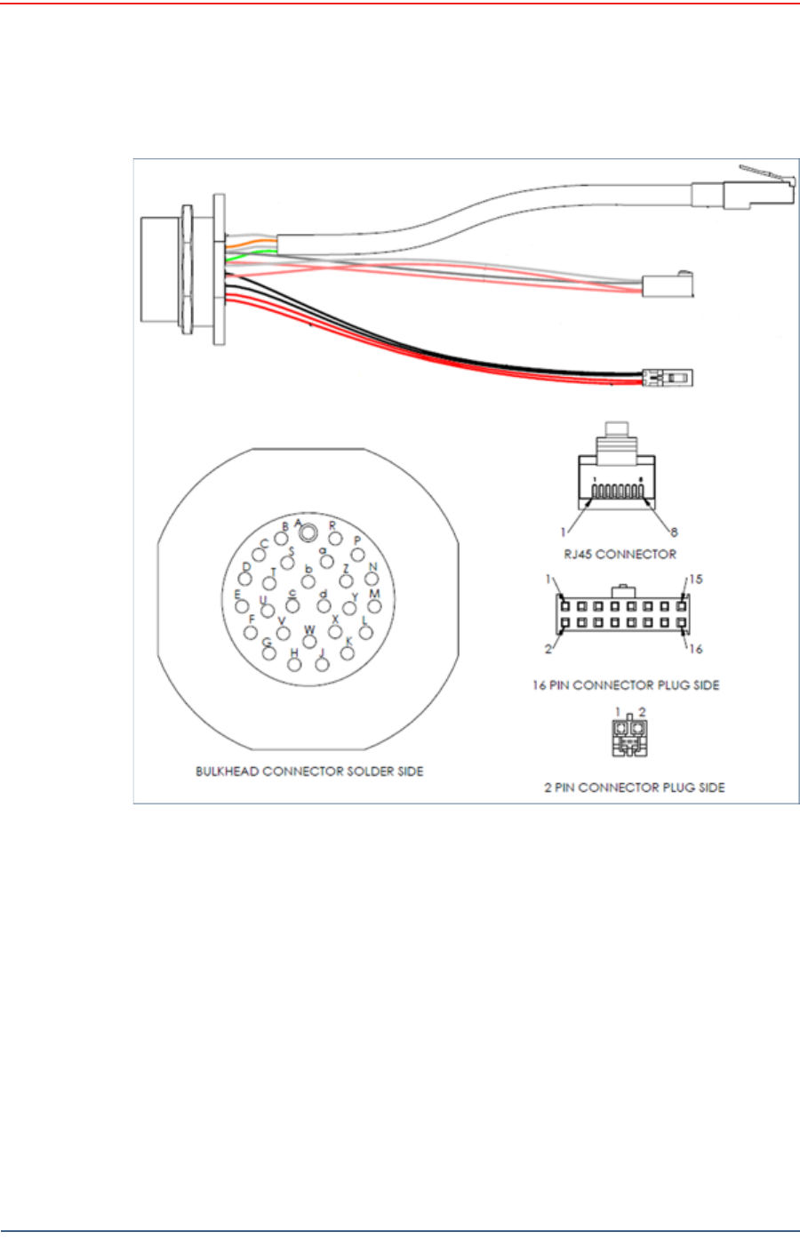
The following figures and tables show the signals on each pin for the three possible
cables used to connect an SIU to the CSS computer:
Table 2–1 BSU DATA-POWER Cable Pin List
Signal
Name Wire Color 27-Pin
Connector RJ45
Connector 16-Pin
Connector 2-Pin
Connector Twisted
Pair
TX+ WHT/ORG *
(WHT/GRN) R1——
Twisted Pair
TX- ORG *
(GRN) P 2 — —

Draft
14 RT 1000 v1.3 Deployment Guide R03.d
© 2010-2011 Wireless Seismic, Inc. All rights reserved.
Layout
Setting Up the Central Recording System
RX+ WHT/GRN *
(WHT/ORG) N3——
Twisted Pair
RX- GRN *
(ORG) M 6 — —
5V
EXTERNAL
NON ISO
START
RED B — 1 —
Twisted Pair
EXTERNAL
START
RETURN
BLK A — 2 —
EXT START
ISO OUT BLU E — 7 —
Twisted Pair
EXT START
ISO
RETURN
BLK U — 8 —
5V
TRIGGER IN
1
RED K — 15 —
Twisted Pair
TRIGGER 1
RETURN WHT X — 16 —
PWR RED b — — 1
PWR RED c — — 1
GND BLK a — — 2
GND BLK d — — 2
WHT = White, ORG = Orange, GRN = Green, BLU = Blue, BRN = Brown, BLK= Black, YEL = Yellow
* Connect per Pin Numbers
Wire colors in parenthesis are for Ethernet cable wired per T-586A standard.
Table 2–1 BSU DATA-POWER Cable Pin List (cont.)
Signal
Name Wire Color 27-Pin
Connector RJ45
Connector 16-Pin
Connector 2-Pin
Connector Twisted
Pair
Draft
R03.d RT 1000 v1.3 Deployment Guide 15
© 2010-2011 Wireless Seismic, Inc. All rights reserved.
Layout
Setting Up the Central Recording System
The following cable has not yet been implemented.
Figure 2–1 BSU DATA-POWER Cable

Draft
16 RT 1000 v1.3 Deployment Guide R03.d
© 2010-2011 Wireless Seismic, Inc. All rights reserved.
Layout
Setting Up the Central Recording System
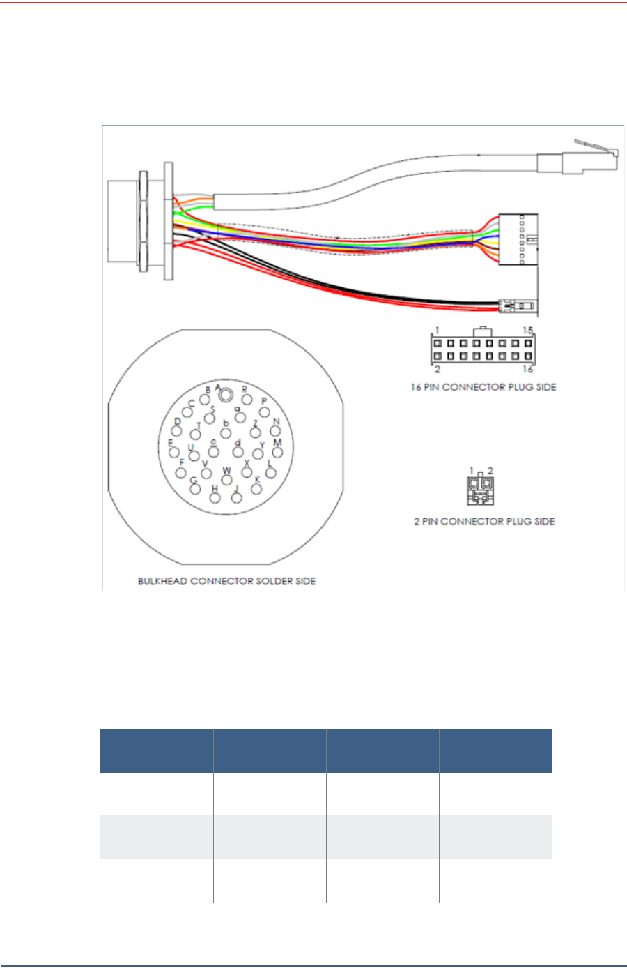
Table 2–2 SIU Source Control Cable Pin List
Signal Name Wire Color 27-Pin
Connector 16-Pin
Connector
5V0 EXTERNAL
START RED B 1
EXT. START
RETURN BLK A 2
RS232 TX OUT WHT C 3
RX/TX
RETURNS BLK S 6
RS232 RX IN GRN D 5
RX/TX
RETURNS BLK T 4
EXT START ISO
OUT BLU E 7
EXT START ISO
RETURN BLK U 8
GND DIG
(JUMPTRACK
NO)
YEL F 9
GND DIG
(JUMPTRACK
NO)
BLK G10
5V0 TRIGGER
IN 3 BRN H 11
TRIGGER
RETURN BLK V12
5V0 TRIGGER
IN 2 ORG J 13
TRIGGER
RETURN BLK W14
5V0 TRIGGER
IN 1 RED K 15
TRIGGER
RETURN WHT X16
—— L —
TX+ WHT/ORG*
(WHT/GRN) R 1
TXN ORG*
(GRN/WHT) P2

Draft
R03.d RT 1000 v1.3 Deployment Guide 17
© 2010-2011 Wireless Seismic, Inc. All rights reserved.
Layout
Setting Up the Central Recording System
RX+ WHT/GRN*
(WHT/ORG) N 3
RXY GRN*
(ORG/WHT) M6
— — Y —
——Z—
PWR RED c 1
PWR RED b 1
GND BLK a 2
GND BLK d 2
WHT = White, ORG = Orange, GRN = Green, BLU = Blue, BRN = Brown,
BLK= Black, YEL = Yellow
* Connect per Pin Numbers
Wire colors in parenthesis are for Ethernet cable wired per T-586A
standard.
Table 2–2 SIU Source Control Cable Pin List (cont.)
Signal Name Wire Color 27-Pin
Connector 16-Pin
Connector
Draft
18 RT 1000 v1.3 Deployment Guide R03.d
© 2010-2011 Wireless Seismic, Inc. All rights reserved.
Layout
Setting Up the Central Recording System
The following cable has not yet been implemented.
Figure 2–2 SIU Source Control Cable
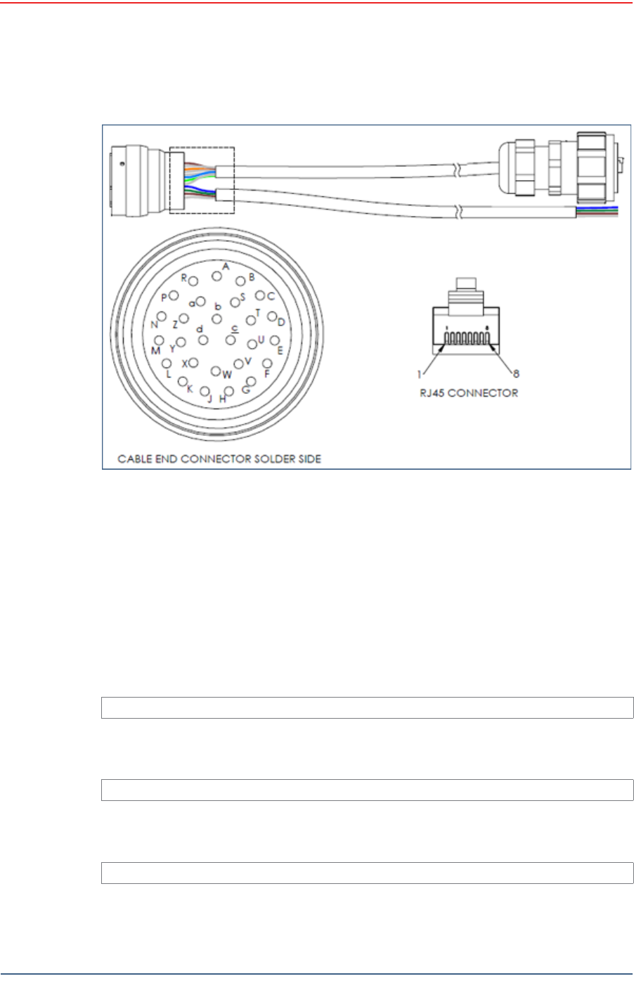
Table 2–3 BSU at Recording Truck Cable Pin List
Signal Name Wire Color 27-Pin
Connector RJ45
Connector
TX+ WHT/ORG *
(WHT/GRN) R1
TX- ORG *
(GRN/WHT) P 2
RX+ WHT/GRN *
(WHT/ORG) N3

Draft
R03.d RT 1000 v1.3 Deployment Guide 19
© 2010-2011 Wireless Seismic, Inc. All rights reserved.
Layout
Setting Up the Central Recording System
RX- GRN *
(ORG/WHT) M 6
PWR WHT/BLU
(WHT/BLU) b5
PWR BLU
(BLU) c 4
GND WHT/BRN
(WHT/BRN) a7
GND BRN
(BRN) d 8
Free Leads
5V EXTERNAL
NON ISO START BLU B –
RETURN
EXTERNAL NON
ISO START
GRN A –
5V TRIGGER IN
1BRN K –
TRIGGER 1
RETURN WHT X –
WHT = White, ORG = Orange, GRN = Green, BLU = Blue, BRN = Brown,
BLK= Black, YEL = Yellow
* Connect per Pin Numbers
Wire colors in parenthesis are for Ethernet cable wired per T-586A
standard.
Table 2–3 BSU at Recording Truck Cable Pin List (cont.)
Signal Name Wire Color 27-Pin
Connector RJ45
Connector
Draft
20 RT 1000 v1.3 Deployment Guide R03.d
© 2010-2011 Wireless Seismic, Inc. All rights reserved.
Layout
Laying Out the Equipment
2.5 Laying Out the Equipment
You can lay out the ground equipment while the central recording system
hardware and software is being prepared.
The WRU is shown in the following figure:
The BSU is shown in the following figure:
An example geophone is shown in the following figure
Figure 2–3 BSU at Recording Truck Cable
Illustration TBD
Figure 2–4 WRU
Illustration TBD
Figure 2–5 BSU
Illustration TBD
Figure 2–6 Geophone

Draft
R03.d RT 1000 v1.3 Deployment Guide 21
© 2010-2011 Wireless Seismic, Inc. All rights reserved.
Layout
Laying Out the Equipment
2.5.1 Prerequisites
You can attach the batteries, antennas, and geophones to the ground equipment
prior to going into to the field, or as you place each unit. If you are assembling as
you place the units, ensure that you have sufficient quantities for each unit, plus a
few spares.
The RT 1000 shall be used with only the supplied antennas (Table A–1 Antenna
Specifications, on page 85) attached to the WRU with an integrated type N male
connector.
The RT 1000 antennas shall be installed and handled by professionals
specifically designated for this purpose.
Changes or modifications not expressly approved by Wireless Seismic, Inc. can
void the users’s authority to operate the equipment.
2.5.2 Assembling the Ground Equipment
This section describes the process to assemble the ground equipment prior to
deployment.
To assemble the ground equipment:
1Gather the equipment:
●WRU or BSU
●Antenna
●Geophone
●Batteries
2Gather any special tools:
●Nylon grip pliers
●Loctite® 222
3Attach one or more batteries to the WRU or BSU.
●Press the battery into the connector.
●Flip the bail over the molded area on the end of the battery.
●Press the lever until the catch snaps to lock it in place.
WARNING
In order to comply with FCC radio frequency (RF) exposure
requirements, the RT 1000 units must be installed so that a minimum
separation distance of 20 cm is maintained between the antenna(s) and
all persons at all times during normal operation.

Draft
22 RT 1000 v1.3 Deployment Guide R03.d
© 2010-2011 Wireless Seismic, Inc. All rights reserved.
Layout
Laying Out the Equipment
4Attach the geophone to the WRU.
Figure 2–7 Battery Latch
Figure 2–8 Installing the Battery

Draft
R03.d RT 1000 v1.3 Deployment Guide 23
© 2010-2011 Wireless Seismic, Inc. All rights reserved.
Layout
Laying Out the Equipment
5Attach the antenna (use Loctite 222) to the WRU or BSU using nylon grip
pliers.
2.5.3 Placing the WRU in the Field
This section describes the process to ready the ground equipment for interaction
with the central recording system (deployment).
To deploy the WRU:
1Prerequisites:
●The WRU is assembled with battery, geophone, and antenna
Figure 2–9 Installing the
Geophone
TBD
Figure 2–10 Installing the Antenna
TIP
When determining which antenna to use (5 dBi, 7 dBi, 9dBi), consider
the distance between WRUs, and how much vegetation is in the area.
For distances of 10 m to 30 m, use a 5 dBi antenna.
Distances of 30 m or greater, use a 7 dBi or 9dBi antenna.
For sudden elevation changes, such as cliffs, use a 2 dBi or 5 dBi
antenna.
Draft
24 RT 1000 v1.3 Deployment Guide R03.d
© 2010-2011 Wireless Seismic, Inc. All rights reserved.
Layout
Laying Out the Equipment
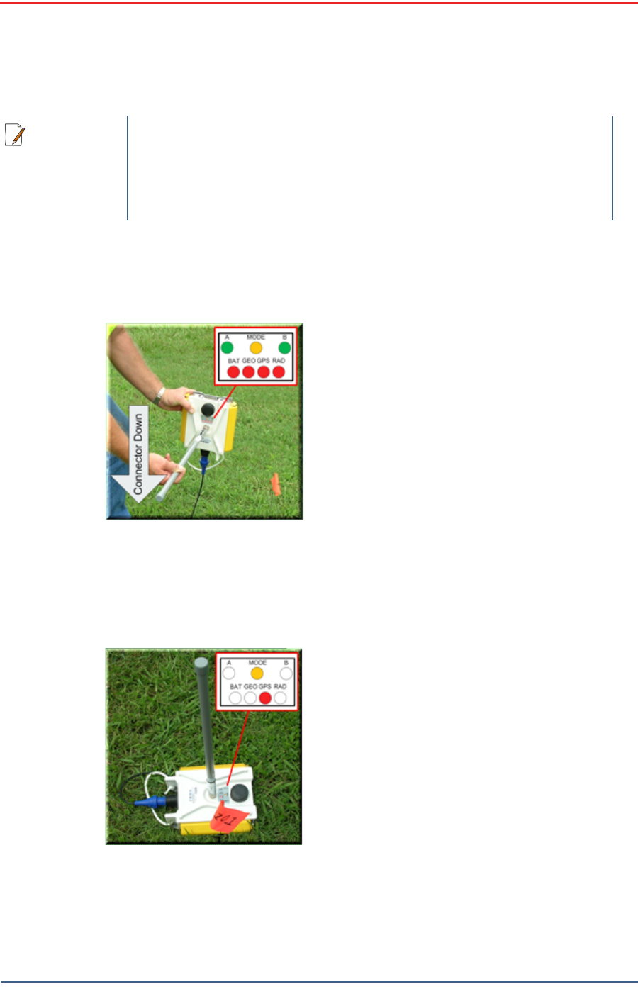
2Pick up the WRU and point the geophone connector end towards the ground as
shown in the following figure. After a few seconds, all of the LEDs illuminate:
3Place the unit flat on the ground as shown in the following figure:
NOTE
If you are using a WRU as a Repeater, the deployment instructions are
the same, except a geophone is not required.
If a geophone is not connected, you can skip the geophone test. See
“LED Indicators” on page 93 for more information on skipping the test
and the relevant LED status indicators.
Figure 2–11 Power on the
Unit
Figure 2–12 Place the Unit

Draft
R03.d RT 1000 v1.3 Deployment Guide 25
© 2010-2011 Wireless Seismic, Inc. All rights reserved.
Layout
Laying Out the Equipment
4The unit will begin a series of internal and external tests. The LEDs on the top
of the unit indicate the current test and whether the unit passes or fails each
test.
2.5.4 Placing the BSU in the Field
The BSU is part of the backhaul configuration. See “Backhaul” on page 27 for more
information.
NOTE
See “LED Indicators” on page 93 for an explanation of the LED status
and error conditions.

Draft
RT 1000 v1.3 26 Deployment Guide R03.d
© 2010-2011 Wireless Seismic, Inc. All rights reserved.
3
Software
3.1 Overview
For this release, your computer hardware and ground electronics comes with
all software installed.
3.2 Installing the Software
TBD
3.3 Upgrading the Software
TBD
3.4 Upgrading the Firmware
TBD

Draft
RT 1000 v1.3 27 Deployment Guide R03.d
© 2010-2011 Wireless Seismic, Inc. All rights reserved.
4
Backhaul
4.1 Overview
In network communications, the backhaul is the part of the network that
contains the links and equipment between the core network and the sub
networks.
Wireless mesh networking is a method where each radio node in the network
captures and disseminates its own data as well as serves as a relay for other
radio nodes in the network sending data along a path, hopping from one node
to the next.
Power over Ethernet (PoE) is a technology that passes electrical power along
an Ethernet cable. PoE is used where DC power is not available and USB
unsuitable. Power can be supplied at the end of a network span or somewhere
in the middle. PoE switches supply power at the end of a span. PoE injectors
supply power somewhere between the PoE switch and the powered device.
They inject power and do not affect the data.
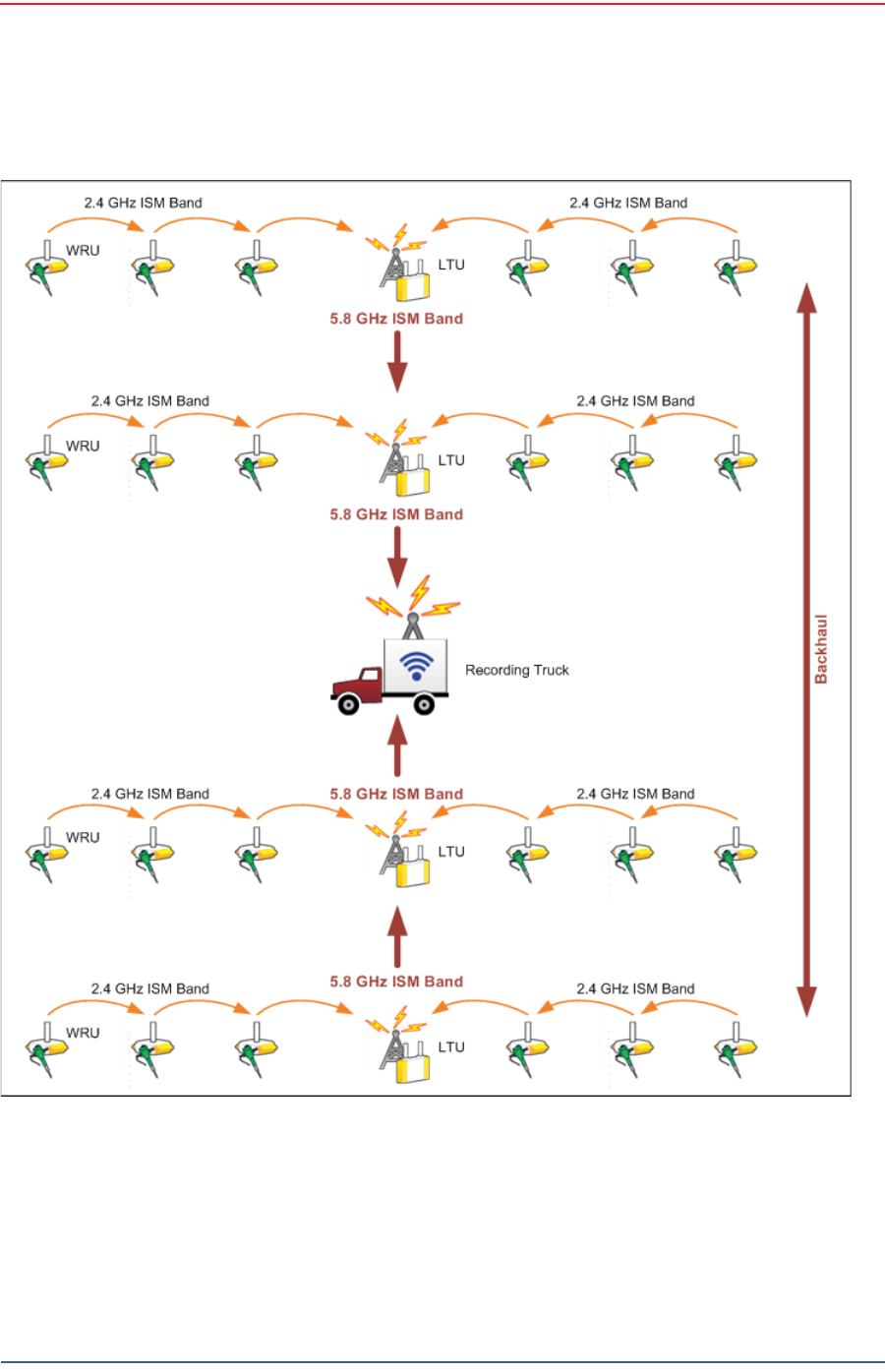
The RT 1000 Central Recording System is a fully connected mesh network of
Wireless Remote Units (WRUs) that communicate in a routing pattern (bucket-
brigade or string-of-pearls) with a Line Tap Unit (LTU) on the 2.4 GHz
Industrial, Scientific, and Medical (ISM) radio band.
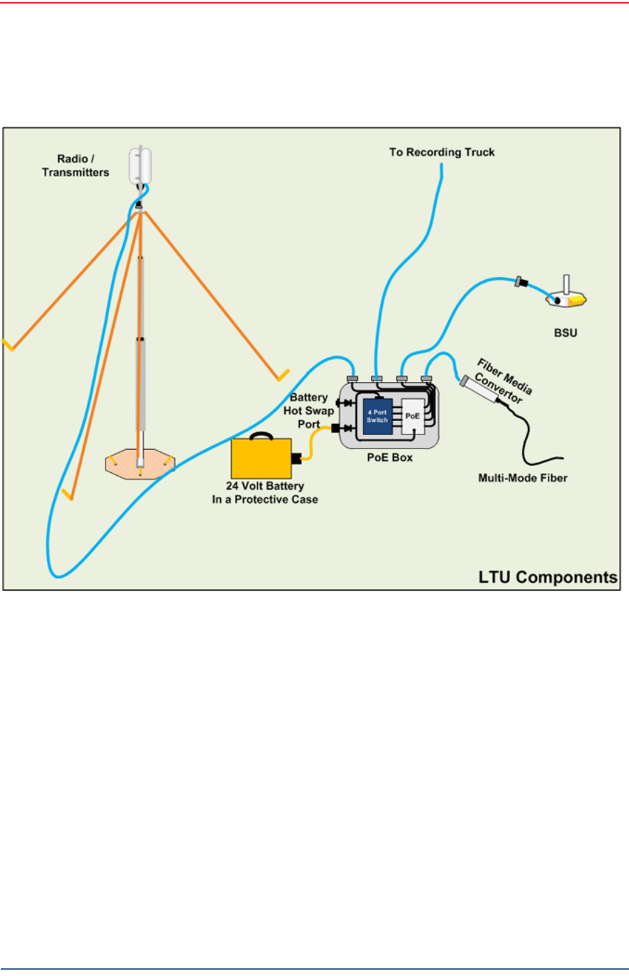
The LTU is composed of the following:
Base Station Unit (BSU)
Power over Ethernet (PoE)
24 V Battery or Power Supply
Cables
Mast, mast base, and guy-wires
5.8 GHz backhaul radios
Antennas
The LTU communicates by way of the BSU with the Central Software System
(CSS) computer in the central recording truck along a backhaul on the 5.8 GHz
ISM radio band.
The Central Software System (CSS) communicates with the field units via the
backhaul radios. The backhaul radios act as access points for the BSUs.
Draft
28 RT 1000 v1.3 Deployment Guide R03.d
© 2010-2011 Wireless Seismic, Inc. All rights reserved.
Backhaul
Overview
The following figure illustrates the possible LTU components:
Figure 4–1 Possible LTU Components
Draft
R03.d RT 1000 v1.3 Deployment Guide 29
© 2010-2011 Wireless Seismic, Inc. All rights reserved.
Backhaul
Overview
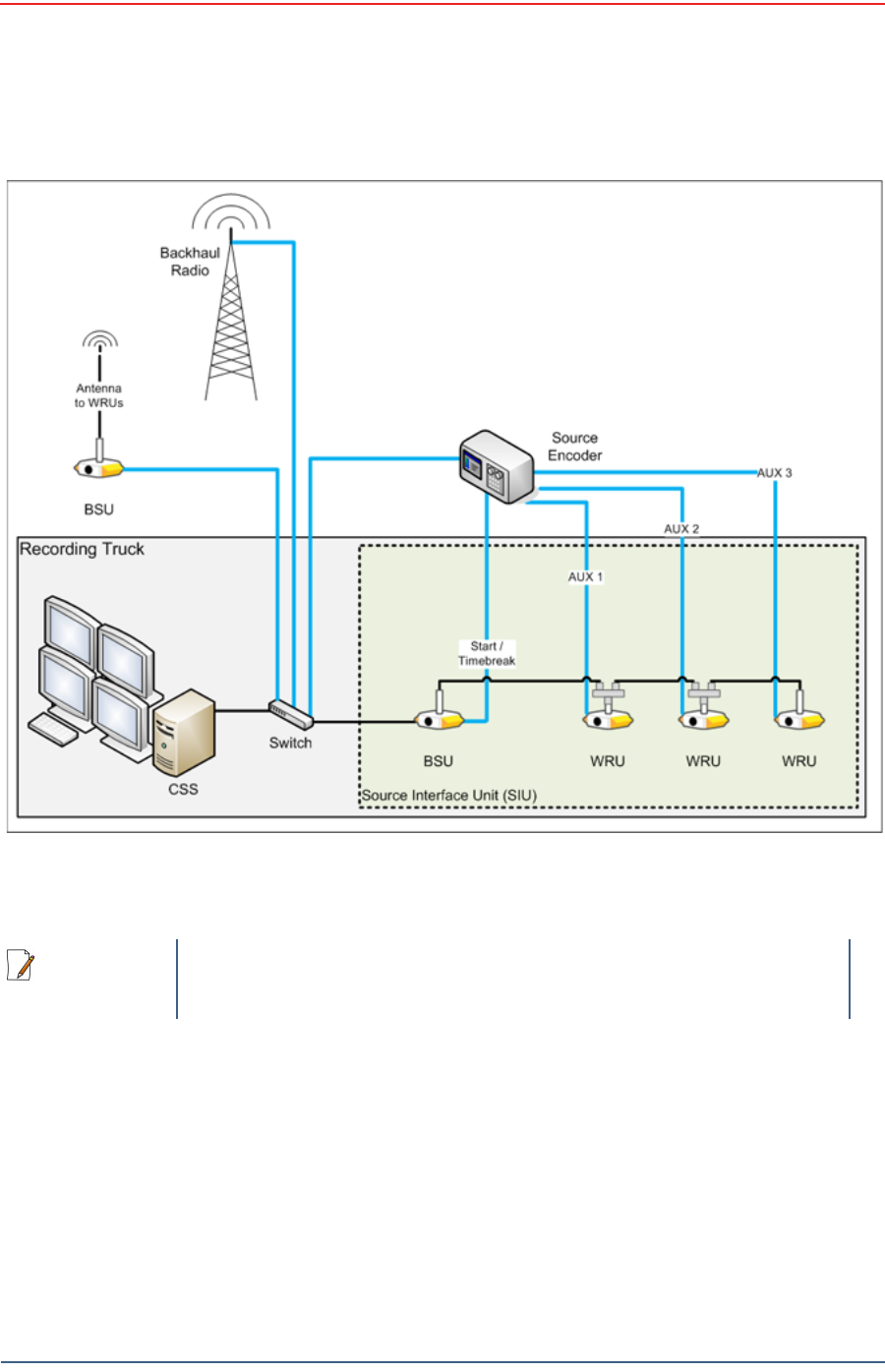
The following figure illustrates the central recording truck components:
The following figure illustrates the components and data flow for a four-line,
single-backhaul line with two root nodes example:
Figure 4–2 Central Recording Truck Components
NOTE
There can be from one to three WRUs in the Recording Truck as part of
the SIU.
Draft
30 RT 1000 v1.3 Deployment Guide R03.d
© 2010-2011 Wireless Seismic, Inc. All rights reserved.
Backhaul
Overview
Figure 4–3 Single Backhaul Data Direction

Draft
R03.d RT 1000 v1.3 Deployment Guide 31
© 2010-2011 Wireless Seismic, Inc. All rights reserved.
Backhaul
Backhaul Components
4.2 Backhaul Components
The backhaul components are either remote backhaul components or central
backhaul components. Remote components are the components that are not
physically located next to the recording truck. Central components are physically
located at the recording truck. Both remote and central backhauls are composed of
the following:
Base Station Unit (BSU) Kit
Antenna
Radio Kit
Mast Kit
The following figure shows the backhaul components packed for transport:
4.2.1 BSU Components
The following table lists the BSU kit components:
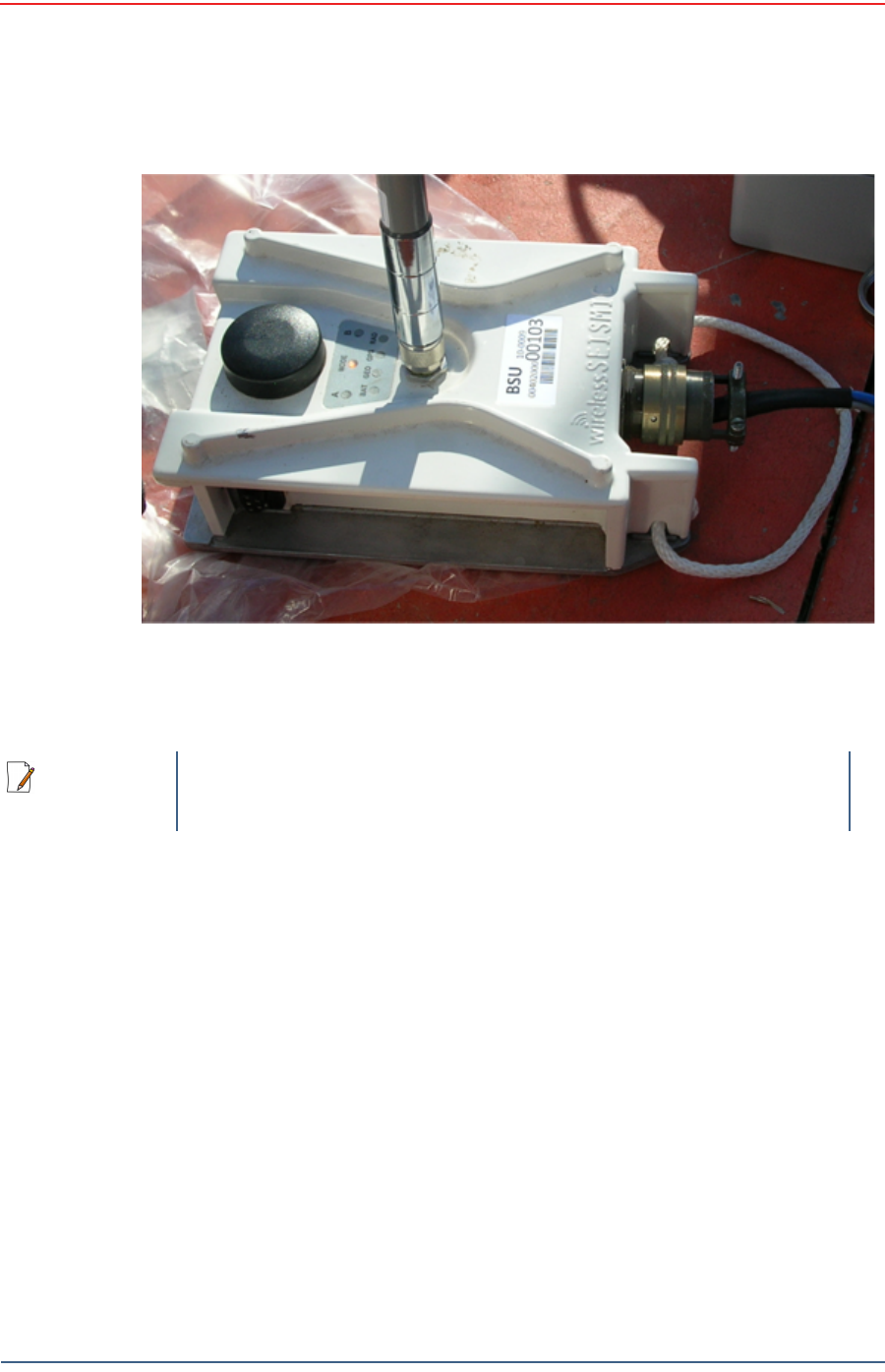
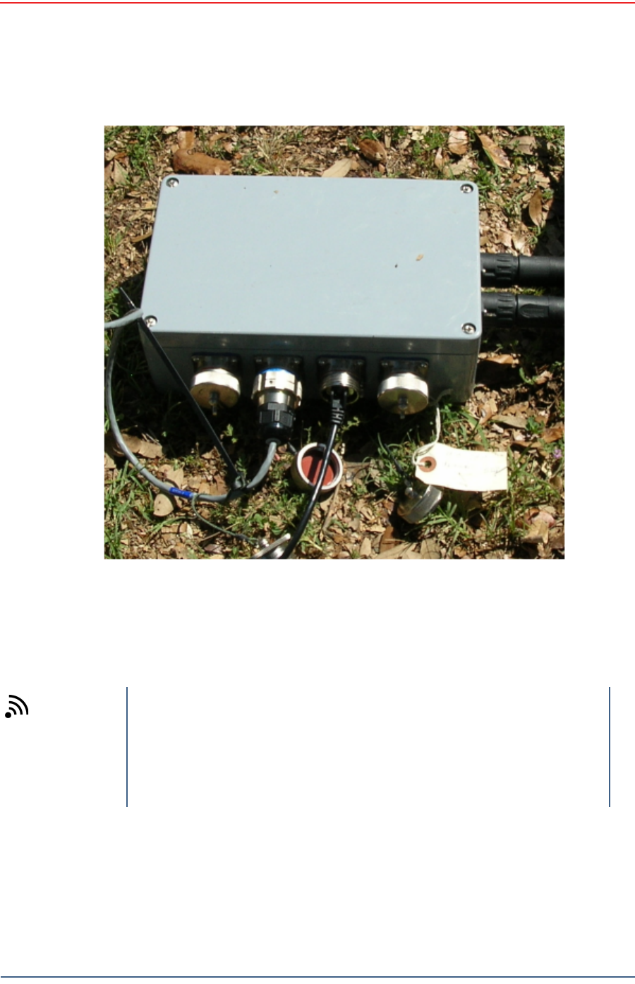
4.2.1.1 BSU
The Base Station Unit (BSU) is shown in the following figure:
TBD
Figure 4–4 Backhaul Components Packed for Transport
Table 4–1 Base Station Unit Kit
Remote Backhaul Components Central Backhaul Components
Item Reference Item Reference
BSU “BSU” on page
31 BSU “BSU” on page
31
PoE Switch Unit “PoE Switch
Unit” on page
32
PoE Switch Unit “PoE Switch
Unit” on page
32
Battery “Battery and
Power Supply”
on page 33
Power Supply, 24 V “Battery and
Power Supply”
on page 33
Cable Assembly, BSU-to-PoE
Switch “Cables” on
page 34 Cable Assembly, BSU at truck “Cables” on
page 34
Cable, PoE Switch-to-Battery “Cables” on
page 34 Cable, Power Supply-to-PoE “Cables” on
page 34
Ethernet Cable, 25 ft “Cables” on
page 34
Draft
32 RT 1000 v1.3 Deployment Guide R03.d
© 2010-2011 Wireless Seismic, Inc. All rights reserved.
Backhaul
Backhaul Components
Before the Central Software System can communicate with the BSU, you must set
up the backhaul.
4.2.1.2 PoE Switch Unit
Power over Ethernet (PoE) is a technology that passes electrical power along an
Ethernet cable. PoE is used where DC power is not available and USB unsuitable.
Power can be supplied at the end of a network span or somewhere in the middle.
PoE switches supply power at the end of a span. PoE injectors supply power
somewhere between the PoE switch and the powered device. They inject power
and do not affect the data.
The PoE is shown in the following figure:
Figure 4–5 Base Station Unit (BSU)
NOTE
See “LED Indicators” on page 93 for an explanation of the LED status
and error conditions.
Draft
R03.d RT 1000 v1.3 Deployment Guide 33
© 2010-2011 Wireless Seismic, Inc. All rights reserved.
Backhaul
Backhaul Components
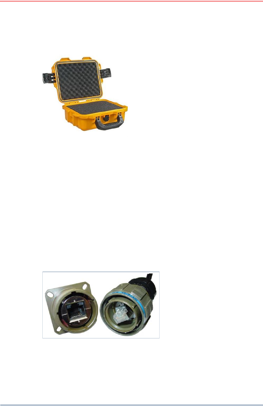
4.2.1.3 Battery and Power Supply
Power is supplied to the LTU components by way of a 24 Ah DC battery or power
supply.
Wireless Seismic, Inc. recommends using a protective battery case as shown in
the following figure:
Figure 4–6 PoE
TIP
The backhaul power requirements vary depending on the hardware in
use and period of use. For example, you may be using one or two
radios. Supply enough power to ensure there is enough power for the
entire duration of the time you are using the backhaul.
A 24 Ah battery is adequate if a recharged battery is installed for every
12 hours of use.
Draft
34 RT 1000 v1.3 Deployment Guide R03.d
© 2010-2011 Wireless Seismic, Inc. All rights reserved.
Backhaul
Backhaul Components
4.2.1.4 Cables
The following cables are used in the backhaul:
BSU-to-PoE Switch 27-pin to RJ45
BSU at Recording Truck 27-pin to RJ45
PoE Switch-to-Battery 2-pin to 2-pin
Power Supply-to-PoE
Ethernet Cable, 25 ft
TBD – Fiber Optic Cable
To ensure a protected connection, be sure to use an Ethernet cable with a
protective shell when connecting Ethernet cables to the PoE. An example is shown
in the following figure:
Figure 4–7 Protective Battery
Case
Figure 4–8 Protective Ethernet
Connector

Draft
R03.d RT 1000 v1.3 Deployment Guide 35
© 2010-2011 Wireless Seismic, Inc. All rights reserved.
Backhaul
Backhaul Components
4.2.2 Antennas
The following table lists the supported antennas for the BSUs and the WRUs. The
remote and central backhauls use the same antennas:
The Fluidmesh radios have built-in antennas (see “Radio Kit Components” on page
35 for details).
There is an auto-power-leveling feature built into the firmware. It works in
conjunction with the RSSI parameters to keep the power at a defined level.
4.2.3 Radio Kit Components
The following table lists the Radio Kit components:
Refer to the Fluidmesh datasheet for FCC information and other technical
specifications on the FM1100 and FM3100 radios. See one of the following
locations for details:
http://www.fluidmesh.com/press-room/product-literature/doc_details/160-
fluidmesh-mito-series
“Fluidmesh Radio Specifications” on page 87
Table 4–2 Antenna Specifications
Model Frequency
(MHz) Gain Vertical
Bandwidth Weight Dimension
(Length x
Diameter)
WSI 65-0067 2400-2485 9 dbi 14° 0.8 lbs
0.5 kg 27 x 0.6 in
690 x 15 mm
WSI 6060-001-01 2400-2485 7 dBi 18° 0.6 lbs
0.3 kg 21 x 0.6 in
540 x 15 mm
WSI 65-0023 2400-2485 5 dBi 25º 0.5 lbs
0.2 kg 12 x 0.6 in
355 x 15 mm
WSI 65-0025 2400-2485 2 dBi @ 2.4 120° 1.6 oz
45.4 g 7.6 x 0.5 in
193 x 12.7 mm
Table 4–3 Radio Kit
Remote Backhaul Components Central Backhaul Components
Item Reference Item Reference
Radio, Fluidmesh® FM1100 “FM1100
Radio” on page
37
Radio, Fluidmesh® FM3100 “FM1100
Radio” on page
37
Software, Fluidmesh®
FM1100-30 “FM3100
Radio” on page
37
Software, Fluidmesh®
FM3100-30 “FM3100
Radio” on page
37
Draft
36 RT 1000 v1.3 Deployment Guide R03.d
© 2010-2011 Wireless Seismic, Inc. All rights reserved.
Backhaul
Backhaul Components
The Fluidmesh radios can operate on at 4.9 GHz, and 5.1 - 5.8 GHz. The preferred
frequency is configured through a user interface (see “Configure the Radios” on
page 43 for instructions).
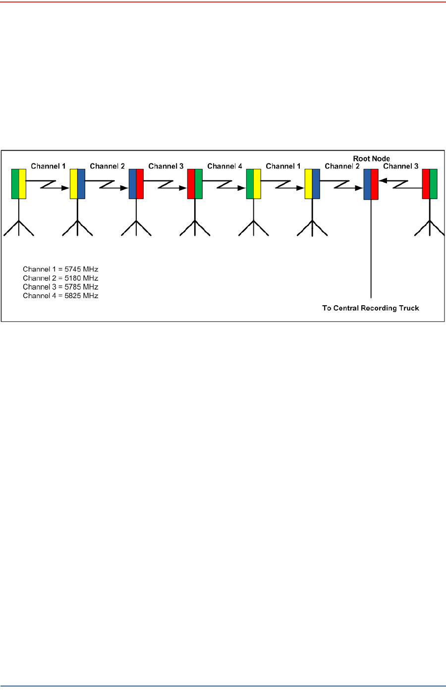
Each radio is assigned a color that represents the channel assignment, allowing
field personnel to quickly orient the radios in the proper direction. An example is
shown in the following figure:
The Fluidmesh default IP address is 192.168.0.10.
Figure 4–9 Channel Color Example
Draft
R03.d RT 1000 v1.3 Deployment Guide 37
© 2010-2011 Wireless Seismic, Inc. All rights reserved.
Backhaul
Backhaul Components
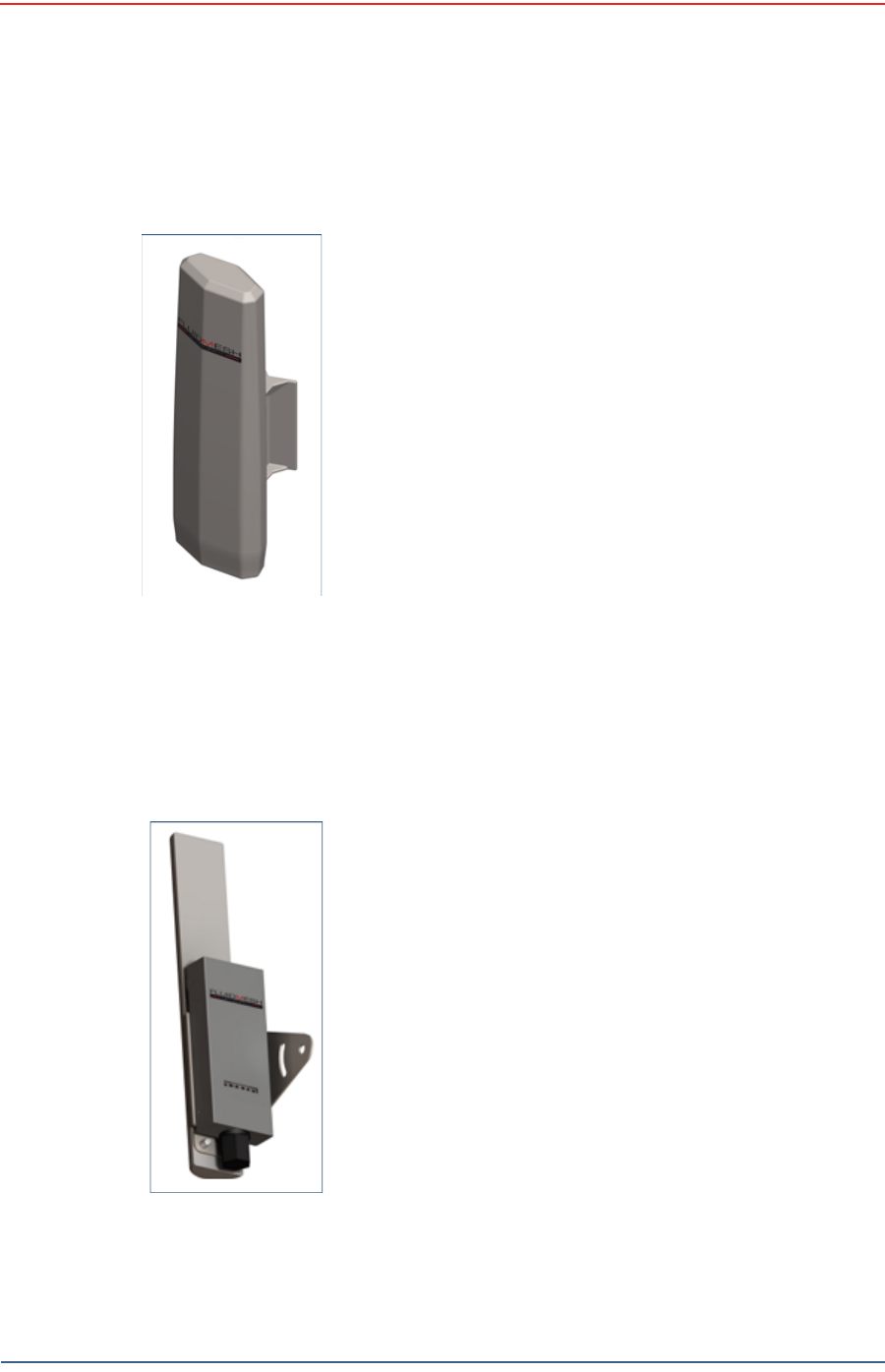
4.2.3.1 FM1100 Radio
The FM1100 radio is used on the masts for the remote backhauls and is shown in
the following figure:
4.2.3.2 FM3100 Radio
The FM3100 is used on the masts for the central backhaul unit and is shown in the
following figure:
Figure 4–10 FM1100
Radio
Figure 4–11 FM3100
Radio

Draft
38 RT 1000 v1.3 Deployment Guide R03.d
© 2010-2011 Wireless Seismic, Inc. All rights reserved.
Backhaul
Backhaul Components
4.2.4 Mast Kit Components
The following table lists the Mast Kit components. The remote and central
backhauls use the same mast kit components:
Table 4–4 Mast Kit
Remote Backhaul Components
Item Reference
Mast “Mast” on page 39
Base “Base” on page 39
Base, weighted “Base” on page 39
Bag “Bag” on page 42
Ethernet Cable, 25 ft (2 each) “Cables” on page 34
Backpack Kit “Backpack Kit” on page
42
• 1 each backpack “Backpack Kit” on page
42
• 3 each guy lines, rope, orange, 15.25 meters “Backpack Kit” on page
42
• 3 each tent stake, steel, 12 in (hard ground stakes) “Backpack Kit” on page
42
• 3 each tent stake, plastic, orange, 16 in (soft
ground stakes) “Backpack Kit” on page
42
• 5 ea nail, 12 in “Backpack Kit” on page
42
• 3 each guy line holder “Backpack Kit” on page
42
•1 each hammer, 2.5 lb “Backpack Kit” on page
42
• 1 each pry bar, 15 in “Backpack Kit” on page
42
• 2 each flagging roll, orange “Backpack Kit” on page
42
• 1 each compass sighting “Backpack Kit” on page
42
• 5 each hose clamp, 2 in “Backpack Kit” on page
42
• 1 each electronics carrier “Mast” on page 39
Draft
R03.d RT 1000 v1.3 Deployment Guide 39
© 2010-2011 Wireless Seismic, Inc. All rights reserved.
Backhaul
Backhaul Components
4.2.4.1 Mast
Lightweight, telescoping backhaul masts are used to elevate the backhaul
components above obstructions and to enable radio communications to
accommodate typical cross-line distances. The mast can be installed by a single
person. The following figures show the mast components:
4.2.4.2 Base
There are two base options; one that requires the use of guy wires for stabilization
and one that uses weights for stabilization.
Figure 4–12 Mast
TBD
Figure 4–13 Electronics Carrier

Draft
40 RT 1000 v1.3 Deployment Guide R03.d
© 2010-2011 Wireless Seismic, Inc. All rights reserved.
Backhaul
Backhaul Components
The following figures show the base that utilizes guy-wires:
Figure 4–14 Base
Draft
R03.d RT 1000 v1.3 Deployment Guide 41
© 2010-2011 Wireless Seismic, Inc. All rights reserved.
Backhaul
Backhaul Components
The following figure shows the assembled mast with the BSU in the foreground:
The following figure shows the base that uses a weighted system. This base is
optimal in urban or rocky environments:
Figure 4–15 Assembled Backhaul Mast

Draft
42 RT 1000 v1.3 Deployment Guide R03.d
© 2010-2011 Wireless Seismic, Inc. All rights reserved.
Backhaul
Backhaul Components
4.2.4.3 Bag
The antenna mast bag is a rip stop nylon yellow bag, 11 inches x 70 inches with a
handle and draw string at one end (see Figure 4–4 Backhaul Components Packed
for Transport on page 31).
4.2.4.4 Backpack Kit
The backpack is used to carry all of the equipment needed to install the mast and
radios, and may also be use to carry the BSU. See “Mast Kit” on page 38 for a list
of components (see Figure 4–4 Backhaul Components Packed for Transport on
page 31).
Figure 4–16 Base (70-0070)

Draft
R03.d RT 1000 v1.3 Deployment Guide 43
© 2010-2011 Wireless Seismic, Inc. All rights reserved.
Backhaul
Configure the Radios
4.3 Configure the Radios
The FMQuadro™ Web Interface is used to configure the radio channels. The radio
licenses are pre-configured by Wireless Seismic, Inc. This section describes how to
connect the radios to a computer and configure them.
Check the radios before connecting them to any switch.
4.3.1 Create a Private Network
Create a private network between the computer and the Fluidmesh radio.
1Prerequisites:
●Windows computer
●Browser with Adobe Flash
●AC Power
●PoE Injector
●Two Ethernet Cables
2Power on the computer.
3Connect the components (see Figure 4–17 Fluidmesh Radio Private Network on
page 44):
●Plug the PoE injector into an AC outlet.
●Connect the computer to the PoE injector with an Ethernet cable.
●Connect the Fluidmesh radio to the PoE injector with an Ethernet cable. The
radio powers up.
►FM1100 – Connect to LAN 1
►FM3100 – There is only one connector
NOTE
The expected configuration in the RT 1000 system is as follows:
FM1100 = mesh point (remote backhaul)
FM3100 = mesh end (central backhaul)
NOTE
All Fluidmesh units are preconfigured with an IP address of
192.168.0.10.
CAUTION
Power up only one radio at a time. Never place two powered-up radios
next to each other. It is possible to damage the radio receivers if
multiple radios are powered up in close proximity.
Draft
44 RT 1000 v1.3 Deployment Guide R03.d
© 2010-2011 Wireless Seismic, Inc. All rights reserved.
Backhaul
Configure the Radios
4Verify that the radio powers up. The LED indicators have the following
meanings:
5Click the Windows Start icon.
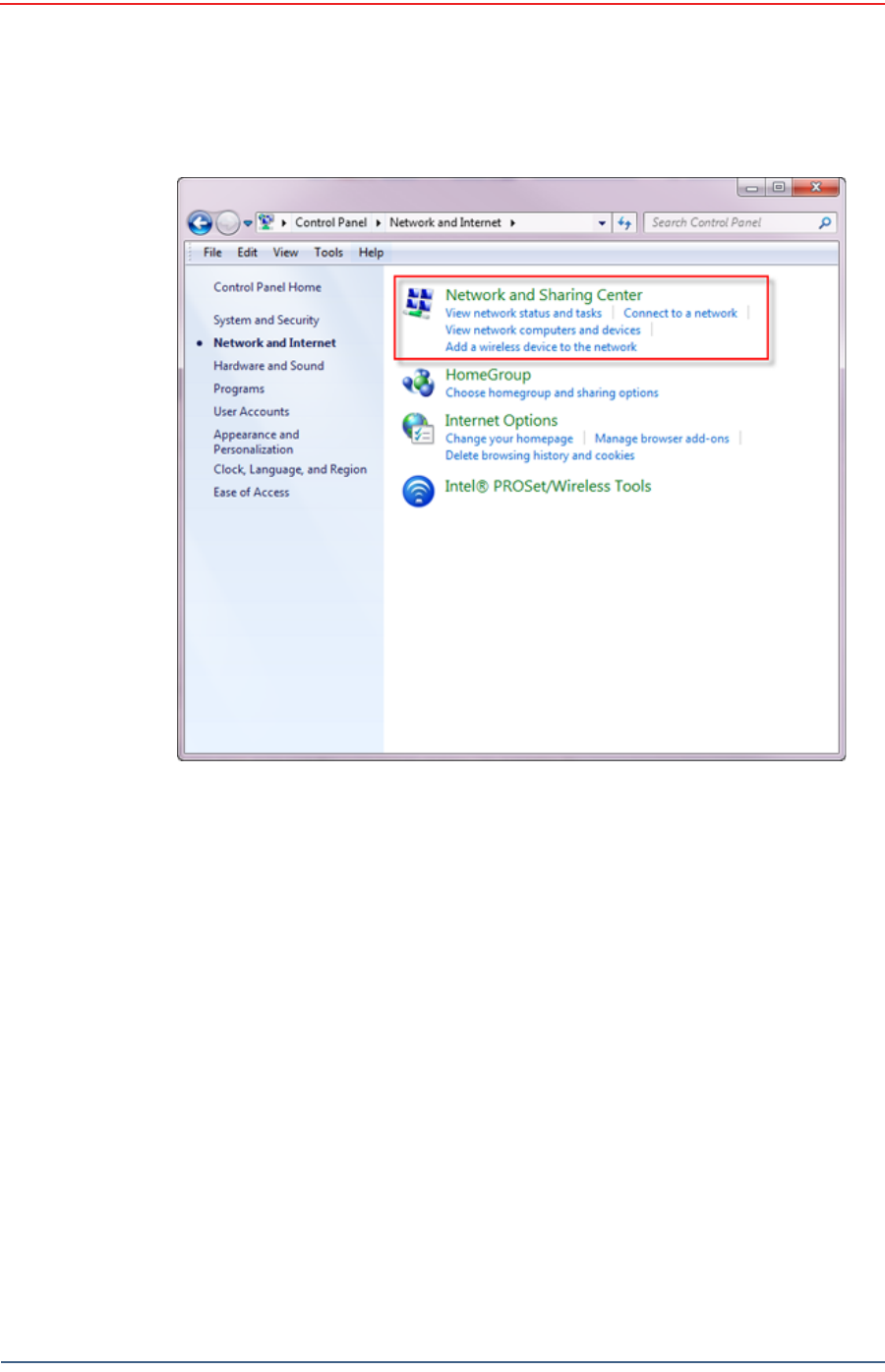
6Select Control Panel. The Control Panel window opens.
7Select Network and Internet.
Figure 4–17 Fluidmesh Radio Private Network
Table 4–5 Fluidmesh Radio LEDs
LED State Description
Power On / Green On whenever the radio has
power
LAN On / Green On whenever the radio has an
Ethernet connection
Signal Strength (1) On / Red BootingCoresystem
Signal Strength (2) On / Orange Bootingwirelesssystem
Signal Strength (3) On / Green Bootingroutingengine
Signal Strength (4) On / Green Bootingunitconfiguration
Draft
R03.d RT 1000 v1.3 Deployment Guide 45
© 2010-2011 Wireless Seismic, Inc. All rights reserved.
Backhaul
Configure the Radios
8Select Network and Sharing Center.
Figure 4–18 Control Panel, Network and Internet
Draft
46 RT 1000 v1.3 Deployment Guide R03.d
© 2010-2011 Wireless Seismic, Inc. All rights reserved.
Backhaul
Configure the Radios
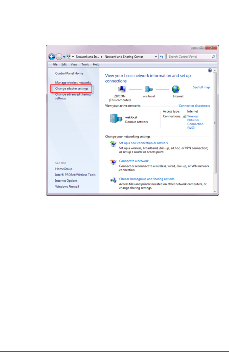
9In the left pane, select Change adapter settings.
Figure 4–19 Control Panel, Network and Sharing Center
Draft
R03.d RT 1000 v1.3 Deployment Guide 47
© 2010-2011 Wireless Seismic, Inc. All rights reserved.
Backhaul
Configure the Radios
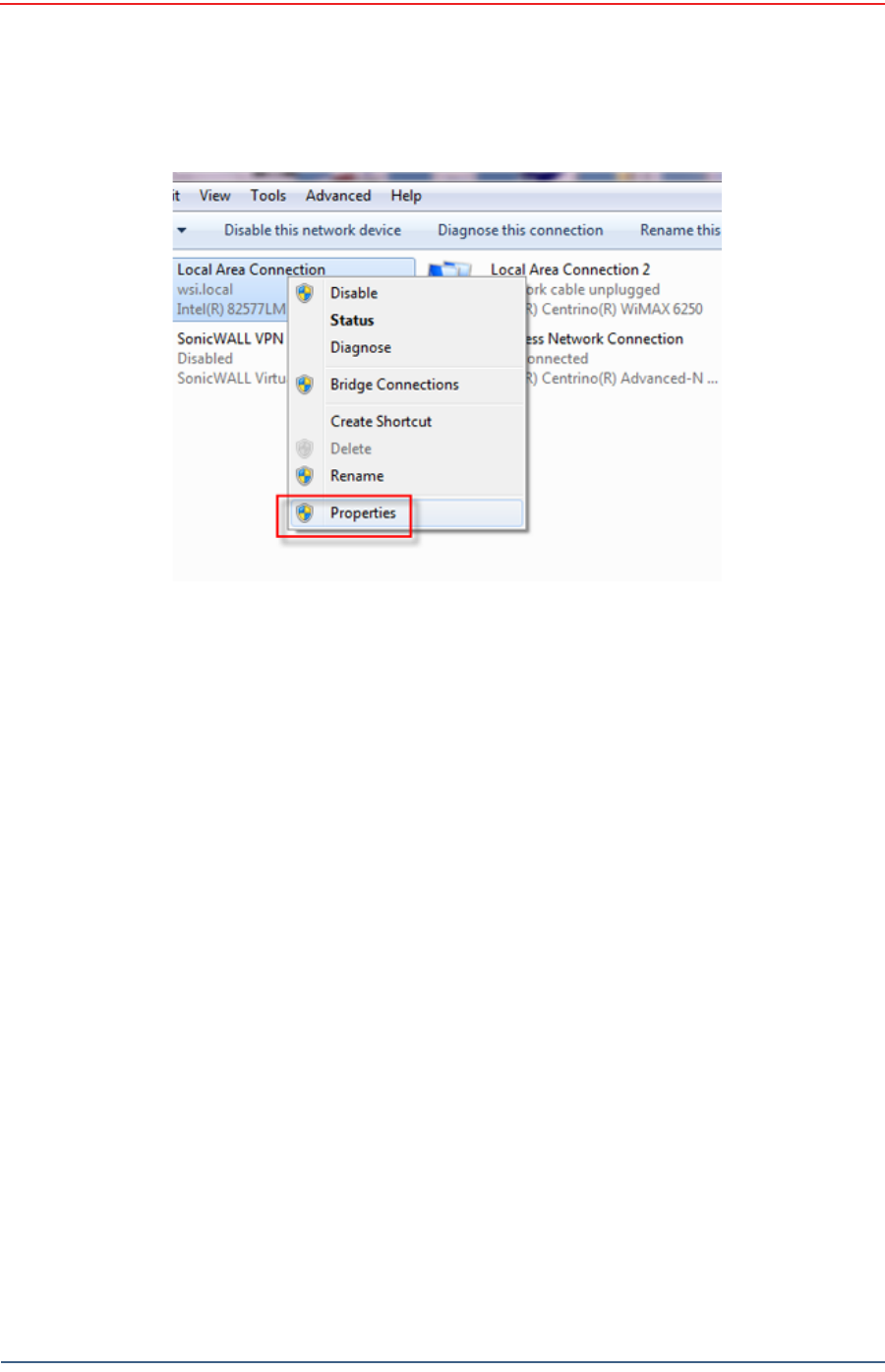
10 Right-click Local Area Connection and select Properties. The Properties
window opens.
Figure 4–20 Control Panel, Change Adapter Settings
Draft
48 RT 1000 v1.3 Deployment Guide R03.d
© 2010-2011 Wireless Seismic, Inc. All rights reserved.
Backhaul
Configure the Radios
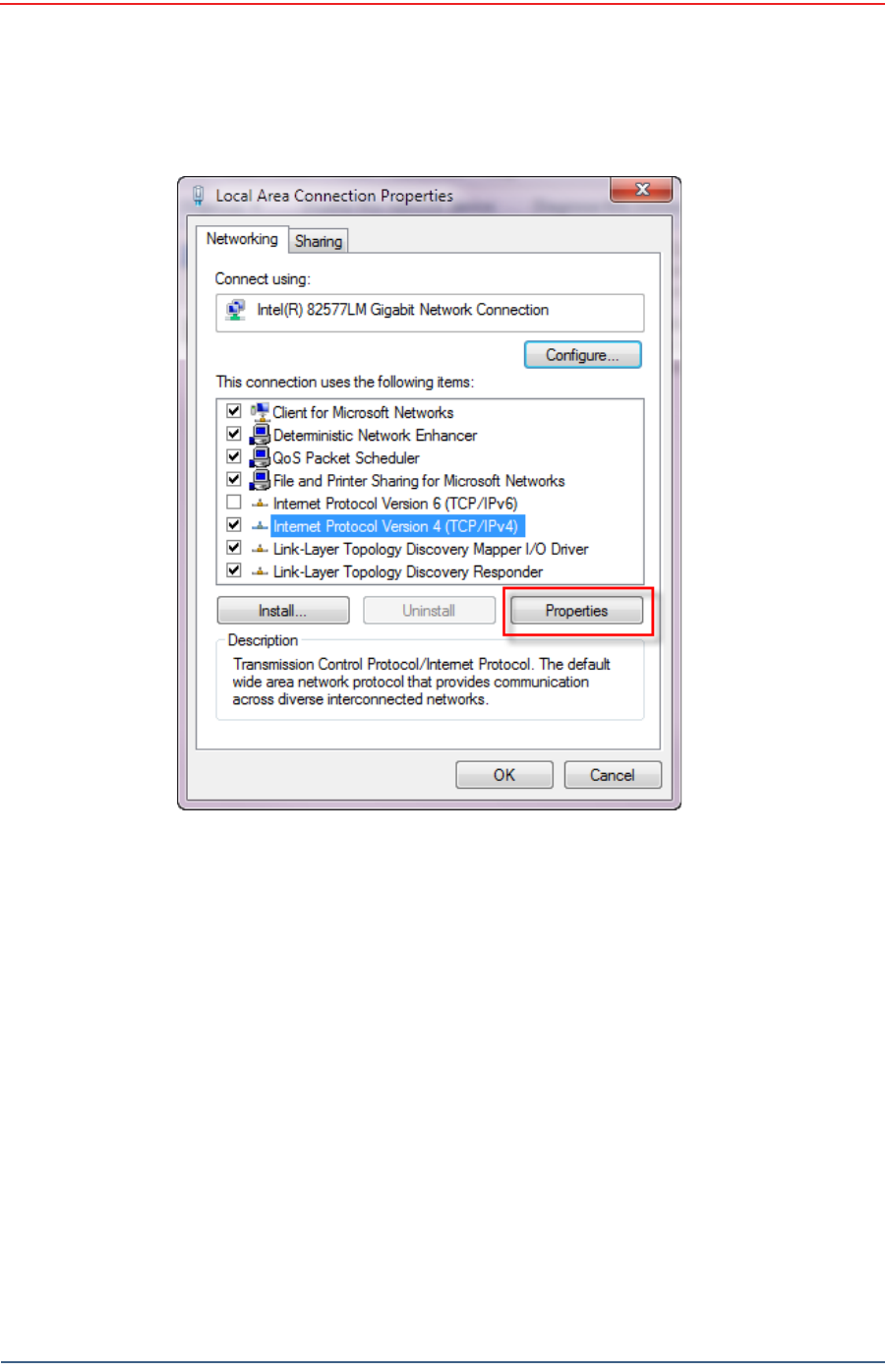
11 Select Internet Protocol Version 4 (TCP/IP v4) and click Properties.
Figure 4–21 Control Panel, LAN Properties
Draft
R03.d RT 1000 v1.3 Deployment Guide 49
© 2010-2011 Wireless Seismic, Inc. All rights reserved.
Backhaul
Configure the Radios
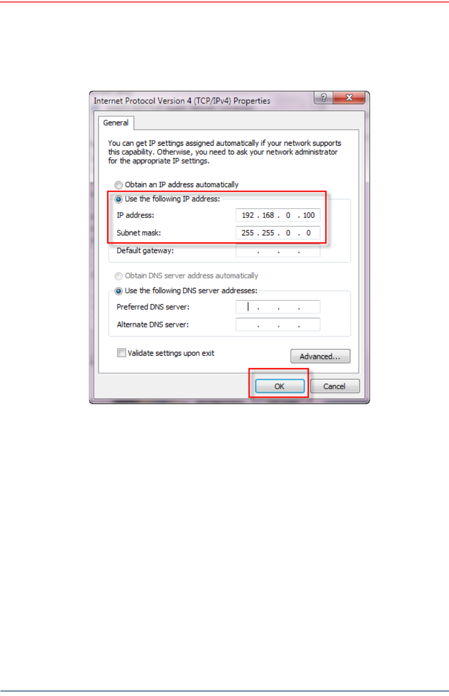
12 Select Use the following IP address.
Figure 4–22 Control Panel, Networking Properties
Draft
50 RT 1000 v1.3 Deployment Guide R03.d
© 2010-2011 Wireless Seismic, Inc. All rights reserved.
Backhaul
Configure the Radios
13 Enter the following:
●IP address: 192.168.0.100 (this number does not have to be 100, just
something other than 10, and a number between 1 and 255)
●Netmask:255.255.255.0
Figure 4–23 Control Panel, IP Address

Draft
R03.d RT 1000 v1.3 Deployment Guide 51
© 2010-2011 Wireless Seismic, Inc. All rights reserved.
Backhaul
Configure the Radios
14 Click OK.
15 Click Close.
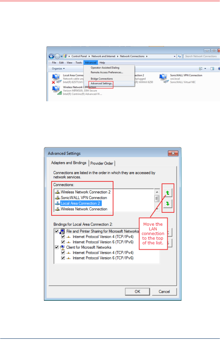
4.3.2 Setting NIC Priority
If you have more than one network interface card (NIC) in your computer, make
sure that the LAN card has the highest priority; the computer attempts to use the
NICs in the order listed.
To set NIC priority:
→Windows computer
1Click the Windows Start icon.
2Select Control Panel. The Control Panel window opens.
3Select Network and Internet.
4Select Network and Sharing Center.
5In the left pane, select Change adapter settings.
6In the toolbar, click Advanced, and then Advanced Settings.
NOTE
If the radio already has an IP address, you will need to enter different
numbers. For example:
Radio IP address: 10.101.0.22
Computer IP address: 10.168.0.100
Subnet Mask: 255.0.0.0
You may need to disable and enable (right-click) the LAN connection if
it displays Network cable unplugged in the Network Connections
window.
If the radio gets reset, the default IP address is 192.168.0.10.
Draft
52 RT 1000 v1.3 Deployment Guide R03.d
© 2010-2011 Wireless Seismic, Inc. All rights reserved.
Backhaul
Configure the Radios
7Select Local Area Connection and then click the up arrow repeatedly until
Local Area Connection is the first item.
Figure 4–24 Advanced Network Settings Menu
Figure 4–25 LAN Hierarchy
Draft
R03.d RT 1000 v1.3 Deployment Guide 53
© 2010-2011 Wireless Seismic, Inc. All rights reserved.
Backhaul
Configure the Radios
8Click OK.
4.3.3 Configure the Radio
Configure the radios by logging into the software located on the radio. FM1100s
are configured as mesh points, and FM3100s are configured as mesh ends.
To configure the radio:
→Windows computer
1On the computer, point a browser to the following URL:
http://192.168.0.10
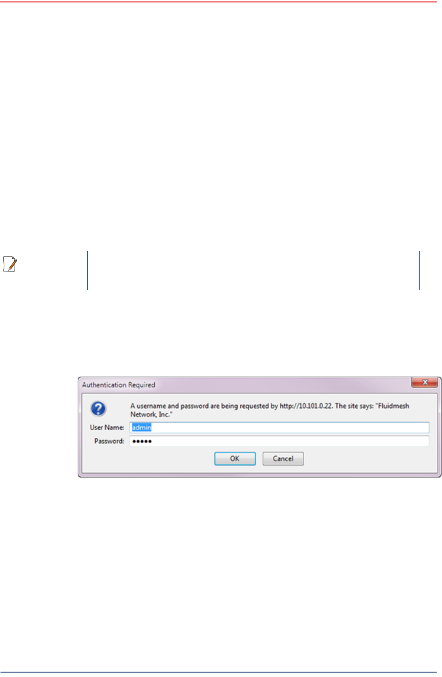
2Log in to the radio Web interface using the following:
●UserName: admin
●Password: admin
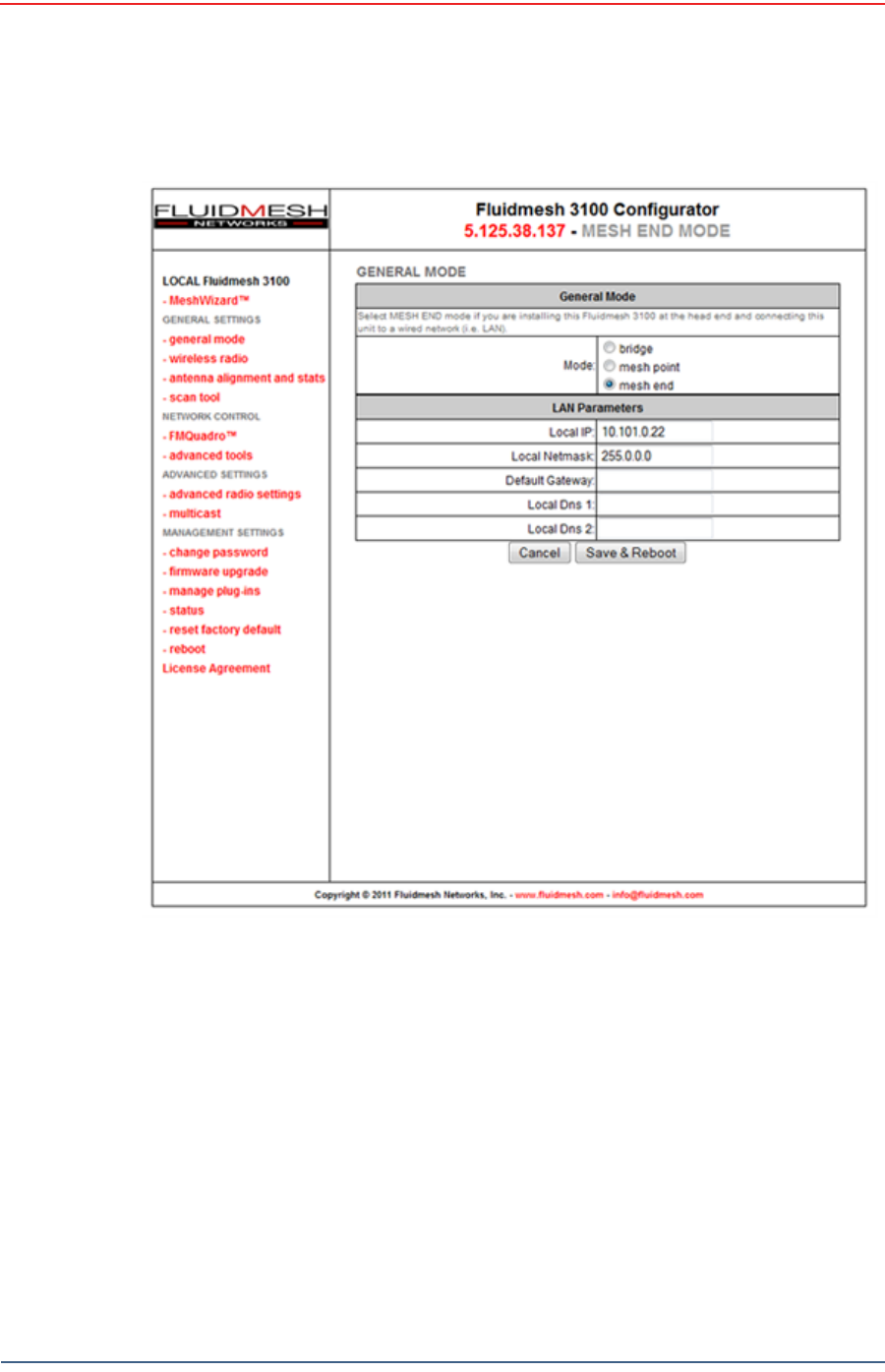
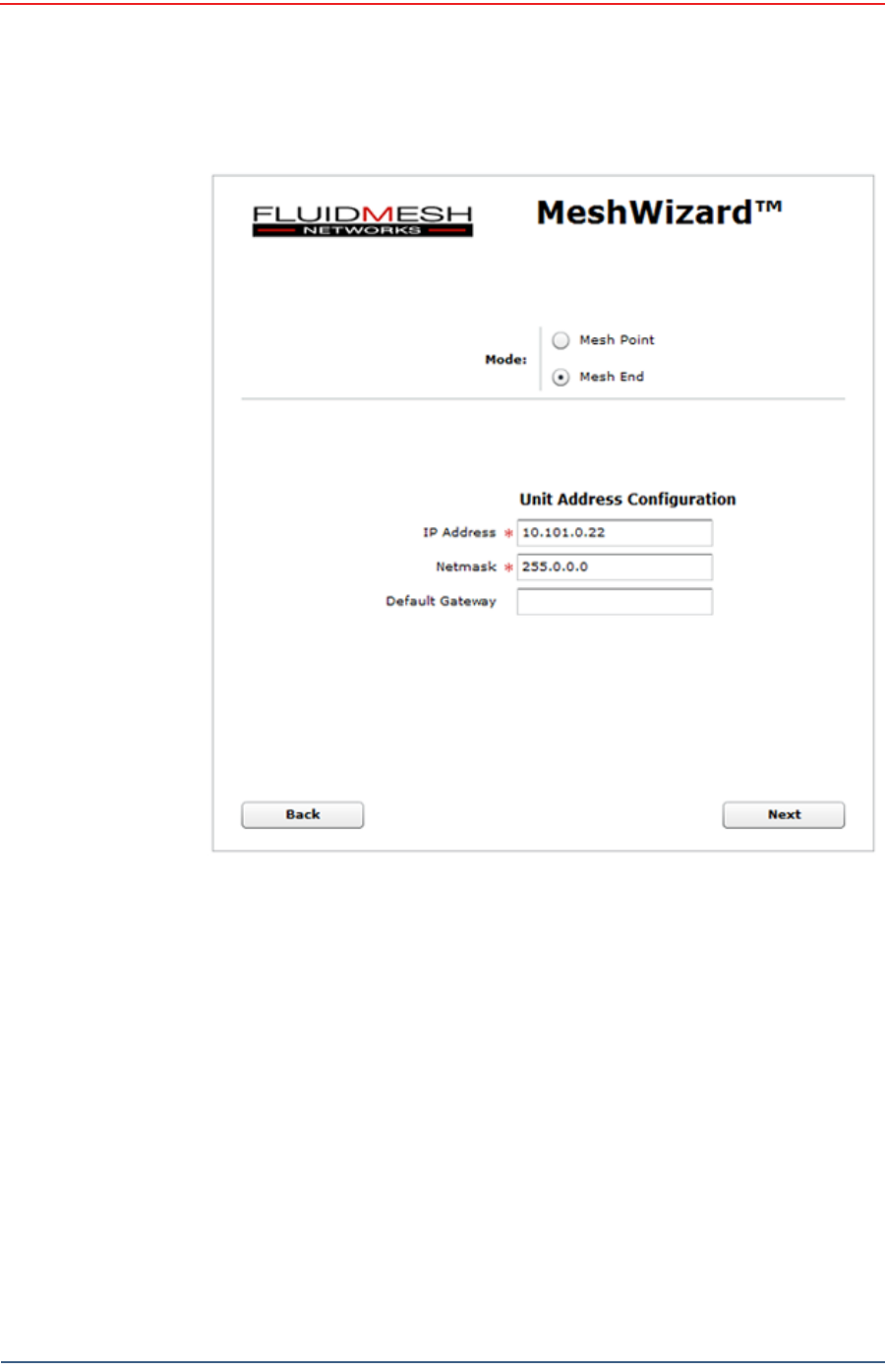
3The following figure shows the home window when mesh end is selected as
the Mode. The FM1100 configuration includes an additional left-pane option:
Power Over Ethernet. Click MeshWizard™.
NOTE
If the radio has an IP address other than the default IP address, you will
need to enter that number. For example, 10.101.0.22.
Figure 4–26 Radio Login Window
Draft
54 RT 1000 v1.3 Deployment Guide R03.d
© 2010-2011 Wireless Seismic, Inc. All rights reserved.
Backhaul
Configure the Radios
4Click I Agree to accept the licence agreement if prompted.
5Click Wizard.
6Select or enter the following:
●Mode – Mesh Point (FM1100), Mesh End (FM3100)
●IP Address – Use next class A address available (10.2.0.1 - 10.2.0.255)
●Netmask – 255.0.0.0
●Default Gateway – Leave blank (FM3100), not shown (FM1100)\
Figure 4–27 Radio Home Window, Mesh End
Draft
R03.d RT 1000 v1.3 Deployment Guide 55
© 2010-2011 Wireless Seismic, Inc. All rights reserved.
Backhaul
Configure the Radios
7Click Next.
8Select one of the following frequencies (see Figure 4–9 Channel Color Example
on page 36):
●Channel 1 = 5745 MHz (Yellow label)
●Channel 2 = 5805 MHz (Blue label)
●Channel 3 = 5180 MHz (Red label)
●Channel 4 = 5785 MHz (Green label)
9Click Next.
10 Verify the settings. Click Save&Reboot.
Figure 4–28 Fluidmesh MeshWizard Interface

Draft
56 RT 1000 v1.3 Deployment Guide R03.d
© 2010-2011 Wireless Seismic, Inc. All rights reserved.
Backhaul
Setting up the Backhaul Equipment
11 FM1100 only: Click Power Over Ethernet in the left pane. This option allows
the LAN 2 port on the radio to deliver passive PoE to a second FM1100 on the
mast using one short Ethernet cable.
12 FM1100 only: Click Enable.
4.3.4 Restore your Network Settings
When have finished configuring all of your radios, restore your network settings as
described in this section.
To restore network settings:
→Windows computer
1Click the Windows Start icon.
2Select Control Panel. The Control Panel window opens.
3Select Network and Internet.
4Select Network and Sharing Center.
5In the left pane, select Change adapter settings.
6Right-click Local Area Connection and select Properties. The Properties
window opens.
7Select Internet Protocol Version 4 (TCP/IP v4) and click Properties.
8Select Obtain IP address automatically.
9Click OK.
10 Click Close.
4.4 Setting up the Backhaul Equipment
Use the following procedure to erect and secure the mast that uses guy lines (55-
0007).
To install the backhaul components and erect the mast:
1Prerequisites:
●TBD
2Refer to the deployment instructions to determine the location and compass
heading to the next back haul site closer to central.
3Use the compass to determine and mark that direction.
4Locate the base such that the three guy lines and the mast clear obstructions
during erection and while in operation.
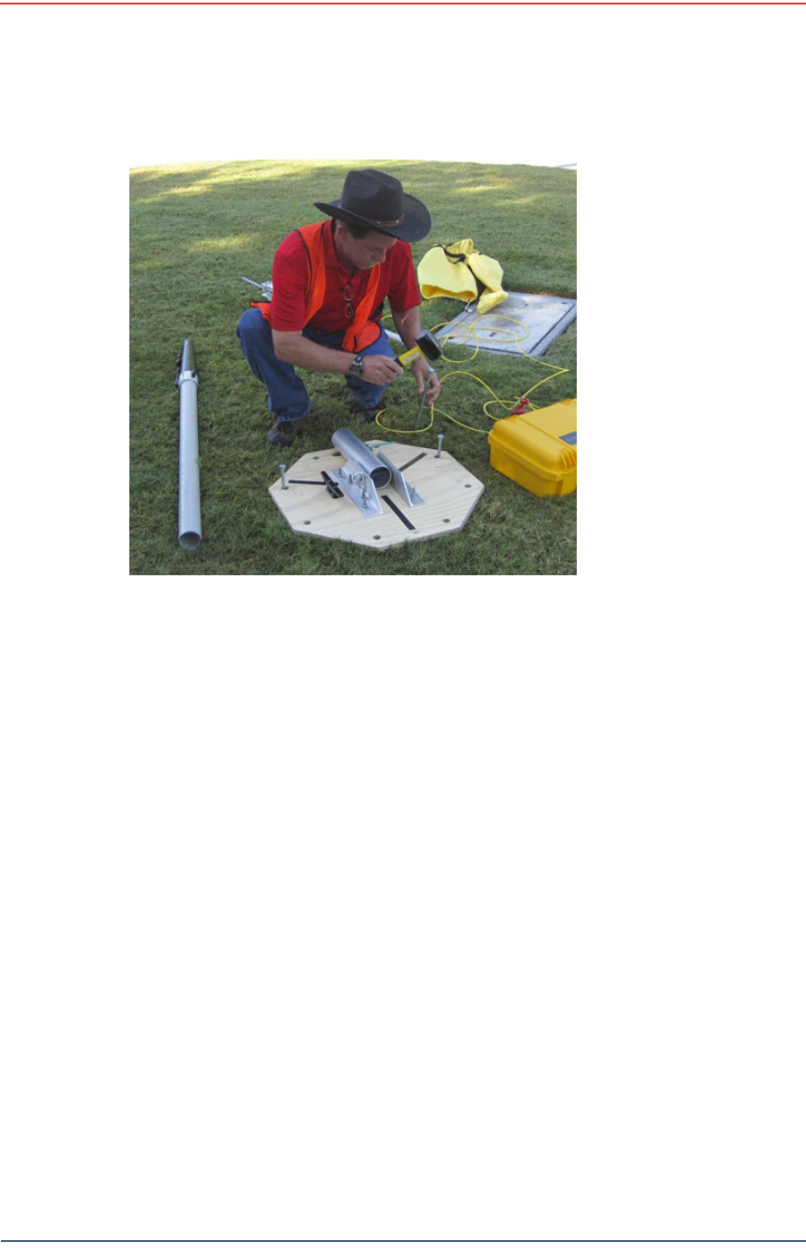
5Remove the mast and electronics carrier from the transport bag and empty the
backpack.

Draft
R03.d RT 1000 v1.3 Deployment Guide 57
© 2010-2011 Wireless Seismic, Inc. All rights reserved.
Backhaul
Setting up the Backhaul Equipment
6Secure the base with at least 2 nails.
Figure 4–29 Unpacking the Backhaul Equipment
Draft
58 RT 1000 v1.3 Deployment Guide R03.d
© 2010-2011 Wireless Seismic, Inc. All rights reserved.
Backhaul
Setting up the Backhaul Equipment
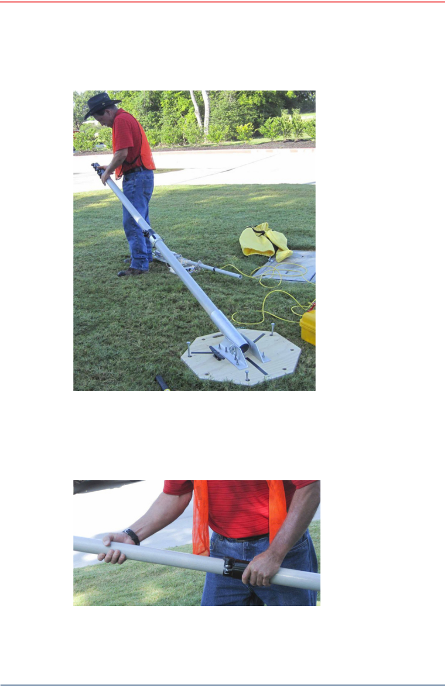
7Insert the mast into the base collar, extend and secure each section of the
mast at the mark on each section.
Figure 4–30 Securing the Base
Draft
R03.d RT 1000 v1.3 Deployment Guide 59
© 2010-2011 Wireless Seismic, Inc. All rights reserved.
Backhaul
Setting up the Backhaul Equipment
8Insert the electronics carrier with guy line collar into the top of the mast.
Figure 4–31 Inserting the Mast into the Base and
Extending the Mast
Figure 4–32 Inserting the Electronics Carrier into
the Mast
Draft
60 RT 1000 v1.3 Deployment Guide R03.d
© 2010-2011 Wireless Seismic, Inc. All rights reserved.
Backhaul
Setting up the Backhaul Equipment
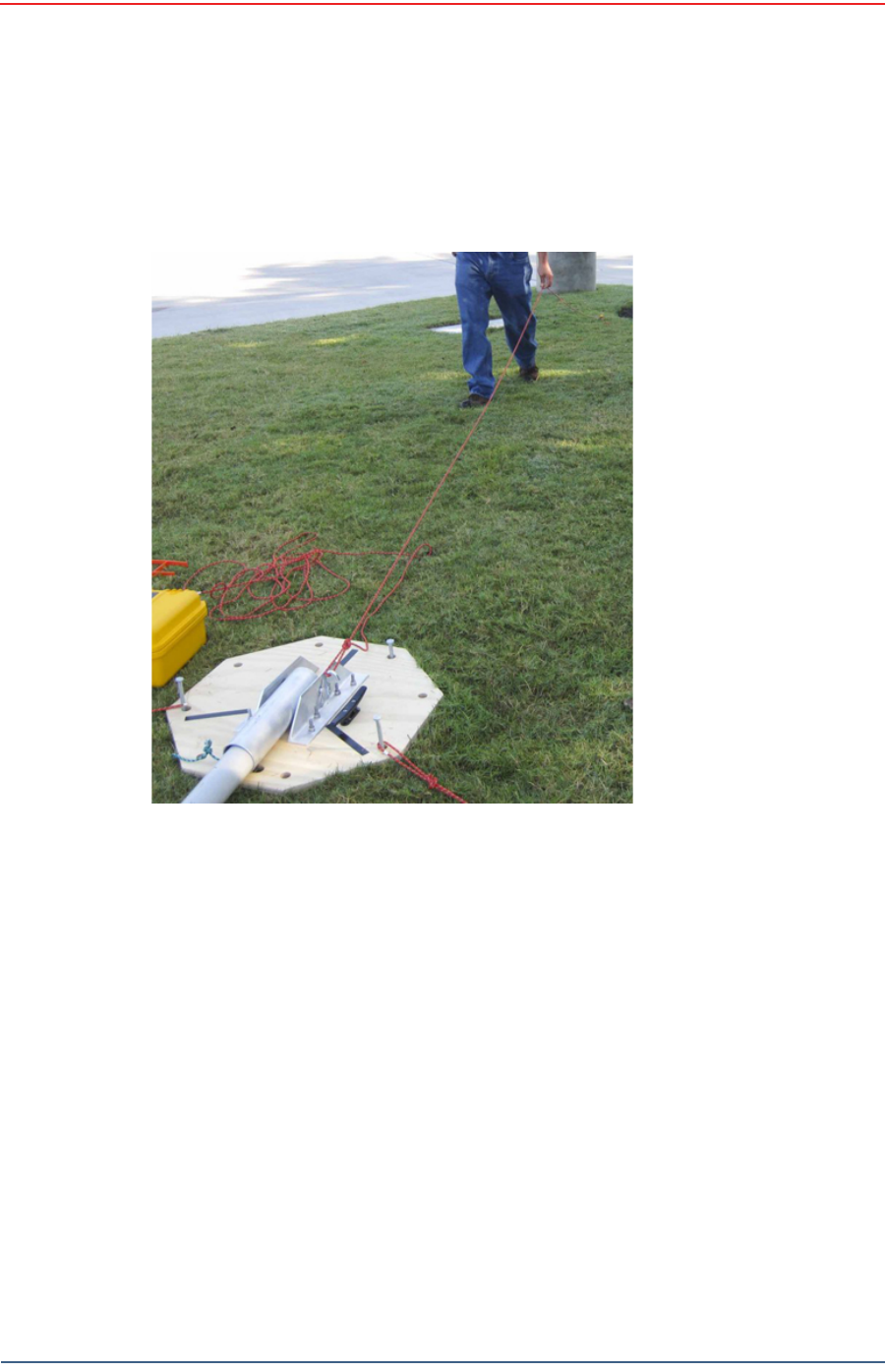
9Secure each guy line to the mast base at the loop in the guy line. Markings on
the ropes indicate the recommended distance for the stakes and the lines on
the base show the direction for the guy lines.
10 Hammer guy line stakes into ground and secure guy lines at the indicated
marks.
Figure 4–33 Securing Guy Line to Base