Wireless Seismic 00401 Base Station Unit User Manual DeploymentGuide
Wireless Seismic, Inc. Base Station Unit DeploymentGuide
Contents
- 1. Users Manual 1
- 2. Users Manual 2
Users Manual 2

Draft
R03.d RT 1000 v1.3 Deploym ent Guide 61
© 2010- 2011 Wir eless Seism ic, I nc. All right s reserved.
Backhaul
Set t ing up t he Backhaul Equipm ent
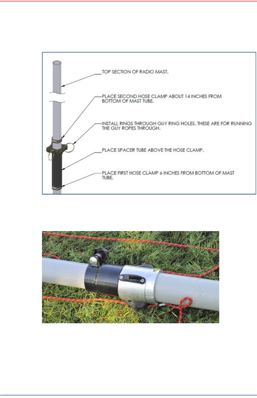
1 1 At t ach a radio t o t he elect ronics carrier.
1 2 Uncoil an Ethernet cable, at tach one end t o a radio unit and the ot her end to
the PoE. Form a service loop ( ext ra cable) by looping t he Ethernet cable over
the t op of t he radio unit. I f you are installing two radios on t he m ast , refer to
“ I nst alling Two Radios on the Mast ” on page 69 for cabling and configuration
inst ructions.
1 3 Ensur e t hat all direct ional antennas, when raised, are point ed correct ly. The
radio unit should be facing t oward t he recording t ruck.
1 4 Thread guy lines through t he guy line collar on t he electronics carrier and
thread t hrough cleat s on t he bott om m ast tube.
Figure 4 – 3 4 H a m m e r ing Guy Line St a k es
Draft
62 RT 1000 v1.3 Deploym ent Guide R03.d
© 2010- 2011 Wir eless Seism ic, I nc. All right s reserved.
Backhaul
Setting up the Backhaul Equipment
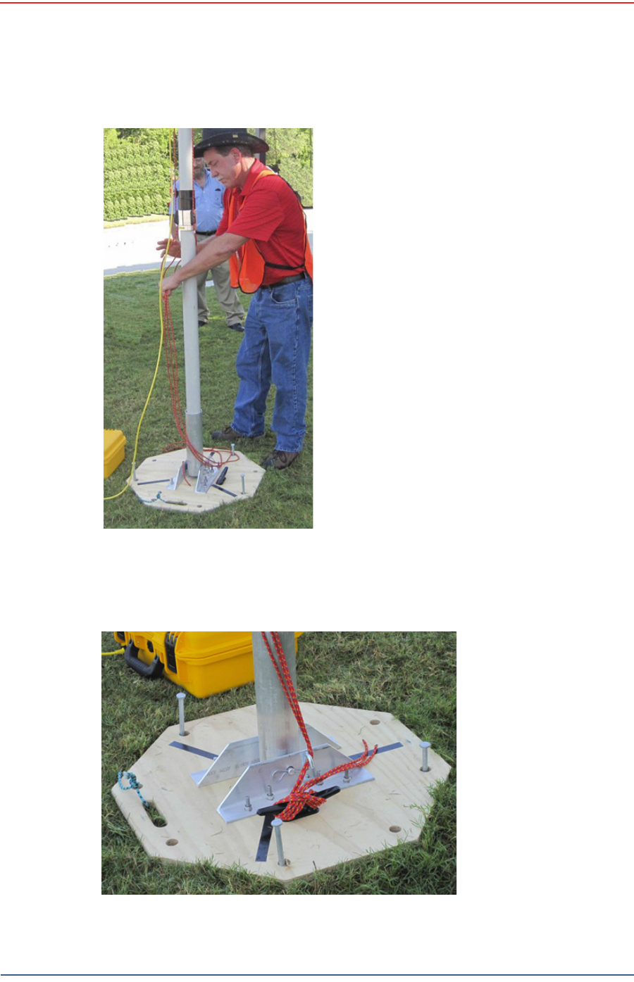
1 5 Secure the t wo lines t hat angle away from the line of t he m ast int o t he cleats
at t he m arks on t he rope. The t hird rope which is in line wit h t he m ast will be
secured aft er t he m ast is raised.
Figure 4 – 3 5 Guy Lin e Collar
Figure 4 – 3 6 Threa ding Guy Line s Through Clea t s

Draft
R03.d RT 1000 v1.3 Deploym ent Guide 63
© 2010- 2011 Wir eless Seism ic, I nc. All right s reserved.
Backhaul
Set t ing up t he Backhaul Equipm ent
1 6 While holding the free guy line, lift / walk the m ast t o a vertical posit ion and
secure t he line int o the cleat.
Figure 4 – 3 7 W a lk in g t he M a st t o Ve rt ica l 1
Figure 4 – 3 8 W a lk in g t he M a st t o Ve rt ica l 2

Draft
64 RT 1000 v1.3 Deploym ent Guide R03.d
© 2010- 2011 Wir eless Seism ic, I nc. All right s reserved.
Backhaul
Setting up the Backhaul Equipment
Figure 4 – 3 9 W alk ing t he M a st t o Ve r t ica l
3

Draft
R03.d RT 1000 v1.3 Deploym ent Guide 65
© 2010- 2011 Wir eless Seism ic, I nc. All right s reserved.
Backhaul
Set t ing up t he Backhaul Equipm ent
1 7 Adj ust all lines t o bring t he m ast t o a vertical posit ion.
1 8 Ensur e t hat each line is firm ly seat ed in each cleat, loosely wrap lines around
m ast and secure at t he large cleat on t he base.
Figu r e 4 – 4 0 Se cu r in g t h e Guy Lin e t o
t he Cleat

Draft
66 RT 1000 v1.3 Deploym ent Guide R03.d
© 2010- 2011 Wir eless Seism ic, I nc. All right s reserved.
Backhaul
Setting up the Backhaul Equipment
Figure 4 – 4 1 Tight ening Guy
Lin e s in Cle a t s
Draft
R03.d RT 1000 v1.3 Deploym ent Guide 67
© 2010- 2011 Wir eless Seism ic, I nc. All right s reserved.
Backhaul
Set t ing up t he Backhaul Equipm ent
Figu r e 4 – 4 2 W r apping Lines
Ar ound t he Ma st
Figure 4 – 4 3 Se cur in g Lin e s t o La r ge Cle a t

Draft
68 RT 1000 v1.3 Deploym ent Guide R03.d
© 2010- 2011 Wir eless Seism ic, I nc. All right s reserved.
Backhaul
Setting up the Backhaul Equipment
1 9 Check to m ake sure t hat the ant ennas are aim ed properly.
2 0 Uncoil an Et hernet cable. Att ach one end t o the BSU and t he ot her end t o the
PoE.
2 1 Check Ethernet stat us light s, if not green or flashing green rem ove Ethernet
cable from t he PoE, count t o five and re- insert.
2 2 I f stat us does not change t o green or flashing green report the condit ion.
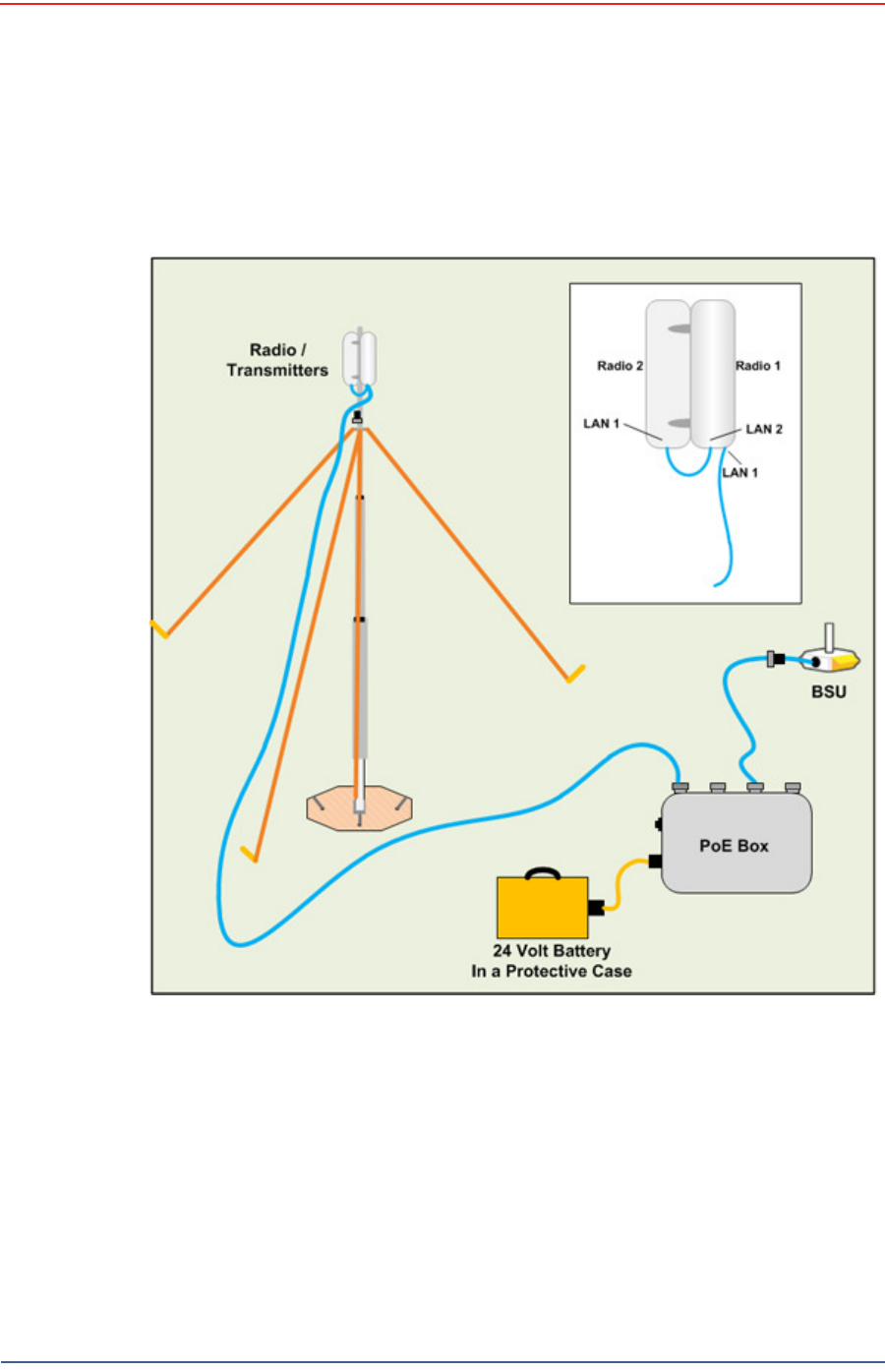
Figure 4 – 4 4 Ba ck haul Ant enna Ere ct ed
Draft
R03.d RT 1000 v1.3 Deploym ent Guide 69
© 2010- 2011 Wir eless Seism ic, I nc. All right s reserved.
Backhaul
I nstalling Two Radios on the Mast
4.5 Installing Two Radios on the Mast
When you are inst alling a rem ot e backhaul, t here can be t wo radios on t he m ast
as shown in t he following figure:
To in st a ll t w o radios on t he m ast :
1Prerequisit es:
●TBD
●The radios are configured to allow t he PoE opt ion ( see step 11 on page 56) .
●The radios are BOTH configured as m esh POI NTS ( see st ep 6 on page 54) .
2At t ach t wo radios t o t he m ast . Refer t o t he deploym ent instructions for the
locat ion at which to aim the radio. One should point t owards t he recording
Figure 4 – 4 5 Tw o- Ra dio I nst a lla t ion

Draft
70 RT 1000 v1.3 Deploym ent Guide R03.d
© 2010- 2011 Wir eless Seism ic, I nc. All right s reserved.
Backhaul
Removing the Backhaul Equipment
truck ( uplink) , and t he other should point t owards the next rem ote backhaul
locat ion ( downlink) .
3Connect t he t wo radios with a short Ethernet cable: Radio1/ LAN 2 t o Radio 2/
LAN 1.
4Connect Radio 1/ LAN 1 t o t he PoE.
4.6 Removing the Backhaul Equipment
TBD
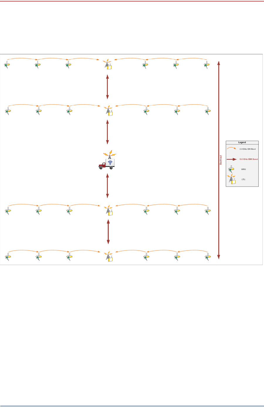
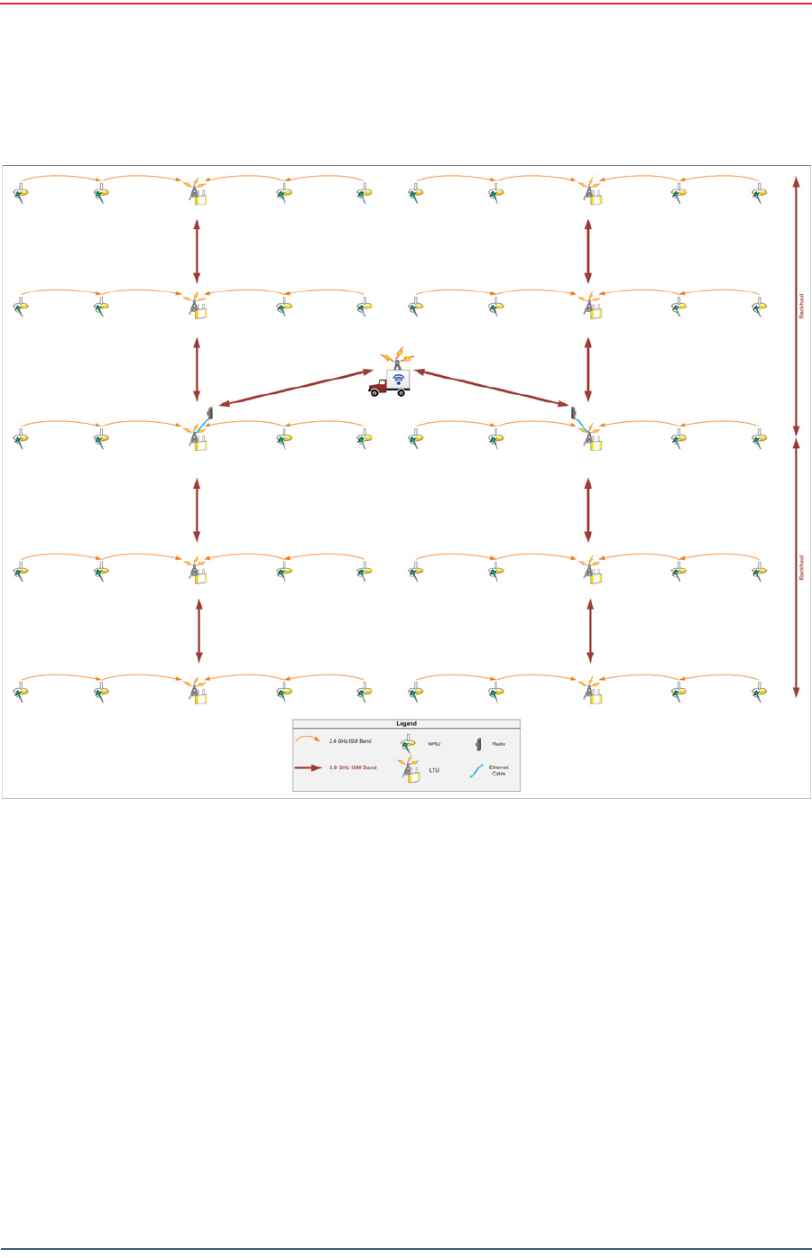
4.7 Use Cases or Example Deployments
This sect ion shows a few exam ple deploym ents.
Draft
R03.d RT 1000 v1.3 Deploym ent Guide 71
© 2010- 2011 Wir eless Seism ic, I nc. All right s reserved.
Backhaul
Use Cases or Exam ple Deploym ent s
Figure 4 – 4 6 2 D Single Ba ckha ul
Draft
72 RT 1000 v1.3 Deploym ent Guide R03.d
© 2010- 2011 Wir eless Seism ic, I nc. All right s reserved.
Backhaul
Use Cases or Example Deployments
Figu r e 4 – 4 7 3 D Dua l Ba ck haul, Tw o Root N odes
Draft
R03.d RT 1000 v1.3 Deploym ent Guide 73
© 2010- 2011 Wir eless Seism ic, I nc. All right s reserved.
Backhaul
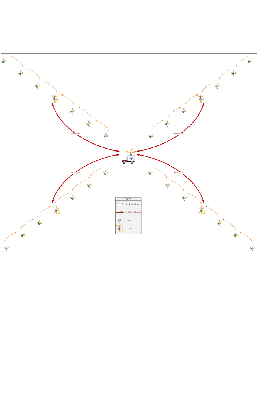
Use Cases or Exam ple Deploym ent s
Figure 4 – 4 8 2 D Single Ba ckhaul, St ar Configura t ion

Draft
RT 1000 v1.3 74 Deploym ent Guide R03.d
© 2010- 2011 Wir eless Seism ic, I nc. All right s reserved.
5
Demobilization
5.1 Overview
This chapt er describes how t o prepare (undeploy) t he ground electronics for
transport at the end of a proj ect ( dem obilization) .
5.2 Removing the WRU from the Field
This sect ion describes t he process t o ready t he WRU for m ovem ent t o a new
physical locat ion or t o rem ove it in preparat ion for dem obilization.
To un deploy t he W RU:
1Prerequisit es:
●The WRU is assem bled wit h bat t ery, geophone, and ant enna
●The WRU is in an act ive, t ransit ional, or ready stat e
2Pick up the WRU and point t he geophone connect or end t owards t he sky as
shown in the following figure. All of the LEDs illum inat e:
3Place t he unit flat in t he t ransportat ion vehicle as shown in t he follow ing
figure. The unit shut s down. The LEDs on the t op of the unit are off.
Figure 5 – 1 Pow e r Off t he
Un it

Draft
R03.d RT 1000 v1.3 Deploym ent Guide 75
© 2010- 2011 Wir eless Seism ic, I nc. All right s reserved.
Demobilization
Disassem ble t he WRU
4Opt ional: Rem ove batt eries, ant enna, or geophone as described in
“ Disassem ble t he WRU” on page 75.
5.3 Disassemble the WRU
This sect ion describes t he process t o disassem ble the WRU prior to dem obilization.
To disa sse m ble t h e W RU:
1Undeploy t he equipm ent as described in “ Rem oving t he WRU from the Field” on
page 74.
2Rem ove t he ant enna from t he unit using nylon grip pliers.
Figu r e 5 – 2 Unde ployed Unit
TBD
Figure 5 – 3 Re m oving t he Ant e nna
Draft
76 RT 1000 v1.3 Deploym ent Guide R03.d
© 2010- 2011 Wir eless Seism ic, I nc. All right s reserved.
Demobilization
Disassemble the WRU
3Rem ove t he geophone from t he unit .
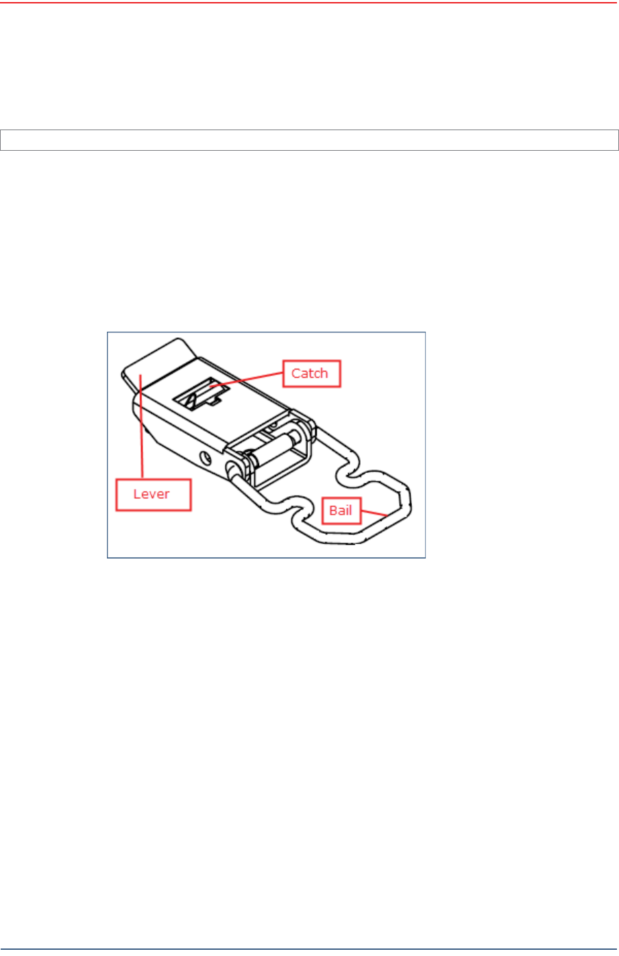
4Rem ove t he bat t eries from t he unit .
●Press the cat ch on t he bat t ery latch.
●Lift t he lever, but do not lift t he bail from t he m olded area on t he bat t ery.
●Continue t o lift the lever using t he bail t o push t he bat tery out of t he
connector.
5Secure the equipm ent in t he t ransport vehicle.
I m age showing geophone inst allation TBD.
Figure 5 – 4 Re m oving t h e Ge ophone
Figure 5 – 5 Rem oving the Ba t t er y

Draft
RT 1000 v1.3 77 Deploym ent Guide R03.d
© 2010- 2011 Wir eless Seism ic, I nc. All right s reserved.
6
Testing and Maintaining the
Equipment
6.1 Overview
This chapt er describes int ernal and ext ernal t ests for t he ground equipm ent .
6.2 Testing the Layout
TBD
6.2.1 Line Tests
TBD
6.2.2 Source Control Tests
TBD
6.2.3 Acquisition Parameter Testing
TBD
6.2.4 Built-In-Self-Test (BIST)
TBD
WARNING
I n or der t o com ply wit h FCC radio frequency (RF) exposure
requirem ent s, t he RT 1000 unit s m ust be inst alled so that a m inim um
separat ion dist ance of 20 cm is m aint ained bet ween the ant enna( s) and
all persons at all t im es during norm al operat ion.

Draft
78 RT 1000 v1.3 Deploym ent Guide R03.d
© 2010- 2011 Wir eless Seism ic, I nc. All right s reserved.
Testing and Maintaining the Equipment
Maintaining the Equipment
6.3 Maintaining the Equipment
TBD
6.3.1 Units
TBD
6.3.2 Antennas
TBD
6.3.3 Geophones
TBD
6.3.4 Cautions
TBD

Draft
RT 1000 v1.3 79 Deploym ent Guide R03.d
© 2010- 2011 Wir eless Seism ic, I nc. All right s reserved.
7
Troubleshooting and Tips
7.1 Best Practices
This sect ion provides som e t ips on wor king w ith t he equipm ent .
7.1.1 24 Ah Batteries
I n or der t o m aint ain t he best possible com m unication channel, observe the
following t ips:
Place a fully char ged 24 Ah bat t ery on t he backhaul ever y day.
Keep ext ra 24 Ah bat t eries charged up at the st aging area.
St ore 24 Ah bat t eries at the st aging area when not in use. Deep
discharging of t he bat t eries can short en t heir lifespan considerably.
7.1.2 Fluidmesh Radios
I f you are having t rouble com m unicat ing with t he Fluidm esh radios, check t he
following:
Try sending a ping com m and in a CMD window t o t he I P address of t he
radio.
I f you are t rying to connect direct ly wit h a com puter, m ake sure you have
configured a privat e net work (see “ Create a Privat e Network” on page 43) .
Ensure t hat you have configured t he radios as follows:
●FM1100 = m esh POI NT (rem ote backhaul)
●FM3100 = m esh END ( cent ral backhaul)
I t t akes one full m inut e t o see t he alignm ent stat istics in the Fluidm esh GUI
( from the browser) , so be sure to wait for it .
NOTE
I f you configure t wo FM1100 radios on t he sam e m ast t o be a m esh
POI NT and a m esh END, t hey will com m unicate over t he sw itch and lock
ever yt hing else out of t he com m unicat ion loop. They m ust bot h be
configur ed as m esh POI NTs.

Draft
80 RT 1000 v1.3 Deploym ent Guide R03.d
© 2010- 2011 Wir eless Seism ic, I nc. All right s reserved.
Troubleshooting and Tips
Best Practices
7.1.3 PoE
When t em perat ure swings are ext rem e, or weat her is severe, st ore t he PoE boxes
in t he recording t ruck at night .
To ensure a prot ect ed connect ion, be sure to use an Ethernet cable with a
protective shell ( 65- 0051) when connecting Ethernet cables to the PoE ( see Figure
4–8 Prot ect ive Et hernet Connector on page 34) .
7.1.4 Urban Environments
The following could im pact your configuration in urban environm ent s:
You m ay need t o use repeaters when crossing a road.
You m ay need t o adj ust WRU placem ent and ant enna st rength when crossing a
road.
You will need t o consider t he presence of pow er lines and buildings when
placing WRUs and backhaul com ponents.
7.1.5 Ethernet Cables
Use CAT6 qualit y cables.
To ensure a prot ect ed connect ion, be sure to use an Ethernet cable with a
protective shell ( 65- 0051) when connecting Ethernet cables to the PoE ( see Figure
4–8 Prot ect ive Et hernet Connector on page 34) .
7.1.6 Antennas
When placing or select ing antennas in, consider t he follow ing:
I n areas where t here is a st eep inclinat ion, sm aller gain ant ennas m ay provide
a bet t er signal.
I n areas wher e t here is a st eep inclinat ion, t ry t o reduce t he inclination by
going up or dow n at an angle rat her t han straight up or down.
Use repeaters to cover overpass and steep inclinat ion sit uat ions.
I f you need m ore signal strengt h, use an ext ender wit h a riser t o elevate t he
ant enna.
CAUTION
Do not allow t he PoE batt ery t o rem ain connected at a voltage of 22V or
less. Dam age t o t he equipm ent could occur.

Draft
RT 1000 v1.3 81 Deploym ent Guide R03.d
© 2010- 2011 Wir eless Seism ic, I nc. All right s reserved.
8
Batteries
This chapt er provides inform ation about t he bat teries and bat t ery
requirem ent s.
8.1 Lithium Ion Battery Specifications
The RT 1000 uses one or t wo custom int elligent lit hium - ion bat teries w ith self-
cont ained charging circuitry t hat protect s the bat t eries from overcharge,
discharge, short circuits, or extrem e t em perat ure charging.
Bat t ery specifications are shown in the following table:
Table 8 – 1 Lit h ium I on Bat t e ry Spe cificat ion s
Volt age Nom inal 3.7 VDC
Sh ut - off 2.8 VDC
Full ( 90% ) charge 4.1 VDC
Full ( 90% ) charge
m Ah
Approxim ately 12,000
m Ah at nom inal voltage
Full ( 90% ) charge
m Wh
Approxim ately 44,400
m Wh at nom inal volt age
Connect or 5 - pin
LED One LED t hat indicat es
charging st at us when
connected t o t he
charging st at ion as
follows
●Green – Charged
●Red – Charging
●Am ber –
Transit ional phase
bet ween charging
and charged, or
charge
tem perature
lim it s exceeded
Label One bar code serial
num ber label

Draft
82 RT 1000 v1.3 Deploym ent Guide R03.d
© 2010- 2011 Wir eless Seism ic, I nc. All right s reserved.
Batteries
Lithium Ion Battery Charger
8.2 Lithium Ion Battery Charger
The lit hium ion bat t ery charger is designed t o operat e from a single 10 A, 120 VAC
service line.
Tem perat ure Operat ing From - 50° C to + 75° C
Charging From 0°Cto+45°C
Am bient St orage ►From - 20° C t o
+ 45° C for a
m axim um
period of one
m ont h
►From - 20° C t o
+ 35° C for a
m axim um of 6
m ont hs, aft er
which t im e
the batt ery
packs will
need t o be
rechar ged t o
above 50%
capacity
Table 8 – 1 Lit h ium I on Bat t e ry Spe cificat ion s
Draft
R03.d RT 1000 v1.3 Deploym ent Guide 83
© 2010- 2011 Wir eless Seism ic, I nc. All right s reserved.
Batteries
Lit hium I on Bat tery Charger
The power supply t o charge t he bat tery pack is a 5VDC regulat ed voltage supply.
Figure 8 – 1 Ba t t e ry Char ger

Draft
84 RT 1000 v1.3 Deploym ent Guide R03.d
© 2010- 2011 Wir eless Seism ic, I nc. All right s reserved.
Batteries
BSU Battery
8.3 BSU Battery
TBD
Figu r e 8 – 2 Seria l N um be r
La be l a n d LED I ndicat or

Draft
RT 1000 v1.3 85 Deploym ent Guide R03.d
© 2010- 2011 Wir eless Seism ic, I nc. All right s reserved.
A
Legal Information
A.1 FCC Rules and Regulations Compliance
The Federal Com m unicat ions Com m ission ( FCC) regulates t he use of antennas
in t he “ Code of Federal Regulat ions – Tit le 47, Part 15 – Radio Frequency
Devices, Subpart C – I nt ent ional Radiators, Sect ion 15.203 Antenna
Requirem ent .”
When used as int ended, the RT 1000 com plies wit h FCC Section 15.203
requirem ent s as follow s:
The RT 1000 antennas shall be installed and handled by professionals
specifically designat ed for t his purpose.
Changes or m odificat ions not expressly approved by Wireless Seism ic, I nc.
can void t he users’s aut hority t o operat e t he equipm ent.
The RT 1000 shall be used wit h only t he supplied ant ennas (Table A–1)
at t ached t o t he WRU or BSU wit h an integrat ed t ype N m ale connector.
NOTE
This equipm ent has been t ested and found t o com ply wit h t he lim it s for
a Class A digital device, pursuant to part 15 of t he FCC Rules. These
lim it s are designed t o provide reasonable protection against harm ful
int erference when t he equipm ent is operated in a com m ercial
environm ent. This equipm ent generates, uses, and can radiat e radio
frequency energy and, if not inst alled and used in accordance w ith t he
inst ruction m anual, m ay cause harm ful int erference t o radio
com m unications. Operat ion of this equipm ent in a r esidential area is
likely t o cause har m ful int er fer ence in which case t he user w ill be
required t o correct t he int erference at his own expense.
Table A– 1 An t e n n a Spe cifica t ions
Mode l Fr eque n cy
( MH z) Gain Vert ical
Bandw idt h W eight
Dim ension
( Le n gt h x
D ia m e t e r )
WSI 65- 0067 2400- 2485 9 dbi 14° 0.8 lbs
0.5 kg
27 x 0.6 in
690 x 15 m m
WSI 6060- 001- 01 24 00 - 24 85 7 dBi 18° 0.6 lbs
0.3 kg
21 x 0.6 in
540 x 15 m m

Draft
86 RT 1000 v1.3 Deploym ent Guide R03.d
© 2010- 2011 Wir eless Seism ic, I nc. All right s reserved.
Legal Information
FCC Rules and Regulations Compliance
The Base St at ion Unit has been grant ed FCC equipm ent aut horizat ion under t he
FCC I dentifier YZO-00400.
The Wireless Rem ote Unit has been grant ed FCC equipm ent aut horization under
the FCC I dent ifier YZO- 00100.
WSI 65- 0023 2400- 2485 5 dBi 25º 0.5 lbs
0.2 kg
12 x 0.6 in
355 x 15 m m
WSI 65- 0025 2400-2485 2 dBi @ 2.4 120° 1.6 oz
45.4 g
7.6 x 0.5 in
193 x 12.7 m m
Table A– 1 An t e nna Specifica t ions ( cont .)
Mode l Fr eque n cy
( MH z) Gain Vert ical
Bandw idt h W eight
Dim ension
( Le n gt h x
D ia m e t e r )
WARNING
I n or der t o com ply wit h FCC radio frequency (RF) exposure
requirem ent s, t he RT 1000 unit s m ust be inst alled so that a m inim um
separat ion dist ance of 20 cm is m aint ained bet ween the ant enna( s) and
all persons at all t im es during norm al operat ion.

Draft
RT 1000 v1.3 87 Deploym ent Guide R03.d
© 2010- 2011 Wir eless Seism ic, I nc. All right s reserved.
B
Fluidmesh Radio Specifications
The inform at ion in this chapt er is repr oduced here for your convenience from
the Fluidm esh dat a sheet available at t he following locat ion:
ht t p: / / ww w.fluidm esh.com / press- room / product- literature/ doc_det ails/ 160-
flu id m esh - m it o- series
© 2005- 2010 Fluidm esh Net works, I nc.
B.1 The Fluidmesh Mito Series
The Fluidm esh® MI TO Series is a MI MO- based tri- band wir eless Ethernet
product line designed and m anufact ured specifically for m ult i- service backhaul
applicat ions.
MI TO - The Revolut ion in W irele ss Ba ckhauling
Wit h t he MI TO product line, Fluidm esh has developed a revolut ionary wireless
backhaul solution t hat is capable of offering extrem e perform ances with a
sm all form fact or. MI TO is a unique 2x2 MI MO solut ion wit h int egrat ed
directional ant ennas which has allow ed Fluidm esh t o break t he m ould and
creat e a product line t hat is a gam e changer in the w ireless backhauling arena.
You won't need t o inst all ext ernal antennas. You won't need to deal with
coaxial cables, light ing suppressors, and grounding. The Fluidm esh
1100 MI TO and t he Fluidm esh 3100 MI TO have an int egrat ed radio-ant enna
solut ion wit h an out door rat ed enclosure that is slightly bigger t han t wo decks
of cards. The Fluidm esh 11oo MI TO m ount s a 2x2 MI MO pat ch ant enna and
can be used to creat e point to point, point t o m ult ipoint, and m esh net works
providing unparalleled perform ances and a com pact form factor. The Fluidm esh
3100 MI TO m ount s a 2x2 MI MO sector antenna and is designed for m edium
and large point t o m ult ipoint deploym ents with up t o 150 client s.
Tri- ba nd Radio oper a t ing a t 4 .9 GH z, and 5 .1 - 5 .8 GH z
The Fluidm esh MI TO Series features one tri- band radio and can operat e at 4.9
GHz, and 5.1- 5.8 GHz and m odulat e up to 300 Mbps. The preferred frequency
can be easily select ed through a web based int erface.
Opt im ize d Prodigy Tra n sm ission Prot ocol for m ax im u m Re lia bilit y
The Fluidm esh MI TO Series em ploys Prodigy, Fluidm esh's proprietary high
perform ance 'int elligent ' transm ission prot ocol, built to overcom e t he lim it s of
st andard license- free protocols and t o deliver a wireless infrast ructure with a
higher level of r eliability. Pr odigy was developed t o transm it any I P- com patible

Draft
88 RT 1000 v1.3 Deploym ent Guide R03.d
© 2010- 2011 Wir eless Seism ic, I nc. All right s reserved.
Fluidmesh Radio Specifications
The Fluidmesh Mito Series
traffic including data, video, and voice. At t he base of our innovat ive t ransm ission
protocol, t here is a t raffic optim izat ion algorit hm t hat allows every Fluidm esh
device to assign a specific level of priority and reliabilit y t o every packet
transm it t ed. This process allows the w ireless net work to aut om at ically adj ust its
transm ission param et er s based on t he t ype of t raffic t ransm itt ed. The overall
result is a bet t er, m ore reliable, m ult i- service wireless infrast ruct ure.
Com pa ct De sign for Easy I nst allat ion
The Fluidm esh MI TO Series has a com pact form factor designed for low visual
im pact deploym ent s. The integrat ed panel antenna m akes for easy inst allation and
support s a range of up t o 30 m iles in line of sight . The provided low- power POE
inj ector guarant ees a straight- forward set - up.
Flu ldTh r ot t le ™
The Fluidm esh MI TO Series is based on the innovat ive FluidThrot t le™ technology
which allows t he user t o lim it t he t ot al cost of ownership of the w ireless network
by paying only for t he am ount of bandwidth required. Additional t hroughput can be
easily achieved by upgrading t he system wit h soft ware plug- ins in case the
bandwidt h requirem ents increase over t im e. This solut ion m akes Fluidm esh the
m ost cost- effect ive and flexible wir eless solut ion provider in t he m arket .
FluidMAX™
The Fluidm esh MI TO Series support s t he patent- pending FluidMAX™ t echnology
and can be used t o create Point- to-Point, Point- t o- Multipoint , and Mesh
archit ect ures. Thanks t o FluidMAX™, the Fluidm esh MI TO Series can operat e wit h
a cent ralized m edium access cont rol protocol, or with a distribut ed m edium access
cont rol prot ocol, depending on the net work layout . That m eans t hat our unit s can
operate in eit her CSMA or TDMA. The decision is m ade aut om atically by t he
net work based on its layout and requires no user int ervent ion.
Ea sy M esh® Pla t for m a n d FM Quadr o I nt erface
The Fluidm esh MI TO Series includes EasyMesh™. The EasyMesh t echnology allows
the user t o set t he sam e range of private I P addresses across t he ent ire network.
The Fluidm esh MI TO Series also includes t he FMQuadro™ web int erface w hich
allows the user t o configure, m onit or, and t roubleshoot t he w ireless network in real
tim e wit hout t he need of addit ional soft ware or a server. The unit com es wit h a
built- in spect rum analyzer, a real- tim e bandwidt h m onit oring t ool, and a w izard t o
facilit ate t he configurat ion of t he syst em .
AES- 1 2 8 Encrypt ion Support ( FI PS- 1 9 7 Com plia n t )
The Fluidm esh MI TO Series includes support for 128 bit AES Encrypt ion at t he link-
level which can be used for FI PS- 197 com pliance. Because AES I s I m plem ent ed in
hardware, t here is no loss in t erm s of perform ance w hen AES is enabled.
Sim ple N et w ork M a nage m ent Pr ot ocol ( SN M P) Suppor t
The Fluidm esh MI TO Series support s SNMP version 3. The Sim ple Net work
Managem ent Prot ocol allows t he user to centrally m anage t he m esh devices wit h a
SNMP server and t o receive autom atic alarm s in case of net w or k failure.

Draft
R03.d RT 1000 v1.3 Deploym ent Guide 89
© 2010- 2011 Wir eless Seism ic, I nc. All right s reserved.
Fluidmesh Radio Specifications
Fluidm esh 1100 with MI TO Technology
B.2 Fluidmesh 1100 with MITO Technology
RAD I O
ELECTRI CAL
EN V I RO N MEN TAL
PHYSI CAL
Frequency Bands: 5.15- 5.25 and 5.725- 5.825 GHz ( US, FCC)
5.470- 5.725 GHz (Europe, ETSI )
4.940 - 4.990 GHz ( US,FCC)
Modulat ion: OFDM ( BPSK, QPSK, 16- QAM, 64- QAM)
Modulat ion speed: Up t o 300 Mbps
TX Power: Up t o 27 dBm , depending on configuration and
regulat ory const raints
AX Sensitivity 5GHz: - 96d8@6.5Mbps; - 75dB@300Mbps
Ant enna Type: 2x2 MI MO
Ant enna Gain: 14.6- 16.1 dBi
Ant enna Polarizat ion: Dual Linear
Cross- pol I solat ion: 22dB m inim um
Max VSWR: 1.6: 1
H- pol Beam width: 43 deg.
V-pol Beam widt h: 41 deg.
Elevat ion Beam widt h: 15 deg.
Power in put : Passive PoE 15V
DC,
0.8A, (pairs
4,5+;
7,8
return
)
Power
consum ption:
Max
8W
Power over E
ther net
I n j ect or :
Included
,
90/260V
50/60 Hz AC
input
Operating Tem perat ure: - 30° C to + 80° C
St orage Tem perat ure: - 30° C to + 80° C
Hum idity: 95% condensing
Weat her Rat ing: I P65
Wind Survivability: 120 m ph
Shock & Vibrat ion: ETSI 300- 019- 1.4
I nt erfaces: Two ( 2) I nt ernal Et hernet
10/ 100BaseT aut osensing, RJ45
Dim ensions ( m m ) : 294 ( h) X 80 ( w) X 30( d)
Wei g h t ( Kg) : 0 . 4
Enclosure m at erial: Out door UV St abilized Plastic

Draft
90 RT 1000 v1.3 Deploym ent Guide R03.d
© 2010- 2011 Wir eless Seism ic, I nc. All right s reserved.
Fluidmesh Radio Specifications
Fluidmesh 3100 with MITO Technology
OPTI ON AL SOFTW ARE PLUG- I N S
Ethernet Capacit y Plug-in up t o 1 Mbps ( included)
Ethernet Capacit y Plug-in up to 2.5 Mbps
Ethernet Capacit y Plug-in up to 5 Mbps
Ethernet Capacity Plug- in up t o 10 Mbps
Ethernet Capacity Plug- in up t o 30 Mbps
Ethernet Capacity Plug- in up t o 60 Mbps
Unlim ited Wired Ethernet Capacit y Plug- in ( up t o 100 Mbps)
802.1Q VLAN Support
AES-128 Encrypt ion
B.3 Fluidmesh 3100 with MITO Technology
RAD I O
ELECTRI CAL
EN V I RO N MEN TAL
Frequency Bands: 5.15- 5.25 and 5.725- 5.825 GHz ( US, FCC)
5.470- 5.725 GHz (Europe, ETSI )
4.940 - 4.990 GHz ( US,FCC)
Modulat ion: OFDM ( BPSK, QPSK, 16- QAM, 64- QAM)
Modulat ion speed: Up t o 300 Mbps
TX Power: Up t o 27 dBm , depending on configuration and
regulat ory const raints
AX Sensitivity 5GHz: - 96d8@6.5Mbps; - 75dB@300Mbps
Ant enna Type: 2x2 MI MO
Ant enna Gain: 14.6- 17.1 dBi
Ant enna Polarizat ion: Dual Linear
Cross- pol I solat ion: 22dB m inim um
Max VSWR: 1.5: 1
H- pol Beam width: 72 deg.
V-pol Beam widt h: 93 deg.
Elevat ion Beam widt h: 8 deg.
Power in put : Passive PoE 24V
DC,
1A, (pairs
4,5+;
7,8
return
)
Power
consum ption:
Max
8W
Power over E
ther net
I n j ect or :
Included
,
90/260V
50/60 Hz AC
input
Operating Tem perat ure: - 30° C to + 75° C

Draft
R03.d RT 1000 v1.3 Deploym ent Guide 91
© 2010- 2011 Wir eless Seism ic, I nc. All right s reserved.
Fluidmesh Radio Specifications
MI TO Ser ies General Charact er istics
PHYSI CAL
OPTI ON AL SOFTW ARE PLUG- I N S
Ethernet Capacit y Plug-in up t o 10 Mbps
Ethernet Capacit y Plug-in up t o 30 Mbps
Ethernet Capacit y Plug-in up t o 60 Mbps
Unlim ited Wired Ethernet Capacity Plug- in ( up t o 100 Mbps)
802.1Q VLAN Support
AES- 128 Encryption
B.4 MITO Series General Characteristics
N ETW ORK
Prot ocols: UDP, TCP, I P, RTP, RTCP, RTSP, HTI P, HTI PS, I CMP, ARP
Medium Access Cont rol ( MAC) Protocols: Centralized Polling-based, Distribut ed
CSMA/ CA- based
Web-based int erface for rem ot e m anagem ent
Multicast support
UPnP support
NMP support
802.1Q VLAN Support
SECURI TY
Full VPN com pat ibility
Full com pat ibilit y wit h all encr ypt ion and aut hent ication standards
( AES, 3DES, RSA, HTI PS, SSL, et c.)
AES-128 ( FIPS- 197 Com pliant) Link- level Encrypt ion
APPROVALS
FCC CFR 47 Part 15, class B
I ndustry Canada RSS 210
St orage Tem perat ure: - 30° C to + 75° C
Hum idity: 95% condensing
Weat her Rat ing: I P65
Wind Survivability: 120 m ph
Shock & Vibrat ion: ETSI 300- 019- 1.4
I nt erfaces: One ( 1) I nt ernal Et hernet
10/ 100BaseT aut osensing, RJ45
Dim ensions ( m m ) : 370 ( h) X 80 ( w) X 70( d)
Wei g h t ( Kg) : 1 . 6
Enclosure m at erial: Anodized Alum inum

Draft
92 RT 1000 v1.3 Deploym ent Guide R03.d
© 2010- 2011 Wir eless Seism ic, I nc. All right s reserved.
Fluidmesh Radio Specifications
MITO Series General Characteristics
CEI !
SUPPLI ED ACCESSORI ES
PoE I nj ect or wit h US/ EU/ UK Power Cord
Pole Mount ing Kit ( i.e.Pole Mount ing Kit Max O.D. 2 in.)
W ARRAN TY
Two ( 2) years on par t s and labor
Three ( 3) years opt ional ext ended warrant y plan wit h advanced replacem ent
Five ( 5) year s opt ional extended warrant y plan wit h advanced replacem ent
Copyright
©
2005- 2010 Fluidm esh Net w orks, I nc. All rights reserved. Fluidm esh is
a registered t radem ar k of Fluidm esh Net works, I nc. EasyMesh, FMQuadro,
FluidMAX and FluidThrott le are t radem arks of Fluidm esh Networks, I nc. All ot her
brand or product nam es are t he t radem arks or registered t radem ar k of their
respect ive holder( s) . I nform at ion contained herein is subj ect to change wit hout
not ice. The only warrant ies for Fluidm esh Net works pr oduct s and services are set
forth in t he express warrant y st atem ents accom panying such product s and
services. Not hing herein should be construed as constit ut ing an addit ional
warranty. Fluidm esh Net works shall not be liable lor t echnical or edit orial errors or
om issions cont ained herein.
Fluidm esh Networks, I nc.
18 Trem ont Street , Suit e 730
Bost on, MA 02108
U.S.A.
Tel. + 1 { 617) 209- 6080
Fax. + 1 { 866} 458- 1522
ww w.fluidm esh.com
info@fluidm esh.com
EMEA Headquart ers { I taly}
Tel. + 39.02.0061.6189
UK Branch
Tel. + 44.2078.553.132

Draft
RT 1000 v1.3 93 Deploym ent Guide R03.d
© 2010- 2011 Wir eless Seism ic, I nc. All right s reserved.
C
LED Indicators
This chapt er provides t he possible LED stat us and error indicator s for WRUs
and BSUs.
Table C– 1 W RU LED St a t us I ndicat ions
LED I ndicat or s Sum m a r y D e scr ip t io n
Undeployed No light s are on; t he unit is undeployed.
Geo Dow n Tilt Det ected All LEDs are on solid
Bat tery t est in progress Flashing:
• MODE
• BAT
Bat tery A in use A flashing

Draft
94 RT 1000 v1.3 Deploym ent Guide R03.d
© 2010- 2011 Wir eless Seism ic, I nc. All right s reserved.
LED Indicators
Self t est in progress Flashing:
• MODE
• BAT
• GEO
• GPS
• RAD
Geophone t est in
pr ogress
Flashing:
• MODE
• GEO
Acquiring GPS fix Flashing:
• MODE
• GPS
Neighbor discovery in
pr ogress
Flashing:
• MODE
• RAD
Neighbor discovered Flashing:
• A
• MODE
• B
Cont inue ( lay flat t o
m ove t o next t est)
Solid:
• MODE
• GEO
• GPS
N OTE: To skip a t est dur ing t he self- test
pr ocess, t ilt t he unit vertical
(geophone down) until you see t his
triangle of LEDs. Tilt t he unit back t o
horizont al t o cont inue.
Table C– 1 W RU LED St at us I ndica t ions ( cont .)
LED I ndicat or s Sum m a r y D e scr ip t io n

Draft
R03.d RT 1000 v1.3 Deploym ent Guide 95
© 2010- 2011 Wir eless Seism ic, I nc. All right s reserved.
LED Indicators
Error LEDs rem ain persist ent throughout the self-discover y process and are t urned
off upon com plet ion. I f cert ain self-t est s fail, it is possible that t he WRU will power
down.
Sleeping RAD flashing
Table C– 1 W RU LED St a t us I ndica t ion s ( cont .)
LED I ndicat or s Sum m a r y D e scr ip t io n
Table C– 2 W RU LED Error I ndicat ions
LED I ndicat or s Sum m ary De scr ipt io n
Single batt ery failure
( B)
A flashing
Solid:
• B
• BAT
Single batt ery failure
( A)
B flashing
Solid:
• A
• BAT
Both batt eries failure Solid:
• A
• B
• BAT
Self t est failure Solid:
• BAT
• GEO
• GPS
• RAD

Draft
96 RT 1000 v1.3 Deploym ent Guide R03.d
© 2010- 2011 Wir eless Seism ic, I nc. All right s reserved.
LED Indicators
Geophone failure GEO solid
No GPS fix GPS solid
GPS fix within 10 m wit hin 1 m in not found
No neighbor det ected RAD solid
I f this is t he first WRU deployed, t his is t he
expected condition.
Table C– 2 W RU LED Error I ndica t ions ( cont .)
LED I ndicat or s Sum m ary De scr ipt io n
Table C– 3 BSU LED D iscipline I ndica t ions
LED I ndicat or s Sum m ary De scr ipt io n
Disciplining t o radio Flashing:
• A
• RAD
Disciplining t o GPS Flashing:
• A
• GPS

Draft
R03.d RT 1000 v1.3 Deploym ent Guide 97
© 2010- 2011 Wir eless Seism ic, I nc. All right s reserved.
LED Indicators
Disciplining A flashing
Disciplined to radio Flashing:
• B
• RAD
Disciplined to GPS Flashing:
• B
• GPS
Disciplined B flashing
I ncorrect ly dropped out
of cycle m ode
Flashing:
• A
• B
• BAT
• RAD
Arm ed MODE flashing
Table C– 3 BSU LED D iscipline I ndicat ions ( cont .)
LED I ndicat or s Sum m ary De scr ipt io n

Draft
RT 1000 v1.3 98 Deploym ent Guide R03.d
© 2010- 2011 Wir eless Seism ic, I nc. All right s reserved.
D
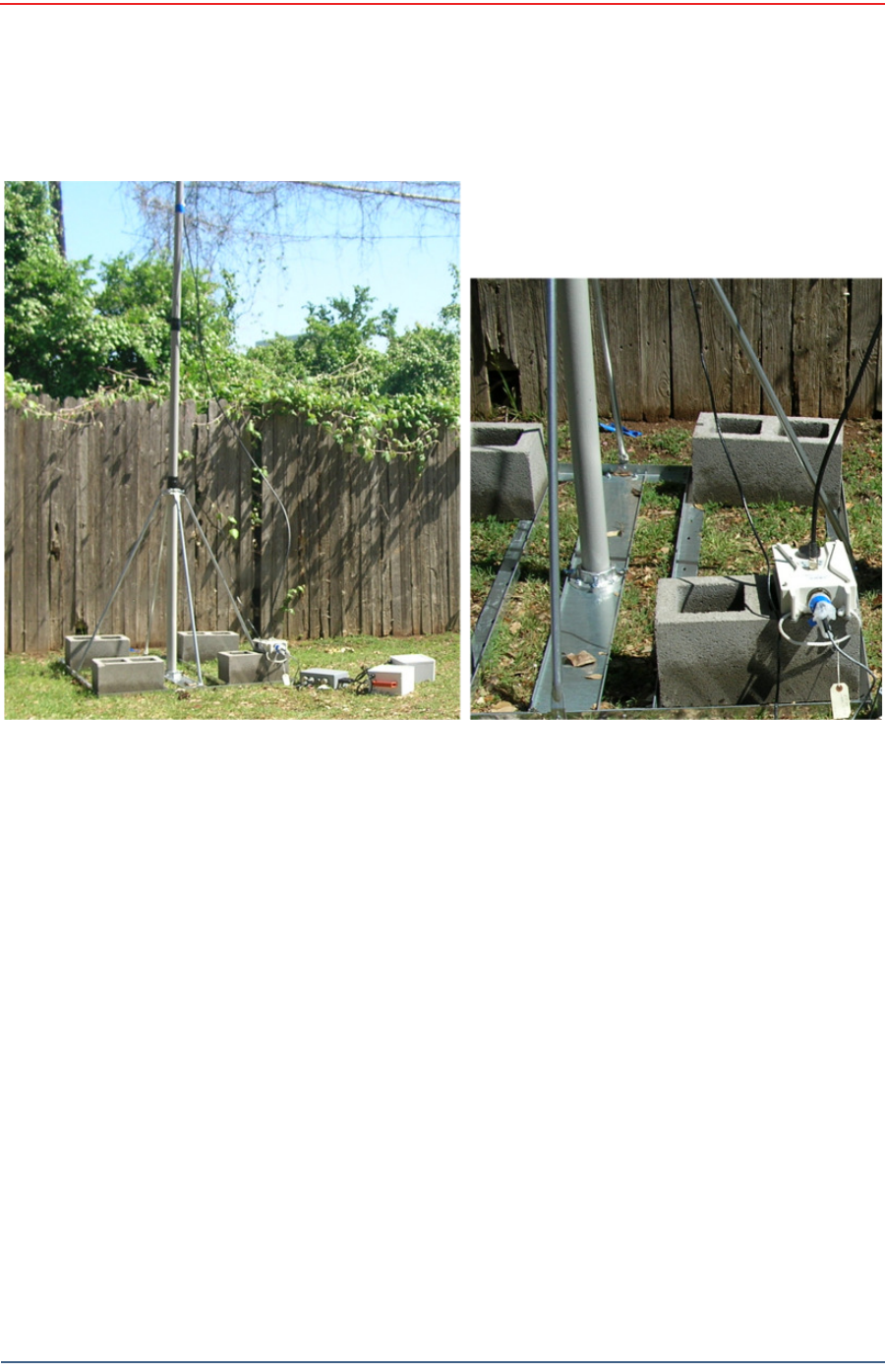
Weighted Mast
This sect ion describes t he m ast t hat uses w eight s t o m aint ain st ability.
D.1 Specifications
Tripod Weight = 50 lbs ( 22.73 kg)
Minim um m ast height = 53” ( includes 6” for m ount ing)
Base size = 48” ( 1.2m ) x 48” ( 1.2m )
Support s up to 12 – 16” x 8” blocks
Pre-galvanized steel fram e
Accept s up to 2.5” m ast ( not included)
Draft
R03.d RT 1000 v1.3 Deploym ent Guide 99
© 2010- 2011 Wir eless Seism ic, I nc. All right s reserved.
Weighted Mast
Hardware Supplied
D.2 Hardware Supplied
The following hardware is supplied wit h t he t ripod m ast:
4 - Bolt , Carriage 1/ 4 - 20 x 3/ 4"
12 - Bolt , Carriage 1/ 4 - 20 x 5/ 8"
4 - Bolt , 1/ 4 - 20 x 3/ 4" Hex Head
4- Bolt , 1/ 4 - 20 x 1/ 2" Hex Head
24- Nut, 1/ 4 - 20
24 - Lock washer, 1/ 4 I nt . t oot h
Figu r e D– 1 W eight ed Ma st
Draft
100 RT 1000 v1.3 Deploym ent Guide R03.d
© 2010- 2011 Wir eless Seism ic, I nc. All right s reserved.
Weighted Mast
Assembly Instructions
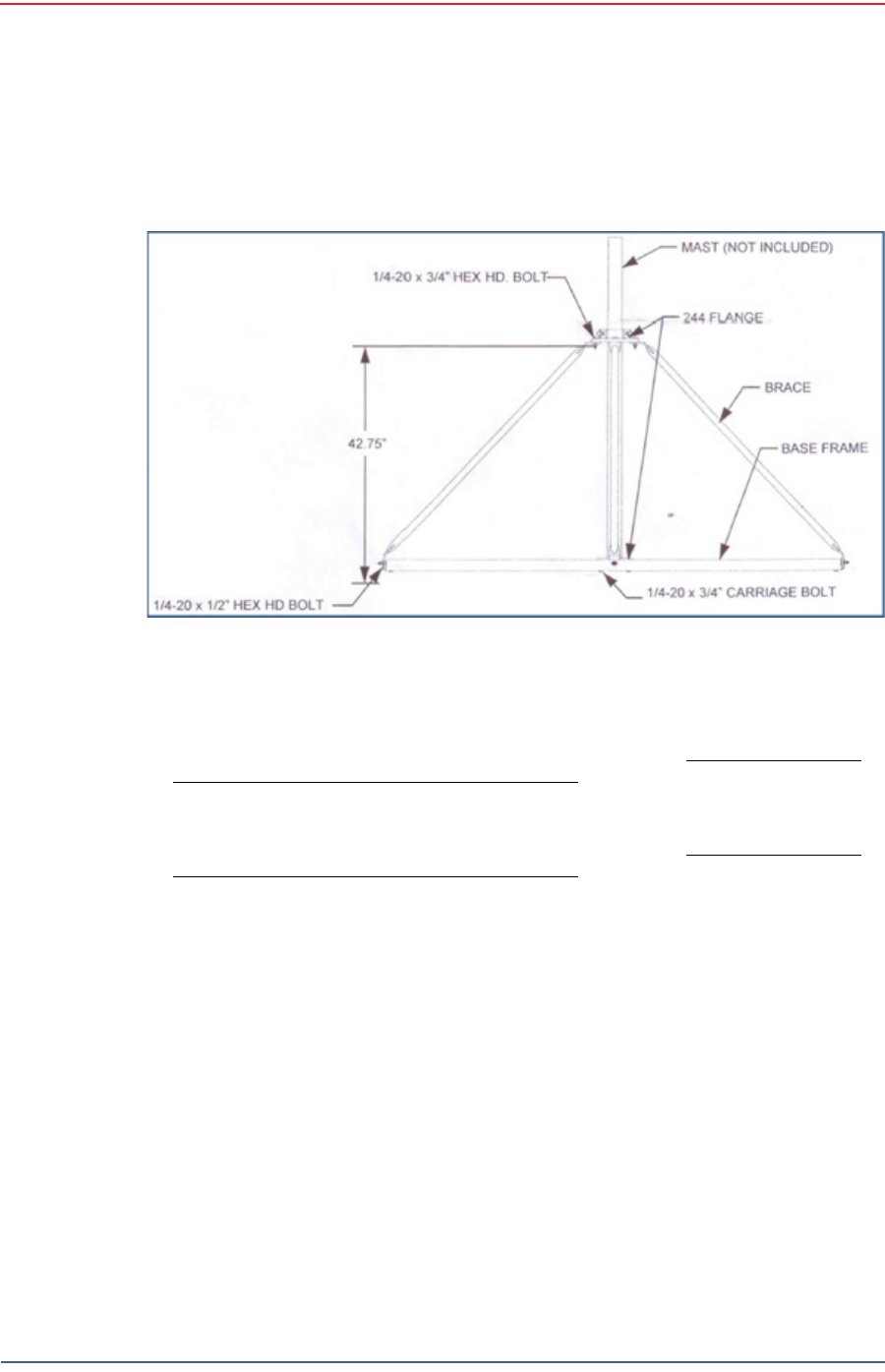
D.3 Assembly Instructions
This sect ion provides inst ruct ions and illustrat ions for assem bly of t he t ripod.
To assem ble t he t ripod:
1Assem ble one 244 Flange t o t he Center Support Plat e using four 1/ 4-20 x 3/ 4"
carriage Bolt s, Lock washers and Hex Nuts. Make sure to assem ble the Bolt s
wit h the Heads on the underside of t he fram e. Hex Nut should be on t he t op
side of the fram e.
2 Assem ble Base Fram e and Center Support Plat e using t w elve 1/ 4- 20 x 5/ 8"
carriage Bolt s, Lock washers and Hex Nuts. Make sure to assem ble the Bolt s
wit h the Heads on the underside of t he fram e. Hex Nut should be on t he t op
side of the fram e.
3Assem ble t he four ( 4) Braces to the upper support flange using four 1/ 4- 20x3/
4 Hex Head Bolt s, Lock washers and Nut s.
4Assem ble the other end of t he braces t o the base fram e using the four ( 4) 1/ 4-
20 x 1/ 2" Hex Head Bolts, Lock washer s, and Nuts.
5I nsert Bolt s int o upper and lower flange.
6Slide t he m ast ( not included) int o position and tighten securely and w eigh.
Wade An t en n a Lt d .
Ont ario, Canada
Figure D – 2 Tripod Asse m bly – Fron t View

Draft
RT 1000 v1.3 101 Deploym ent Guide R03.d
© 2010- 2011 Wir eless Seism ic, I nc. All right s reserved.
Index
A
ant e nna
specificat ions 35, 85
ant e nna s 85
B
backh a ul m a st s 39
C
con t act 9
F
FCC 85
Section 15.203 85
H
he lp 9
M
m o dif ica t ion s 85
S
spe ci fica t io ns
antenna 35, 85
su pp or t e d
antennas 35, 85
U
use rs 9

Draft
Index
U
102 RT 1000 v1.3 Deploym ent Guide R03.d
© 2010- 2011 Wir eless Seism ic, I nc. All right s reserved.