Wistron NeWeb BLANKA WNC RFID Smart Reader User Manual
Wistron NeWeb Corporation WNC RFID Smart Reader
User Manual
RFID Smart Reader
with Fan-out Box and RF Switch
User Manual
English

Table of Contents WNC RFID Smart Reader
Wistron NeWeb Corporation© 1
1. GETTING STARTED .................................................................................... 2
1.1 IN THE PACKAGE ........................................................................................ 2
1.2 INTRODUCTION .......................................................................................... 2
1.3 HARDWARE OVERVIEW- RFID SMART READER ............................................ 4
1.4 HARDWARE OVERVIEW- FAN-OUT BOX ........................................................ 5
1.5 HARDWARE OVERVIEW - RF SWITCH ........................................................... 5
1.6 CONNECTING THE CABLES .......................................................................... 6
2. CONFIGURATION SOFTWARE ................................................................... 9
2.1 ACCESS THE MANAGEMENT INTERFACE ....................................................... 9
2.2 MANAGEMENT ........................................................................................... 9
3. APPENDIX .................................................................................................. 10
3.1 SPECIFICATIONS: RFID SMART READER .................................................... 10
3.2 SPECIFICATIONS: FAN-OUT BOX ................................................................ 12
3.3 SPECIFICATIONS: RF SWITCH ................................................................... 13
3.4 PIN DEFINITION ....................................................................................... 14
1 Getting Started WNC RFID Smart Reader
Wistron NeWeb Corporation© 2
1. Getting Started
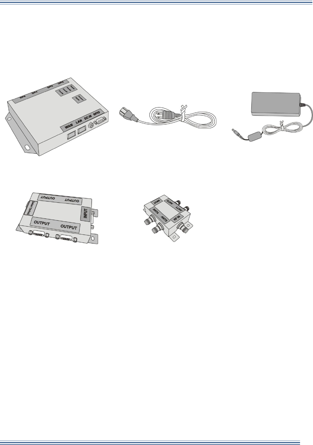
1.1 In the Package
RFID Smart Reader
Power Cord
Power Adapter
Fan-out Box (optional)
RF Switch (optional)
Note: The Fan-out Box and RF Switch work in combination to allow more antenna connections.
One RFID Smart Reader can connect to one Fan-out box and four RF switches.
1.2 Introduction
The WNC RFID Smart Reader (the Reader) is suitable for a variety of UHF RFID applications. It
provides high level RF performance, a user-friendly software development interface and a cost
competitive reader solution. Combined with a Newave Shelf Antenna, it can provide 100%
readability in zone sizes of 2’x2’x2’ to 10’x10’x10’ with appropriate reader parameters and
antenna setup. You can also connect the Reader to a fan-out box and 1~4 RF switches to add
additional antennas. A maximum of 16 antennas are allowed for one Reader.
For multi-reader applications, such as retail applications, the Reader solution can efficiently
compress data size and solve data traffic issues.
1 Getting Started WNC RFID Smart Reader
Wistron NeWeb Corporation© 3
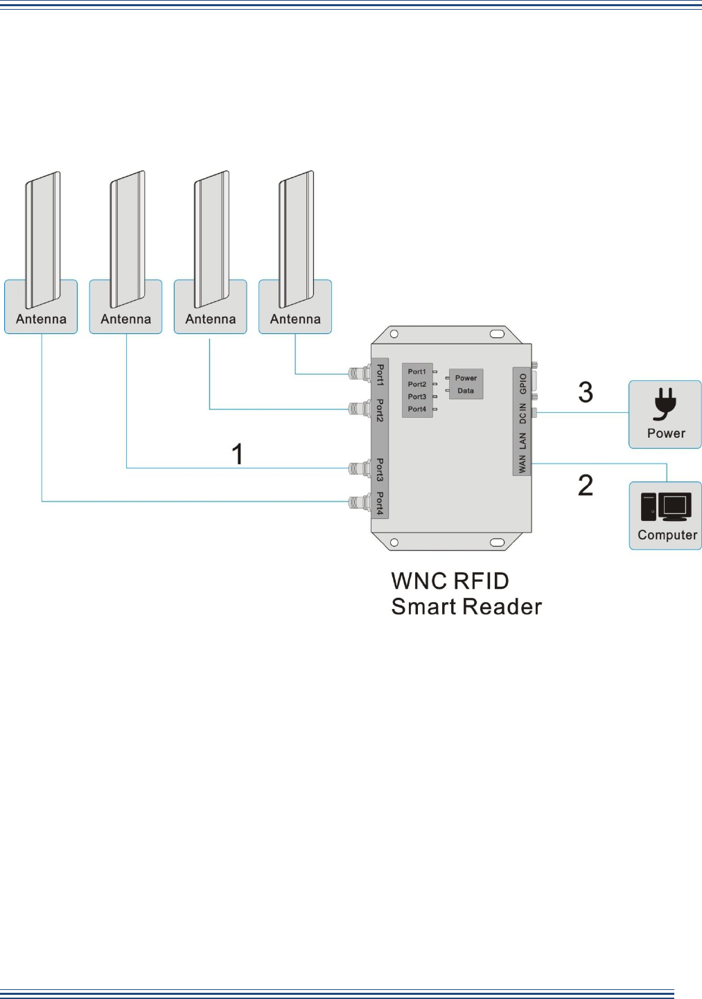
Basic application:
You can connect to up to four antennas and use a computer to monitor detected parameters.
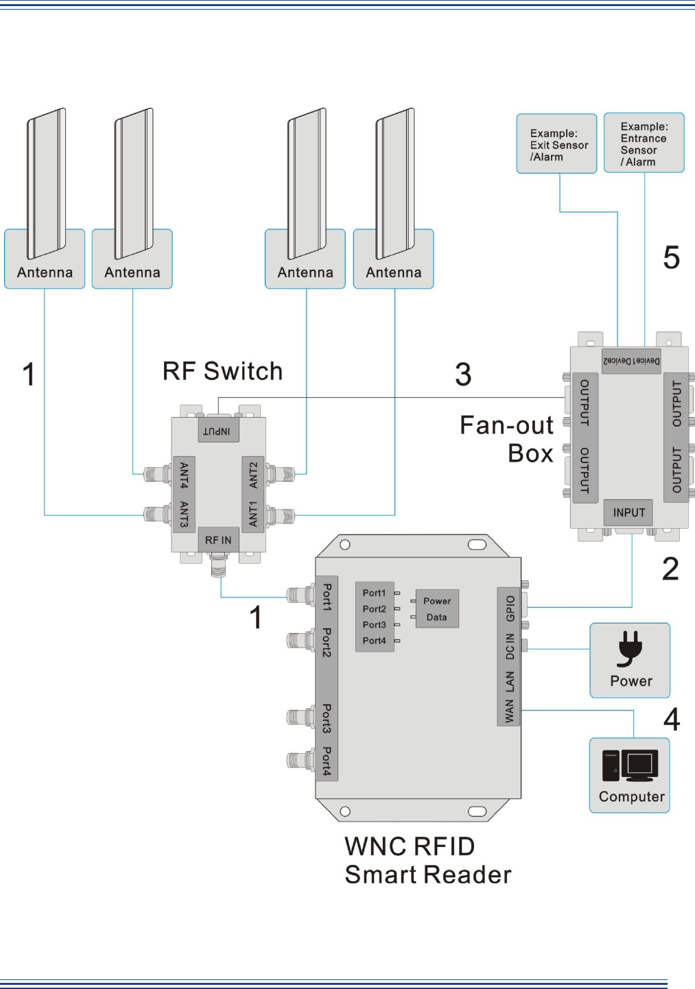
Advanced application:
Use the Reader with a Fan-out Box and an RF Switch to connect up to 16 antennas.
1 Getting Started WNC RFID Smart Reader
Wistron NeWeb Corporation© 4
1.3 Hardware Overview- RFID Smart Reader
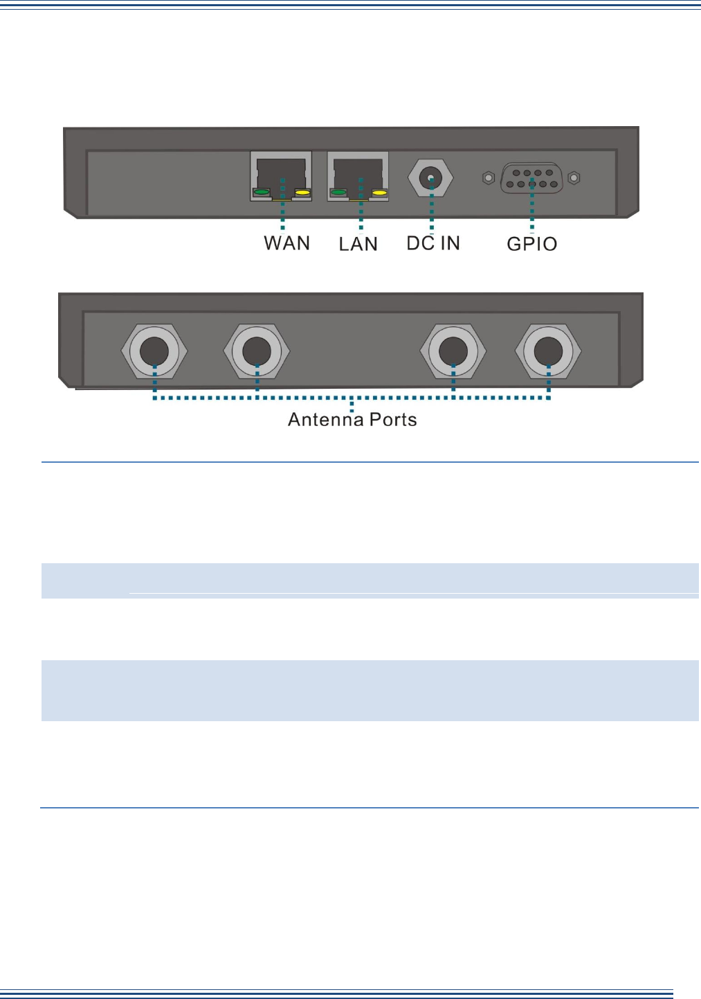
Front Panel
Rear Panel
WAN
Connect a standard RJ-45 Ethernet cable to the port to establish a network
connection. This feature allows you to configure settings or read the data
from the Reader on your computer via a Graphic User Interface. WAN port
supports Power over Ethernet (PoE).
LAN
Currently unavailable.
DC IN
Connect the power adapter to the Reader via this inlet to power on the
Reader.
GPIO
For GPIO purposes such as connecting a Fan-out Box, light sensor or other
sensors.
Antenna
Ports
For RF cable insertion. The Reader supports up to four antennas at the
same time. Additional connection is also possible via an optional antenna
switch.
Note: RJ-45 Ethernet cable and RF cable not included in the package.

1 Getting Started WNC RFID Smart Reader
Wistron NeWeb Corporation© 5
1.4 Hardware Overview- Fan-out Box
OUTPUT
For RF Switch connection.
INPUT
Connect to the GPIO port of the Reader.
Device
1 & 2
Sensor data input/output ports for other applications, for example,
connecting to entrance and exit sensors for security control.
1.5 Hardware Overview - RF Switch
INPUT
Connect to an OUTPUT port of the Fan-out Box.
RF IN
Connect to an antenna port of the Reader.
ANT 1~4
For antenna connection.
1 Getting Started WNC RFID Smart Reader
Wistron NeWeb Corporation© 6
1.6 Connecting the Cables
Basic installation:
1. Plug an RF cable into an antenna port and an antenna. The Reader supports up to four
antennas at the same time.
2. Connect an RJ-45 Ethernet cable to the WAN port and to your computer for software
development interface configuration.
3. Connect the power adapter to the DC IN inlet on the Reader. Once the power adapter is
connected to the Reader, the Power LED indicator will turn green indicating the power is on.
Note: Reader may be wall-mounted. Insert screws via the four holes on the left and right side of
the Reader.
1 Getting Started WNC RFID Smart Reader
Wistron NeWeb Corporation© 7
Installation with Fan-out Box and RF Switch:

1 Getting Started WNC RFID Smart Reader
Wistron NeWeb Corporation© 8
1. Use an RF cable to connect an antenna port of the Reader to the RF IN port of the RF
Switch, and then connect the antennas to the ANT1~4 ports of the RF Switch.
2. Use a DB9 cable to connect the GPIO port of the Reader and the INPUT port of the Fan-out
box.
Note: Only use a rollover type DB9 cable (not crossover type.) The cable must be shorter
than 5m.
3. Use a DB9 cable to connect an OUTPUT port of the Fan-out Box to the INPUT port of the
RF Switch.
Note: Only use a rollover type DB9 cable shorter than 30m.
4. Connect the Reader to a computer. Attach the power supply to the Reader and plug it into a
wall outlet.
5. You can also connect the Device1 & 2 ports to receive data from other devices such as
sensors.
Note: The Reader, Fan-out Box and the RF Switch may be wall-mounted. Insert screws via the
four holes on the left and right side of them.
1.5 LED Status (RFID Smart Reader)
Status
LED
Green
Red
Off
Power
On:
Powered on
On:
Power booting
No Power
Data
Blinking:
Data transmitting
N/A
No transmission
Port 1 ~ 4
On:
Port enabled
Blinking:
RF inventory
On:
Port error
Blinking:
RF failure
Port disabled

2 Software WNC RFID Smart Reader
Wistron NeWeb Corporation© 9
2. Configuration Software
2.1 Access the Management Interface
2.2 Management

3 Appendix WNC RFID Smart Reader
Wistron NeWeb Corporation© 10
3. Appendix
3.1 Specifications: RFID Smart Reader
RF System
Chipset
Impinj R2000
ATMEL AT91SAM7S-256
Protocol
RFID Protocol Support
EPC Global Gen 2
ISO 18000-6C; ISO 18000-6B (optional)
Support EPC DRM
Yes (with DRM Filter) switchable
RF
Frequency
US: 902 ~ 928MHz
EU: 865 ~ 868MHz
KR: 910 ~ 914MHz
PRC: 920 ~ 925MHz
Open: 840MHz ~ 960MHz
Demodulation
ASK or PSK
Modulation Depth
90% nominal
Data Encoding
FM0 or Miller code
Bit Rate
Supports uplink data rates of up to 640 Kbps
TX Output power
28 dBm
Antenna Type
4 port Mono-static
Antenna connector
4 pcs RP TNC
General Characteristics
Dimensions
18.2 x 13 x 2.6 cm
Weight
~550g
Base Material
Aluminum alloy (AL 5052)
Mounting
Wall, floor
Power Input
1. POE 802.3at
2. DC power input (12 VDC +/-5%, 30W)
Power Consumption
11W

3 Appendix WNC RFID Smart Reader
Wistron NeWeb Corporation© 11
System Architecture
Processor
TI TMS320DM6446
System Memory / Ram
64MB
Internal Storage / Flash
128MB
Communication
USB
N/A
Ethernet
10/100 Base-T (RJ-45) X2 (POE x 1 802.3 at compliant)
GPIO
4 input and 2 output (DB9)
Indicators
5 two-color / 1 one-color LED status indicator
Software
Operation System
Embedded Linux
Software SDK
C#
Environment
Humidity
5% to 95%, non-condensing
Operating Temperature
- 20℃ to 50℃ / -4°F to 122°F
Storage Temperature
- 40℃ to 85℃ / -40°F to 185°F
Sealing / Dust and Water
Immunity
IP54 (NEMA 3)

3 Appendix WNC RFID Smart Reader
Wistron NeWeb Corporation© 12
3.2 Specifications: Fan-out Box
RF System
Chipset
MC33202DR2G
Regulatory and Environmental Compliance
EMC certification
FCC 47 CFG Ch.1 Part 15 (US) (15.247)
ETSI EN 302 208-1 (V1.1.1) (EU) (optional)
Certification
RoHS / FCC / CE(optional)
General Characteristics
Dimensions
12.5 x 6.2 x 2.6 cm
Weight
~250g
Base Material
Aluminum alloy (AL 5052)
Mounting
Wall, floor
Power Consumption
0.5W
Communication
Input port
1 DB9 female connector
Output port
4 DB9 female connector
External port
2 ACES product:2.0mm WTB WAFER CONN
Environment
Humidity
5% to 95%, non-condensing
Operating Temperature
- 20℃ to 50℃ / -4°F to 122°F
Storage Temperature
- 40℃ to 85℃ / -40°F to 185°F
Sealing / Dust and Water
Immunity
IP54 (NEMA 3)

3 Appendix WNC RFID Smart Reader
Wistron NeWeb Corporation© 13
3.3 Specifications: RF Switch
RF System
Chipset
SN74HC139PWR
SN74HC240PWR
AS221
RF
Frequency
US: 902 ~ 928MHz/
EU: 865 ~ 868MHz/
KR: 910 ~ 914MHz/
PRC: 920 ~ 925MHz/
Open:840MHz ~ 960MHz/
Typical Insertion Loss
1.2dB
Typical Isolation
36dB
Regulatory and Environmental Compliance
EMC certification
FCC 47 CFG Ch.1 Part 15 (US) (15.247)
ETSI EN 302 208-1 (V1.1.1) (EU) (optional)
Certification
RoHS / FCC / CE(optional)
General Characteristics
Dimensions
11.4X5.8X2.6 cm
Weight
~350g
Base Material
Aluminum alloy (AL 5052)
Mounting
Wall, floor
Communication
Input port
1 DB9 female connector
R-TNC
4 R-TNC Connector
Environment
Humidity
5% to 95%, non-condensing
Operating Temperature
- 20℃ to 50℃ / -4°F to 122°F
Storage Temperature
- 40℃ to 85℃ / -40°F to 185°F
Sealing / Dust and
Water Immunity
IP54 (NEMA 3)
3 Appendix WNC RFID Smart Reader
Wistron NeWeb Corporation© 14
3.4 Pin Definition
GPIO port of RFID Smart Reader
DB9 Female connector
Pin1
5V
Pin2
Output port1, 3.2V
Pin3
Output port3, 3.2V
Pin4
Input port1, 3.2V
Pin5
Ground
Pin6
Ground
Pin7
Output port2, 3.2V
Pin8
Output port4, 3.2V
Pin9
Input port2, 3.2V
Output ports of Fan-out Box
Output Port
Pin1
5V
Pin2
GPO_1-
Pin3
NC
Pin4
GPO_2+
Pin5
Ground
Pin6
Ground
Pin7
GPO_1+
Pin8
GPO_2-
Pin9
NC
3 Appendix WNC RFID Smart Reader
Wistron NeWeb Corporation© 15
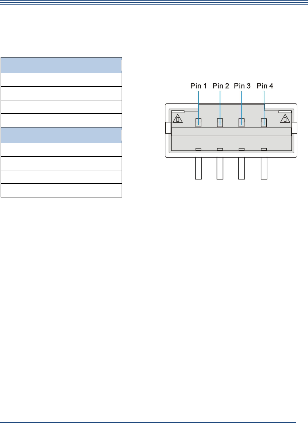
Device 1&2 ports of Fan-out Box
Device 1
Pin1
5V
Pin2
GPI_1
Pin3
GPO_3
Pin4
Ground
Device 2
Pin1
5V
Pin2
GPI_2
Pin3
GPO_4
Pin4
Ground
Federal Communication Commission Interference Statement
This device complies with Part 15 of the FCC Rules. Operation is subject to the following
two conditions: (1) This device may not cause harmful interference, and (2) this device
must accept any interference received, including interference that may cause undesired
operation.
This equipment has been tested and found to comply with the limits for a Class B digital
device, pursuant to Part 15 of the FCC Rules. These limits are designed to provide
reasonable protection against harmful interference in a residential installation. This
equipment generates, uses and can radiate radio frequency energy and, if not installed and
used in accordance with the instructions, may cause harmful interference to radio
communications. However, there is no guarantee that interference will not occur in a
particular installation. If this equipment does cause harmful interference to radio or
television reception, which can be determined by turning the equipment off and on, the user
is encouraged to try to correct the interference by one of the following measures:
- Reorient or relocate the receiving antenna.
- Increase the separation between the equipment and receiver.
- Connect the equipment into an outlet on a circuit different from that
to which the receiver is connected.
- Consult the dealer or an experienced radio/TV technician for help.
FCC Caution: Any changes or modifications not expressly approved by the party
responsible for compliance could void the user's authority to operate this equipment.
This transmitter must not be co-located or operating in conjunction with any other antenna
or transmitter.
Radiation Exposure Statement:
This equipment complies with FCC radiation exposure limits set forth for an uncontrolled
environment. This equipment should be installed and operated with minimum distance
20cm between the radiator & your body.
台灣使用注意事項:
經型式認證合格之低功率射頻電機,非經許可,公司、商號或使用者均不得擅自
變更頻率、加大功率或變更原設計之特性及功能。
低功率射頻電機之使用不得影響飛航安全及干擾合法通信;經發現有干擾現象
時,應立即停用,並改善至無干擾時方得繼續使用。前項合法通信,指依電信法
規定作業之無線電通信。低功率射頻電機須忍受合法通信或工業、科學及醫療用
電波輻射性電機設備之干擾