Wistron NeWeb CAP-1 802.11 a+g Super A/G Intelligent WLAN Access Point User Manual for 802 11a g Access Point
Wistron NeWeb Corporation 802.11 a+g Super A/G Intelligent WLAN Access Point for 802 11a g Access Point
UserManual.wiki
>
Wistron NeWeb
>
CAP 1 User Manual
User Manual
Navigation menu
Upload a User Manual
Namespaces
Wiki Guide
HTML
PDF
Info
Views
User Manual
Discussion / Help
Navigation
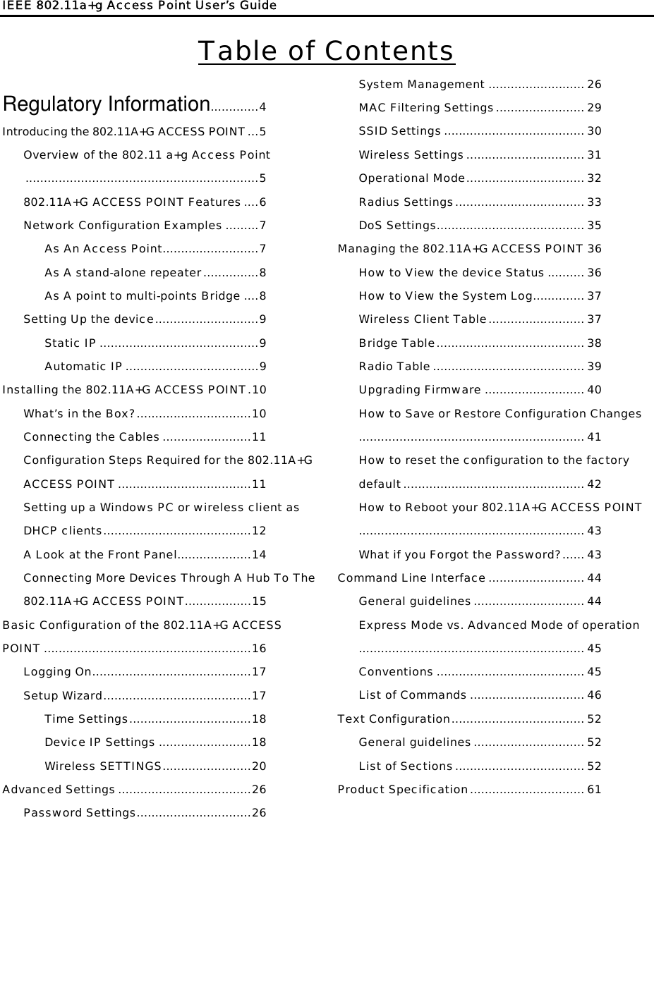
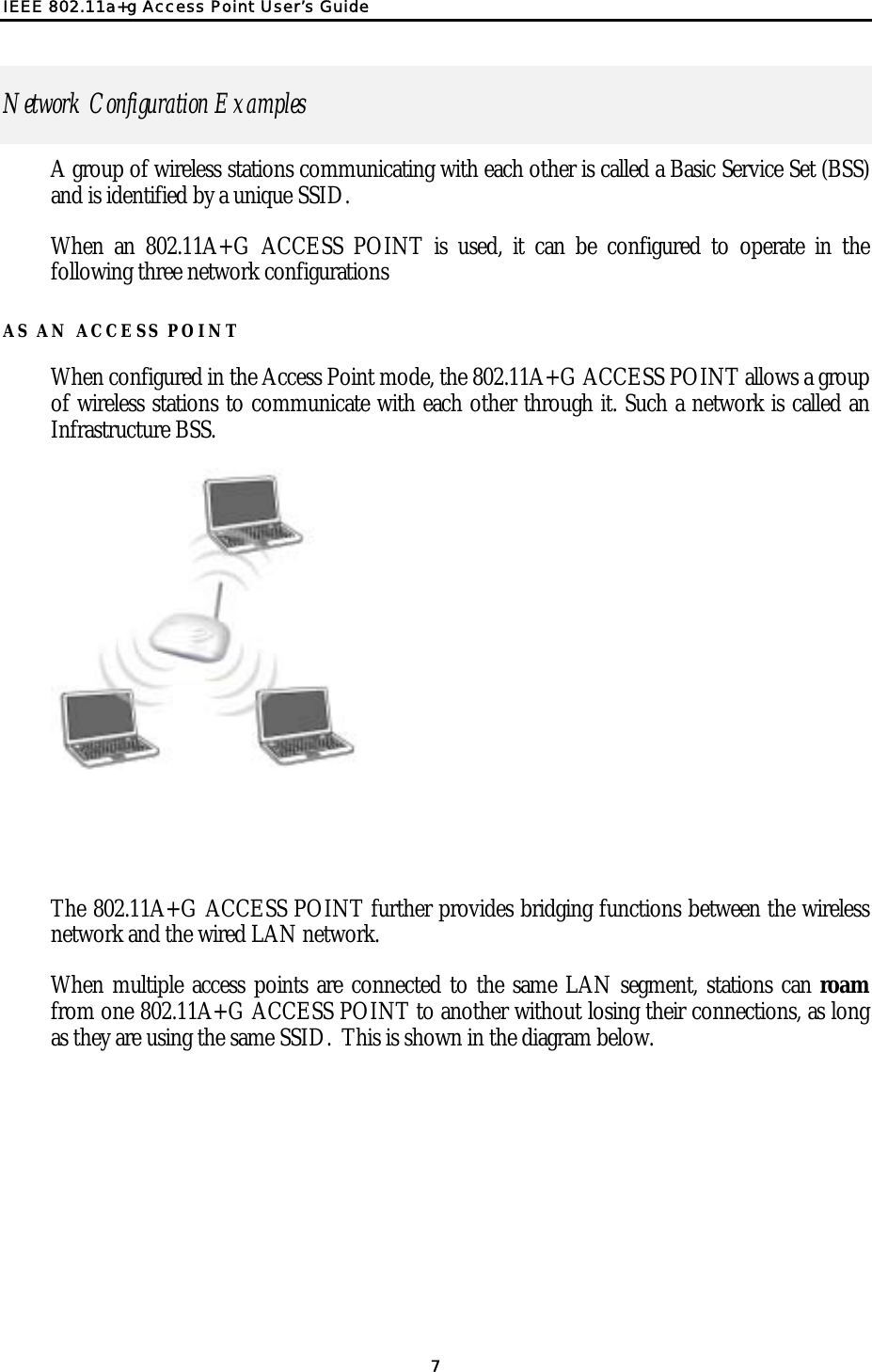

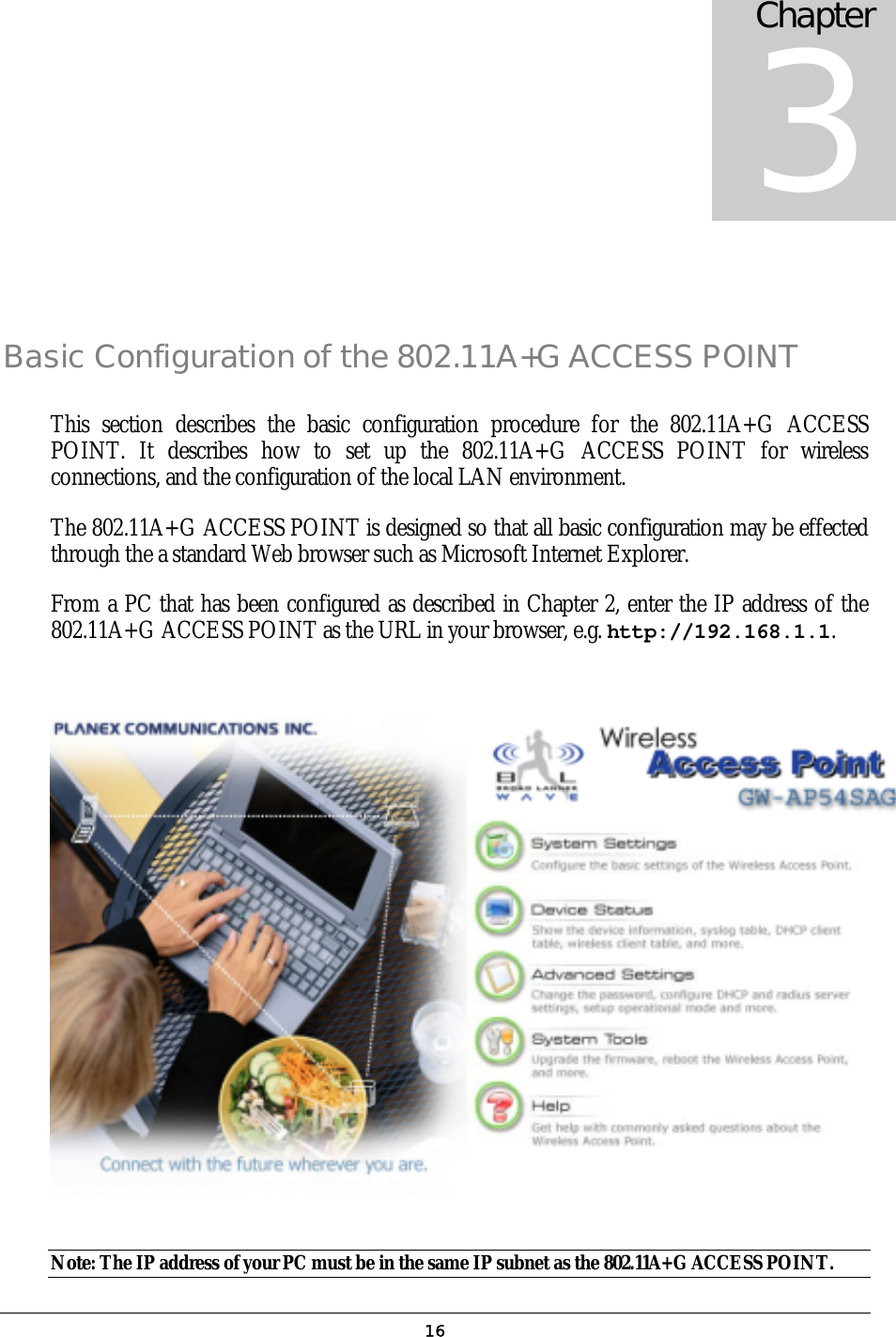
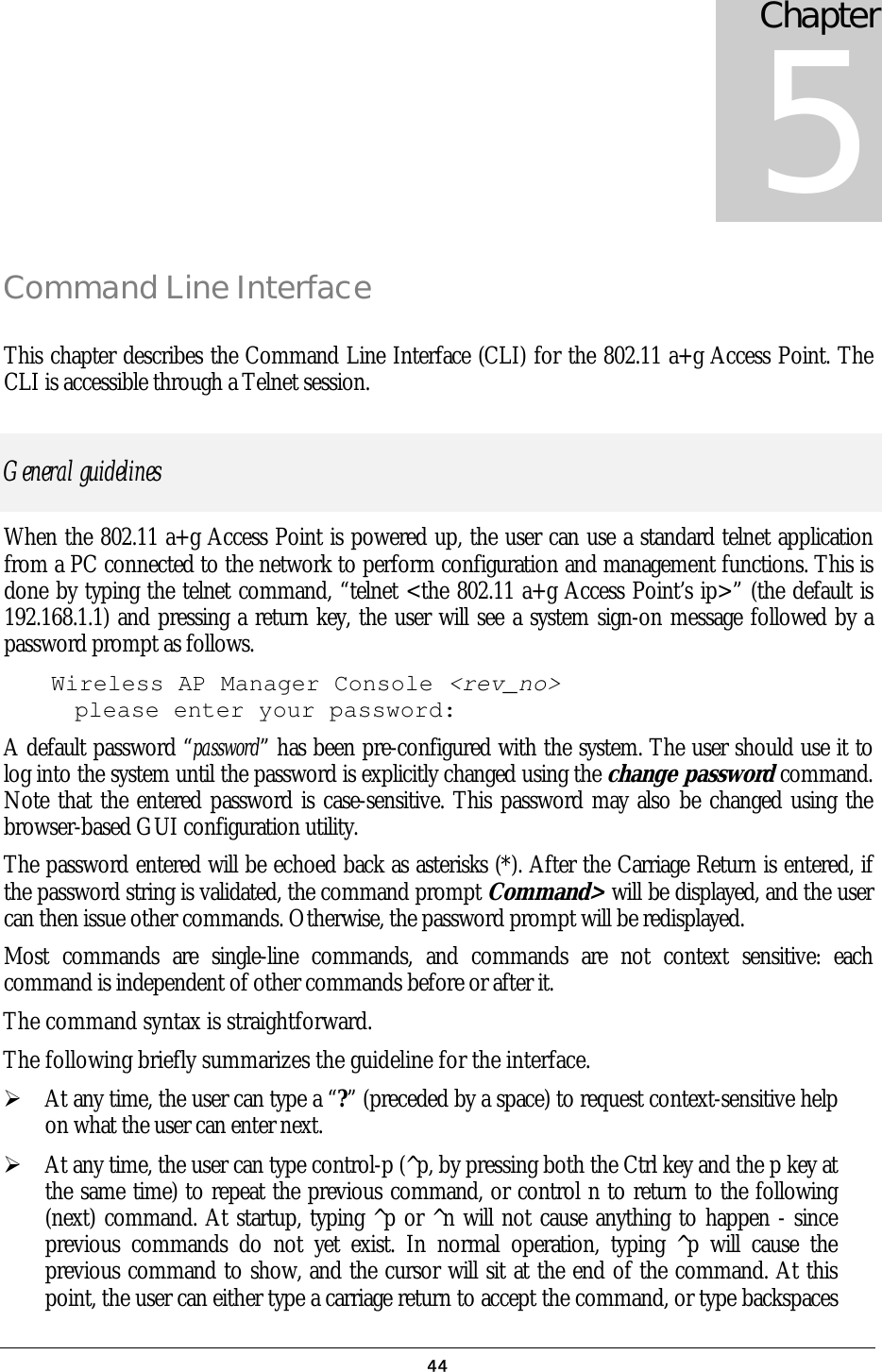
![ wlan means the Wireless port; <> specifies the arguments of the command, <1-4> means a number between 1 to 4; [ ] indicates an optional parameter | is used to separate alternative choices of parameters or keywords; {} encloses all alternative keywords; MacAddr, or XX-XX-XX-XX-XX-XX means any MAC address in hexadecimal format, where each XX can be 00, 01, ... 99, 0A, 0B, 0C, 0D, 0E, 0F, 10, 11,… FF; ipAddr, netmask, or xxx.xxx.xxx.xxx means any ip address or network mask, where xxx is a decimal integer between 0 and 255; The term string means a string of characters up to the specified length, which may be enclosed in double quotes (“) (required if the string contains embedded blanks); Names representing filters and MAC addresses could be up to 30 characters in length; password and SNMP community read/write strings are up to 15 characters in length. When the password and SNMP community write string are entered, they are echoed back as a string of “*”s for protection, while other parameters, such as WEP keys, are echoed back the way they are typed (in clear text). List of Commands From a functional point of view, CLI commands will be grouped into the following categories: (1) System (2) Filtering (3) SNMP (4) Diagnostics (5) Security The command format will be described in the following sections. (1) System Commands clear config Description: Reset the system configuration to the factory default. disable upnp Description: Disable the UPnP function. disable wlan management 46](https://usermanual.wiki/Wistron-NeWeb/CAP-1/User-Guide-422879-Page-46.png)
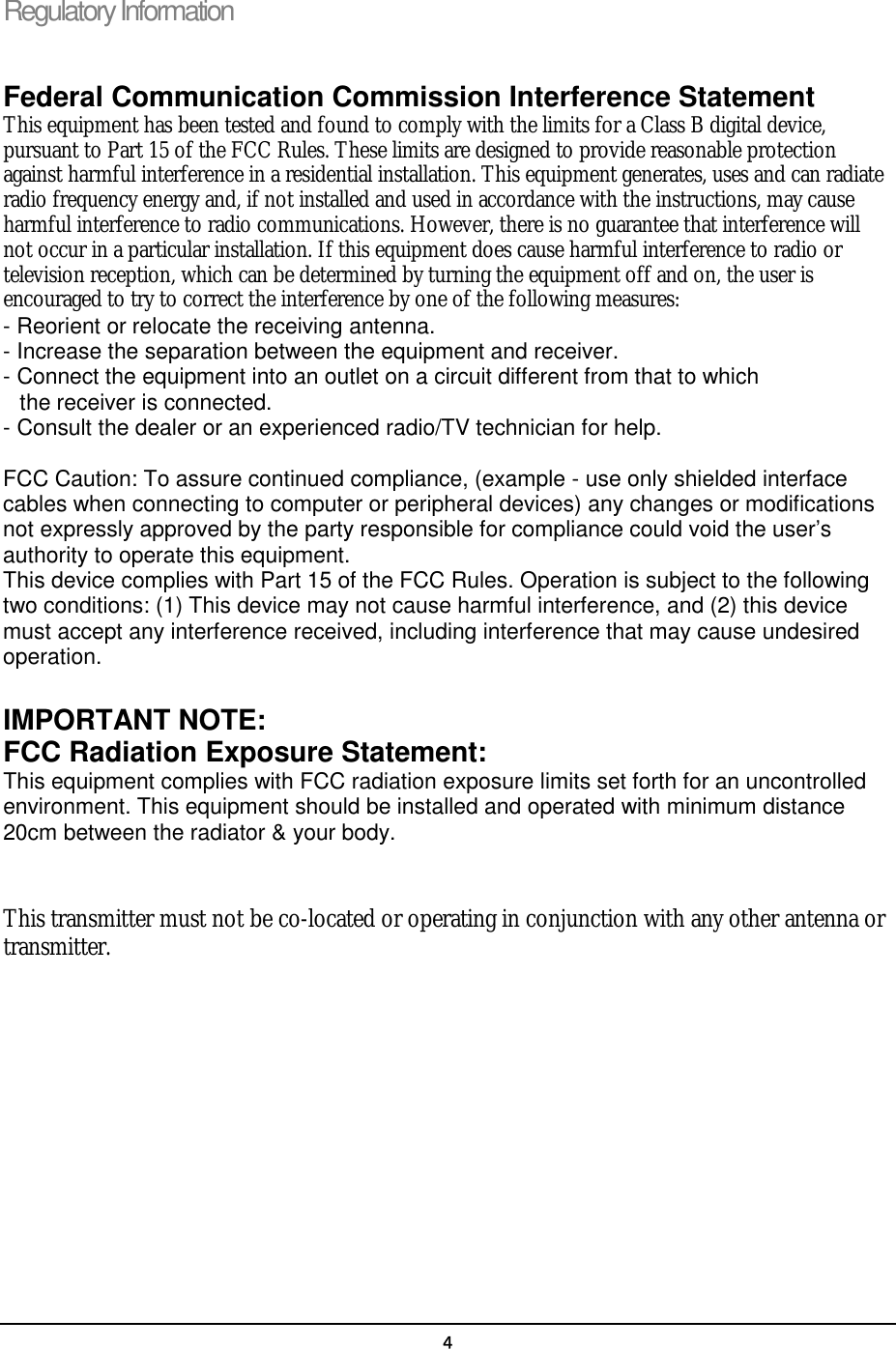
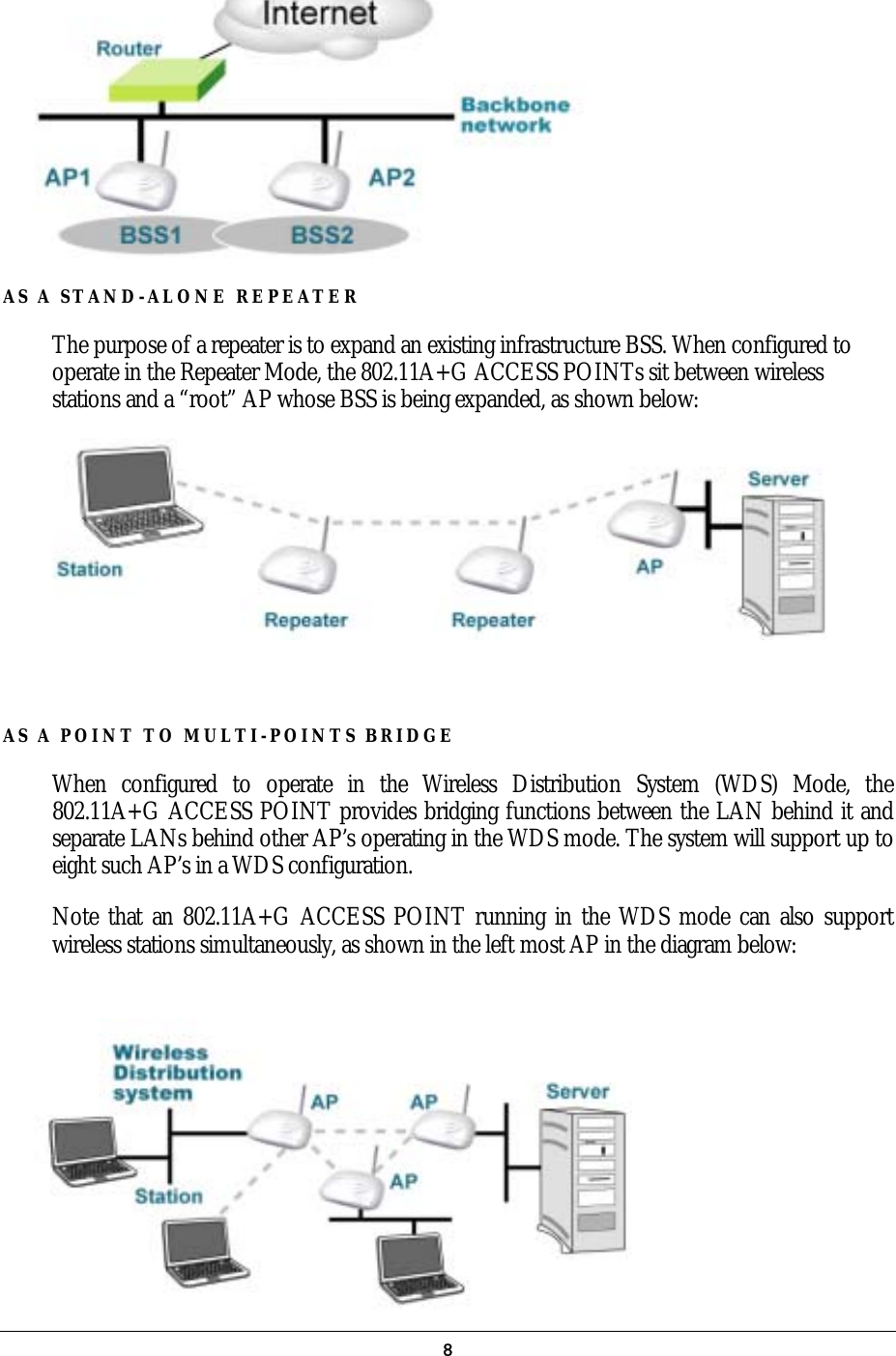
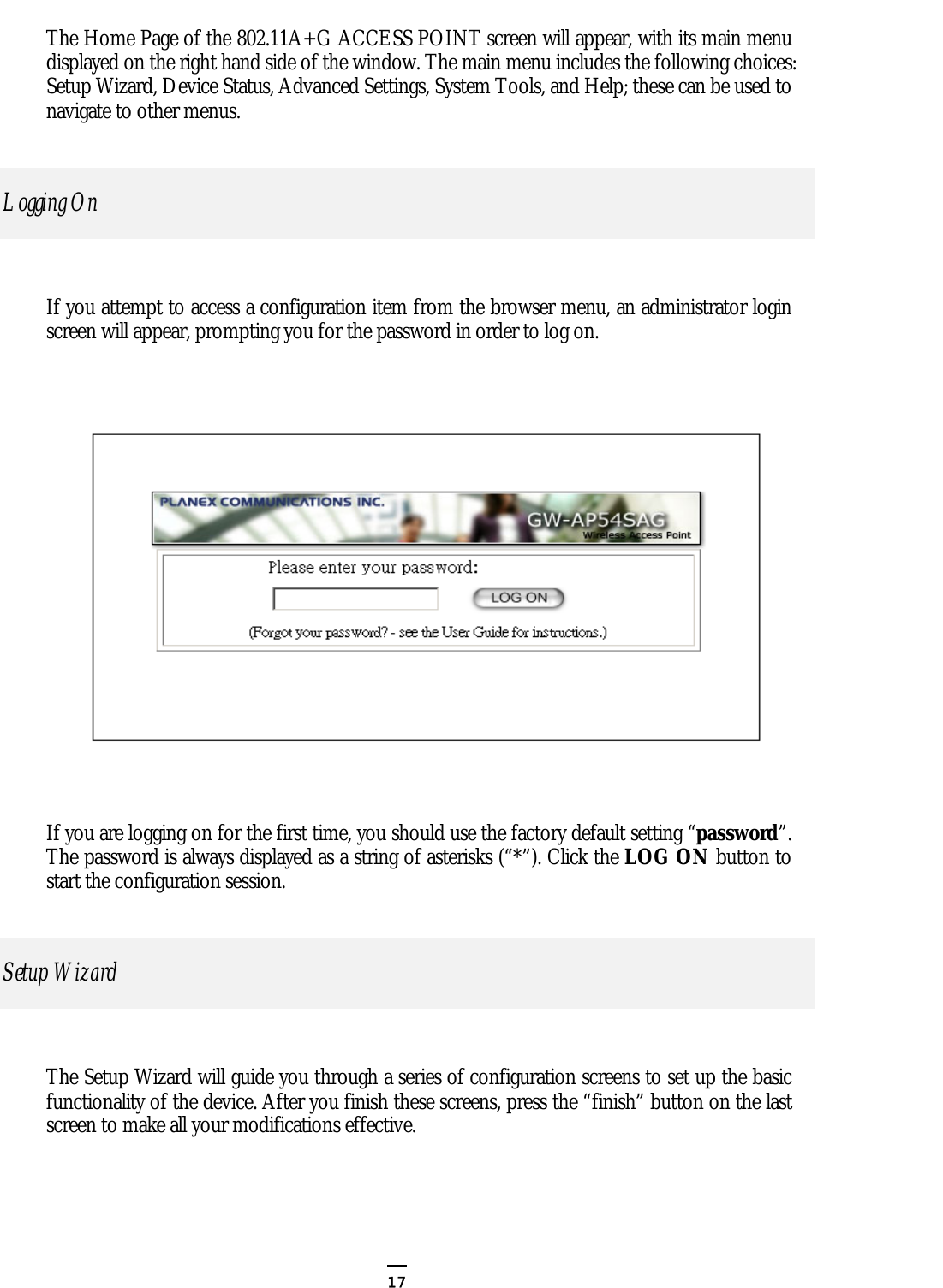
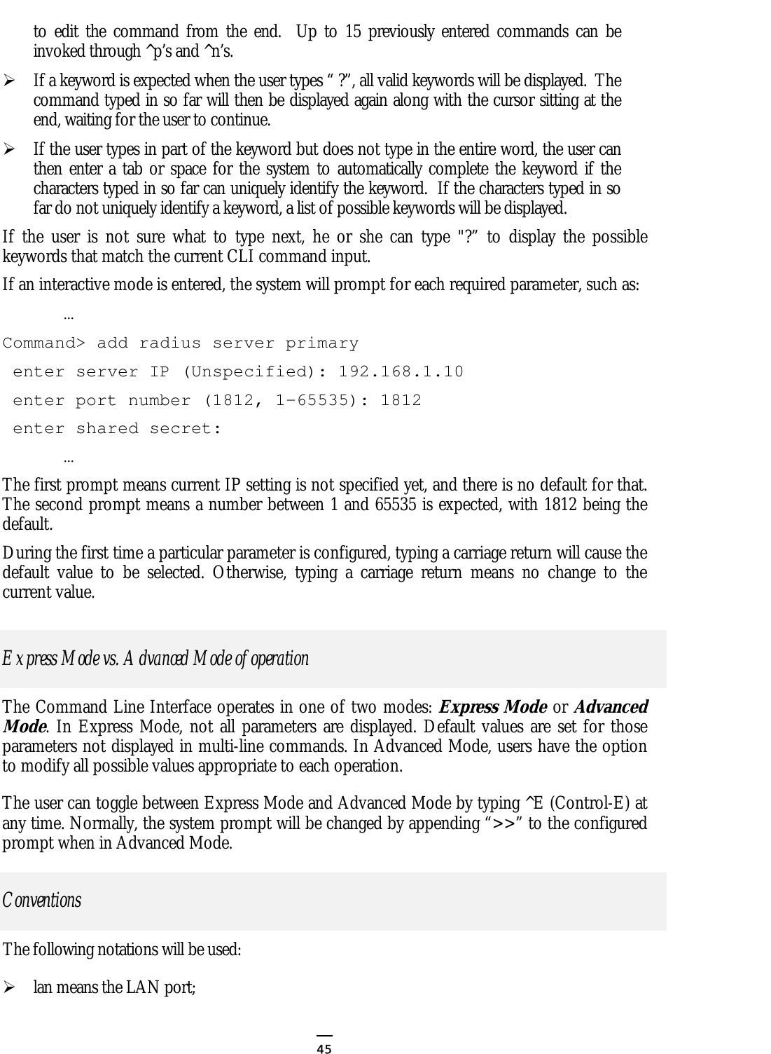
![Description: Add a MAC filter with the specified name (a mnemonic name) and MAC address. delete mac filter <string up to 30 characters> Description: Delete the MAC filter with the specified name. set mac filter mode <MAC filter mode, disabled/grant/deny> Description: Set the MAC filter mode. show mac filter [<string up to 30 characters>] Description: Display the MAC filter entry with the specified name. If no name is specified, this command display all currently configured MAC filter entries. show mac filter mode Description: Display the currently configured MAC filter mode. (3) SNMP Commands disable snmp Description: Disable the SNMP function. enable snmp Description: Enable the SNMP function. set community string {read | write} <string up to 15 characters> Description: Configure the SNMP READ/WRITE community string. show community string read Description: Display the SNMP READ community string. show snmp Description: Display the current SNMP settings. show snmp statistics Description: Display the current SNMP statistics. show trap manager [<string up to 30 characters>] Description: Display the settings of the specified SNMP trap manager. If no trap manager is specified, this command displays the settings of all trap managers. 49](https://usermanual.wiki/Wistron-NeWeb/CAP-1/User-Guide-422879-Page-49.png)
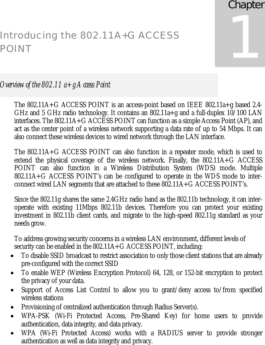
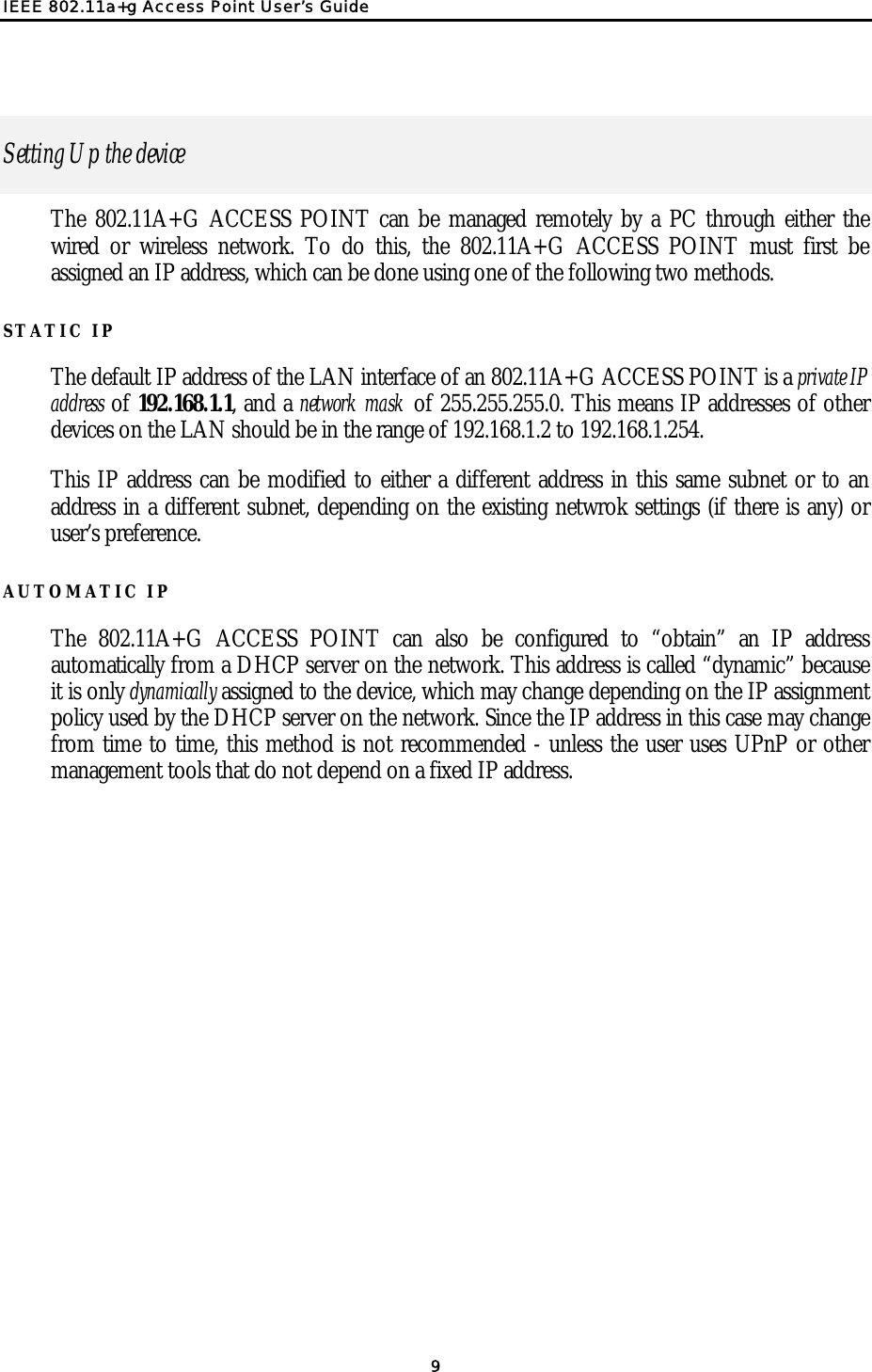
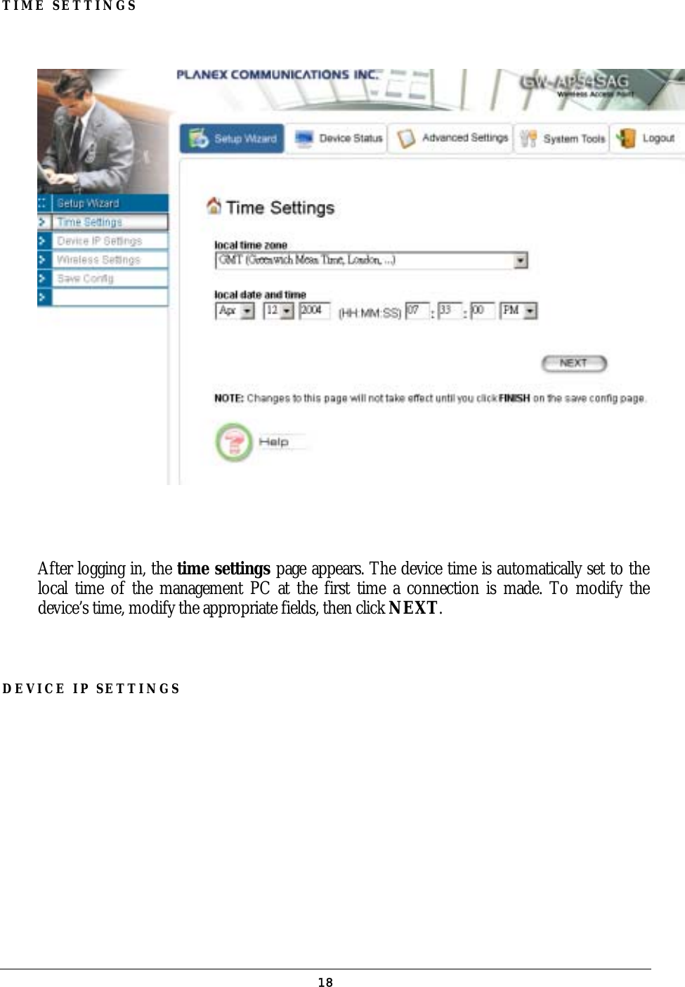
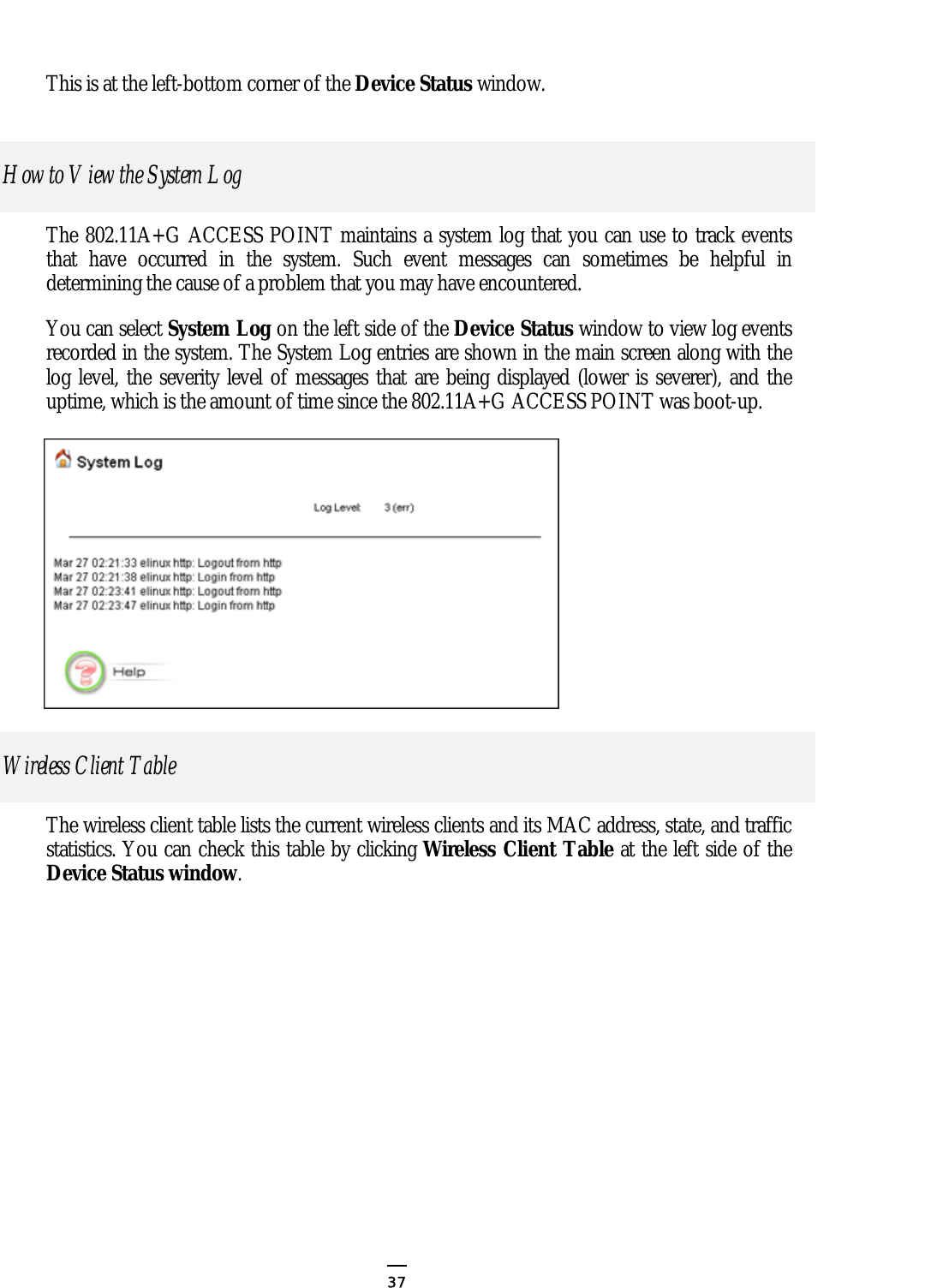
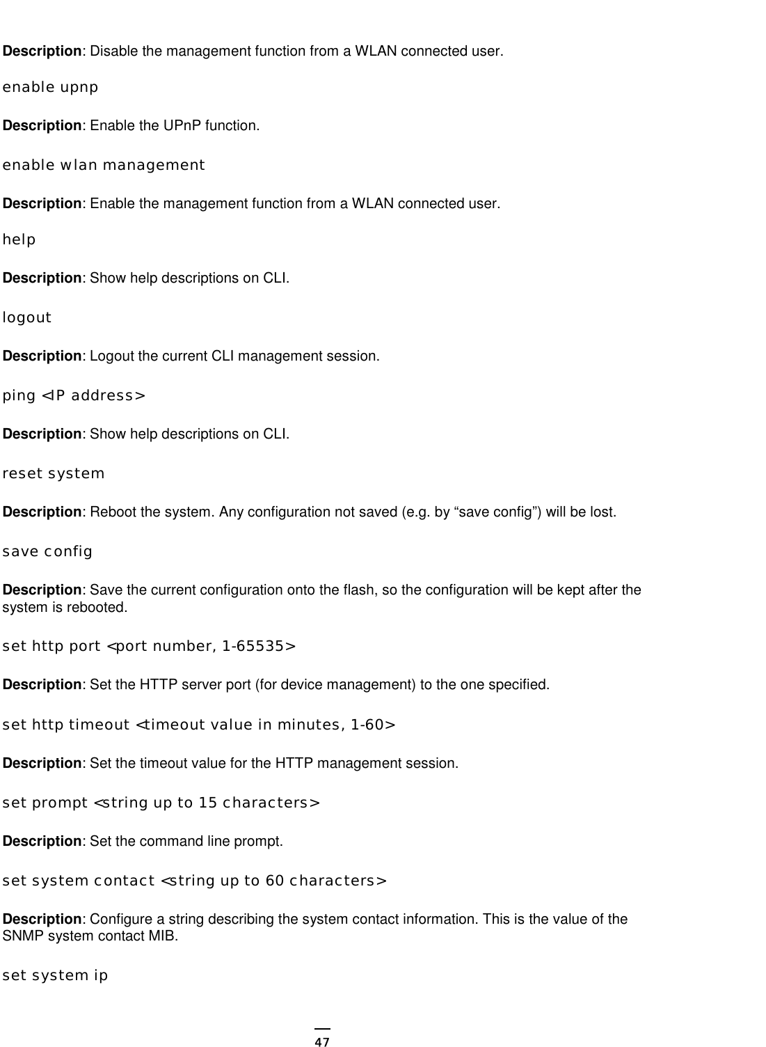
![(4) Diagnostics Commands disable log <facility> Description: Disable the log function on the specified facility. disable syslogd Description: Disable the remote log function. disable trace <facility> Description: Disable the trace function on the specified facility. enable log <facility> [<log level, 1-7>] Description: Enable the log function with the specified log level on the specified facility. If no log level is specified, the previously configured log level is used. enable syslogd Description: Enable the remote log function. enable trace <facility> [<log level, 1-7>] Description: Enable the trace function with the specified log level on the specified facility. If no log level is specified, the previously configured log level is used. set log level <log level, 1-7> Description: Set the log level. set syslogd <IP address> Description: Configure the IP address of the remote syslog daemon. This is used for the remote syslog function. show log level Description: Display the current log level. show log table [<facility>] Description: Display the current logged events of the specified facility. If no facility is specified, this command displays all logged events. show syslogd Description: Display the current configuration of the remote log function. (5) Security Commands add radius server {primary | secondary} 50](https://usermanual.wiki/Wistron-NeWeb/CAP-1/User-Guide-422879-Page-50.png)
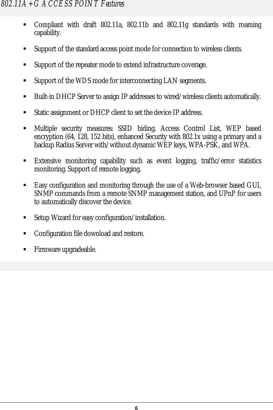
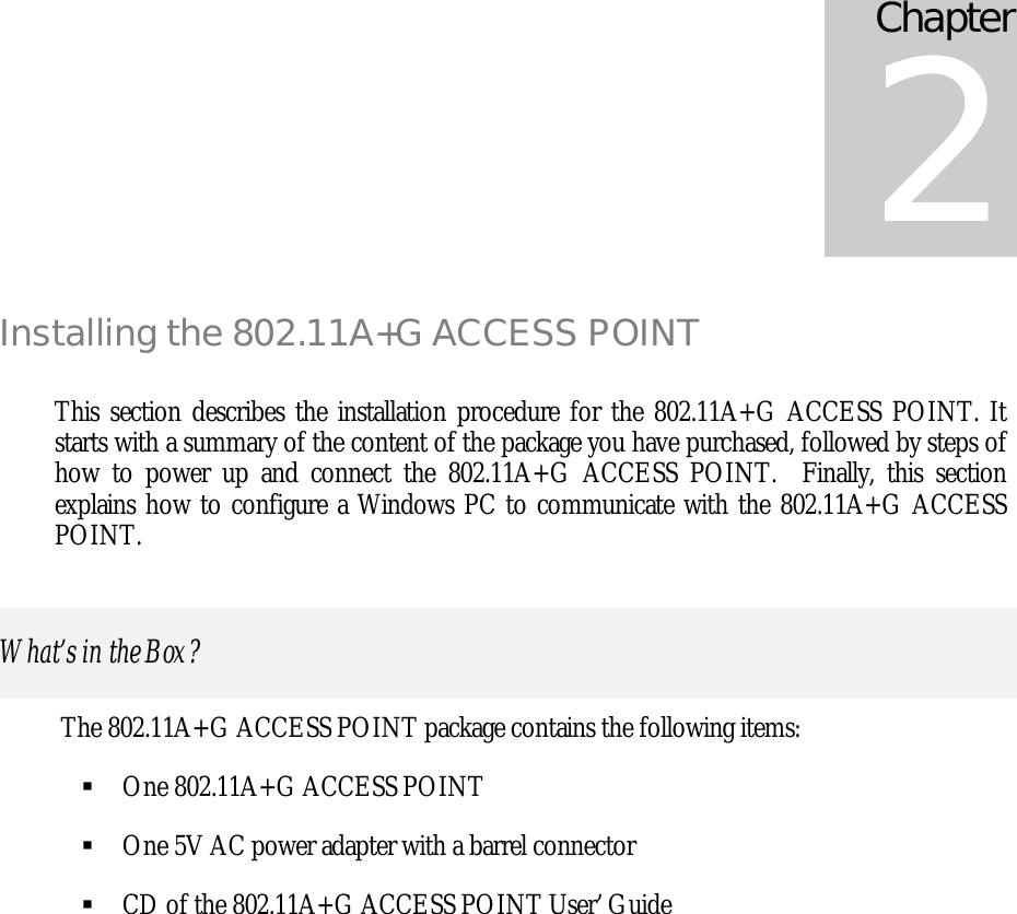
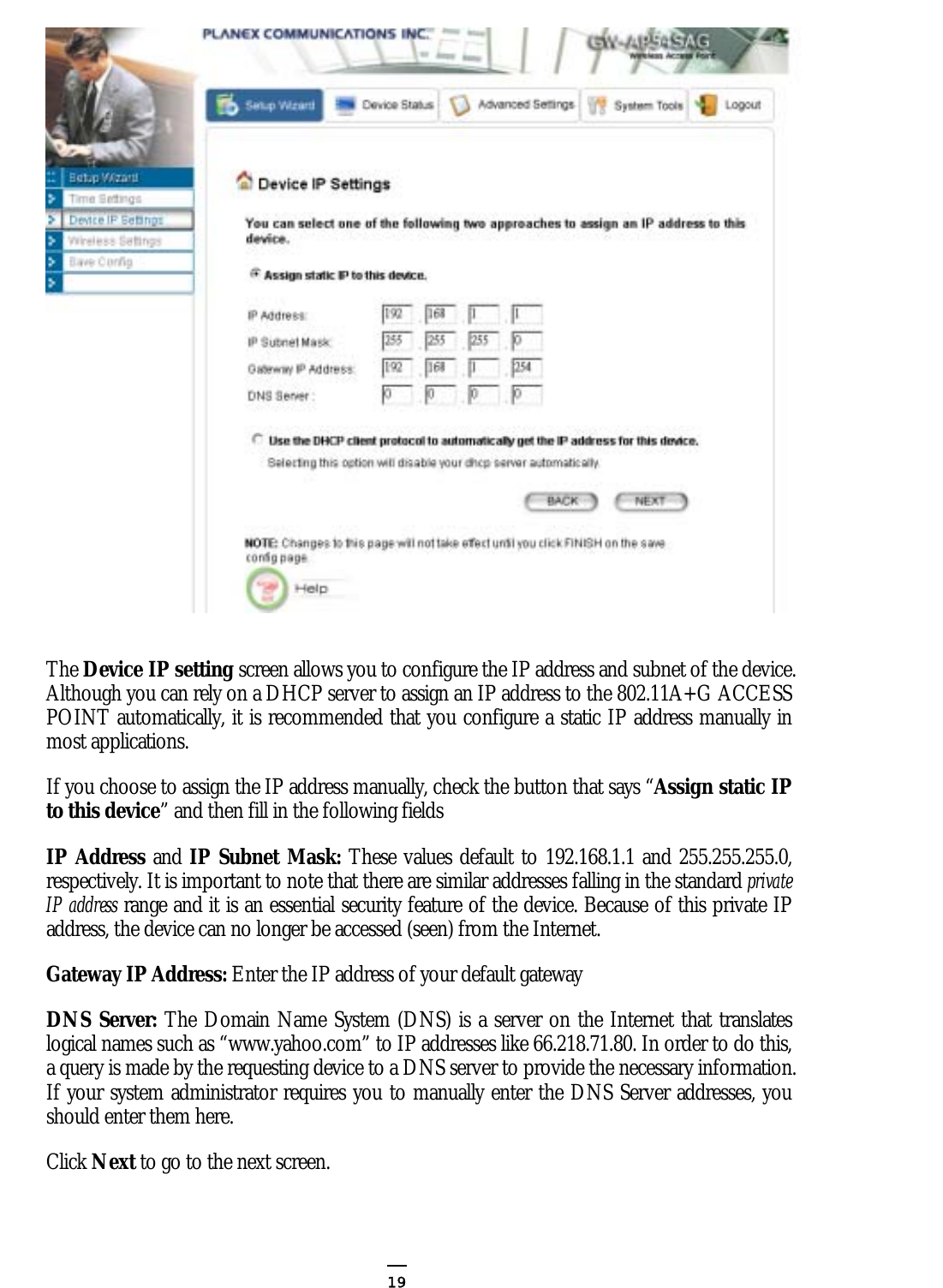
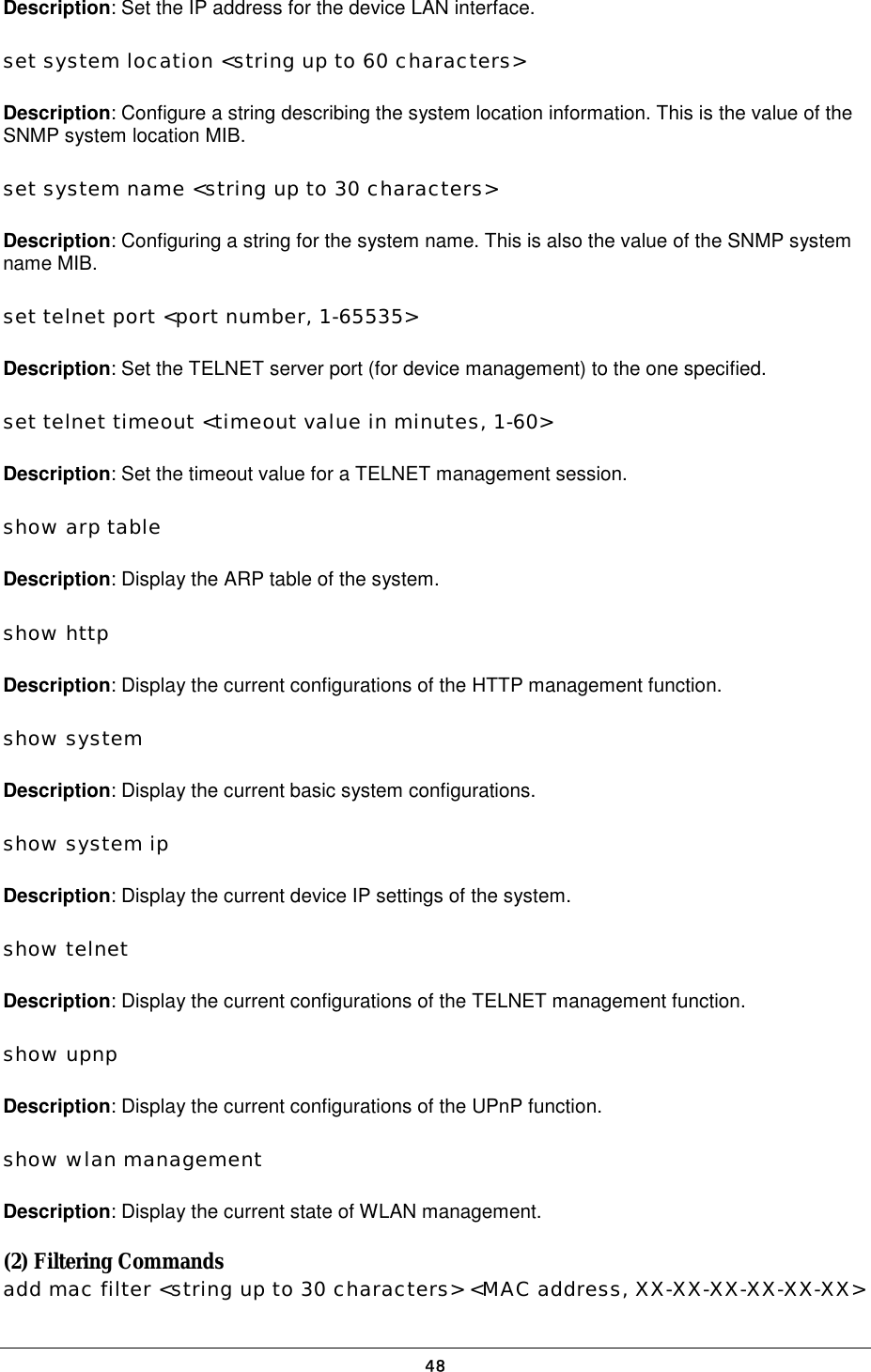
![Description: Configure the primary/secondary RADIUS server settings. This is a multi-line command, and you have to enter the IP address and port number of the server, shared secret, and enable/disable. change password Description: Change the password for management, including HTTP and TELNET. disable radius mac authentication Description: Disable the use of external RADIUS servers for MAC address access control. disable radius server {primary | secondary} Description: Disable the use of the primary/secondary RADIUS server. enable radius mac authentication Description: Enable the use of external RADIUS servers for MAC address access control. enable radius server {primary | secondary} Description: Enable the use of the primary/secondary RADIUS server. set radius server reattempt <reattempt interval in minutes, 5-60> Description: Configure the reattempt time for the system to contact the primary RADIUS server after the primary RADIUS server was down. set radius server retry <retry interval in times, 1-5> Description: Configure the number of retries after which the system may think the RADIUS server is down. show radius server [{primary | secondary}] Description: Display the configuration of the specified RADIUS server. If no server is specified, this command displays the configurations of all RADIUS servers. 51](https://usermanual.wiki/Wistron-NeWeb/CAP-1/User-Guide-422879-Page-51.png)
![Text Configuration The text configuration provides another way for users to configure the 802.11 a+g Access Point. Users can save the system current configuration onto a file on PC, edit the configuration file, and then restore the system configuration with the configuration file. For details regarding the save and restore configuration operations, please read the HOW TO SAVE OR RESTORE CONFIGURATION CHANGES section in the MANAGING YOUR 802.11A+G Access Point chapter. This chapter describes the syntax and semantics of a text configuration file. General guidelines The format of a text configuration file is like the Microsoft Window® INI (extension file name: .ini) file format. The basic file structure can be divided into the following parts: 1. Sections A section name is enclosed in square brackets, alone on a line. Section names are allowed to contain any character but square brackets or linefeeds. For example: “[sectionName]”. Basically a section corresponds to a configuration item, a section contains zero or more key and value pairs that are the settings for the configuration item. A section name is case insensitive. 2. Keys and Values A section contains zero or more key and value pairs, declared with the syntax “key = value”. A key is a string without space and the value consists of all characters at the right hand side of the equal sign. That is, a key starts with the first non-blank ASCII character at the right hand side of an equal sign and extends to a comment mark (if there is one) or the end of the line. So blanks are allowed among non-blank characters. A key string is case insensitive. 3. Comments A comment starts with a semicolon or a hash sign and extends to the end of the line. List of Sections Section & Examples Description Chapter 6 52](https://usermanual.wiki/Wistron-NeWeb/CAP-1/User-Guide-422879-Page-52.png)
![[Manufacture] Version = 1.00 This is used by the system itself, and this should be put as the first section in a configuration file. Users should not modify anything in this section. [Password] Password=000000 Password: the password for system management. [Time] TimeZone = +09:00 System Time Configuration TimeZone: the time zone of the system. Possible values are -12:00, -11:00, -10:00, …, +00:00, +01:00, …, +13:00. [Device] IPType=static IPAddress=192.168.1.1 IPNetmask=255.255.255.0 GatewayIP=192.168.1.254 DNSIP=168.95.1.3 IPType=dhcp Device IP Configuration IPType: the device IP type (‘static’ or ‘dhcp’) For ‘static’ type: IPAddress/IPNetmask: the IP address and network mask of the device. GatewayIP: the IP address of the default gateway. DNSIP: the IP address of the DNS. [ISP] ISPType=static ISPStaticIP=100.0.0.1 ISPNetmask=255.255.0.0 ISPGateway=100.0.0.2 ISPDNSIP=123.0.0.1 ISPType=dhcp Hostname=name ISPType=pppoe PPPoEUserName=name PPPOEPassword=password PPPOEServiceName=service PPPOEConnectionType=demand_dialing PPPOEMTU=1492 PPPOEMRU=1492 PPPOESessionType=normal PPPOESessionType=unnumbered_link KeepPrivateLan=enable/disable UnnumberedIP=192.168.1.1 UnnumberedNetmask=255.255.255.0 WAN Interface Configuration ISPType: the WAN connection type (‘static’, ‘dhcp’, ‘pppoe’, ‘pptp’). For ‘static’ type: ISPStaticIP: the IP address assigned by ISP. ISPNetmask: the netmask assigned by ISP. ISPGateway: the default gateway address assigned by ISP. ISPDNSIP: the DNS server address assigned by ISP. For ‘dhcp’ type: Hostname: the host name (if any) assigned by your ISP. For ‘pppoe’ type: PPPoEUserName: user name of the ISP account PPPOEPassword: password for the ISP account PPPOEServiceName: service name for the connection PPPOEConnectionType: type of the PPP connection (‘demand_dialing’, ‘always_on’, ‘manually’). PPPOEMTU/PPPOEMRU: the MTU/MRU for the connection (unit: byte). PPPOESessionType: type of the PPPoE session (‘normal’, ‘multiple_pppoe’, ‘unnumbered_link’). 53](https://usermanual.wiki/Wistron-NeWeb/CAP-1/User-Guide-422879-Page-53.png)
![ISPType=pptp PPTPLocalIP=11.0.0.10 PPTPNetmask=255.255.255.0 PPTPRemoteIP=11.0.0.1 PPTPUserName=name PPTPPassword=password PPTPIdleTimeout=time For PPPoE ‘unnumbered_link’ session type: KeepPrivateLan: keep the private LAN or not (‘enable’ or ‘disable’). UnnumberedIP: the IP address of the private LAN if ‘KeepPrivateLan’ is ‘enable’ UnnumberedNetmask: the subnet mask of the private LAN if ‘KeepPrivateLan’ is ‘enable’ For ‘pptp’ type: PPTPLocalIP: the local IP address for establishing the PPTP tunnel. PPTPNetmask: the subnet mask of the WAN interface where the PPTP tunnel is established. PPTPRemoteIP: the remote IP address for establishing the PPTP tunnel. PPTPUserName: the user name of the ISP account. PPTPPassword: the password name of the ISP account. PPTPIdleTimeout: the maximum idle time before the connection is taken down (unit: minute). [MultiplePPPoEEntry] MpppoeSessionName=session name MpppoeUserName=name MpppoePassword=password MpppoeConnectionType=manually MpppoeMTU=1492 MpppoeMRU=1492 MpppoeLanType=enable MpppoeLanIP=2.2.0.0 MpppoeLanNetmask=255.255.0.0 TPIPRange=enable TPPortRange=disable TPKeyword=disable TPNetBios=enable TPRuleIPRange=50.0.0.0-20 TPRuleNetwork=60.0.0.0/24 TPRulePortRange=40000-50000 TPRuleKeyword=key pattern Multiple PPPoE Sessions Configuration There could be multiple entries (max 7 entries), each entry contains the following items: MpppoeSessionName: a mnemonic name for this entry. MpppoeUserName: the user name for the ISP account. MpppoePassword: the password for the ISP account.MpppoeConnectionType: type of the PPP connection (‘demand_dialing’, ‘always_on’, ‘manually’). MpppoeMTU/MpppoeMRU: the MTU/MRU for the connection (unit: byte). MpppoeLanType: Enable the LAN type access on the session or not (‘enable’ or ‘disable’) MpppoeLanIP: the IP address of the LAN type network if ‘MpppoeLanType’ is ‘enable’. MpppoeLanNetmask: the subnet mask of the LAN type network if ‘MpppoeLanType’ is ‘enable’. TPIPRange: whether enable IP address range and network traffic pattern on the session (‘enable’, ‘disable’). TPPortRange: whether enable port range traffic pattern on the session (‘enable’, ‘disable’). TPKeyword: whether enable keyword traffic pattern on the session (‘enable’, ‘disable’). 54](https://usermanual.wiki/Wistron-NeWeb/CAP-1/User-Guide-422879-Page-54.png)
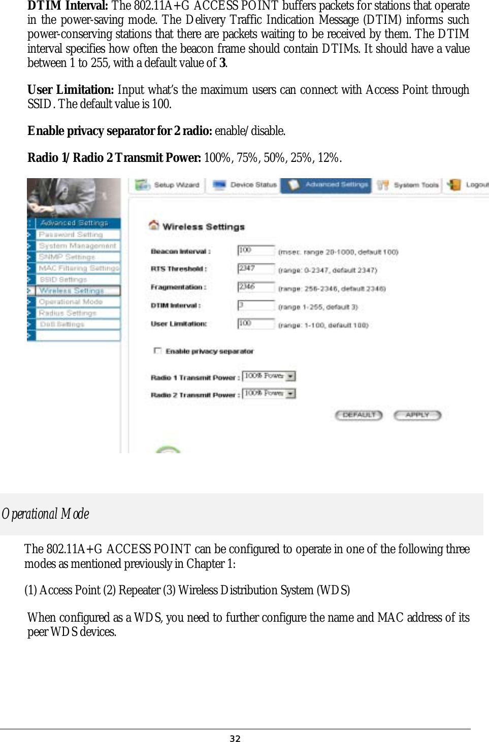
![TPNetBios: whether enable NetBIOS traffic pattern on the session (‘enable’, ‘disable’). The following items can appear more than one in a multiple PPPoE entry: TPRuleIPRange: specify an IP address range traffic pattern. TPRuleNetwork: specify an IP network traffic pattern. TPRulePortRange: specify a port range traffic pattern. TPRuleKeyword: specify a keyword traffic pattern. [CloneMAC] CloneMACState=disable CloneMAC=00-01-02-03-04-05 Clone MAC Configuration CloneMACState: whether enable the clone MAC function (‘disable’, ‘enable’). CloneMAC: the MAC address to be cloned. [Radio] SSIDBoradcast=enable Radio1Mode=11a Radio1Channel=auto Radio2Mode=11g/b Radio2Channel=auto Radio1TxPower=100 Radio2TxPower=100 PrivSeparatorState=disable BeaconInterval=100 RTSThreshold=2347 Fragmentation=2346 DTIMInterval=3 UserLimit=100 WLAN Configuration SSIDBoradcast: whether enable SSID broadcast. Radio1Mode: radio mode of radio 1 (‘11a’, ‘11at’-a turbo, ‘11sa’-super a without turbo, ‘11sast’-super a with static turbo, ‘11sadt’-super a with dynamic turbo). Radio2Mode: radio mode of radio 2 (‘11g/b’-11g or 11b, ‘11g’, ‘11gt’-g turbo, ‘11sg’-super g without turbo, ‘11sgst’-super g with static turbo, ‘11sgdt’-super g with dynamic turbo). Radio1Channel/Radio2Channel: channel number (1, 2, 3… or ‘auto’). Radio1TxPower/Radio2TxPower: the transmit power of the radio 1/2 (100, 75, 50, 25, 12). PrivSeparatorState: whether enable privacy separator (‘enable’, ‘disable’). BeaconInterval: beacon interval (unit: msec). RTSThreshold: RTS threshold (unit: byte). Fragmentation: fragmentation threshold (unit: byte). DTIMInterval: DTIM interval. UserLimit: user limitation count. [VLAN] VLANState=enable Multiple SSID VLAN Configuration VLANState: whether enable the VLAN function with each SSID setting (‘enable’, ‘disable’). [DiffServ] DiffServState=enable DiffServ Marking Configuration DiffServState: whether enable the DiffServ marking 55](https://usermanual.wiki/Wistron-NeWeb/CAP-1/User-Guide-422879-Page-55.png)
![function for each SSID configured (‘enable’, ‘disable’). [SSID Entry] PrimarySSID=wlan SSID=wlan SecurityPolicy=none SecurityPolicy=wep WEPAutoGenerateKey=enable WEPPassPhrase=pass phrase WEPPassPhraseLength=64 WEPAutoGenerateKey=disable WEPKey1Type=ascii-64 WEPKey1=12345 WEPKey2Type=hex-128 WEPKey2=f1-05-a1-50-21-f0-d1-b8-83-4e-43-ef-d1 WEPKey3Type=hex-152 WEPKey3=f1-05-a1-50-21-f0-d1-b8-83-4e-43-ef-d1-14-15-16 WEPKey4Type=ascii-152 WEPKey4=this is key- 152 WEPSelectKey=1 SecurityPolicy=802.1x 8021xRekeyLen=128 8021xRekeyInterval=300 SecurityPolicy=wpa-psk WPAPSKKey=12345678 WPAEncryptionType=tkip WPAGroupRekeyInterval=60 SecurityPolicy=wpa WPAEncryptionType=ccmp WPAGroupRekeyInterval=60 VLANID=2 VLANPriority=1 DSCPValue=3 SSID Entry Configuration PrimarySSID: specify the primary SSID, which must be included in the following SSID entries. There could be more than one entries (max 4 entries), each entry contains the following items: SSID: a SSID of the WLAN. SecurityPolicy: the security policy for the SSID (‘none’, ‘wep’, ‘802.1x’, ‘wpa-psk’, ‘wpa’). For ‘wep’ type, WEPAutoGenerateKey: whether use a pass phrase to generate WEP keys (‘enable’, ‘disable’). WEPPassPhrase: WEP key pass phrase if ‘WEPAutoGenerateKey’ is ‘enable’. WEPPassPhraseLength: the length of keys that should be generated from the pass phrase if ‘WEPAutoGenerateKey’ is ‘enable’. If ‘WEPAutoGenerateKey’ is ‘disable’, the 4 WEP keys should be specified. For each WEP key i, WEPKeyiType specifies the key type, including length and format, and WEPKeyi specifies the key value. The key length can be 64, 128, or 158. The format can be ASCII or HEX. So the available key type is ‘ascii-64’, ‘ascii-128’, ‘ascii-152’, ‘hex-64’, ‘hex-128’, and ‘hex-152’. For an ASCII format key, the key value is the string at the right hand side of the equal sign. For a HEX format key, the format is like xx-xx-…-xx, where each xx is one byte and represented in 2 hexadecimal digits. WEPSelectKey: select which key to use (1, 2, 3, 4). For ‘802.1x’ type, 8021xRekeyLen: the key length for dynamic re-keying, disable means no re-key (‘disable’, 64, 128, 152). 8021xRekeyInterval: re-key interval if ‘8021xRekeyLen’ is not ‘disable’, 0 means only setting key once (unit: sec). For ‘wpa-psk’ type, WPAPSKKey: the pre-shared key (8 ~63 characters) 56](https://usermanual.wiki/Wistron-NeWeb/CAP-1/User-Guide-422879-Page-56.png)
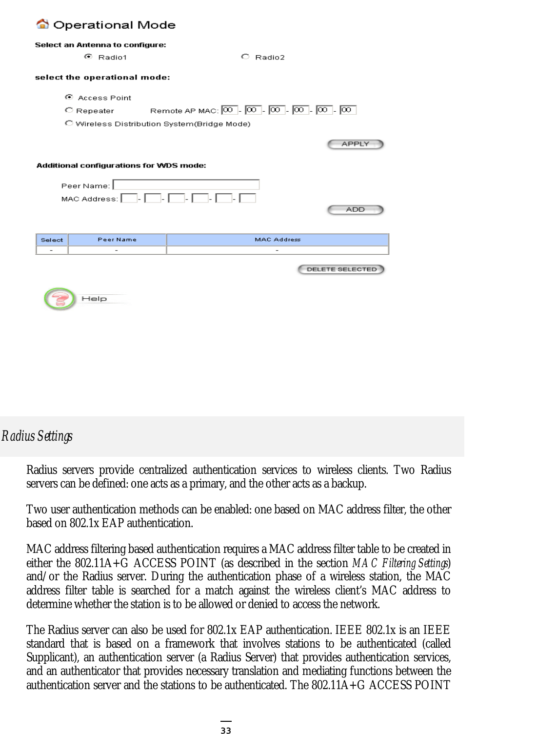
![For both ‘wpa-psk’ and ‘wpa’ types WPAEncryptionTypp: encryption protocol types (‘tkip’, ‘ccmp’, ‘both’). WPAGroupRekeyInterval: group key re-key interval (unit: sec). If ‘VLANState’ in [VLAN] is ‘enable’, the following items can be included: VLANID: the VLAN ID of the bridge that the SSID belongs to. VLANPriority: the 802.1p priority value of the packets came from the stations using the SSID. If ‘DiffServState’ in [DiffServ] is ‘enable’, the following item can be configured. DSCPValue: The DSCP value to be marked on each packet came from the stations using the SSID. [Radio1OperationMode] [Radio2OperationMode] OpMode=ap RepeaterMAC=00-11-22-33-00-55Operational Mode Configuration for Radio 1/2 OpMode: the operational mode setting (‘ap’ – WLAN Access Point only, ‘repeater’ – WLAN Access Point + Repeater, ‘wds’ – Internet Gateway + WLAN Access Point with WDS support). RepeaterMAC: if ‘OpMode’ is ‘repeater’, this item is required to configure the peer’s MAC address. [Radio1WDSEntry] [Radio2WDSEntry] WDSName=wds peer WDSMAC=00-11-22-33-44-55 WDS Entry Configuration for Radio 1/2 There could be multiple entries (max 8 entries), each entry contains the following items: WDSName: a mnemonic name for the peer. WDSMAC: the MAC address of the peer. [SystemManagement] HTTPPort=80 HTTPTimeout=10 TELNETPort=23 TELNETTimeout=10 WlanManagement=enable System Management Configuration HTTPPort: HTTP server port number. HTTPTimeout: idle time out value for a HTTP management session (unit: minute). TELNETPort: TELNET server port number. TELNETTimeout: idle time out value for a TELNET management session (unit: minute). WlanManagement: whether enable management from WLAN or not (‘enable’, ‘disable’). [UPNP] UPNPState=enable UPnP Configuration UPNPState: whether enable the UPnP function 57](https://usermanual.wiki/Wistron-NeWeb/CAP-1/User-Guide-422879-Page-57.png)
![(‘enable’, ‘disable’) [Syslog] SyslogLevel=3 SyslogState=disable SyslogState=enable SyslogdIP=102.2.2.2 Syslog Configuration SyslogLevel: syslog level, lower is severer and less events will be logged. SyslogState: whether enable the remote log function (‘enable’, ‘disable’). SyslogdIP: the IP address of the remote syslog daemon if ‘SyslogState’ is ‘enable’. [EmailLog] EmailLogState=enable EmailLogServer=sned.mail.com EmailLogMailAddr=user@recvmail.com Email Log Configuration EmailLogState: whether enable the Email Log function (‘enable’, ‘disable’). EmailLogServer: the domain name of the mail server for sending log mails EmailLogMailAddr: the Email address that the log mails will be sent to. [STP] STPState=disable STP (Spanning Tree Protocol) Configuration STPState: whether the STP function is enabled (‘enable’, ‘disable’). [SNMP] SnmpState=enable SysName=name SysLocation=Input System Location SysContact=Input Contact PersonReadCommunity=public WriteCommunity=private SNMP Configuration SnmpState: whether the SNMP function is enabled (‘enable’, ‘disable’). If ‘SnmpState’ is ‘enable’, the following items can be included: SysName: system name string. SysLocation: system location description. SysContact: system contact description. ReadCommunity: SNMP read-only community string.WriteCommunity: SNMP write community string. [TrapEntry] TrapManagerName=Sigma TrapManagerIP=192.168.1.9 TrapManagerState=enable SNMP Trap Manager Configuration There could be multiple entries (max 3 entries), each entry contains the following items: TrapManagerName: the mnemonic name for the trap manager. TrapManagerIP: the IP address of the trap manager. TrapManagerState: whether the trap manager is enabled (‘enable’, ‘disable’). 58](https://usermanual.wiki/Wistron-NeWeb/CAP-1/User-Guide-422879-Page-58.png)
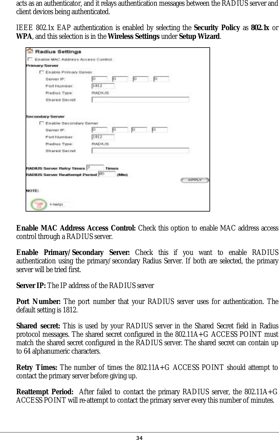
![[MACFilter] MACFilterPolicy =disable MAC Filter Configuration MACFilterPolicy: MAC Filter policy (‘disable’, ‘deny’, ‘grant’). [MACFilterEntry] MACFilterName=name MACFilterMAC=00-01-30-05-70-aa MAC Filter Entry Configuration There could be multiple entries (max 1024 entries), each entry contains the following items: MACFilterName: a mnemonic name for the entry. MACFilterMAC: the MAC address that the filter will be applied on. [RADIUS] RadiusRetryTimes=3 RadiusReattempPeriod=60 RadiusMACACLState=enable RADIUS Configuration RadiusRetryTimes: number of retries before giving up. RadiusReattempPeriod: re-attempt period (unit: minute). RadiusMACACLState: whether enable MAC address access control (‘enable’, ‘disable’) [PrimaryRADIUS] [SecondaryRADIUS] RadiusPrimaryState=enable RadiusPrimaryIP=1.1.1.1 RadiusPrimaryPort=1812 RadiusPrimarySharedSecret=1111 RadiusSecondaryState=enable RadiusSecondaryIP=2.2.2.2 RadiusSecondaryPort=1812 RadiusSecondarySharedSecret=2222 External Primary/Secondary RADIUS Server Configuration RadiusPrimaryState/RadiusSecondaryState: whether use the external primary/secondary RADIUS server (‘enable’, ‘disable’). If the ‘RadiusPrimaryState’/’RadiusSecondaryState’ is ‘enable’, the following items have to be configured: RadiusPrimaryIP/RadiusSecondaryIP: the IP address of the external primary/secondary RADIUS server. RadiusPrimaryPort/RadiusSecondaryPort: the port number on the external primary/secondary RADIUS server. RadiusPrimarySharedSecret/RadiusSecondarySharedSecret: the shared secret used for authentication with the external primary/secondary RADIUS server. [QOS] QOSState=enable QOSMapScheme=802.1p VLANPrio0=normal VLANPrio1=low VLANPrio2=low VLANPrio3=normal VLANPrio4=high QoS (Quality of Service) Configuration QOSState: whether enable the QoS function (‘enable’ or ‘disable’). QOSMapScheme: the QoS mapping scheme, when ‘VLANState’ in [VLAN] is ‘disable’, this must be ‘none’ (‘none’ – use the priority level configured, ‘802.1p’–use the 802.1p value and mapping 59](https://usermanual.wiki/Wistron-NeWeb/CAP-1/User-Guide-422879-Page-59.png)
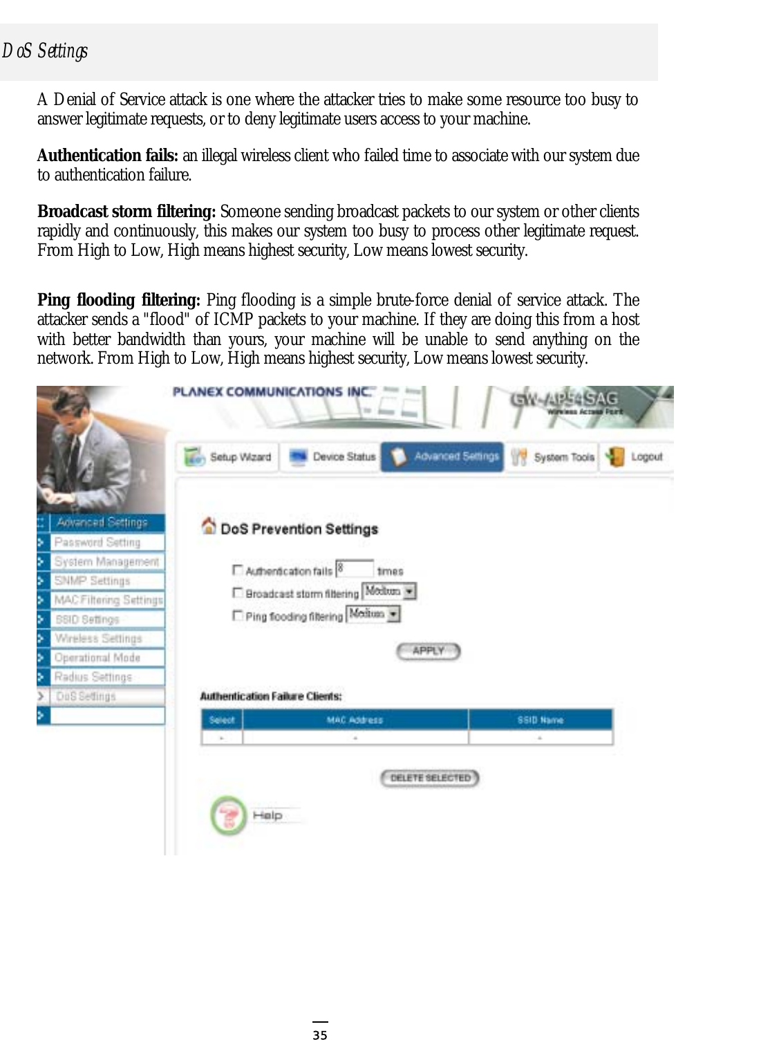
![VLANPrio5=high VLANPrio6=highest VLANPrio7=highest SchedulingScheme=htb HTBBwRatioHighest=10 HTBBwRatioHigh=20 HTBBwRatioNormal=40 HTBBwRatioLow=40 configured). VLANPrioi (i = 0, 1, 2, …, 7): the corresponding priority level for this VLAN 802.1p value (‘low’, ‘high’, ‘highest’). SchedulingScheme: the QoS scheduling scheme (‘sp’, ‘htb’). If ‘SchedulingScheme’ is ‘htb’, the following items could be configured: HTBBwRatioHighest/HTBBwRatioHigh/HTBBwRatioNormal/ HTBBwRatioNormal: the bandwidth percentage for the priority level highest/high/normal/low. [DOS] DOSAuthenticateState=enable DOSBroadcastState=enable DOSPingState=enable DOSAuthFailTimes=8 DOSBroadcastStormLevel=medium DOSPingFloodLevel=medium DoS (Denial of Service) Configuration DOSAuthenticateState: whether enable authentication failure attack (‘enable’, ‘disable’). DOSBroadcastState: whether enable broadcast storm prevention (‘enable’, ‘disable’). DOSPingState: whether enable ping flood prevention (‘enable’, ‘disable’). DOSAuthFailTimes: if ‘DOSAuthenticateState’ is ‘enable’, this items configures the number of failures that will put the client into the deny list. DOSBroadcastStormLevel: if ‘DOSBroadcastState’ is ‘enable’, this item configures the level of protection (‘high’, ‘medium’, ‘low’). DOSPingFloodLevel: if is ‘enable’, this item configures the level of protection (‘high’, ‘medium’, ‘low’). [End] This is a dummy section that must be put at the end of a text configuration file. There is no key and value in this section, and any line below this section will be ignored. 60](https://usermanual.wiki/Wistron-NeWeb/CAP-1/User-Guide-422879-Page-60.png)