Wistron NeWeb CAP-1 802.11 a+g Super A/G Intelligent WLAN Access Point User Manual for 802 11a g Access Point
Wistron NeWeb Corporation 802.11 a+g Super A/G Intelligent WLAN Access Point for 802 11a g Access Point
User Manual

IEEE 802.11a+g Access Point User’s Guide
IEEE 802.11A+G ACCESS POINT
User’s Guide
Version 1.0, April 2004
Page i

Copyright Statement
No part of this publication may be reproduced, stored in a retrieval system, or transmitted in
any form or by any means, whether electronic, mechanical, photocopying, recording or
otherwise without the prior writing of the publisher.
Windows™ 95/98/Me and Windows™ 2000/XP are trademarks of Microsoft® Corp.
Pentium is trademark of Intel.
All copyright reserved.
2

IEEE 802.11a+g Access Point User’s Guide
Table of Contents
Regulatory Information.............4
Introducing the 802.11A+G ACCESS POINT...5
Overview of the 802.11 a+g Access Point
...............................................................5
802.11A+G ACCESS POINT Features....6
Network Configuration Examples .........7
As An Access Point..........................7
As A stand-alone repeater...............8
As A point to multi-points Bridge ....8
Setting Up the device............................9
Static IP ...........................................9
Automatic IP....................................9
Installing the 802.11A+G ACCESS POINT.10
What’s in the Box?...............................10
Connecting the Cables ........................11
Configuration Steps Required for the 802.11A+G
ACCESS POINT ....................................11
Setting up a Windows PC or wireless client as
DHCP clients........................................12
A Look at the Front Panel....................14
Connecting More Devices Through A Hub To The
802.11A+G ACCESS POINT..................15
Basic Configuration of the 802.11A+G ACCESS
POINT ........................................................16
Logging On...........................................17
Setup Wizard........................................17
Time Settings.................................18
Device IP Settings .........................18
Wireless SETTINGS........................20
Advanced Settings....................................26
Password Settings...............................26
System Management .......................... 26
MAC Filtering Settings........................ 29
SSID Settings...................................... 30
Wireless Settings................................ 31
Operational Mode................................ 32
Radius Settings................................... 33
DoS Settings........................................ 35
Managing the 802.11A+G ACCESS POINT 36
How to View the device Status .......... 36
How to View the System Log.............. 37
Wireless Client Table.......................... 37
Bridge Table........................................ 38
Radio Table ......................................... 39
Upgrading Firmware ........................... 40
How to Save or Restore Configuration Changes
............................................................. 41
How to reset the configuration to the factory
default................................................. 42
How to Reboot your 802.11A+G ACCESS POINT
............................................................. 43
What if you Forgot the Password?...... 43
Command Line Interface .......................... 44
General guidelines.............................. 44
Express Mode vs. Advanced Mode of operation
............................................................. 45
Conventions ........................................ 45
List of Commands ............................... 46
Text Configuration.................................... 52
General guidelines.............................. 52
List of Sections................................... 52
Product Specification............................... 61

4
Regulatory Information
Federal Communication Commission Interference Statement
This equipment has been tested and found to comply with the limits for a Class B digital device,
pursuant to Part 15 of the FCC Rules. These limits are designed to provide reasonable protection
against harmful interference in a residential installation. This equipment generates, uses and can radiate
radio frequency energy and, if not installed and used in accordance with the instructions, may cause
harmful interference to radio communications. However, there is no guarantee that interference will
not occur in a particular installation. If this equipment does cause harmful interference to radio or
television reception, which can be determined by turning the equipment off and on, the user is
encouraged to try to correct the interference by one of the following measures:
- Reorient or relocate the receiving antenna.
- Increase the separation between the equipment and receiver.
- Connect the equipment into an outlet on a circuit different from that to which
the receiver is connected.
- Consult the dealer or an experienced radio/TV technician for help.
FCC Caution: To assure continued compliance, (example - use only shielded interface
cables when connecting to computer or peripheral devices) any changes or modifications
not expressly approved by the party responsible for compliance could void the user’s
authority to operate this equipment.
This device complies with Part 15 of the FCC Rules. Operation is subject to the following
two conditions: (1) This device may not cause harmful interference, and (2) this device
must accept any interference received, including interference that may cause undesired
operation.
IMPORTANT NOTE:
FCC Radiation Exposure Statement:
This equipment complies with FCC radiation exposure limits set forth for an uncontrolled
environment. This equipment should be installed and operated with minimum distance
20cm between the radiator & your body.
This transmitter must not be co-located or operating in conjunction with any other antenna or
transmitter.

Introducing the 802.11A+G ACCESS
POINT
Overview of the 802.11 a+g Access Point
The 802.11A+G ACCESS POINT is an access-point based on IEEE 802.11a+g based 2.4-
GHz and 5 GHz radio technology. It contains an 802.11a+g and a full-duplex 10/100 LAN
interfaces. The 802.11A+G ACCESS POINT can function as a simple Access Point (AP), and
act as the center point of a wireless network supporting a data rate of up to 54 Mbps. It can
also connect these wireless devices to wired network through the LAN interface.
The 802.11A+G ACCESS POINT can also function in a repeater mode, which is used to
extend the physical coverage of the wireless network. Finally, the 802.11A+G ACCESS
POINT can also function in a Wireless Distribution System (WDS) mode. Multiple
802.11A+G ACCESS POINT’s can be configured to operate in the WDS mode to inter-
connect wired LAN segments that are attached to these 802.11A+G ACCESS POINT’s.
Since the 802.11g shares the same 2.4GHz radio band as the 802.11b technology, it can inter-
operate with existing 11Mbps 802.11b devices. Therefore you can protect your existing
investment in 802.11b client cards, and migrate to the high-speed 802.11g standard as your
needs grow.
To address growing security concerns in a wireless LAN environment, different levels of
security can be enabled in the 802.11A+G ACCESS POINT, including:
• To disable SSID broadcast to restrict association to only those client stations that are already
pre-configured with the correct SSID
• To enable WEP (Wireless Encryption Protocol) 64, 128, or 152-bit encryption to protect
the privacy of your data.
• Support of Access List Control to allow you to grant/deny access to/from specified
wireless stations
• Provisioning of centralized authentication through Radius Server(s).
• WPA-PSK (Wi-Fi Protected Access, Pre-Shared Key) for home users to provide
authentication, data integrity, and data privacy.
• WPA (Wi-Fi Protected Access) works with a RADIUS server to provide stronger
authentication as well as data integrity and privacy.
Chapte
r
1

802.11A+G ACCESS POINT Features
Compliant with draft 802.11a, 802.11b and 802.11g standards with roaming
capability.
Support of the standard access point mode for connection to wireless clients.
Support of the repeater mode to extend infrastructure coverage.
Support of the WDS mode for interconnecting LAN segments.
Built-in DHCP Server to assign IP addresses to wired/wireless clients automatically.
Static assignment or DHCP client to set the device IP address.
Multiple security measures: SSID hiding, Access Control List, WEP based
encryption (64, 128, 152 bits), enhanced Security with 802.1x using a primary and a
backup Radius Server with/without dynamic WEP keys, WPA-PSK, and WPA.
Extensive monitoring capability such as event logging, traffic/error statistics
monitoring. Support of remote logging.
Easy configuration and monitoring through the use of a Web-browser based GUI,
SNMP commands from a remote SNMP management station, and UPnP for users
to automatically discover the device.
Setup Wizard for easy configuration/installation.
Configuration file download and restore.
Firmware upgradeable.
6
IEEE 802.11a+g Access Point User’s Guide
7
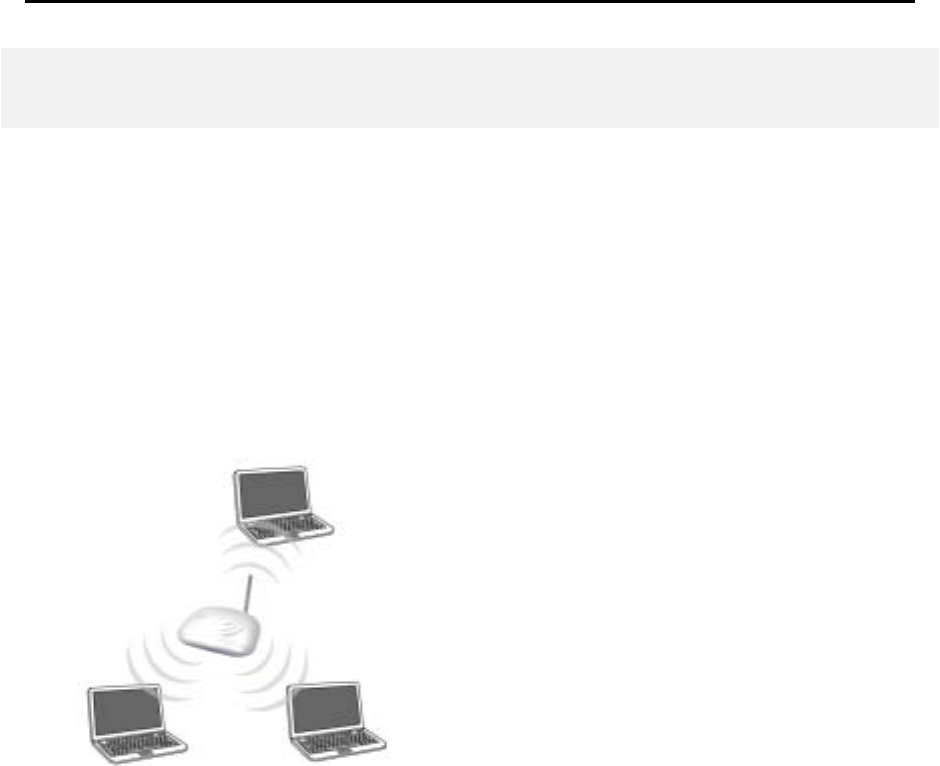
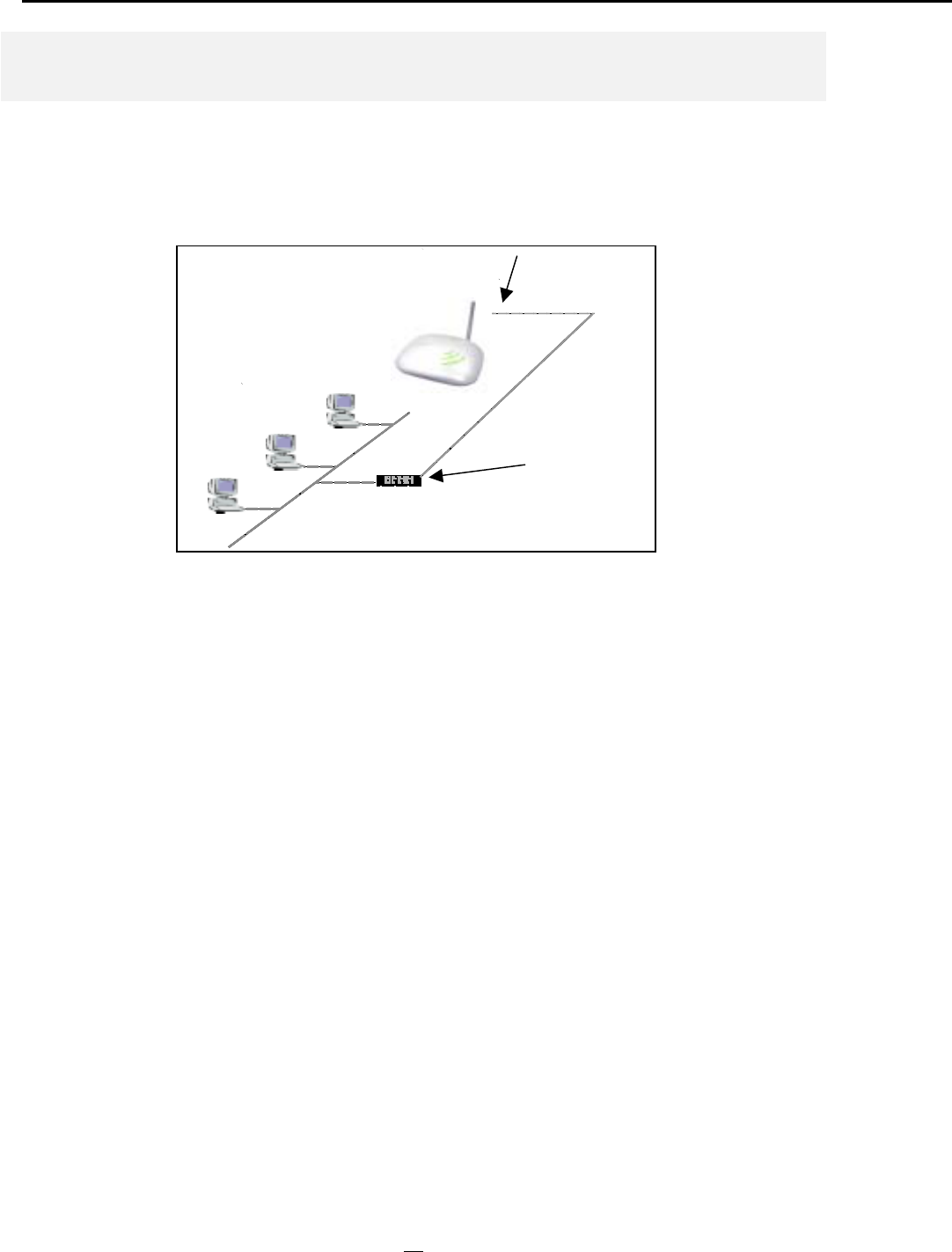
Network Configuration Examples
A group of wireless stations communicating with each other is called a Basic Service Set (BSS)
and is identified by a unique SSID.
When an 802.11A+G ACCESS POINT is used, it can be configured to operate in the
following three network configurations
AS AN ACCESS POINT
When configured in the Access Point mode, the 802.11A+G ACCESS POINT allows a group
of wireless stations to communicate with each other through it. Such a network is called an
Infrastructure BSS.
The 802.11A+G ACCESS POINT further provides bridging functions between the wireless
network and the wired LAN network.
When multiple access points are connected to the same LAN segment, stations can roam
from one 802.11A+G ACCESS POINT to another without losing their connections, as long
as they are using the same SSID. This is shown in the diagram below.
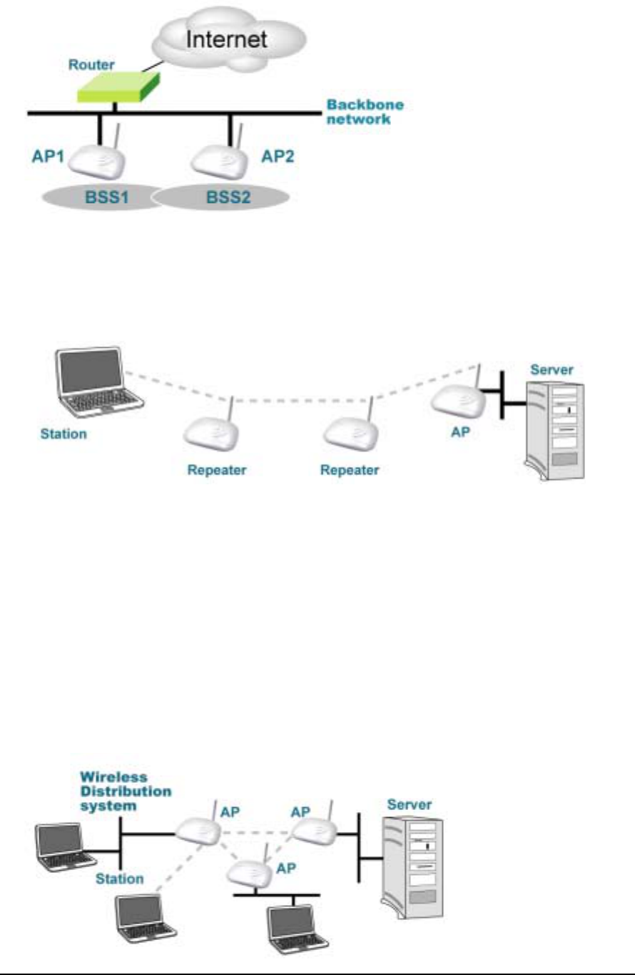
AS A STAND-ALONE REPEATER
The purpose of a repeater is to expand an existing infrastructure BSS. When configured to
operate in the Repeater Mode, the 802.11A+G ACCESS POINTs sit between wireless
stations and a “root” AP whose BSS is being expanded, as shown below:
AS A POINT TO MULTI-POINTS BRIDGE
When configured to operate in the Wireless Distribution System (WDS) Mode, the
802.11A+G ACCESS POINT provides bridging functions between the LAN behind it and
separate LANs behind other AP’s operating in the WDS mode. The system will support up to
eight such AP’s in a WDS configuration.
Note that an 802.11A+G ACCESS POINT running in the WDS mode can also support
wireless stations simultaneously, as shown in the left most AP in the diagram below:
8

IEEE 802.11a+g Access Point User’s Guide
9
Setting Up the device
The 802.11A+G ACCESS POINT can be managed remotely by a PC through either the
wired or wireless network. To do this, the 802.11A+G ACCESS POINT must first be
assigned an IP address, which can be done using one of the following two methods.
STATIC IP
The default IP address of the LAN interface of an 802.11A+G ACCESS POINT is a private IP
address of 192.168.1.1, and a network mask of 255.255.255.0. This means IP addresses of other
devices on the LAN should be in the range of 192.168.1.2 to 192.168.1.254.
This IP address can be modified to either a different address in this same subnet or to an
address in a different subnet, depending on the existing netwrok settings (if there is any) or
user’s preference.
AUTOMATIC IP
The 802.11A+G ACCESS POINT can also be configured to “obtain” an IP address
automatically from a DHCP server on the network. This address is called “dynamic” because
it is only dynamically assigned to the device, which may change depending on the IP assignment
policy used by the DHCP server on the network. Since the IP address in this case may change
from time to time, this method is not recommended - unless the user uses UPnP or other
management tools that do not depend on a fixed IP address.

Chapte
r
2
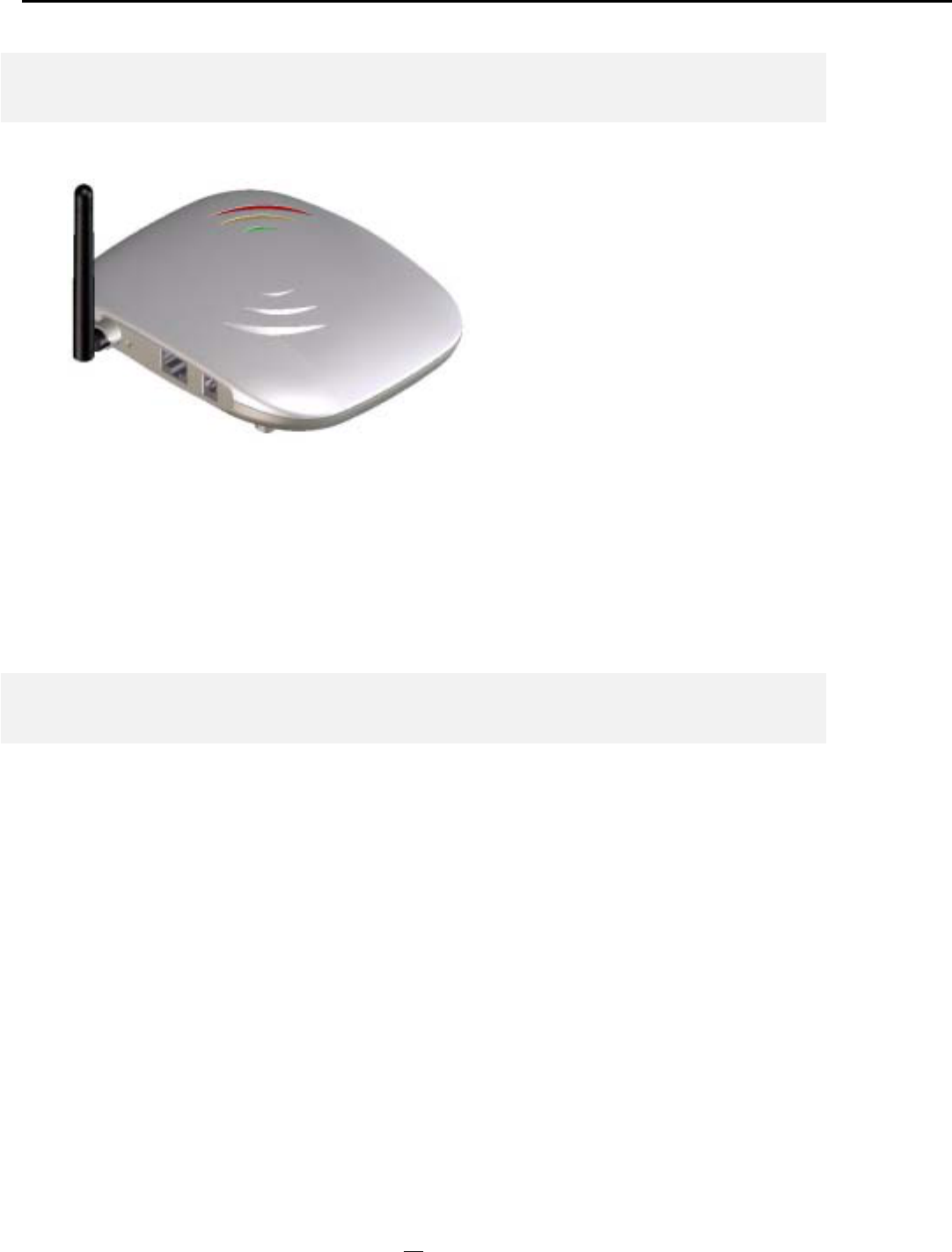
Installing the 802.11A+G ACCESS POINT
This section describes the installation procedure for the 802.11A+G ACCESS POINT. It
starts with a summary of the content of the package you have purchased, followed by steps of
how to power up and connect the 802.11A+G ACCESS POINT. Finally, this section
explains how to configure a Windows PC to communicate with the 802.11A+G ACCESS
POINT.
What’s in the Box?
The 802.11A+G ACCESS POINT package contains the following items:
One 802.11A+G ACCESS POINT
One 5V AC power adapter with a barrel connector
CD of the 802.11A+G ACCESS POINT User’ Guide
Connecting the Cables
The Back Panel of the 802.11A+G ACCESS POINT appears as follows:
Follow these steps to install your 802.11A+G ACCESS POINT:
Step 1.
Step 2.
Connect a LAN hub to the LAN port on the 802.11A+G ACCESS POINT
using the supplied LAN cable.
Connect the power adapter to an electrical outlet and the 802.11A+G ACCESS
POINT.
Configuration Steps Required for the 802.11A+G ACCESS POINT
This section describes configuration required for the 802.11A+G ACCESS POINT before it
can work properly in your network.
First, it is assumed that in your LAN environment, a separate DHCP server will be available
for assigning dynamic (and often private) IP addresses to requesting DHCP clients. This
means that the 802.11A+G ACCESS POINT normally will not need to enable the DHCP
server function.
Additionally, since you need to perform various configuration changes to the 802.11A+G
ACCESS POINT, including the SSID, Channel number, the WEP key, …, etc., it is necessary
to associate a fixed IP address with the 802.11A+G ACCESS POINT, which is why the
802.11A+G ACCESS POINT will be shipped with a factory default private IP address of
192.168.1.1 (and a network mask of 255.255.255.0).
Therefore, during the system installation time, you need to build an isolated environment with
the 802.11A+G ACCESS POINT and a PC, and then perform the following steps:
Manually change the IP address of the PC to become 192.168.1.3
11

Connect the PC to the 802.11A+G ACCESS POINT and change its configuration to a static
IP address based on your network environment. For example, if there is a DHCP server that
assigns IP addresses from the range 192.168.23.10 - 192.168.23.254 to DHCP client devices, it
can reserve 192.168.23.10 for the 802.11A+G ACCESS POINT and then the address pool
with the DHCP server becomes 192.168.23.11 – 192.168.23.254.
If there is no DHCP server on your network environment, you just have to make sure that
there is no machine in the environment has the same IP address as another machine.
Please note that after you change the IP address of the ACCESS POINT, the PC client may
not be able to reach the ACCESS POINT. This is because they may no longer belong to the
same IP network address space.
Change the setting of the PC back to “obtain IP addresses dynamically”.
Now you can put the 802.11A+G ACCESS POINT and the PC to your network where the
DHCP server is connected. From then on, any wireless client configured to “obtain IP
addresses dynamically” will work with the AP, with each other, and with devices on the wired
LAN network.
Setting up a Windows PC or wireless client as DHCP clients
The following will give detailed steps of how to configure a PC or a wireless client to “obtain
IP addresses automatically”. For other types of configuration, please refer to the
corresponding user manual.
In the case of using a LAN attached PC, the PC must have an Ethernet interface installed
properly, be connected to the 802.11A+G ACCESS POINT either directly or through an
external LAN switch, and have TCP/IP installed and configured to obtain an IP address
automatically from a DHCP server in the network.
In the case of using a wireless client, the client must also have an 802.11a/b/g wireless
interface installed properly, be physically within the radio range of the 802.11A+G ACCESS
POINT, and have TCP/IP installed and configured to obtain an IP address automatically
from a DHCP server in the network.
Then perform the following steps for either of the cases above. To configure types of
workstations other than Windows 95/98/NT/2000/XP, please consult the manufacturer’s
documentation.
Step 1.
Step 2.
Step 3.
From the Win95/98/2000 Start Button, select Settings, then
Control Panel. The Win95/98/2000/XP Control Panel
displays.
Double-click on the Network icon.
Check your list of Network Components in the Network
window Configuration tab. If TCP/IP has already been
i
n
stalled gotoStep8 O
therwise select Add to install it now
12

installed, go to Step 8. Otherwise, select Add to install it now.
Step 4.
Step 5.
Step 6.
Step 7.
In the new Network Component Type window, select
Protocol.
In the new Select Network Protocol window, select
Microsoft in the Manufacturers area.
In the Network Protocols area of the same window, select
TCP/IP, then click OK. You may need your Win95/98 CD
to complete the installation. After TCP/IP installation is
complete, go back to the Network window shown in Step 4.
Select TCP/IP in the list of Network Components.
Click Properties, and check the settings in each of the TCP/IP
Properties window:
Bindings Tab: both Client for Microsoft Networks and File
and printer sharing for Microsoft Networks should be
selected.
Gateway Tab: All fields should be blank.
DNS Configuration Tab: Disable DNS should be selected.
IP Address Tab: Obtain IP address automatically should be
selected.
Step 8. With the 802.11A+G ACCESS POINT powered on, reboot
the PC/wireless client. After the PC/wireless client is re-
booted, you should be ready to configure the 802.11A+G
ACCESS POINT. See Chapter 3.
The procedure required to set a static IP address is not too much different from the procedure
required to set to “obtain IP addresses dynamically” - except that at the end of step 7, instead
of selecting “obtain IP addresses dynamically, you should specify the IP address explicitly.
13
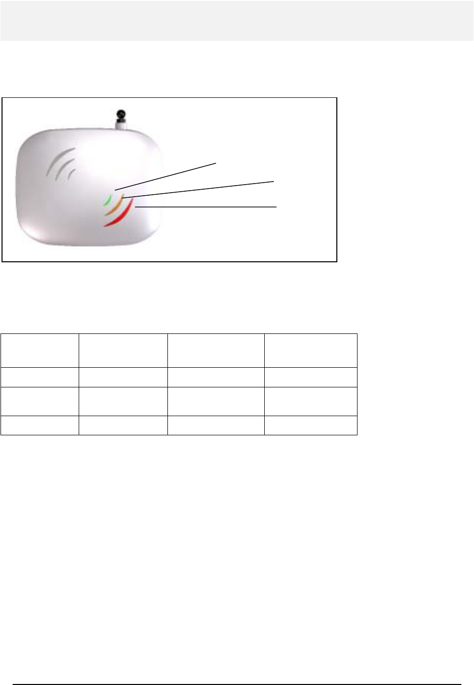
A Look at the Front Panel
The LEDs on the front of the 802.11A+G ACCESS POINT reflect the operational status of
the unit. The status of the LAN, the wireless, and power can be monitored from this display.
Wireless
LAN
Power
802.11A+G ACCESS POINT LED Description
Label Wireless LAN POWER
Steady Light Link is active Link is active Power
OFF No Wireless
connection No LAN connection No Power
FLASH XMT/RCV Data XMT/RCV Data N/A
14
Connecting More Devices Through A Hub To The 802.11A+G ACCESS POINT
The 802.11A+G ACCESS POINT provides an RJ45 LAN interface that you can use to
connect to a PC or an external hub.
Step 1.
Plug this end into
any port of an
Ethernet
hub/switch
Connect to the
LAN port
15
Basic Configuration of the 802.11A+G ACCESS POINT
This section describes the basic configuration procedure for the 802.11A+G ACCESS
POINT. It describes how to set up the 802.11A+G ACCESS POINT for wireless
connections, and the configuration of the local LAN environment.
The 802.11A+G ACCESS POINT is designed so that all basic configuration may be effected
through the a standard Web browser such as Microsoft Internet Explorer.
From a PC that has been configured as described in Chapter 2, enter the IP address of the
802.11A+G ACCESS POINT as the URL in your browser, e.g. http://192.168.1.1.
Note: The IP address of your PC must be in the same IP subnet as the 802.11A+G ACCESS POINT.
Chapte
r
3
16
The Home Page of the 802.11A+G ACCESS POINT screen will appear, with its main menu
displayed on the right hand side of the window. The main menu includes the following choices:
Setup Wizard, Device Status, Advanced Settings, System Tools, and Help; these can be used to
navigate to other menus.
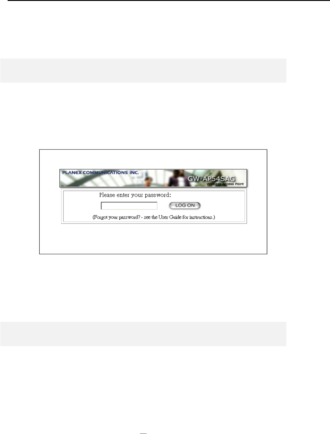
Logging On
If you attempt to access a configuration item from the browser menu, an administrator login
screen will appear, prompting you for the password in order to log on.
If you are logging on for the first time, you should use the factory default setting “password”.
The password is always displayed as a string of asterisks (“*”). Click the LOG ON button to
start the configuration session.
Setup Wizard
The Setup Wizard will guide you through a series of configuration screens to set up the basic
functionality of the device. After you finish these screens, press the “finish” button on the last
screen to make all your modifications effective.
17
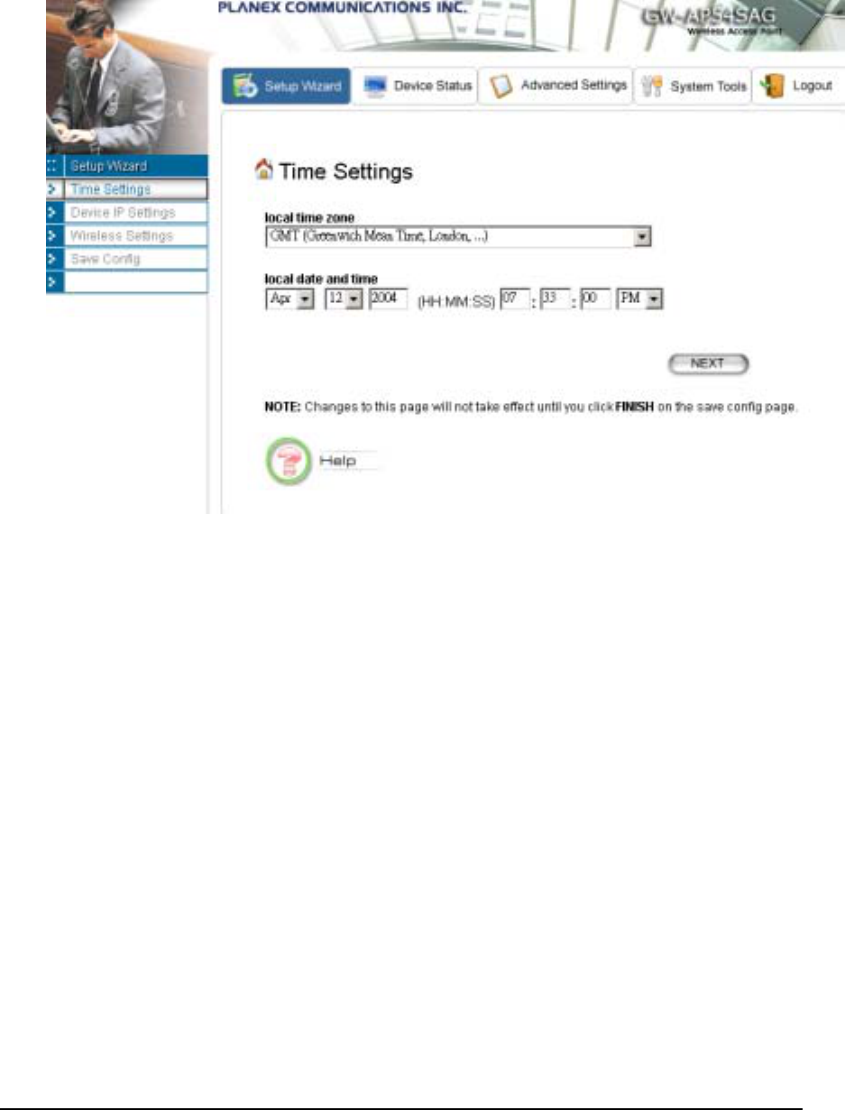
TIME SETTINGS
After logging in, the time settings page appears. The device time is automatically set to the
local time of the management PC at the first time a connection is made. To modify the
device’s time, modify the appropriate fields, then click NEXT.
DEVICE IP SETTINGS
18
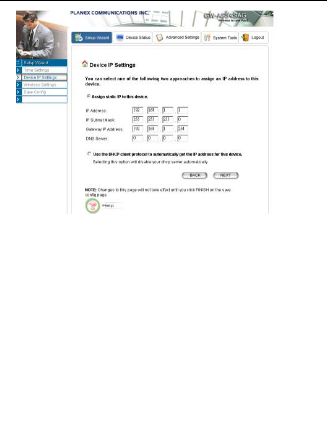
The Device IP setting screen allows you to configure the IP address and subnet of the device.
Although you can rely on a DHCP server to assign an IP address to the 802.11A+G ACCESS
POINT automatically, it is recommended that you configure a static IP address manually in
most applications.
If you choose to assign the IP address manually, check the button that says “Assign static IP
to this device” and then fill in the following fields
IP Address and IP Subnet Mask: These values default to 192.168.1.1 and 255.255.255.0,
respectively. It is important to note that there are similar addresses falling in the standard private
IP address range and it is an essential security feature of the device. Because of this private IP
address, the device can no longer be accessed (seen) from the Internet.
Gateway IP Address: Enter the IP address of your default gateway
DNS Server: The Domain Name System (DNS) is a server on the Internet that translates
logical names such as “www.yahoo.com” to IP addresses like 66.218.71.80. In order to do this,
a query is made by the requesting device to a DNS server to provide the necessary information.
If your system administrator requires you to manually enter the DNS Server addresses, you
should enter them here.
Click Next to go to the next screen.
19
If you choose to use a DHCP Server to acquire an IP address for the 802.11A+G Access
Point automatically, check the button that says, “Use the DHCP protocol to automatically
get the IP address for this device”. Then click Next to go to the next screen. Again, as a
reminder, it is recommended that your 802.11A+G ACCESS POINT should be assigned a
static IP address in order to make it easy for you to manage the device later on.
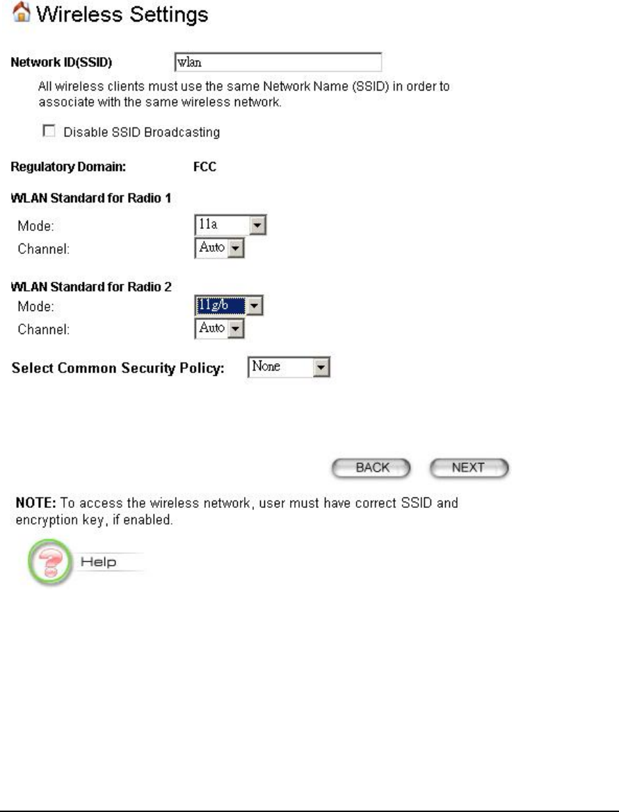
WIRELESS SETTINGS
Network Name (SSID): The SSID is the network name used to identify a wireless network. The
SSID must be the same for all devices in the wireless network (i.e. in the same BSS). Several access
points on a network can have the same SSID. The SSID length is up to 32 characters. The default
SSID is “wlan”.
20

Disable SSID Broadcasting: An access point periodically broadcasts its SSID along with other
information, which allows client stations to learn its existence while searching for access points in a
wireless network. Check Disable if you do not want the device to broadcast the SSID.
WLAN mode: The wireless module is IEEE 802.11g and 802.11b compliant, and choosing
“11g/b” allows both 802.11b and 802.11g client stations to get associated. 802.11g However,
choosing “11g” allows only 802.11g client stations to get associated and get better overall
performance. 802.11a is not compliant with either 802.11b or 802.11g; choosing “11a” only allows
802.11a client stations to get associated, 802.11a turbo, 802.11g turbo, super a without turbo,
super g without turbo, super a with dynamic turbo, super g with dynamic turbo or super a
with static turbo, super g with static turbo protocol (the turbo mode is only applied where the
regulation allows). The same explanation for both of the radios.
Regulatory Domain: Please make sure that your regulatory domain matches your region. The
default value is FCC. For most regions, FCC may be the better choice.
Channel: Select a channel from the available list to use. All devices in a BSS must use the
same channel. You can select Auto to let the system pick up the best channel for you.
Note: The available channels are different from country to
country and for different WLAN mode.
Security Policy: You can select different security policy to provide association authentication
and/or data encryption.
WEP
21
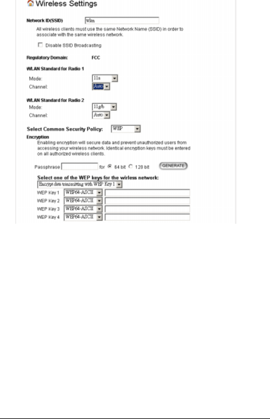
WEP allows you to use data encryption to secure your data from being eavesdropped by
malicious people. It allows 3 types of key: 64 (WEP64), 128 (WEP128), and 152 (WEP152)
bits. You can configure up to 4 keys using either ASCII or Hexadecimal format.
Key Settings: The length of a WEP64 key must be equal to 5 bytes, a WEP128 key is 13
bytes, and a WEP152 key is 16 bytes. For WEP64 and WEP128, you can just enter a pass-
phrase and click the GENERATE button to generate the four keys. So you can use a
mnemonic string as the pass-phrase instead of memorizing the four keys.
Key Index: You have to specify which of the four keys will be active.
Once you enable the WEP function, please make sure that both the 802.11A+G ACCESS
POINT and the wireless client stations use the same key.
Note: Some wireless client cards only allow Hexadecimal digits for WEP keys. Please note
that when configuring WEP keys, a WEP128 ASCII key looks like “This is a key”(13
characters), while a WEP128 Hex key looks like “54-68-69-73-20-69-73-20-61-20-6b-65-
79”(13 bytes).
802.1x
22
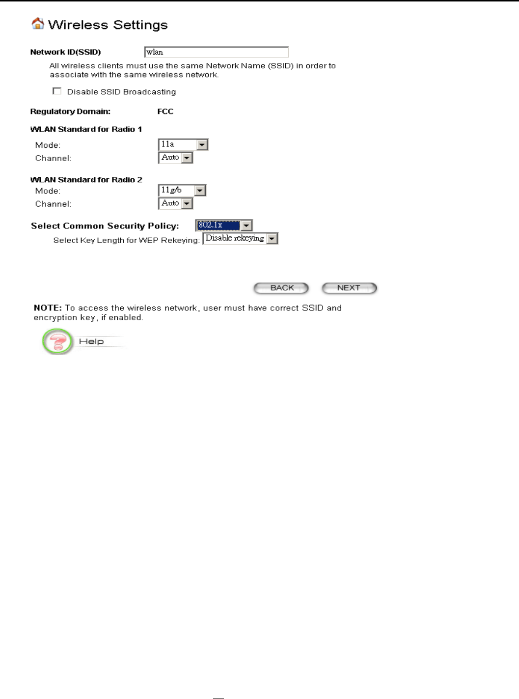
802.1x allows users to leverage a RADIUS server to do association authentications. You can
also enable dynamic WEP keys (64, 128, 152-bit) to have data encryption. Here you do not
have to enter the WEP key manually because it will be generated automatically and dynamically.
NOTE: After you have finished the configuration wizard, you have
to configure the Radius Settings in Advanced Settings in order to
make the 802.1x function work.
WPA-PSK
23
Wi-Fi Protected Access (WPA) with Pre-Shared Key (PSK) provides better security than WEP
keys. It does not require a RADIUS server in order to provide association authentication, but
you do have to enter a shared key for the authentication purpose. The encryption key is
generated automatically and dynamically.
Pre-shared Key: This is an ASCII string with 8 to 63 characters. Please make sure that both
the 802.11A+G ACCESS POINT and the wireless client stations use the same key.
Encryption Type: There are two encryption types TKIP and CCMP (AES). While CCMP
provides better security than TKIP, some wireless client stations may not be equipped with the
hardware to support it. You can select Both to allow TKIP clients and CCMP clients to
connect to the Access Point at the same time.
Group Rekey Interval: A group key is used for multicast/broadcast data, and the rekey
interval is time period that the system will change the group key periodically. The shorter the
interval is, the better the security is. 60 seconds is a reasonable time, and it is used by default.
WPA
24
Wi-Fi Protected Access (WPA) requires a RADIUS server available in order to do
authentication (same as 802.1x), thus there is no shared key required.
The Encryption Type and Group Rekey Interval settings are same as WPA-PSK.
Finish Setup Wizard and Save Your Settings
After stepping through the Wizard’s pages, you can press the FINISH button for your
modification to take effect. This also makes your new settings saved into the permanent memory on
your system.
25
Congratulations! You are now ready to use the 802.11A+G ACCESS POINT.
Note: If you change the device’s IP address, as soon as you click on FINISH you will no longer be able
to communicate with your 802.11A+G ACCESS POINT. You need to change your IP address and then
re-boot your computer in order to resume the communication.
Advanced Settings
The advanced settings tab on the top row of the window allows you to perform modifications
that normally you may not need to do for general operations except changing your password
from the default factory setting (this is highly recommended for security purposes).
Password Settings
The default factory password is “password”. To change the password, press the Password
Settings button to enter the Password Settings screen, then enter the current password
followed by the new password twice. The entered characters will appear as asterisks.
System Management
26
Clicking the System Management button to configure system related parameters to for the
802.11A+G ACCESS POINT.
Management Utility Port Definition: The standard port settings for the HTTP Web server
and the Telnet utility may be replaced by entering new port numbers in these fields.
Management Session Time-out: This setting specifies the duration of idle time (inactivity)
before a web browser or telnet management session times out. The default time-out value is
10 minutes.
Local Management: The local management feature allows you to manage your 802.11a+g
Access Point locally through the use of an HTTP browser.
System Administration: The Access Point allows you to designate special port numbers
other than the standard 80 for http for remote management. It also allows you to specify the
duration of idle time (inactivity) before a web browser session times out. The default time-out
value is 10 minutes.
UPnP: The Universal Plug and Play (UPnP) feature allows a Windows XP/ME PC to
discover this 802.11A+G Access Point and automatically show an icon on the screen. Then a
user can double-click the icon to access this device directly (without having to find out its IP
address).
27
Bridge: You can enable/disable the 802.1d STP (Spanning Tree Protocol) function on the
bridge of WLAN and Ethernet (i.e. the LAN interface). Enable this function can detect loops
in your LAN environment and then protect the LAN from being saturated with infinite loop
traffic.
Syslog: Syslog is an IETF (Internet Engineering Task Force - the Internet standards body)-
conformant standard for logging system events (RFC-3164). When the 802.11A+G ACCESS
POINT encounters an error or warning condition (e.g., a log-in attempt with an invalid
password), it will create a log in the system log table. To be able to remotely view such system
log events, you need to check the Enable Syslog box and configure the IP address of a Syslog
daemon. When doing so, the 802.11A+G ACCESS POINT will send logged events over
network to the daemon for future reviewing.
Syslog server IP address: The IP address of the PC where the Syslog daemon is running.
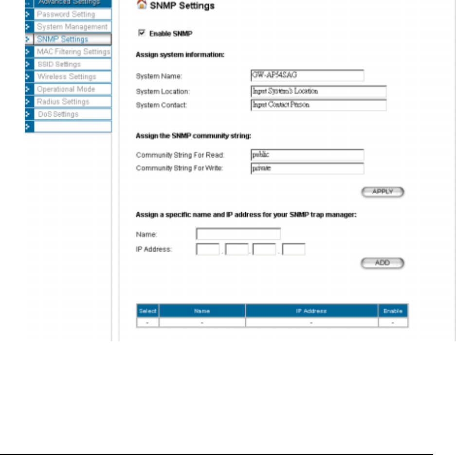
System Name: A name that you assign to your 802.11a+g Access Point. It is an
alphanumeric string of up to 30 characters.
28

System Location: Description of where your 802.11a+g Access Point is physically located. It
is an alphanumeric string of up to 60 characters.
System Contact: Contact information for the system administrator responsible for managing
your 802.11a+g Access Point. It is an alphanumeric string of up to 60 characters.
Community String For Read: If you intend the access point to be managed from a remote
SNMP management station, you need to configure a read-only “community string” for read-
only operation. The community string is an alphanumeric string of up to 15 characters.
Community String For Write: For read-write operation, you need to configure a write
“community string”.
A trap manager is a remote SNMP management station where special SNMP trap messages
are generated (by the Access Point) and sent to in the network.
You can define trap managers in the system.
You can add a trap manager by entering a name, an IP address, followed by pressing the
ADD button.
You can delete a trap manager by selecting the corresponding entry and press the DELETE
SELECTED button.
You enable a trap manager by checking the Enable box in the corresponding entry or disable
the trap manager by un-checking the Enable box.
MAC Filtering Settings
The 802.11A+G ACCESS POINT allows you to define a list of MAC addresses that are
allowed or denied to access the wireless network
Disable MAC address control list: When selected, no MAC address filtering will be
performed.
Enable GRANT address control list: When selected, data traffic from only the specified
devices in the table will be allowed in the network.
Enable DENY address control list: When selected, data traffic from the devices specified in
the table will be denied/discarded by the network.
29
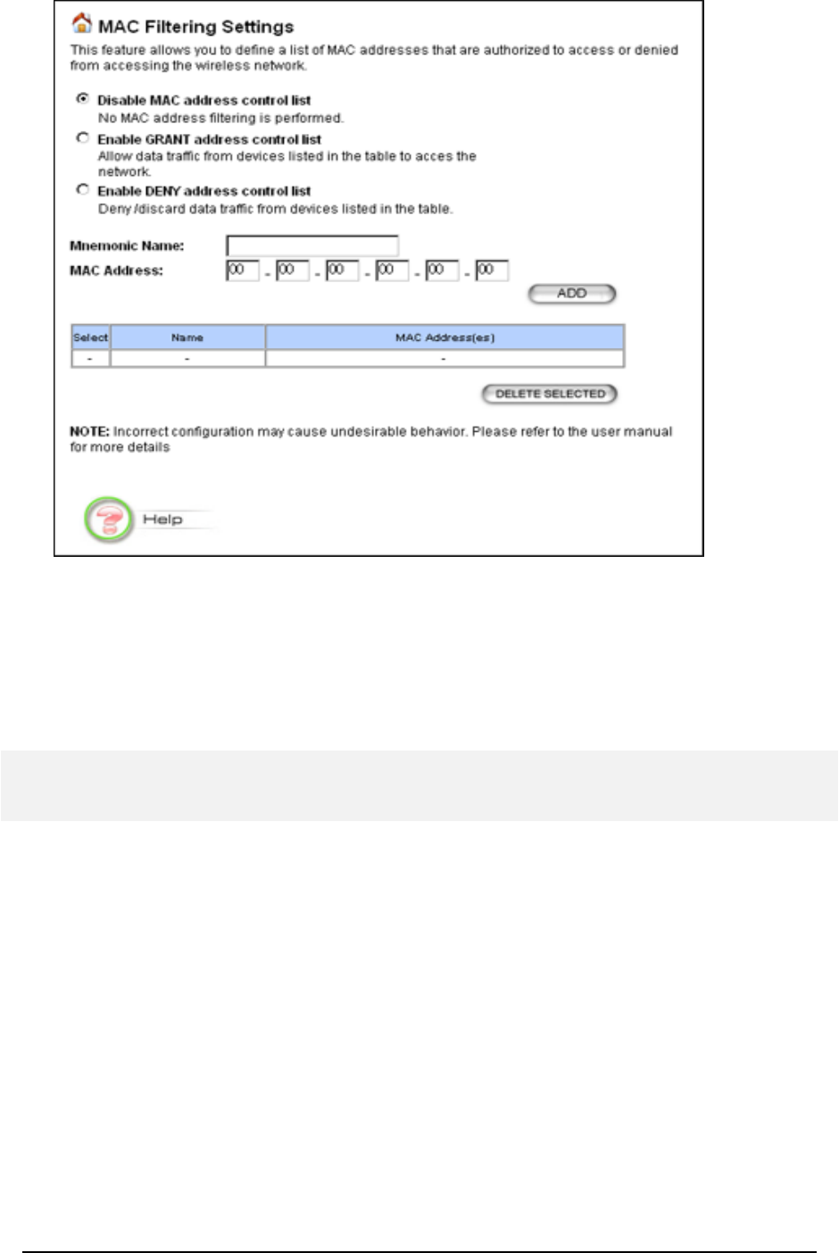
To add a MAC address into the table, enter a mnemonic name and the MAC address, then
click ADD.
The table lists all configured MAC Filter entries. To delete entries, check the corresponding
select boxes and then press DELETE SELECTED
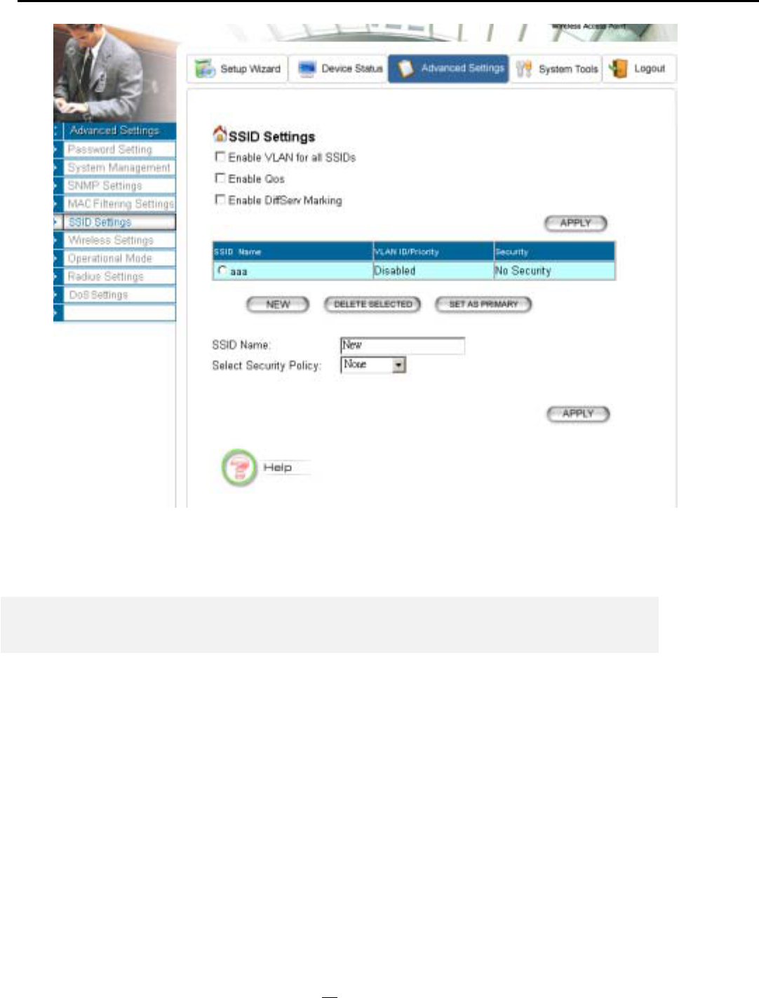
SSID Settings
The Access Point can allow user to set up different SSID settings - Enable VLAN, QoS or
DiffServ QoS. Each this SSID setting is based on which Security Policy.
30
Wireless Settings
Beacon Interval: The 802.11A+G ACCESS POINT broadcasts beacon frames regularly to
announce its existence. The beacon Interval specifies how often beacon frames are transmitted
- in time unit of milliseconds. The default value is 100, and a valid value should be between 1
and 65,535.
RTS Threshold: RTS/CTS frames are used to gain control of the medium for transmission.
Any unicast (data or control) frames larger than specified RTS threshold must be transmitted
following the RTS/CTS handshake exchange mechanism. The RTS threshold should have a
value between 256-2347 bytes, with a default of 2347. It is recommended that this value does
not deviate from the default too much.
Fragmentation Threshold: When the size of a unicast frame exceeds the fragmentation
threshold, it will be fragmented before the transmission. It should have a value of 256-2346
bytes, with a default of 2346. If you experience a high packet error rate, you should slightly
decrease the Fragmentation Threshold.
31
DTIM Interval: The 802.11A+G ACCESS POINT buffers packets for stations that operate
in the power-saving mode. The Delivery Traffic Indication Message (DTIM) informs such
power-conserving stations that there are packets waiting to be received by them. The DTIM
interval specifies how often the beacon frame should contain DTIMs. It should have a value
between 1 to 255, with a default value of 3.
User Limitation: Input what’s the maximum users can connect with Access Point through
SSID. The default value is 100.
Enable privacy separator for 2 radio: enable/disable.
Radio 1/Radio 2 Transmit Power: 100%, 75%, 50%, 25%, 12%.
Operational Mode
The 802.11A+G ACCESS POINT can be configured to operate in one of the following three
modes as mentioned previously in Chapter 1:
(1) Access Point (2) Repeater (3) Wireless Distribution System (WDS)
When configured as a WDS, you need to further configure the name and MAC address of its
peer WDS devices.
32

Radius Settings
Radius servers provide centralized authentication services to wireless clients. Two Radius
servers can be defined: one acts as a primary, and the other acts as a backup.
Two user authentication methods can be enabled: one based on MAC address filter, the other
based on 802.1x EAP authentication.
MAC address filtering based authentication requires a MAC address filter table to be created in
either the 802.11A+G ACCESS POINT (as described in the section MAC Filtering Settings)
and/or the Radius server. During the authentication phase of a wireless station, the MAC
address filter table is searched for a match against the wireless client’s MAC address to
determine whether the station is to be allowed or denied to access the network.
The Radius server can also be used for 802.1x EAP authentication. IEEE 802.1x is an IEEE
standard that is based on a framework that involves stations to be authenticated (called
Supplicant), an authentication server (a Radius Server) that provides authentication services,
and an authenticator that provides necessary translation and mediating functions between the
authentication server and the stations to be authenticated. The 802.11A+G ACCESS POINT
33
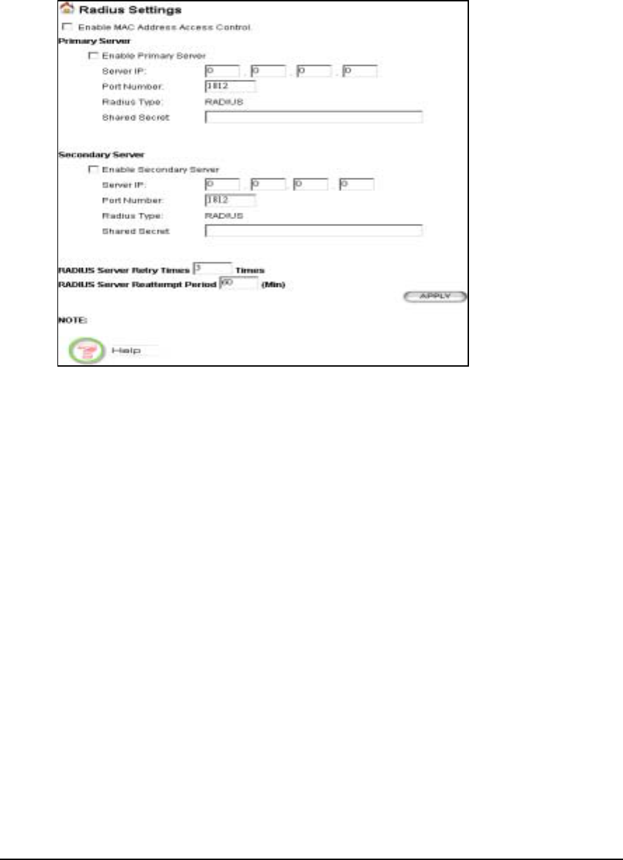
acts as an authenticator, and it relays authentication messages between the RADIUS server and
client devices being authenticated.
IEEE 802.1x EAP authentication is enabled by selecting the Security Policy as 802.1x or
WPA, and this selection is in the Wireless Settings under Setup Wizard.
Enable MAC Address Access Control: Check this option to enable MAC address access
control through a RADIUS server.
Enable Primary/Secondary Server: Check this if you want to enable RADIUS
authentication using the primary/secondary Radius Server. If both are selected, the primary
server will be tried first.
Server IP: The IP address of the RADIUS server
Port Number: The port number that your RADIUS server uses for authentication. The
default setting is 1812.
Shared secret: This is used by your RADIUS server in the Shared Secret field in Radius
protocol messages. The shared secret configured in the 802.11A+G ACCESS POINT must
match the shared secret configured in the RADIUS server. The shared secret can contain up
to 64 alphanumeric characters.
Retry Times: The number of times the 802.11A+G ACCESS POINT should attempt to
contact the primary server before giving up.
Reattempt Period: After failed to contact the primary RADIUS server, the 802.11A+G
ACCESS POINT will re-attempt to contact the primary server every this number of minutes.
34
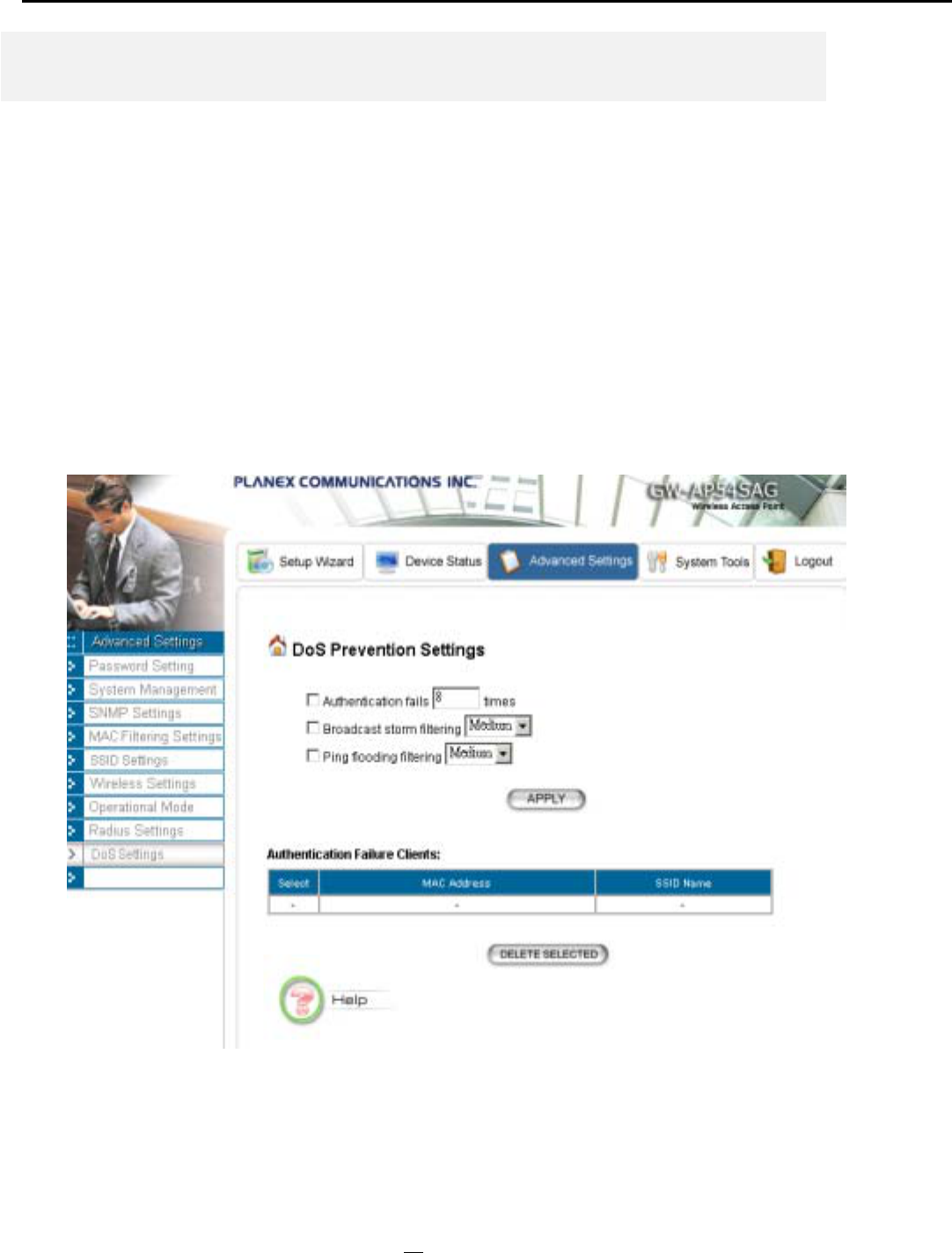
DoS Settings
A Denial of Service attack is one where the attacker tries to make some resource too busy to
answer legitimate requests, or to deny legitimate users access to your machine.
Authentication fails: an illegal wireless client who failed time to associate with our system due
to authentication failure.
Broadcast storm filtering: Someone sending broadcast packets to our system or other clients
rapidly and continuously, this makes our system too busy to process other legitimate request.
From High to Low, High means highest security, Low means lowest security.
Ping flooding filtering: Ping flooding is a simple brute-force denial of service attack. The
attacker sends a "flood" of ICMP packets to your machine. If they are doing this from a host
with better bandwidth than yours, your machine will be unable to send anything on the
network. From High to Low, High means highest security, Low means lowest security.
35
Chapte
r
4
Managing the 802.11A+G ACCESS POINT
This Chapter covers other management aspects of your 802.11A+G ACCESS POINT:
How to view the device status
How to view the system log
How to upgrade the firmware of your 802.11A+G ACCESS POINT
How to save or restore configuration changes
How to reset the configuration to the factory default.
How to reboot your 802.11A+G ACCESS POINT
What if you forgot the password
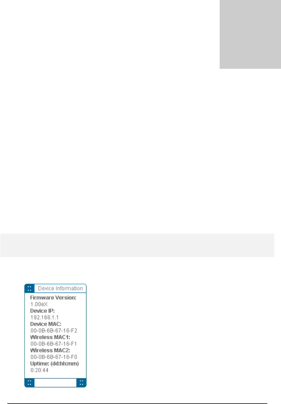
How to View the device Status
You can monitor the system status and get general device information from the Device
Information screen:
36
This is at the left-bottom corner of the Device Status window.
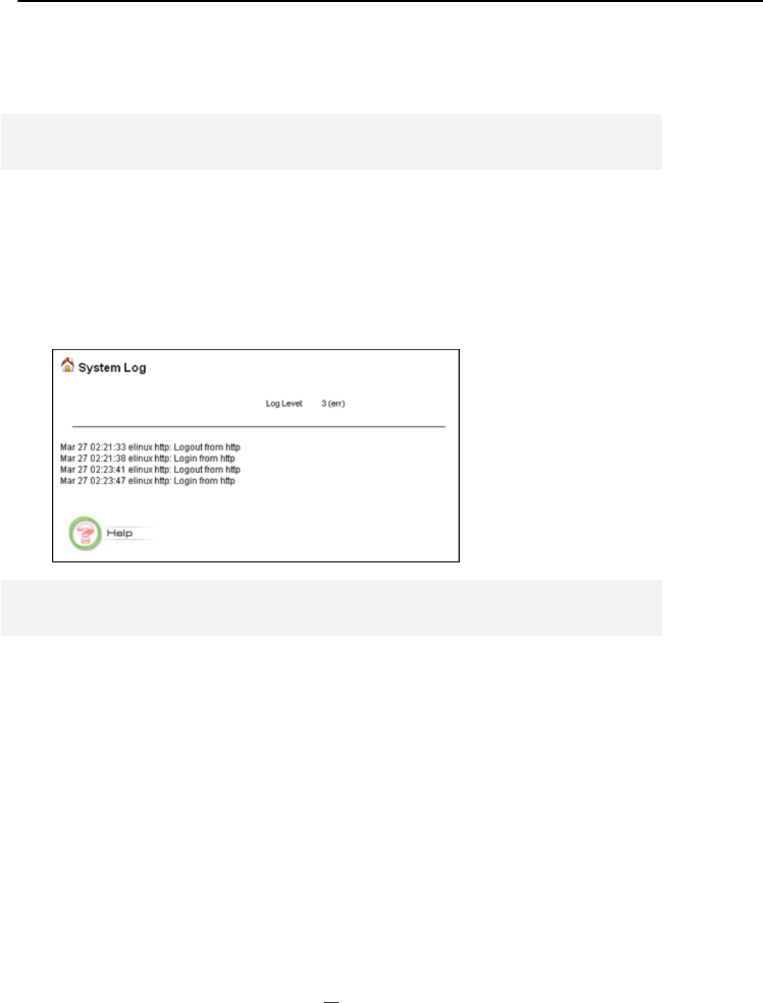
How to View the System Log
The 802.11A+G ACCESS POINT maintains a system log that you can use to track events
that have occurred in the system. Such event messages can sometimes be helpful in
determining the cause of a problem that you may have encountered.
You can select System Log on the left side of the Device Status window to view log events
recorded in the system. The System Log entries are shown in the main screen along with the
log level, the severity level of messages that are being displayed (lower is severer), and the
uptime, which is the amount of time since the 802.11A+G ACCESS POINT was boot-up.
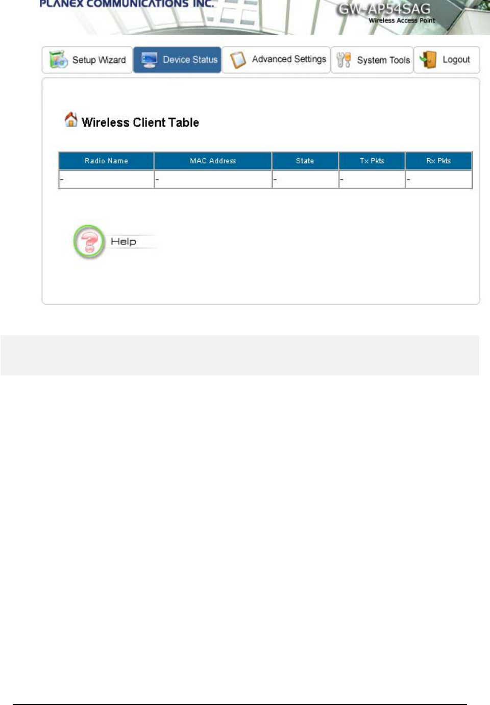
Wireless Client Table
The wireless client table lists the current wireless clients and its MAC address, state, and traffic
statistics. You can check this table by clicking Wireless Client Table at the left side of the
Device Status window.
37
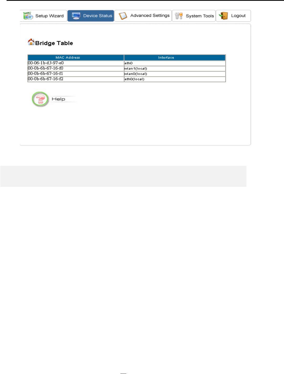
Bridge Table
The bridge table shows all MAC entries learned from the wired LAN interface, wireless clients,
and WDS peers (if running in the WDS mode). You can check this table by clicking Bridge
Table at the left side of the Device Status window.
38
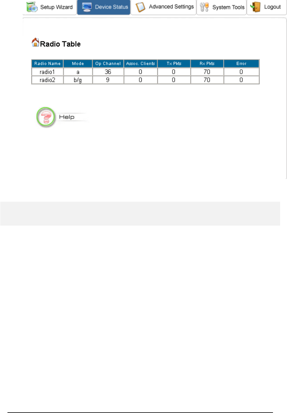
Radio Table
Radio table lists current Mode, channel, client associated with them and transmit packet,
received packet, data error.
39
Upgrading Firmware
You can upgrade the firmware of your 802.11A+G ACCESS POINT (the software that
controls your 802.11A+G ACCESS POINT’s operation). Normally, this is done when a new
version of firmware offers new features that you want, or solves problems that you have
encountered with the current version. System upgrade can be performed through the System
Upgrade window as follows:
Step 1 Select System Tools, then Firmware Upgrade from the menu and the following
screen displays:
40
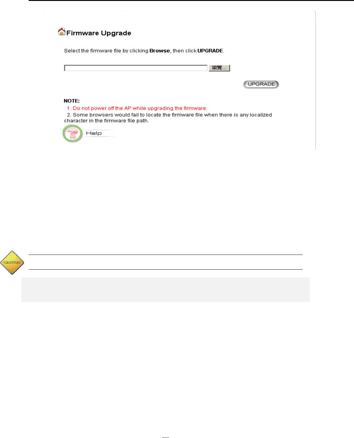
Step 2 To update the 802.11A+G ACCESS POINT firmware, first download the firmware
from the distributor’s web site to your local disk, and then from the above screen enter the
path and filename of the firmware file (or click Browse to locate the firmware file). Next, Click
the Upgrade button to start.
The new firmware will begin being loaded to your 802.11A+G ACCESS POINT. After a
message appears telling you that the operation is completed, you need to reset the system to
have the new firmware take effect.
Note: It is recommended that you do not upgrade your 802.11A+G ACCESS POINT unless the new
firmware contains a new feature that you want or if it contains a fix to a problem that you’ve encountered.
How to Save or Restore Configuration Changes
You can save system configuration settings to a file, and later download it back to the
802.11A+G ACCESS POINT by following the steps below.
Step 1 Select Configuration Save and Restore from the System Tools menu and you will
see the following screen:
41
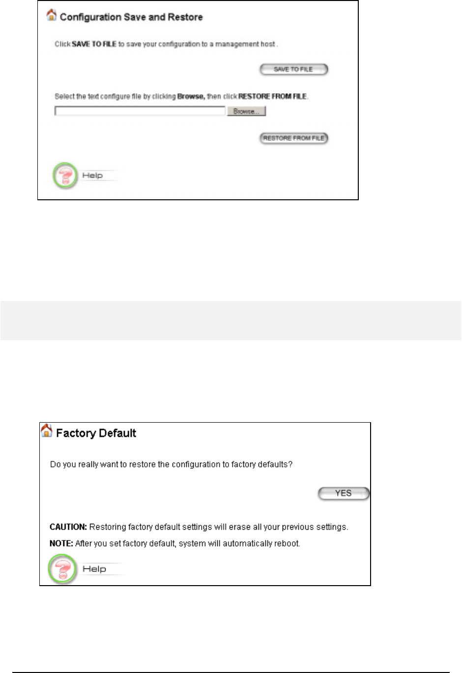
Step 2 Enter the path of the configuration file to save-to/restore-from (or click the Browse
button to locate the configuration file). Then click the SAVE TO FILE button to save the
current configuration into the specified file, or click the RESTORE FROM FILE button to
restore the system configuration from the specified file.
How to reset the configuration to the factory default
You can reset the configuration of your 802.11A+G ACCESS POINT to the factory default
settings. To do it:
Step 1 Select Factory Default from the System Tools menu, you will see the following
screen:
Step 2 Click YES to go ahead and restore the configuration to the factory default.
42
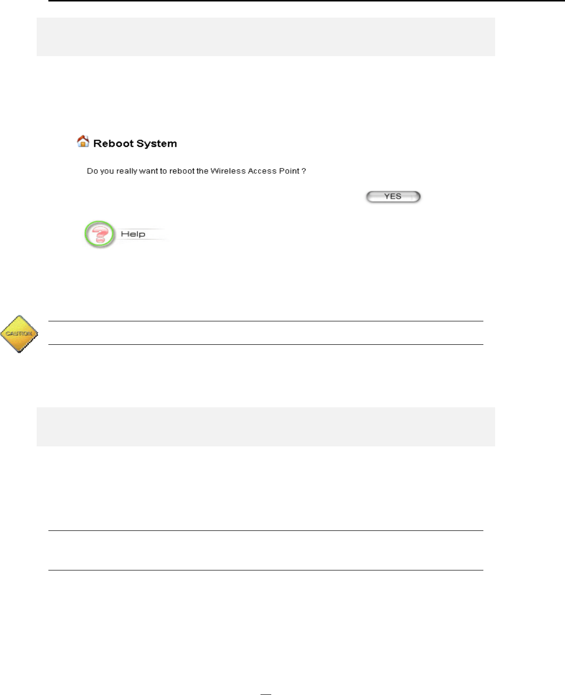
How to Reboot your 802.11A+G ACCESS POINT
You can reset your 802.11A+G ACCESS POINT from the Browser. To reset it:
Step 1 Select Reboot System from the System Tools menu, you will see the following
screen:
Step 2 Click YES to reboot the 802.11A+G ACCESS POINT.
Note: Resetting the 802.11A+G ACCESS POINT disconnects any active clients, and therefore will
disrupt any current data traffic.
What if you Forgot the Password?
If you forgot the password, the only way to recover is to clear the device configuration and
return the unit to its original state as shipped from the factory. You can do this by pressing the
hardware “restore” button on the back of the device and hold for two seconds. Please note
that this will also clear your current configuration and restore the configuration from the
factory default.
43

C
h
apte
r
5
Command Line Interface
This chapter describes the Command Line Interface (CLI) for the 802.11 a+g Access Point. The
CLI is accessible through a Telnet session.
General guidelines
When the 802.11 a+g Access Point is powered up, the user can use a standard telnet application
from a PC connected to the network to perform configuration and management functions. This is
done by typing the telnet command, “telnet <the 802.11 a+g Access Point’s ip>” (the default is
192.168.1.1) and pressing a return key, the user will see a system sign-on message followed by a
password prompt as follows.
Wireless AP Manager Console <rev_no>
please enter your password:
A default password “password” has been pre-configured with the system. The user should use it to
log into the system until the password is explicitly changed using the
change password
command.
Note that the entered password is case-sensitive. This password may also be changed using the
browser-based GUI configuration utility.
The password entered will be echoed back as asterisks (*). After the Carriage Return is entered, if
the password string is validated, the command prompt
Command>
will be displayed, and the user
can then issue other commands. Otherwise, the password prompt will be redisplayed.
Most commands are single-line commands, and commands are not context sensitive: each
command is independent of other commands before or after it.
The command syntax is straightforward.
The following briefly summarizes the guideline for the interface.
At any time, the user can type a “?” (preceded by a space) to request context-sensitive help
on what the user can enter next.
At any time, the user can type control-p (^p, by pressing both the Ctrl key and the p key at
the same time) to repeat the previous command, or control n to return to the following
(next) command. At startup, typing ^p or ^n will not cause anything to happen - since
previous commands do not yet exist. In normal operation, typing ^p will cause the
previous command to show, and the cursor will sit at the end of the command. At this
point, the user can either type a carriage return to accept the command, or type backspaces
44

to edit the command from the end. Up to 15 previously entered commands can be
invoked through ^p’s and ^n’s.
If a keyword is expected when the user types “ ?”, all valid keywords will be displayed. The
command typed in so far will then be displayed again along with the cursor sitting at the
end, waiting for the user to continue.
If the user types in part of the keyword but does not type in the entire word, the user can
then enter a tab or space for the system to automatically complete the keyword if the
characters typed in so far can uniquely identify the keyword. If the characters typed in so
far do not uniquely identify a keyword, a list of possible keywords will be displayed.
If the user is not sure what to type next, he or she can type "?” to display the possible
keywords that match the current CLI command input.
If an interactive mode is entered, the system will prompt for each required parameter, such as:
…
Command> add radius server primary
enter server IP (Unspecified): 192.168.1.10
enter port number (1812, 1-65535): 1812
enter shared secret:
…
The first prompt means current IP setting is not specified yet, and there is no default for that.
The second prompt means a number between 1 and 65535 is expected, with 1812 being the
default.
During the first time a particular parameter is configured, typing a carriage return will cause the
default value to be selected. Otherwise, typing a carriage return means no change to the
current value.
Express Mode vs. Advanced Mode of operation
The Command Line Interface operates in one of two modes:
Express
Mode
or
Advanced
Mode
. In Express Mode, not all parameters are displayed. Default values are set for those
parameters not displayed in multi-line commands. In Advanced Mode, users have the option
to modify all possible values appropriate to each operation.
The user can toggle between Express Mode and Advanced Mode by typing ^E (Control-E) at
any time. Normally, the system prompt will be changed by appending “>>” to the configured
prompt when in Advanced Mode.
Conventions
The following notations will be used:
lan means the LAN port;
45

wlan means the Wireless port;
<> specifies the arguments of the command, <1-4> means a number between 1 to 4;
[ ] indicates an optional parameter
| is used to separate alternative choices of parameters or keywords;
{} encloses all alternative keywords;
MacAddr, or XX-XX-XX-XX-XX-XX means any MAC address in hexadecimal
format, where each XX can be 00, 01, ... 99, 0A, 0B, 0C, 0D, 0E, 0F, 10, 11,… FF;
ipAddr, netmask, or xxx.xxx.xxx.xxx means any ip address or network mask, where
xxx is a decimal integer between 0 and 255;
The term string means a string of characters up to the specified length, which may be
enclosed in double quotes (“) (required if the string contains embedded blanks);
Names representing filters and MAC addresses could be up to 30 characters in length;
password and SNMP community read/write strings are up to 15 characters in length.
When the password and SNMP community write string are entered, they are echoed
back as a string of “*”s for protection, while other parameters, such as WEP keys, are
echoed back the way they are typed (in clear text).
List of Commands
From a functional point of view, CLI commands will be grouped into the following categories:
(1) System
(2) Filtering
(3) SNMP
(4) Diagnostics
(5) Security
The command format will be described in the following sections.
(1) System Commands
clear config
Description: Reset the system configuration to the factory default.
disable upnp
Description: Disable the UPnP function.
disable wlan management
46

Description: Disable the management function from a WLAN connected user.
enable upnp
Description: Enable the UPnP function.
enable wlan management
Description: Enable the management function from a WLAN connected user.
help
Description: Show help descriptions on CLI.
logout
Description: Logout the current CLI management session.
ping <IP address>
Description: Show help descriptions on CLI.
reset system
Description: Reboot the system. Any configuration not saved (e.g. by “save config”) will be lost.
save config
Description: Save the current configuration onto the flash, so the configuration will be kept after the
system is rebooted.
set http port <port number, 1-65535>
Description: Set the HTTP server port (for device management) to the one specified.
set http timeout <timeout value in minutes, 1-60>
Description: Set the timeout value for the HTTP management session.
set prompt <string up to 15 characters>
Description: Set the command line prompt.
set system contact <string up to 60 characters>
Description: Configure a string describing the system contact information. This is the value of the
SNMP system contact MIB.
set system ip
47

Description: Set the IP address for the device LAN interface.
set system location <string up to 60 characters>
Description: Configure a string describing the system location information. This is the value of the
SNMP system location MIB.
set system name <string up to 30 characters>
Description: Configuring a string for the system name. This is also the value of the SNMP system
name MIB.
set telnet port <port number, 1-65535>
Description: Set the TELNET server port (for device management) to the one specified.
set telnet timeout <timeout value in minutes, 1-60>
Description: Set the timeout value for a TELNET management session.
show arp table
Description: Display the ARP table of the system.
show http
Description: Display the current configurations of the HTTP management function.
show system
Description: Display the current basic system configurations.
show system ip
Description: Display the current device IP settings of the system.
show telnet
Description: Display the current configurations of the TELNET management function.
show upnp
Description: Display the current configurations of the UPnP function.
show wlan management
Description: Display the current state of WLAN management.
(2) Filtering Commands
add mac filter <string up to 30 characters> <MAC address, XX-XX-XX-XX-XX-XX>
48

Description: Add a MAC filter with the specified name (a mnemonic name) and MAC address.
delete mac filter <string up to 30 characters>
Description: Delete the MAC filter with the specified name.
set mac filter mode <MAC filter mode, disabled/grant/deny>
Description: Set the MAC filter mode.
show mac filter [<string up to 30 characters>]
Description: Display the MAC filter entry with the specified name. If no name is specified, this
command display all currently configured MAC filter entries.
show mac filter mode
Description: Display the currently configured MAC filter mode.
(3) SNMP Commands
disable snmp
Description: Disable the SNMP function.
enable snmp
Description: Enable the SNMP function.
set community string {read | write} <string up to 15 characters>
Description: Configure the SNMP READ/WRITE community string.
show community string read
Description: Display the SNMP READ community string.
show snmp
Description: Display the current SNMP settings.
show snmp statistics
Description: Display the current SNMP statistics.
show trap manager [<string up to 30 characters>]
Description: Display the settings of the specified SNMP trap manager. If no trap manager is
specified, this command displays the settings of all trap managers.
49

(4) Diagnostics Commands
disable log <facility>
Description: Disable the log function on the specified facility.
disable syslogd
Description: Disable the remote log function.
disable trace <facility>
Description: Disable the trace function on the specified facility.
enable log <facility> [<log level, 1-7>]
Description: Enable the log function with the specified log level on the specified facility. If no log
level is specified, the previously configured log level is used.
enable syslogd
Description: Enable the remote log function.
enable trace <facility> [<log level, 1-7>]
Description: Enable the trace function with the specified log level on the specified facility. If no log
level is specified, the previously configured log level is used.
set log level <log level, 1-7>
Description: Set the log level.
set syslogd <IP address>
Description: Configure the IP address of the remote syslog daemon. This is used for the remote
syslog function.
show log level
Description: Display the current log level.
show log table [<facility>]
Description: Display the current logged events of the specified facility. If no facility is specified, this
command displays all logged events.
show syslogd
Description: Display the current configuration of the remote log function.
(5) Security Commands
add radius server {primary | secondary}
50

Description: Configure the primary/secondary RADIUS server settings. This is a multi-line
command, and you have to enter the IP address and port number of the server, shared secret, and
enable/disable.
change password
Description: Change the password for management, including HTTP and TELNET.
disable radius mac authentication
Description: Disable the use of external RADIUS servers for MAC address access control.
disable radius server {primary | secondary}
Description: Disable the use of the primary/secondary RADIUS server.
enable radius mac authentication
Description: Enable the use of external RADIUS servers for MAC address access control.
enable radius server {primary | secondary}
Description: Enable the use of the primary/secondary RADIUS server.
set radius server reattempt <reattempt interval in minutes, 5-60>
Description: Configure the reattempt time for the system to contact the primary RADIUS server
after the primary RADIUS server was down.
set radius server retry <retry interval in times, 1-5>
Description: Configure the number of retries after which the system may think the RADIUS server
is down.
show radius server [{primary | secondary}]
Description: Display the configuration of the specified RADIUS server. If no server is specified, this
command displays the configurations of all RADIUS servers.
51

Text Configuration
The text configuration provides another way for users to configure the 802.11 a+g Access Point.
Users can save the system current configuration onto a file on PC, edit the configuration file, and
then restore the system configuration with the configuration file. For details regarding the save and
restore configuration operations, please read the HOW TO SAVE OR RESTORE CONFIGURATION
CHANGES section in the MANAGING YOUR 802.11A+G Access Point chapter. This chapter
describes the syntax and semantics of a text configuration file.
General guidelines
The format of a text configuration file is like the Microsoft Window® INI (extension file
name: .ini) file format. The basic file structure can be divided into the following parts:
1. Sections
A section name is enclosed in square brackets, alone on a line. Section names are allowed
to contain any character but square brackets or linefeeds. For example: “[sectionName]”.
Basically a section corresponds to a configuration item, a section contains zero or more key
and value pairs that are the settings for the configuration item. A section name is case
insensitive.
2. Keys and Values
A section contains zero or more key and value pairs, declared with the syntax “key =
value”. A key is a string without space and the value consists of all characters at the right
hand side of the equal sign. That is, a key starts with the first non-blank ASCII character at
the right hand side of an equal sign and extends to a comment mark (if there is one) or the
end of the line. So blanks are allowed among non-blank characters. A key string is case
insensitive.
3. Comments
A comment starts with a semicolon or a hash sign and extends to the end of the line.
List of Sections
Section & Examples Description
C
h
apte
r
6
52

[Manufacture]
Version = 1.00
This is used by the system itself, and this should be
put as the first section in a configuration file. Users
should not modify anything in this section.
[Password]
Password=000000
Password: the password for system management.
[Time]
TimeZone = +09:00
System Time Configuration
TimeZone: the time zone of the system. Possible
values are -12:00, -11:00, -10:00, …, +00:00,
+01:00, …, +13:00.
[Device]
IPType=static
IPAddress=192.168.1.1
IPNetmask=255.255.255.0
GatewayIP=192.168.1.254
DNSIP=168.95.1.3
IPType=dhcp
Device IP Configuration
IPType: the device IP type (‘static’ or ‘dhcp’)
For ‘static’ type:
IPAddress/IPNetmask: the IP address and network
mask of the device.
GatewayIP: the IP address of the default gateway.
DNSIP: the IP address of the DNS.
[ISP]
ISPType=static
ISPStaticIP=100.0.0.1
ISPNetmask=255.255.0.0
ISPGateway=100.0.0.2
ISPDNSIP=123.0.0.1
ISPType=dhcp
Hostname=name
ISPType=pppoe
PPPoEUserName=name
PPPOEPassword=password
PPPOEServiceName=service
PPPOEConnectionType=demand
_dialing
PPPOEMTU=1492
PPPOEMRU=1492
PPPOESessionType=normal
PPPOESessionType=unnumbere
d_link
KeepPrivateLan=enable/disable
UnnumberedIP=192.168.1.1
UnnumberedNetmask=255.255.2
55.0
WAN Interface Configuration
ISPType: the WAN connection type (‘static’, ‘dhcp’,
‘pppoe’, ‘pptp’).
For ‘static’ type:
ISPStaticIP: the IP address assigned by ISP.
ISPNetmask: the netmask assigned by ISP.
ISPGateway: the default gateway address assigned by
ISP.
ISPDNSIP: the DNS server address assigned by ISP.
For ‘dhcp’ type:
Hostname: the host name (if any) assigned by your
ISP.
For ‘pppoe’ type:
PPPoEUserName: user name of the ISP account
PPPOEPassword: password for the ISP account
PPPOEServiceName: service name for the
connection
PPPOEConnectionType: type of the PPP connection
(‘demand_dialing’, ‘always_on’, ‘manually’).
PPPOEMTU/PPPOEMRU: the MTU/MRU for the
connection (unit: byte).
PPPOESessionType: type of the PPPoE session
(‘normal’, ‘multiple_pppoe’, ‘unnumbered_link’).
53

ISPType=pptp
PPTPLocalIP=11.0.0.10
PPTPNetmask=255.255.255.0
PPTPRemoteIP=11.0.0.1
PPTPUserName=name
PPTPPassword=password
PPTPIdleTimeout=time
For PPPoE ‘unnumbered_link’ session type:
KeepPrivateLan: keep the private LAN or not
(‘enable’ or ‘disable’).
UnnumberedIP: the IP address of the private LAN if
‘KeepPrivateLan’ is ‘enable’
UnnumberedNetmask: the subnet mask of the private
LAN if ‘KeepPrivateLan’ is ‘enable’
For ‘pptp’ type:
PPTPLocalIP: the local IP address for establishing
the PPTP tunnel.
PPTPNetmask: the subnet mask of the WAN
interface where the PPTP tunnel is established.
PPTPRemoteIP: the remote IP address for
establishing the PPTP tunnel.
PPTPUserName: the user name of the ISP account.
PPTPPassword: the password name of the ISP
account.
PPTPIdleTimeout: the maximum idle time before the
connection is taken down (unit: minute).
[MultiplePPPoEEntry]
MpppoeSessionName=session
name
MpppoeUserName=name
MpppoePassword=password
MpppoeConnectionType=manual
ly
MpppoeMTU=1492
MpppoeMRU=1492
MpppoeLanType=enable
MpppoeLanIP=2.2.0.0
MpppoeLanNetmask=255.255.0.0
TPIPRange=enable
TPPortRange=disable
TPKeyword=disable
TPNetBios=enable
TPRuleIPRange=50.0.0.0-20
TPRuleNetwork=60.0.0.0/24
TPRulePortRange=40000-50000
TPRuleKeyword=key pattern
Multiple PPPoE Sessions Configuration
There could be multiple entries (max 7 entries), each
entry contains the following items:
MpppoeSessionName: a mnemonic name for this
entry.
MpppoeUserName: the user name for the ISP
account.
MpppoePassword: the password for the ISP account.
MpppoeConnectionType: type of the PPP
connection (‘demand_dialing’, ‘always_on’,
‘manually’).
MpppoeMTU/MpppoeMRU: the MTU/MRU for
the connection (unit: byte).
MpppoeLanType: Enable the LAN type access on
the session or not (‘enable’ or ‘disable’)
MpppoeLanIP: the IP address of the LAN type
network if ‘MpppoeLanType’ is ‘enable’.
MpppoeLanNetmask: the subnet mask of the LAN
type network if ‘MpppoeLanType’ is ‘enable’.
TPIPRange: whether enable IP address range and
network traffic pattern on the session (‘enable’,
‘disable’).
TPPortRange: whether enable port range traffic
pattern on the session (‘enable’, ‘disable’).
TPKeyword: whether enable keyword traffic pattern
on the session (‘enable’, ‘disable’).
54

TPNetBios: whether enable NetBIOS traffic pattern
on the session (‘enable’, ‘disable’).
The following items can appear more than one in a
multiple PPPoE entry:
TPRuleIPRange: specify an IP address range traffic
pattern.
TPRuleNetwork: specify an IP network traffic
pattern.
TPRulePortRange: specify a port range traffic
pattern.
TPRuleKeyword: specify a keyword traffic pattern.
[CloneMAC]
CloneMACState=disable
CloneMAC=00-01-02-03-04-05
Clone MAC Configuration
CloneMACState: whether enable the clone MAC
function (‘disable’, ‘enable’).
CloneMAC: the MAC address to be cloned.
[Radio]
SSIDBoradcast=enable
Radio1Mode=11a
Radio1Channel=auto
Radio2Mode=11g/b
Radio2Channel=auto
Radio1TxPower=100
Radio2TxPower=100
PrivSeparatorState=disable
BeaconInterval=100
RTSThreshold=2347
Fragmentation=2346
DTIMInterval=3
UserLimit=100
WLAN Configuration
SSIDBoradcast: whether enable SSID broadcast.
Radio1Mode: radio mode of radio 1 (‘11a’, ‘11at’-a
turbo, ‘11sa’-super a without turbo, ‘11sast’-super a
with static turbo, ‘11sadt’-super a with dynamic
turbo).
Radio2Mode: radio mode of radio 2 (‘11g/b’-11g or
11b, ‘11g’, ‘11gt’-g turbo, ‘11sg’-super g without
turbo, ‘11sgst’-super g with static turbo, ‘11sgdt’-
super g with dynamic turbo).
Radio1Channel/Radio2Channel: channel number (1,
2, 3… or ‘auto’).
Radio1TxPower/Radio2TxPower: the transmit
power of the radio 1/2 (100, 75, 50, 25, 12).
PrivSeparatorState: whether enable privacy separator
(‘enable’, ‘disable’).
BeaconInterval: beacon interval (unit: msec).
RTSThreshold: RTS threshold (unit: byte).
Fragmentation: fragmentation threshold (unit: byte).
DTIMInterval: DTIM interval.
UserLimit: user limitation count.
[VLAN]
VLANState=enable
Multiple SSID VLAN Configuration
VLANState: whether enable the VLAN function with
each SSID setting (‘enable’, ‘disable’).
[DiffServ]
DiffServState=enable
DiffServ Marking Configuration
DiffServState: whether enable the DiffServ markin
g
55

function for each SSID configured (‘enable’,
‘disable’).
[SSID Entry]
PrimarySSID=wlan
SSID=wlan
SecurityPolicy=none
SecurityPolicy=wep
WEPAutoGenerateKey=enable
WEPPassPhrase=pass phrase
WEPPassPhraseLength=64
WEPAutoGenerateKey=disable
WEPKey1Type=ascii-64
WEPKey1=12345
WEPKey2Type=hex-128
WEPKey2=f1-05-a1-50-21-f0-d1-
b8-83-4e-43-ef-d1
WEPKey3Type=hex-152
WEPKey3=f1-05-a1-50-21-f0-d1-
b8-83-4e-43-ef-d1-14-15-16
WEPKey4Type=ascii-152
WEPKey4=this is key- 152
WEPSelectKey=1
SecurityPolicy=802.1x
8021xRekeyLen=128
8021xRekeyInterval=300
SecurityPolicy=wpa-psk
WPAPSKKey=12345678
WPAEncryptionType=tkip
WPAGroupRekeyInterval=60
SecurityPolicy=wpa
WPAEncryptionType=ccmp
WPAGroupRekeyInterval=60
VLANID=2
VLANPriority=1
DSCPValue=3
SSID Entry Configuration
PrimarySSID: specify the primary SSID, which must
be included in the following SSID entries.
There could be more than one entries (max 4 entries),
each entry contains the following items:
SSID: a SSID of the WLAN.
SecurityPolicy: the security policy for the SSID
(‘none’, ‘wep’, ‘802.1x’, ‘wpa-psk’, ‘wpa’).
For ‘wep’ type,
WEPAutoGenerateKey: whether use a pass phrase to
generate WEP keys (‘enable’, ‘disable’).
WEPPassPhrase: WEP key pass phrase if
‘WEPAutoGenerateKey’ is ‘enable’.
WEPPassPhraseLength: the length of keys that
should be generated from the pass phrase if
‘WEPAutoGenerateKey’ is ‘enable’.
If ‘WEPAutoGenerateKey’ is ‘disable’, the 4 WEP
keys should be specified. For each WEP key i,
WEPKeyiType specifies the key type, including
length and format, and WEPKeyi specifies the key
value. The key length can be 64, 128, or 158. The
format can be ASCII or HEX. So the available key
type is ‘ascii-64’, ‘ascii-128’, ‘ascii-152’, ‘hex-64’, ‘hex-
128’, and ‘hex-152’. For an ASCII format key, the key
value is the string at the right hand side of the equal
sign. For a HEX format key, the format is like xx-xx-
…-xx, where each xx is one byte and represented in 2
hexadecimal digits.
WEPSelectKey: select which key to use (1, 2, 3, 4).
For ‘802.1x’ type,
8021xRekeyLen: the key length for dynamic re-
keying, disable means no re-key (‘disable’, 64, 128,
152).
8021xRekeyInterval: re-key interval if
‘8021xRekeyLen’ is not ‘disable’, 0 means only setting
key once (unit: sec).
For ‘wpa-psk’ type,
WPAPSKKey: the pre-shared key (8 ~63 characters)
56

For both ‘wpa-psk’ and ‘wpa’ types
WPAEncryptionTypp: encryption protocol types
(‘tkip’, ‘ccmp’, ‘both’).
WPAGroupRekeyInterval: group key re-key interval
(unit: sec).
If ‘VLANState’ in [VLAN] is ‘enable’, the following
items can be included:
VLANID: the VLAN ID of the bridge that the SSID
belongs to.
VLANPriority: the 802.1p priority value of the
packets came from the stations using the SSID.
If ‘DiffServState’ in [DiffServ] is ‘enable’, the
following item can be configured.
DSCPValue: The DSCP value to be marked on each
packet came from the stations using the SSID.
[Radio1OperationMode]
[Radio2OperationMode]
OpMode=ap
RepeaterMAC=00-11-22-33-00-55
Operational Mode Configuration for Radio 1/2
OpMode: the operational mode setting (‘ap’ – WLAN
Access Point only, ‘repeater’ – WLAN Access Point
+ Repeater, ‘wds’ – Internet Gateway + WLAN
Access Point with WDS support).
RepeaterMAC: if ‘OpMode’ is ‘repeater’, this item is
required to configure the peer’s MAC address.
[Radio1WDSEntry]
[Radio2WDSEntry]
WDSName=wds peer
WDSMAC=00-11-22-33-44-55
WDS Entry Configuration for Radio 1/2
There could be multiple entries (max 8 entries), each
entry contains the following items:
WDSName: a mnemonic name for the peer.
WDSMAC: the MAC address of the peer.
[SystemManagement]
HTTPPort=80
HTTPTimeout=10
TELNETPort=23
TELNETTimeout=10
WlanManagement=enable
System Management Configuration
HTTPPort: HTTP server port number.
HTTPTimeout: idle time out value for a HTTP
management session (unit: minute).
TELNETPort: TELNET server port number.
TELNETTimeout: idle time out value for a
TELNET management session (unit: minute).
WlanManagement: whether enable management from
WLAN or not (‘enable’, ‘disable’).
[UPNP]
UPNPState=enable
UPnP Configuration
UPNPState: whether enable the UPnP function
57

(‘enable’, ‘disable’)
[Syslog]
SyslogLevel=3
SyslogState=disable
SyslogState=enable
SyslogdIP=102.2.2.2
Syslog Configuration
SyslogLevel: syslog level, lower is severer and less
events will be logged.
SyslogState: whether enable the remote log function
(‘enable’, ‘disable’).
SyslogdIP: the IP address of the remote syslog
daemon if ‘SyslogState’ is ‘enable’.
[EmailLog]
EmailLogState=enable
EmailLogServer=sned.mail.com
EmailLogMailAddr=user@recvm
ail.com
Email Log Configuration
EmailLogState: whether enable the Email Log
function (‘enable’, ‘disable’).
EmailLogServer: the domain name of the mail server
for sending log mails
EmailLogMailAddr: the Email address that the log
mails will be sent to.
[STP]
STPState=disable
STP (Spanning Tree Protocol) Configuration
STPState: whether the STP function is enabled
(‘enable’, ‘disable’).
[SNMP]
SnmpState=enable
SysName=name
SysLocation=Input System
Location
SysContact=Input Contact Person
ReadCommunity=public
WriteCommunity=private
SNMP Configuration
SnmpState: whether the SNMP function is enabled
(‘enable’, ‘disable’).
If ‘SnmpState’ is ‘enable’, the following items can be
included:
SysName: system name string.
SysLocation: system location description.
SysContact: system contact description.
ReadCommunity: SNMP read-only community string.
WriteCommunity: SNMP write community string.
[TrapEntry]
TrapManagerName=Sigma
TrapManagerIP=192.168.1.9
TrapManagerState=enable
SNMP Trap Manager Configuration
There could be multiple entries (max 3 entries), each
entry contains the following items:
TrapManagerName: the mnemonic name for the trap
manager.
TrapManagerIP: the IP address of the trap manager.
TrapManagerState: whether the trap manager is
enabled (‘enable’, ‘disable’).
58

[MACFilter]
MACFilterPolicy =disable
MAC Filter Configuration
MACFilterPolicy: MAC Filter policy (‘disable’, ‘deny’,
‘grant’).
[MACFilterEntry]
MACFilterName=name
MACFilterMAC=00-01-30-05-70-
aa
MAC Filter Entry Configuration
There could be multiple entries (max 1024 entries),
each entry contains the following items:
MACFilterName: a mnemonic name for the entry.
MACFilterMAC: the MAC address that the filter will
be applied on.
[RADIUS]
RadiusRetryTimes=3
RadiusReattempPeriod=60
RadiusMACACLState=enable
RADIUS Configuration
RadiusRetryTimes: number of retries before giving
up.
RadiusReattempPeriod: re-attempt period (unit:
minute).
RadiusMACACLState: whether enable MAC address
access control (‘enable’, ‘disable’)
[PrimaryRADIUS]
[SecondaryRADIUS]
RadiusPrimaryState=enable
RadiusPrimaryIP=1.1.1.1
RadiusPrimaryPort=1812
RadiusPrimarySharedSecret=1111
RadiusSecondaryState=enable
RadiusSecondaryIP=2.2.2.2
RadiusSecondaryPort=1812
RadiusSecondarySharedSecret=22
22
External Primary/Secondary RADIUS Server
Configuration
RadiusPrimaryState/RadiusSecondaryState: whether
use the external primary/secondary RADIUS server
(‘enable’, ‘disable’).
If the ‘RadiusPrimaryState’/’RadiusSecondaryState’ is
‘enable’, the following items have to be configured:
RadiusPrimaryIP/RadiusSecondaryIP: the IP address
of the external primary/secondary RADIUS server.
RadiusPrimaryPort/RadiusSecondaryPort: the port
number on the external primary/secondary RADIUS
server.
RadiusPrimarySharedSecret/RadiusSecondarySharedS
ecret: the shared secret used for authentication with
the external primary/secondary RADIUS server.
[QOS]
QOSState=enable
QOSMapScheme=802.1p
VLANPrio0=normal
VLANPrio1=low
VLANPrio2=low
VLANPrio3=normal
VLANPrio4=high
QoS (Quality of Service) Configuration
QOSState: whether enable the QoS function (‘enable’
or ‘disable’).
QOSMapScheme: the QoS mapping scheme, when
‘VLANState’ in [VLAN] is ‘disable’, this must be
‘none’ (‘none’ – use the priority level configured,
‘802.1
p
’
–
use the 802.1
p
value and ma
pp
in
g
59

VLANPrio5=high
VLANPrio6=highest
VLANPrio7=highest
SchedulingScheme=htb
HTBBwRatioHighest=10
HTBBwRatioHigh=20
HTBBwRatioNormal=40
HTBBwRatioLow=40
configured).
VLANPrioi (i = 0, 1, 2, …, 7): the corresponding
priority level for this VLAN 802.1p value (‘low’,
‘high’, ‘highest’).
SchedulingScheme: the QoS scheduling scheme (‘sp’,
‘htb’).
If ‘SchedulingScheme’ is ‘htb’, the following items
could be configured:
HTBBwRatioHighest/HTBBwRatioHigh/HTBBw
RatioNormal/ HTBBwRatioNormal: the bandwidth
percentage for the priority level
highest/high/normal/low.
[DOS]
DOSAuthenticateState=enable
DOSBroadcastState=enable
DOSPingState=enable
DOSAuthFailTimes=8
DOSBroadcastStormLevel=mediu
m
DOSPingFloodLevel=medium
DoS (Denial of Service) Configuration
DOSAuthenticateState: whether enable
authentication failure attack (‘enable’, ‘disable’).
DOSBroadcastState: whether enable broadcast storm
prevention (‘enable’, ‘disable’).
DOSPingState: whether enable ping flood prevention
(‘enable’, ‘disable’).
DOSAuthFailTimes: if ‘DOSAuthenticateState’ is
‘enable’, this items configures the number of failures
that will put the client into the deny list.
DOSBroadcastStormLevel: if ‘DOSBroadcastState’ is
‘enable’, this item configures the level of protection
(‘high’, ‘medium’, ‘low’).
DOSPingFloodLevel: if is ‘enable’, this item
configures the level of protection (‘high’, ‘medium’,
‘low’).
[End] This is a dummy section that must be put at the end
of a text configuration file. There is no key and value
in this section, and any line below this section will be
ignored.
60

61
Product Specification
Product Name IEEE 802.11a+g SOHO Access Point
Control Number CA8-5
Core Logic, CPU Atheros 5312 @ 220 MHz
Core Logic, WLAN Atheros 5112 (802.11a), Atheros (802.11b/g)
OS Linux® 2.4.18
Standard
• IEEE 802.11a/b/g
• IEEE 802.1d Spanning Tree
• IEEE 802.1x
• IEEE 802.3u Ethernet protocol
WLAN Network Architecture Type
• Infrastructure
• Bridge Mode (WDS)
• Repeater Mode
Wireless Transfer Data Rate for IEEE
802.11a Draft Standard IEEE 802.11a Standard: 54, 48, 36, 24, 18, 12, 9 & 6
Mbps with auto fallback
Wireless Transfer Data Rate for IEEE
802.11g Draft Standard IEEE 802.11g Draft Standard: 54, 48, 36, 24, 18, 12, 9 &
6 Mbps with auto fallback
Wireless Transfer Data Rate for IEEE
802.11b 11, 5.5, 2 & 1 Mbps with auto fallback
Physical Specification
• External Power Adapter with DC5V/2A Input
• PCB Dimension: 100 mm x 100 mm
• Desktop Instillation
• Wall/Ceiling Mountable
Hardware & Antenna
• 1 x RJ45
• 1 x Restore Button
• 2x External Antenna
• 4 x LED (1 x Power, 1 x LAN, 2 x WLAN)
Security
• WEP 64-bit, 128-bit, 152-bit Encryption
• MAC Access Control for the wireless interface
• EAP & 802.1x support
• Support Primary & secondary RADUIUS server
• WPA and WPA-PSK
Management
• Web-Based Management Tool
• UPnP
• Upload & download test-based configuration file via
HTTP browser
• Firmware upgrade via HTTP browser
• SysLog
IP Address Assignment • DHCP Client
• Static IP Address
Environmental Specification
• Operation Temperature: 00 ~400 C.
• Storage Temperature: -200 ~ 650 C
• Operating Humidity: 10% ~90% (without
Condensation)
EMC Certification
• FCC
• UL
• TELEC/JTEC

62
• SRRC/CCC
• DGT
• CE
Certificate • Wi-Fi Class 5 GHz 802.11a, Wi-Fi Class 2.4 GHz
802.11g (Planning)