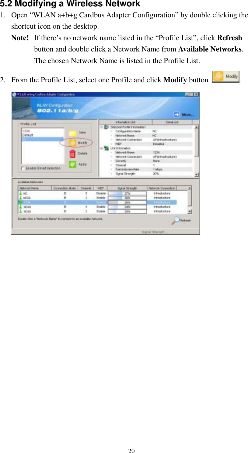
Wistron NeWeb CB9GP WLAN a+b+g Cardbus Adapter User Manual Manual
Wistron NeWeb Corporation WLAN a+b+g Cardbus Adapter Manual
UserManual.wiki
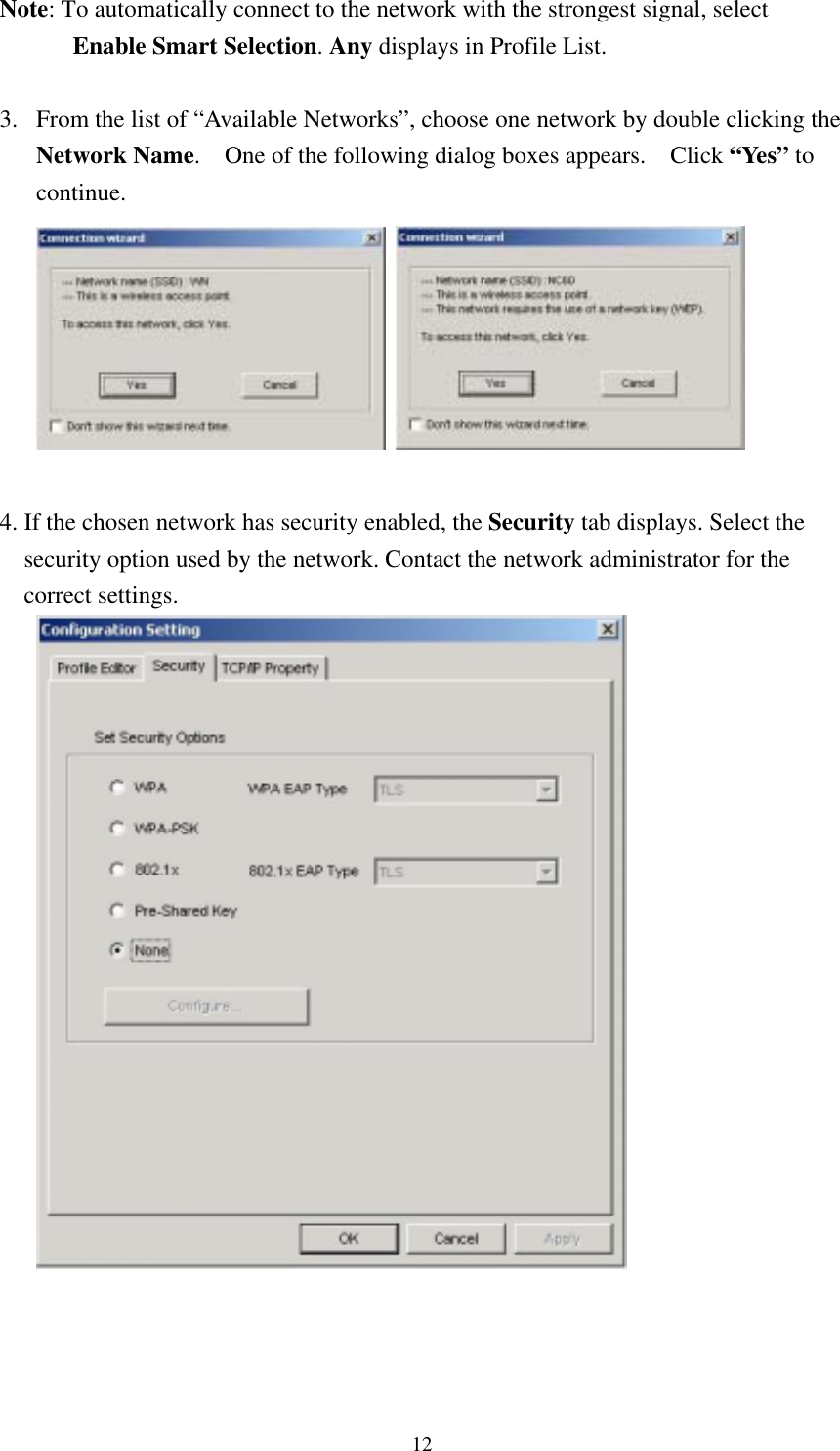
>
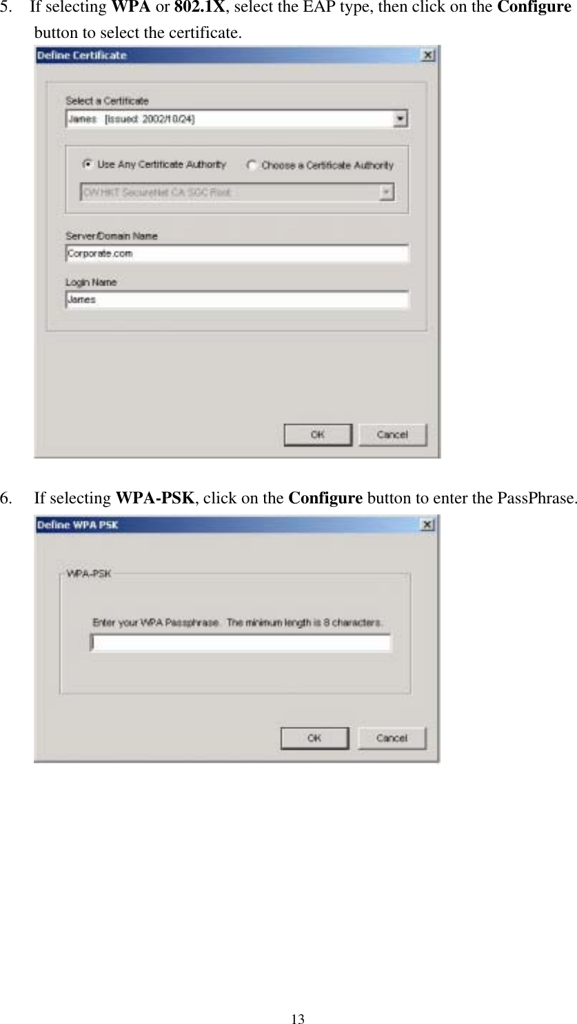
Wistron NeWeb
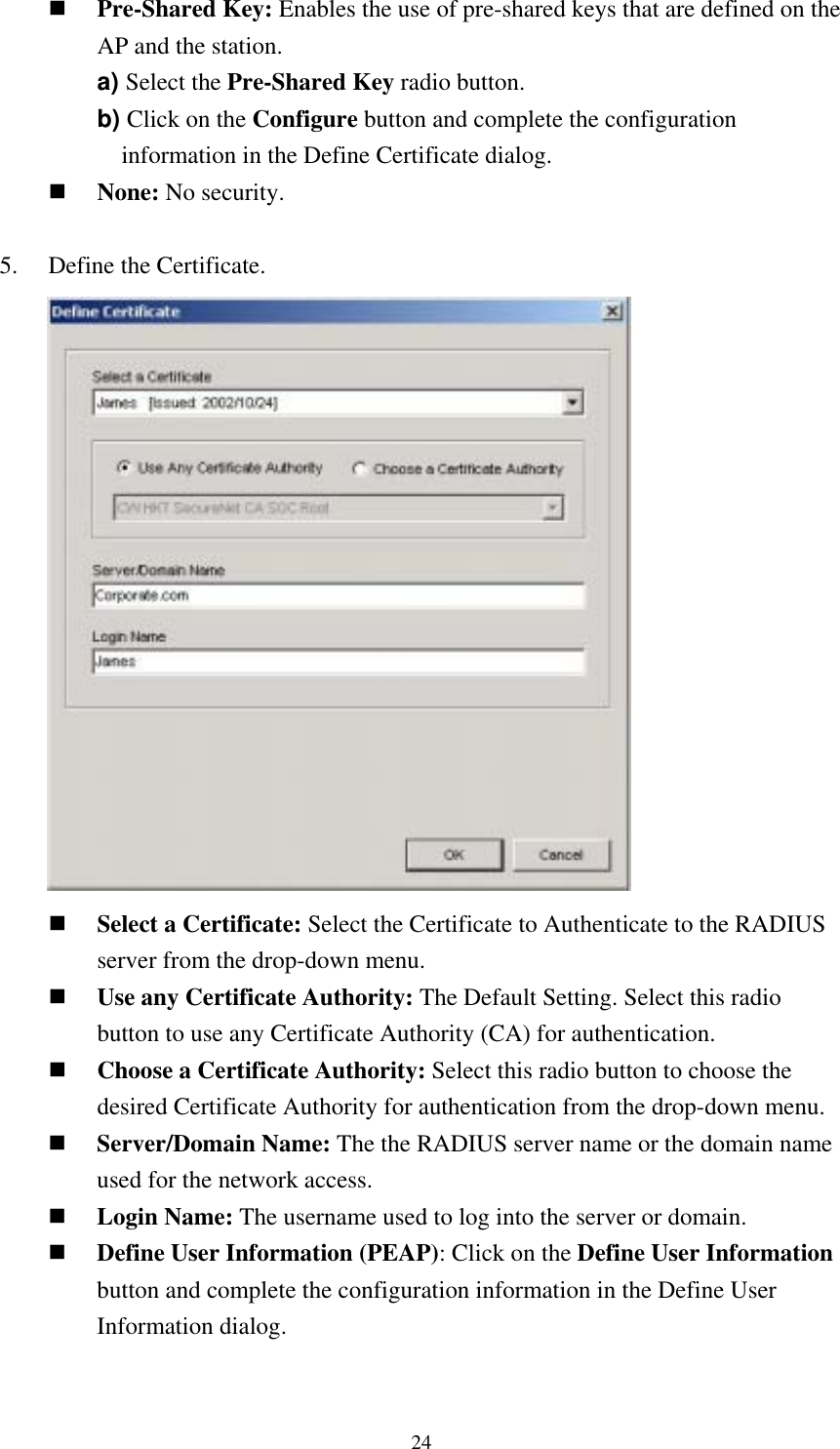
>
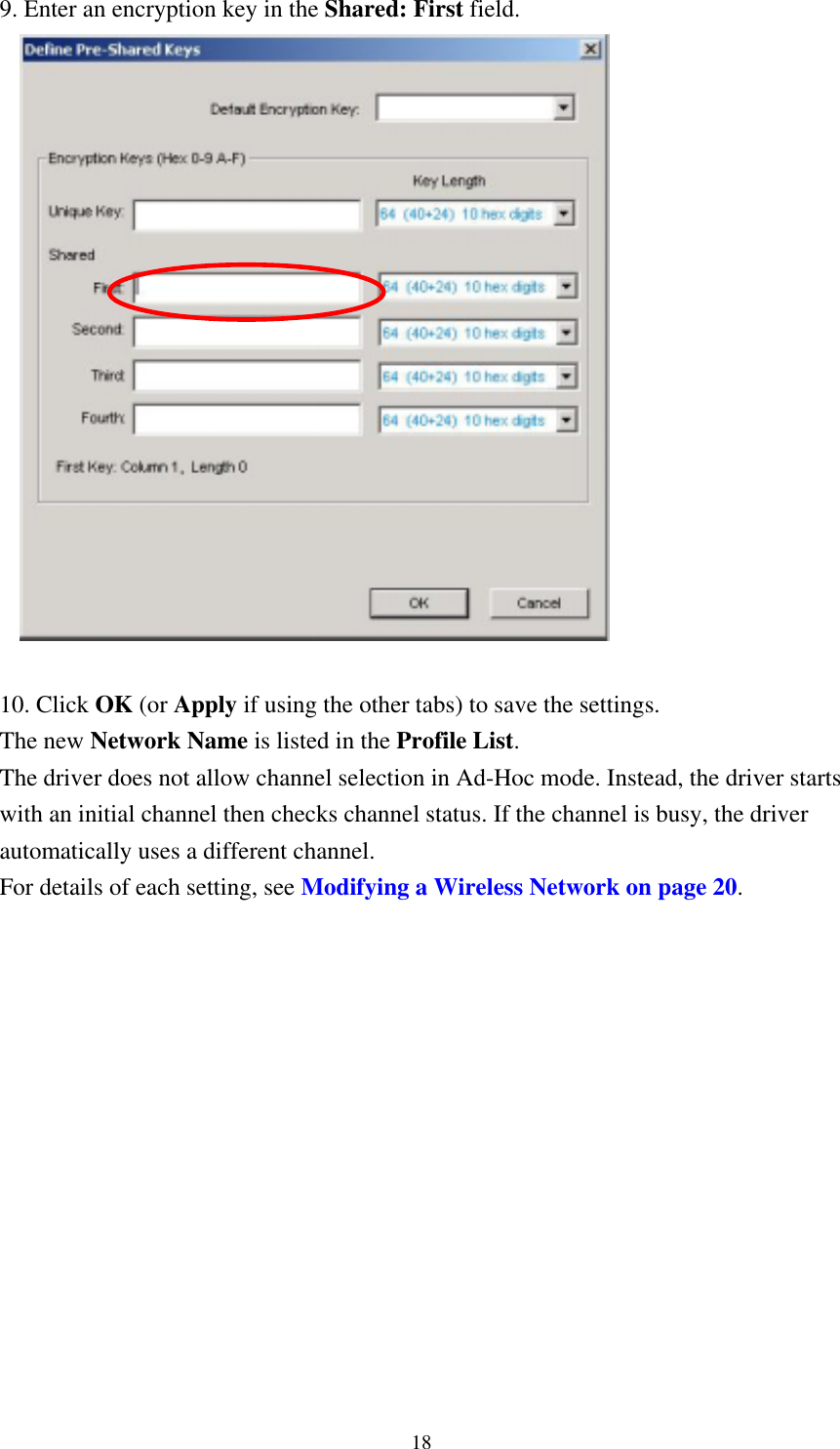
CB9GP User Manual
>
Manual
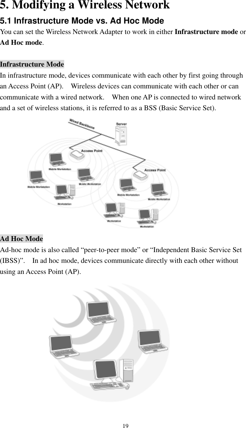
Contents
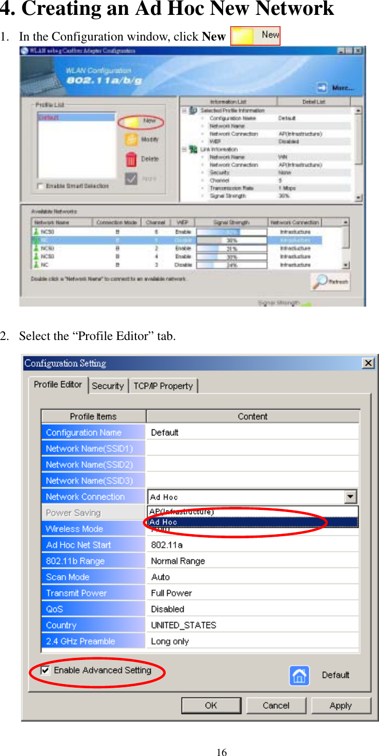
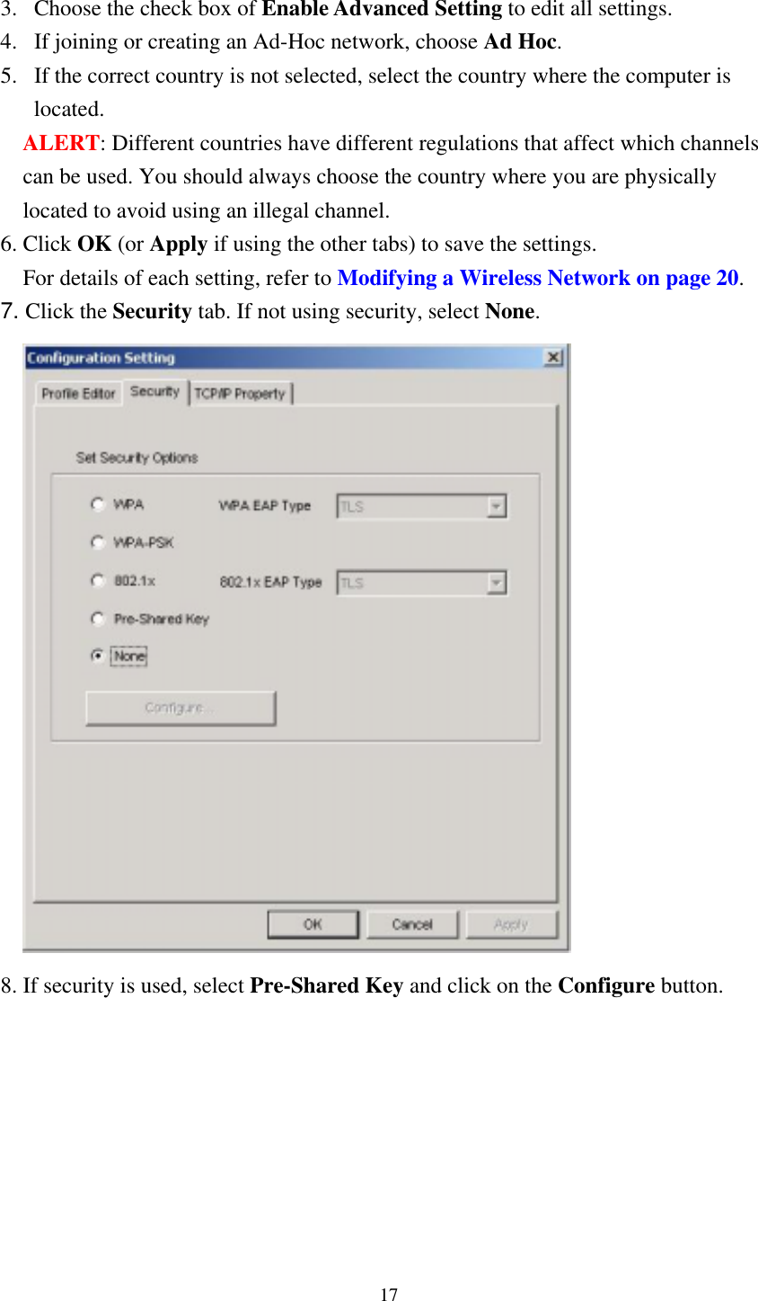
1.
RF Exposure Statement
2.
Manual
3.
Statement for Manual
Manual
Navigation menu
Upload a User Manual
Namespaces
Wiki Guide
HTML
PDF
Info
Views
User Manual
Discussion / Help
Navigation