Wistron NeWeb CRP-1 802.11 a/g Super A/G Intelligent WLAN Router User Manual 802 11 a g Router
Wistron NeWeb Corporation 802.11 a/g Super A/G Intelligent WLAN Router 802 11 a g Router
UserManual.wiki
>
Wistron NeWeb
>
CRP 1 User Manual
Users Manual
Navigation menu
Upload a User Manual
Namespaces
Wiki Guide
HTML
PDF
Info
Views
User Manual
Discussion / Help
Navigation

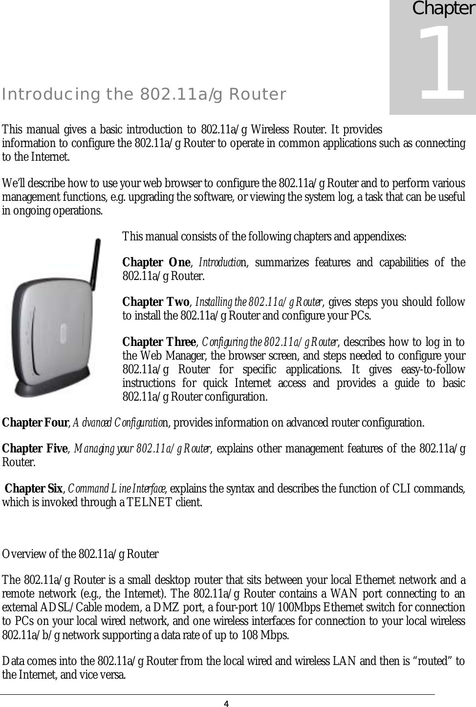
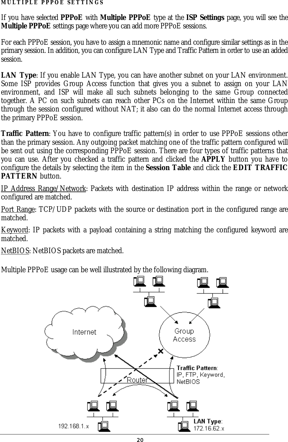

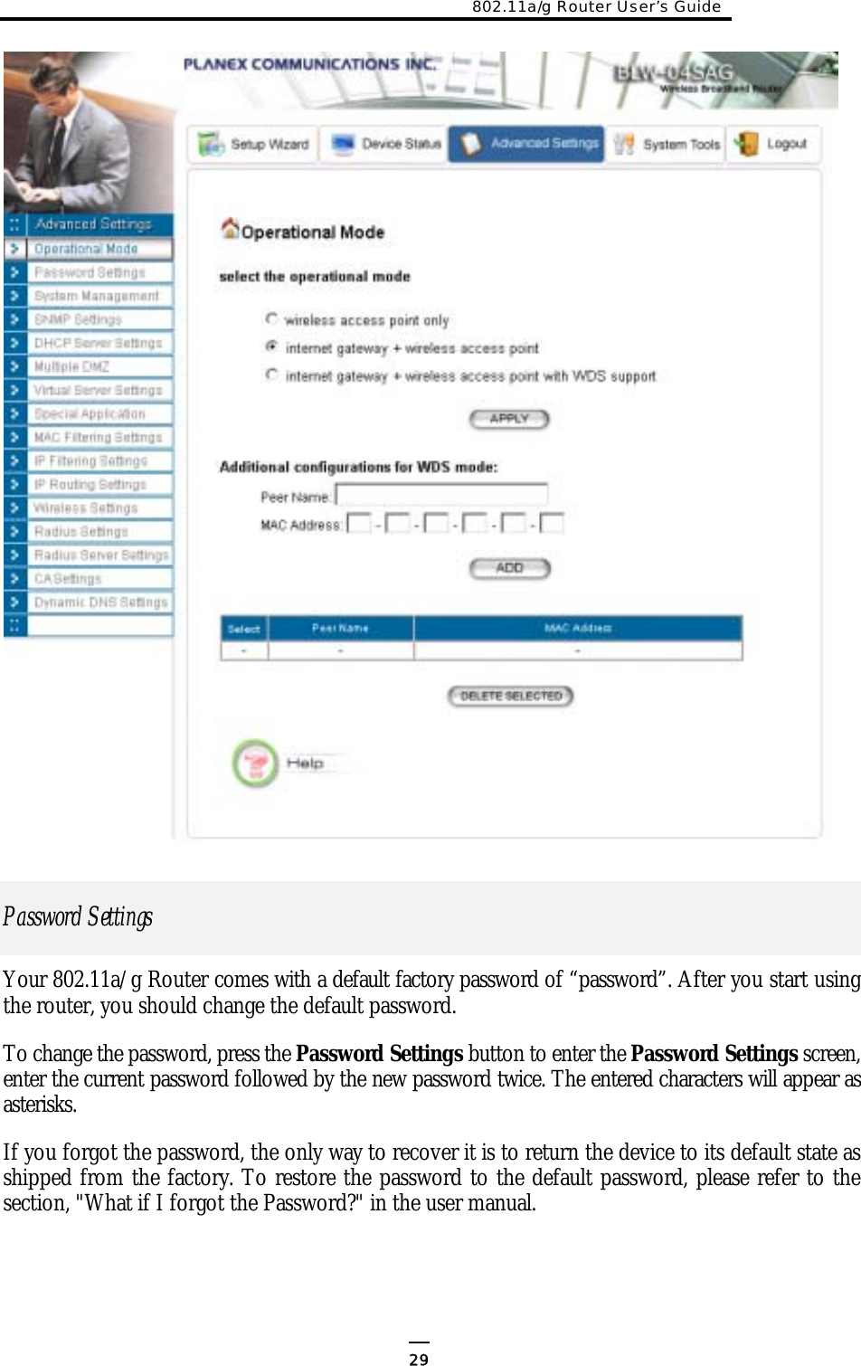
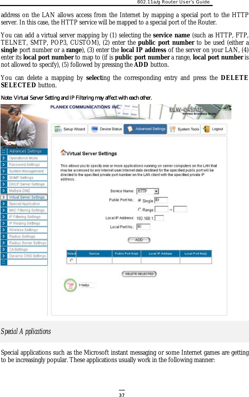
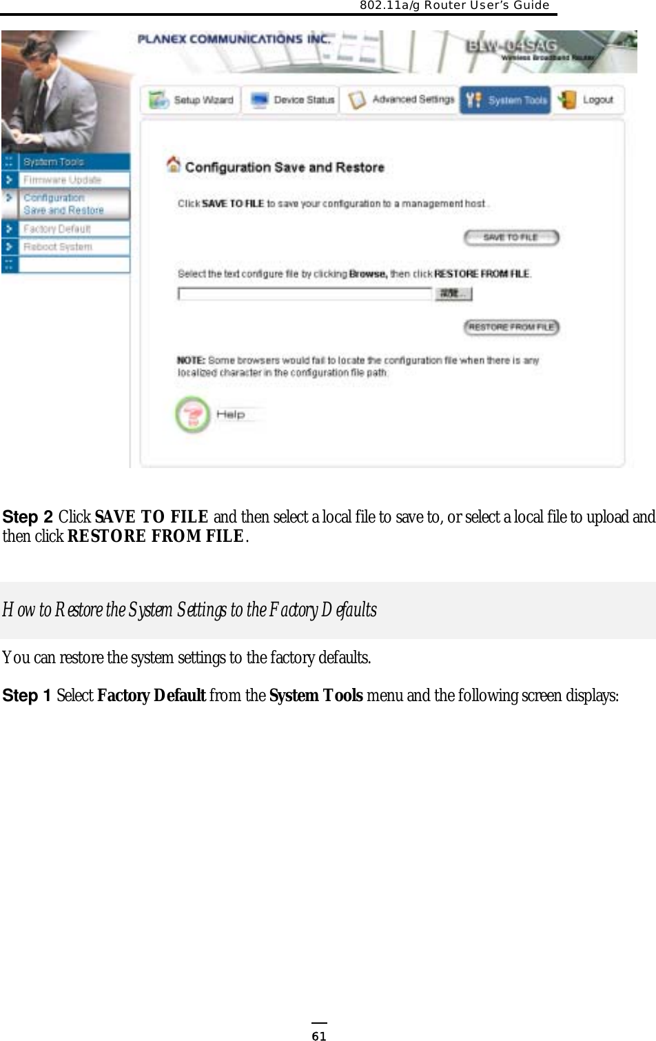
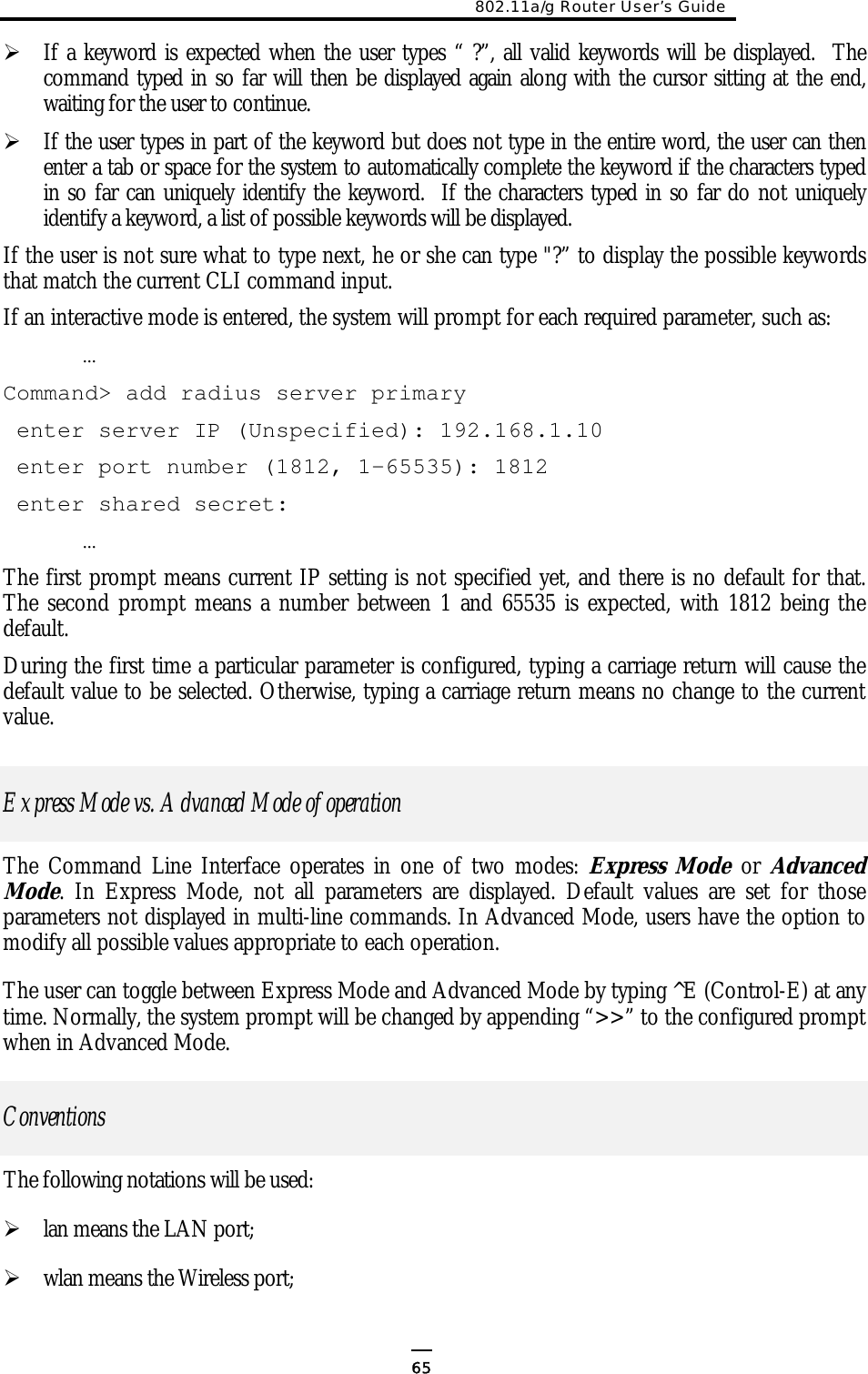
![ <> specifies the arguments of the command, <1-4> means a number between 1 to 4; [ ] indicates an optional parameter | is used to separate alternative choices of parameters or keywords; {} encloses all alternative keywords; MacAddr, or XX-XX-XX-XX-XX-XX means any MAC address in hexadecimal format, where each XX can be 00, 01, ... 99, 0A, 0B, 0C, 0D, 0E, 0F, 10, 11,… FF; ipAddr, netmask, or xxx.xxx.xxx.xxx means any ip address or network mask, where xxx is a decimal integer between 0 and 255; The term string means a string of characters up to the specified length, which may be enclosed in double quotes (“) (required if the string contains embedded blanks); Names representing filters and MAC addresses could be up to 30 characters in length; password and SNMP community read/write strings are up to 15 characters in length. When the password and SNMP community write string are entered, they are echoed back as a string of “*”s for protection, while other parameters, such as WEP keys, are echoed back the way they are typed (in clear text). List of Commands From a functional point of view, CLI commands will be grouped into the following categories: (1) System (2) IP (3) Filtering (4) DHCP Server (5) SNMP (6) Diagnostics (7) Security The command format will be described in the following sections. (1) System Commands clear config Description: Reset the system configuration to the factory default. disable ntp client Description: Disable the NTP (Network Time Protocol) client function. 66](https://usermanual.wiki/Wistron-NeWeb/CRP-1/User-Guide-420000-Page-67.png)
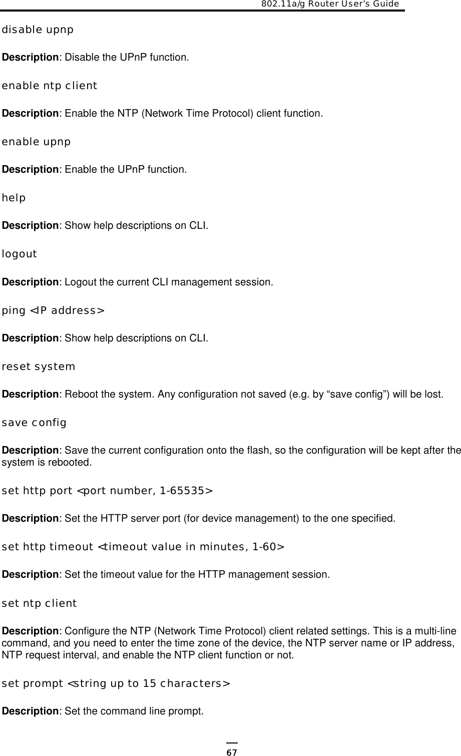
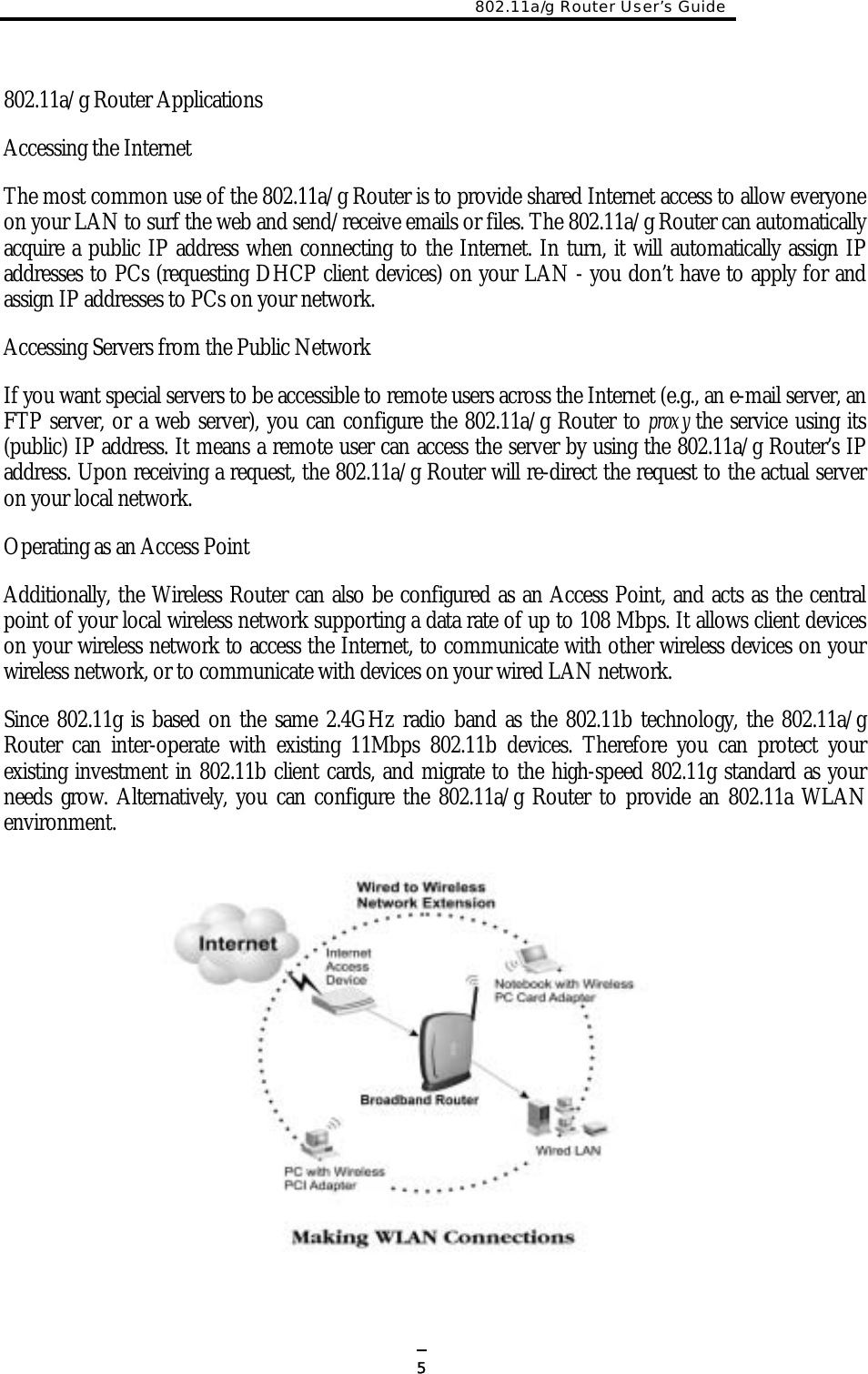
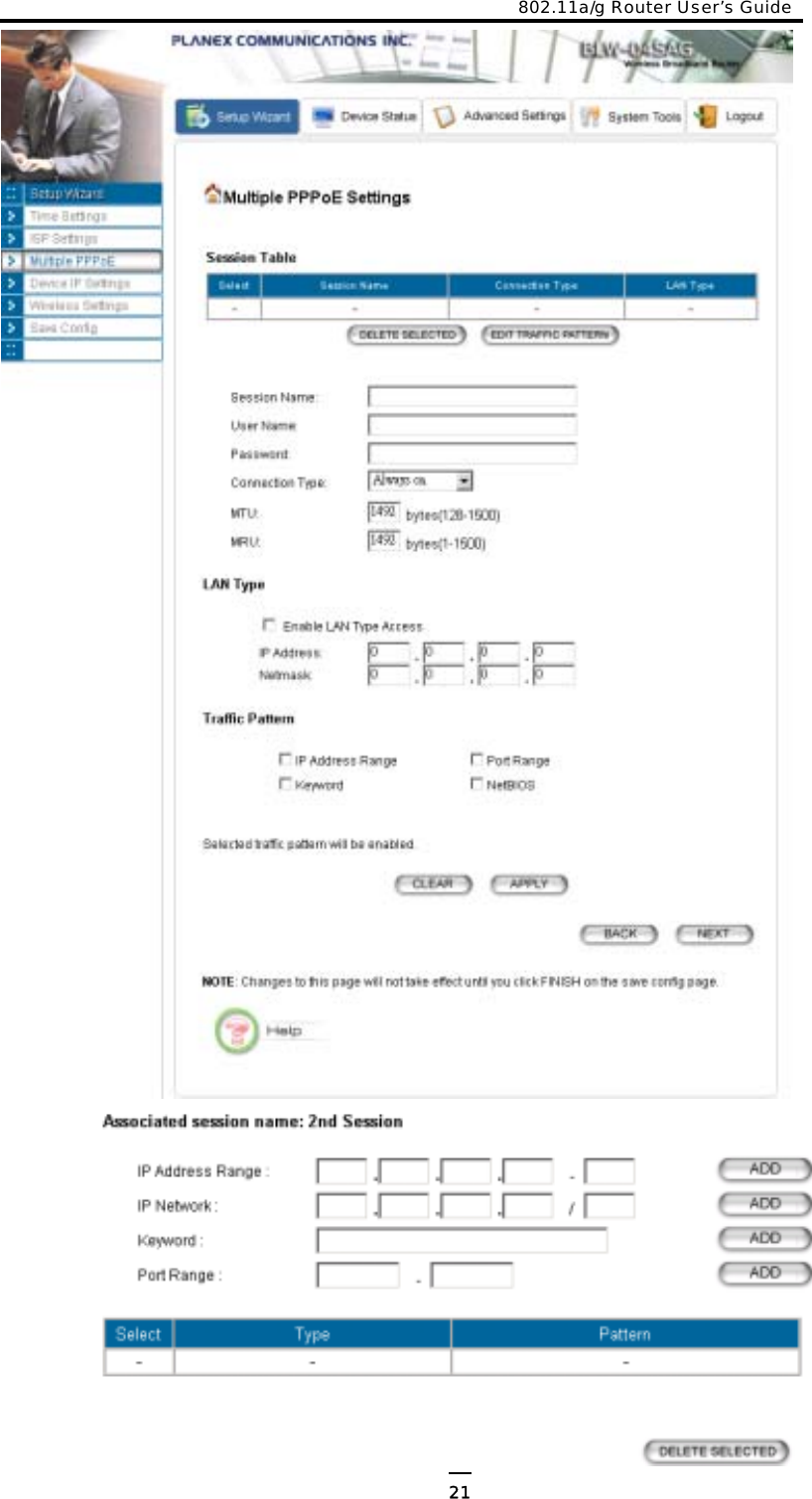
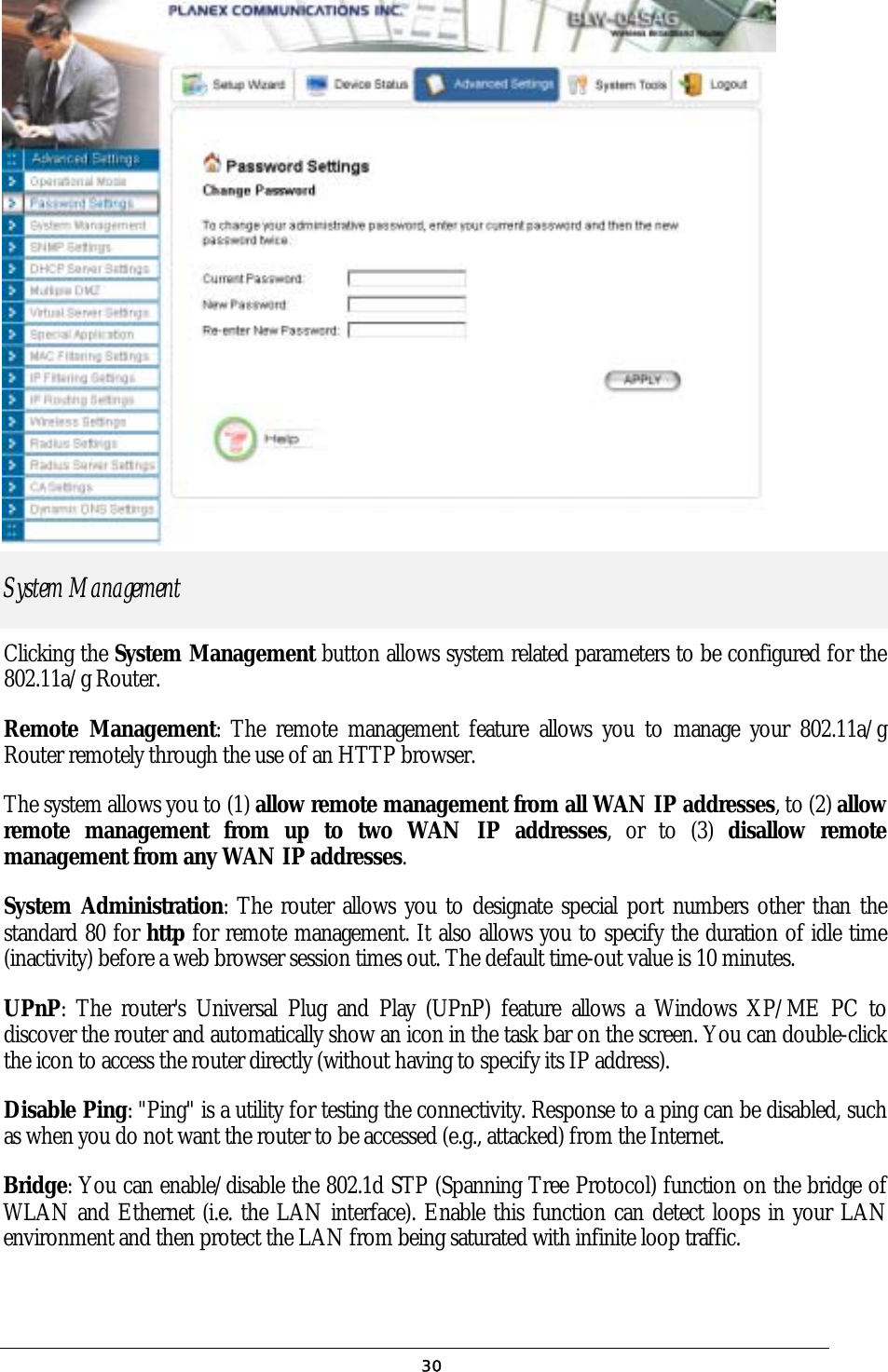
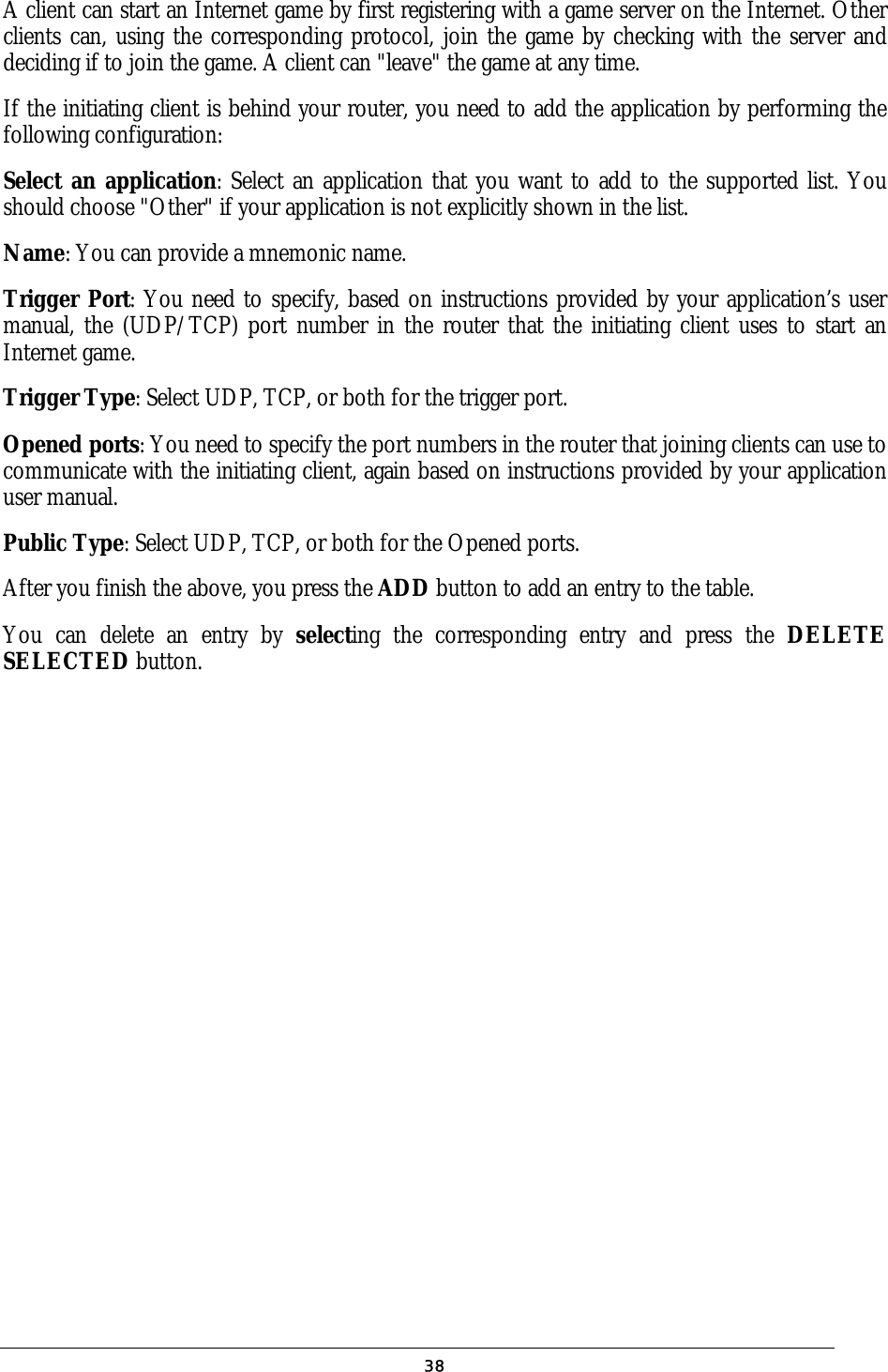
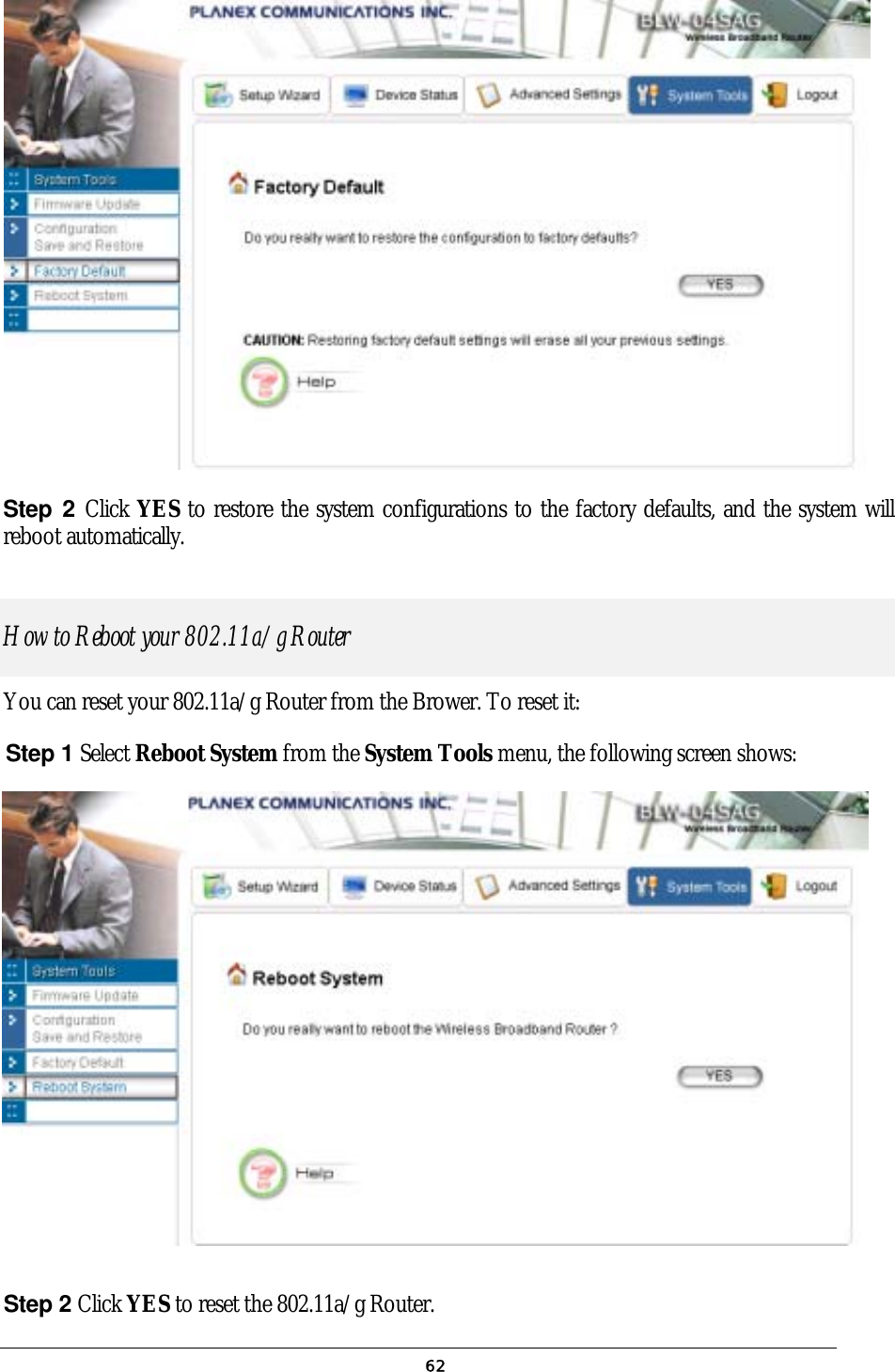
![802.11a/g Router User’s Guide Description: Display the current configurations of the TELNET management function. show upnp Description: Display the current configurations of the UPnP function. (2) IP Commands add ip default route <gateway address> Description: Add an IP default route to go to the specified gateway IP address. add ip route <destination IP> <destination netmask> <gateway address/interface name> <hop counts> Description: add an IP route to the destination network specified through the specified gateway or interface with the specified cost. A <destination netmask> is in the format of xxx.xxx.xxx.xxx, for example, 255.255.254.0. delete ip default route Description: Delete the IP default route. delete ip route <destination IP> <destination netmask> Description: Delete the IP to the specified network. disable rip <interface name, string up to 15 characters> Description: Disable the RIP function on the specified interface. enable {rip1 | rip2} {active | passive} [<interface name, string up to 15 characters>] Description: Enable and set RIP mode as RIP1/RIP2 active/passive on the specified interface. If no interface is specified, this setting applied to all interfaces. show ip routing table Description: Display the system IP routing table. show rip [<interface name, string up to 15 characters>] Description: Display the current RIP settings on the specified interface. If no interface is specified, this command displays the current RIP settings on all the interfaces. (3) Filtering Commands add mac filter <string up to 30 characters> <MAC address, XX-XX-XX-XX-XX-XX> Description: Add a MAC filter with the specified name (a mnemonic name) and MAC address. delete mac filter <string up to 30 characters> 69](https://usermanual.wiki/Wistron-NeWeb/CRP-1/User-Guide-420000-Page-70.png)
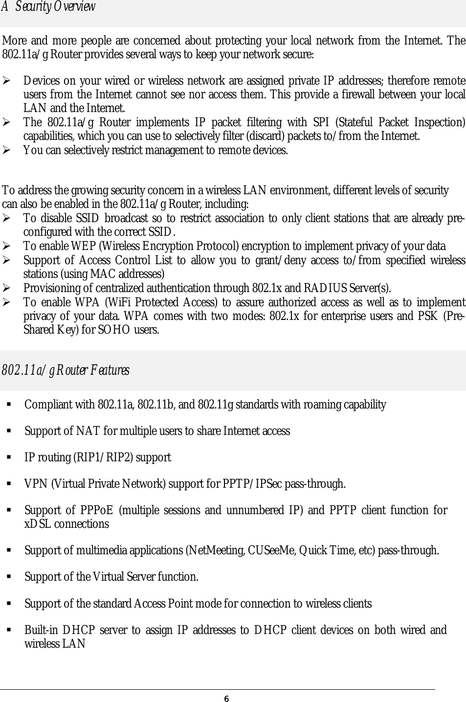
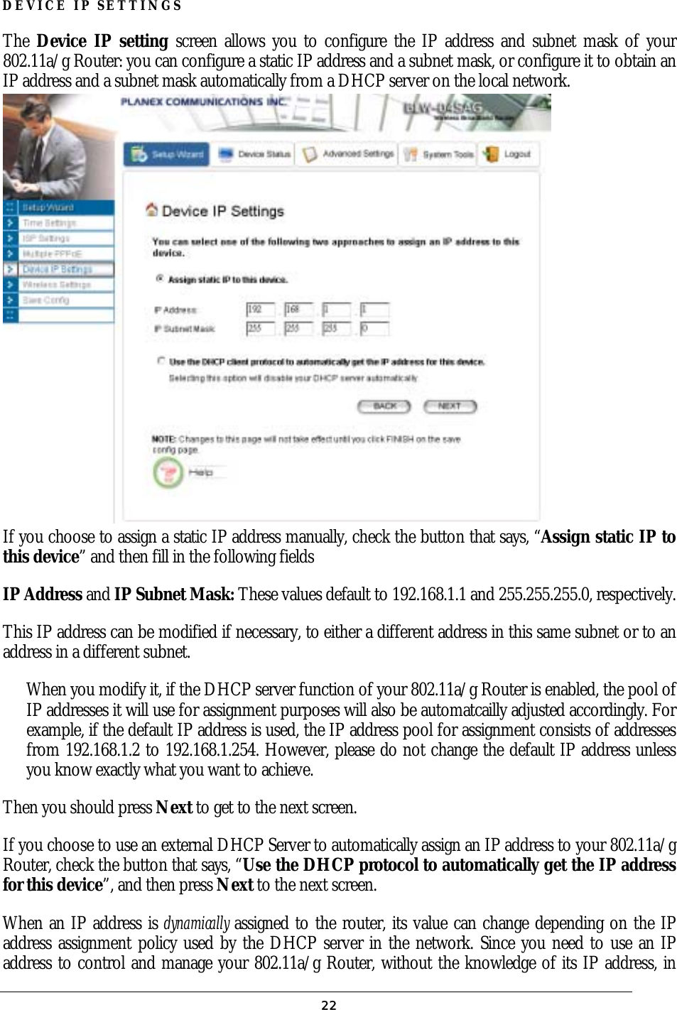
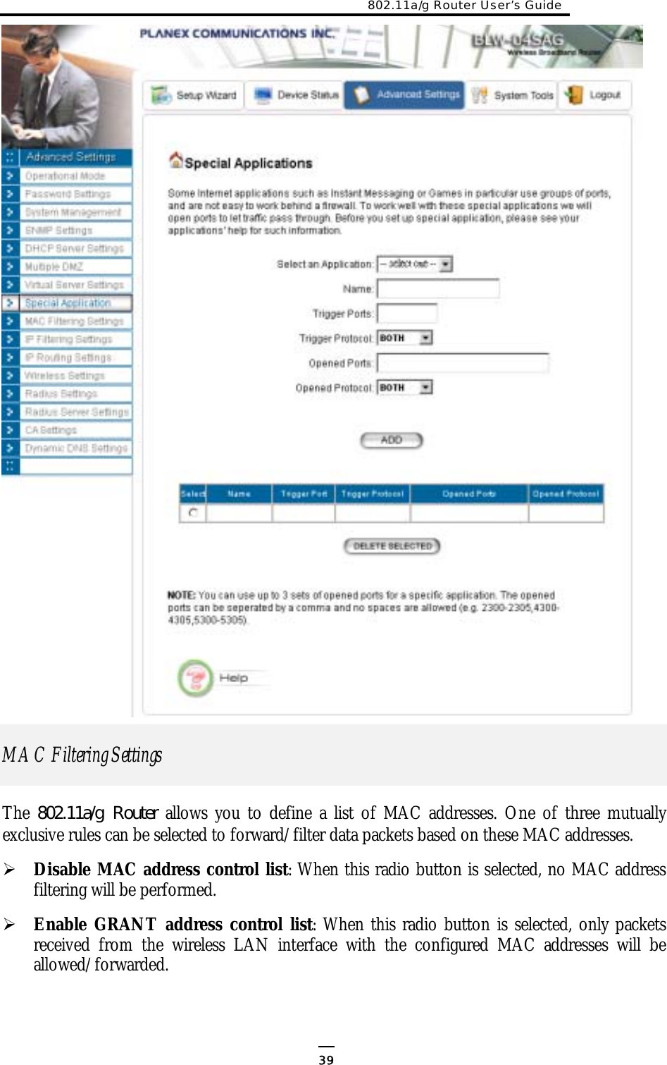
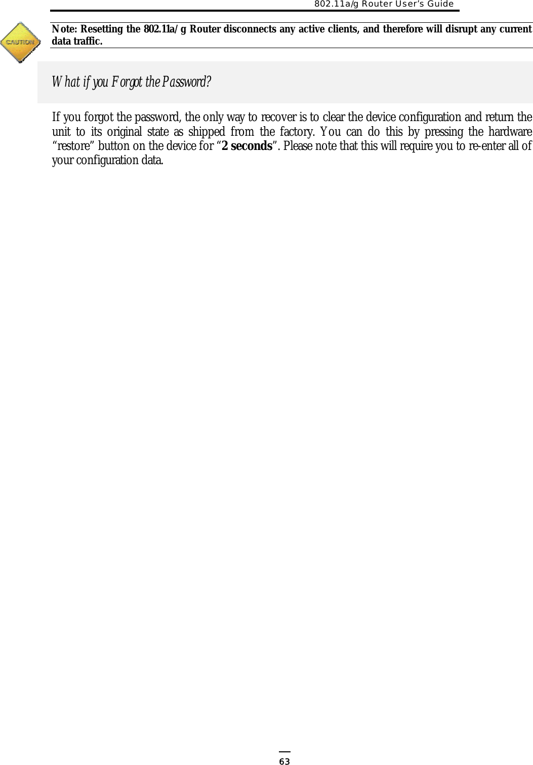
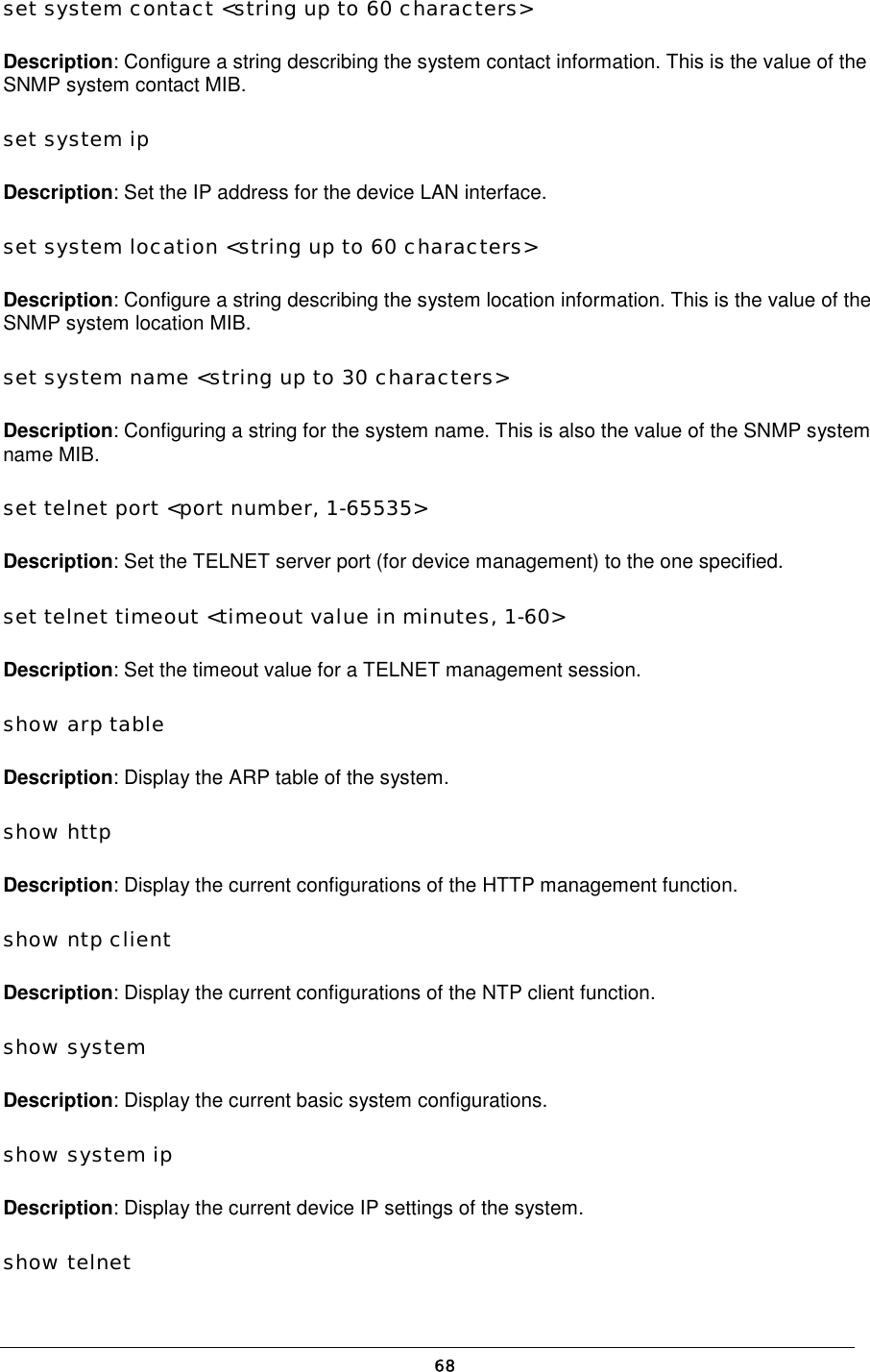
![Description: Delete the MAC filter with the specified name. set mac filter mode <MAC filter mode, disabled/grant/deny> Description: Set the MAC filter mode. show mac filter [<string up to 30 characters>] Description: Display the MAC filter entry with the specified name. If no name is specified, this command display all currently configured MAC filter entries. show mac filter mode Description: Display the currently configured MAC filter mode. (4) DHCP Server Commands add dhcp static <IP address> <MAC address, XX-XX-XX-XX-XX-XX> Description: Add a static DHCP client entry with the specified IP address and MAC address. delete dhcp static <IP address> Description: Delete the static DHCP client entry with the specified IP address. disable dhcp server Description: Disable the DHCP server function. enable dhcp server Description: Enable the DHCP server function. set dhcp server Description: Configure the DHCP server related settings. This is a multi-line command, and you have to enter the IP address pool range, gateway IP address, and lease period. show dhcp client table Description: Display the current dynamic DHCP clients. show dhcp server Description: Display the current DHCP server settings. show dhcp static Description: Display the current static DHCP clients. 70](https://usermanual.wiki/Wistron-NeWeb/CRP-1/User-Guide-420000-Page-71.png)
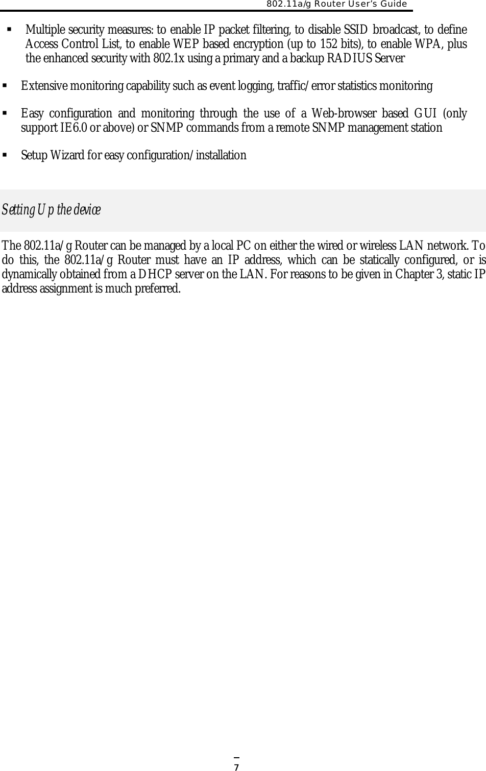
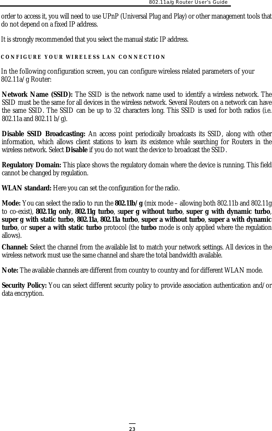
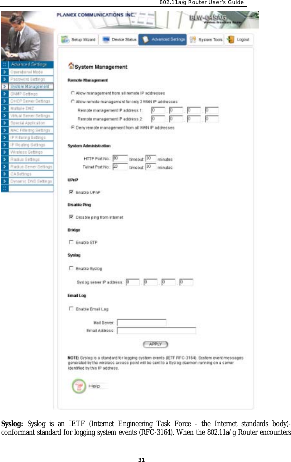
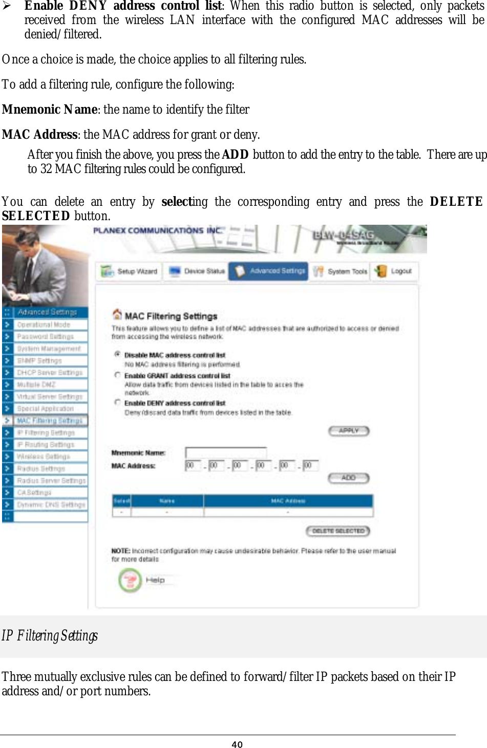
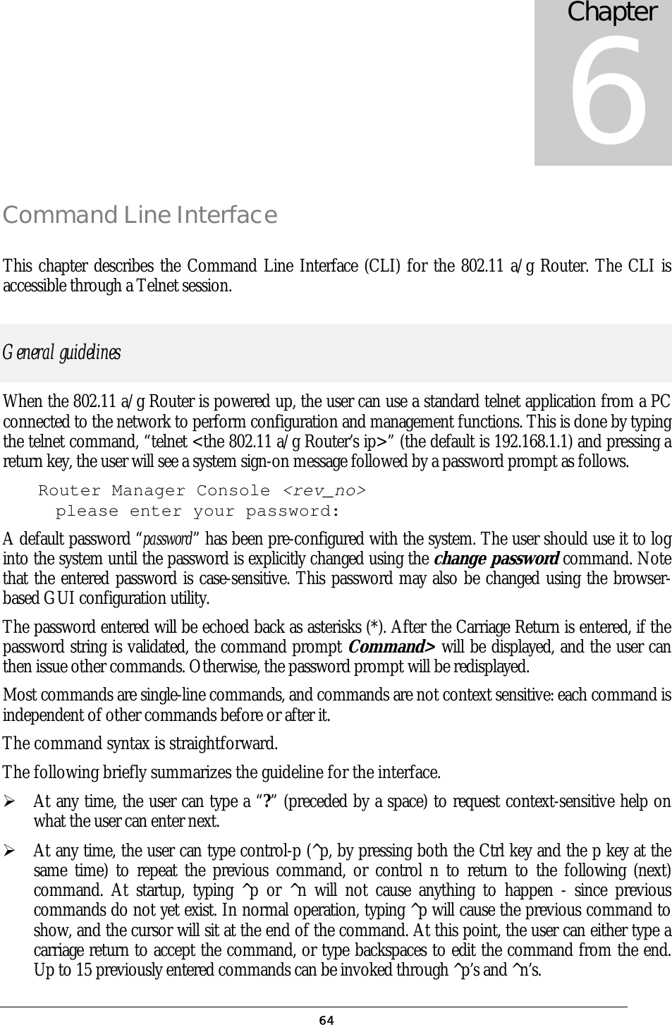
![802.11a/g Router User’s Guide (5) SNMP Commands disable snmp Description: Disable the SNMP function. enable snmp Description: Enable the SNMP function. set community string {read | write} <string up to 15 characters> Description: Configure the SNMP READ/WRITE community string. show community string read Description: Display the SNMP READ community string. show snmp Description: Display the current SNMP settings. show snmp statistics Description: Display the current SNMP statistics. show trap manager [<string up to 30 characters>] Description: Display the settings of the specified SNMP trap manager. If no trap manager is specified, this command displays the settings of all trap managers. (6) Diagnostics Commands disable log <facility> Description: Disable the log function on the specified facility. disable syslogd Description: Disable the remote log function. disable trace <facility> Description: Disable the trace function on the specified facility. enable log <facility> [<log level, 1-7>] Description: Enable the log function with the specified log level on the specified facility. If no log level is specified, the previously configured log level is used. enable syslogd 71](https://usermanual.wiki/Wistron-NeWeb/CRP-1/User-Guide-420000-Page-72.png)
![Description: Enable the remote log function. enable trace <facility> [<log level, 1-7>] Description: Enable the trace function with the specified log level on the specified facility. If no log level is specified, the previously configured log level is used. set log level <log level, 1-7> Description: Set the log level. set syslogd <IP address> Description: Configure the IP address of the remote syslog daemon. This is used for the remote syslog function. show log level Description: Display the current log level. show log table [<facility>] Description: Display the current logged events of the specified facility. If no facility is specified, this command displays all logged events. show syslogd Description: Display the current configuration of the remote log function. (7) Security Commands add radius server {primary | secondary} Description: Configure the primary/secondary RADIUS server settings. This is a multi-line command, and you have to enter the IP address and port number of the server, shared secret, and enable/disable. change password Description: Change the password for management, including HTTP and TELNET. disable radius mac authentication Description: Disable the use of external RADIUS servers for MAC address access control. disable radius server {primary | secondary} Description: Disable the use of the primary/secondary RADIUS server. enable radius mac authentication Description: Enable the use of external RADIUS servers for MAC address access control. 72](https://usermanual.wiki/Wistron-NeWeb/CRP-1/User-Guide-420000-Page-73.png)
![802.11a/g Router User’s Guide enable radius server {primary | secondary} Description: Enable the use of the primary/secondary RADIUS server. set radius server reattempt <reattempt interval in minutes, 5-60> Description: Configure the reattempt time for the system to contact the primary RADIUS server after the primary RADIUS server was down. set radius server retry <retry interval in times, 1-5> Description: Configure the number of retries after which the system may think the RADIUS server is down. show radius server [{primary | secondary}] Description: Display the configuration of the specified RADIUS server. If no server is specified, this command displays the configurations of all RADIUS servers. 73](https://usermanual.wiki/Wistron-NeWeb/CRP-1/User-Guide-420000-Page-74.png)
![Text Configuration The text configuration provides another way for users to configure the 802.11 a/g Router. Users can save the system current configuration onto a file on PC, edit the configuration file, and then restore the system configuration with the configuration file. For details regarding the save and restore configuration operations, please read the HOW TO SAVE OR RESTORE CONFIGURATION CHANGES section in the MANAGING YOUR 802.11A/G ROUTER chapter. This chapter describes the syntax and semantics of a text configuration file. General guidelines The format of a text configuration file is like the Microsoft Window® INI (extension file name: .ini) file format. The basic file structure can be divided into the following parts: 1. Sections A section name is enclosed in square brackets, alone on a line. Section names are allowed to contain any character but square brackets or linefeeds. For example: “[sectionName]”. Basically a section corresponds to a configuration item, a section contains zero or more key and value pairs that are the settings for the configuration item. A section name is case insensitive. 2. Keys and Values A section contains zero or more key and value pairs, declared with the syntax “key = value”. A key is a string without space and the value consists of all characters at the right hand side of the equal sign. That is, a key starts with the first non-blank ASCII character at the right hand side of an equal sign and extends to a comment mark (if there is one) or the end of the line. So blanks are allowed among non-blank characters. A key string is case insensitive. 3. Comments A comment starts with a semicolon or a hash sign and extends to the end of the line. List of Sections Section & Examples Description [Manufacture] This is used by the system itself, and this should be Chapter 6 74](https://usermanual.wiki/Wistron-NeWeb/CRP-1/User-Guide-420000-Page-75.png)
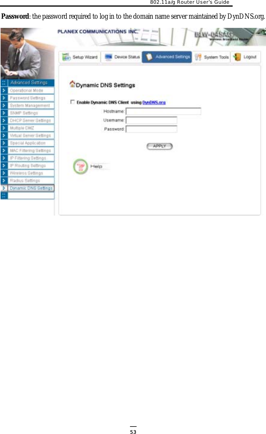
![802.11a/g Router User’s Guide Version = 1.00 put as the first section in a configuration file. Users should not modify anything in this section. [Password] Password=000000 Password: the password for system management. [Time] TimeZone = +09:00 NTPstate=disable NTPstate=enable NTPServerType =ip NTPServerIP=192.43.244.18 NTPServerType =name NTPServerName=time.nist.gov RequestInterval=24 TimeZone: the time zone of the system. Possible values are -12:00, -11:00, -10:00, …, +00:00, +01:00, …, +13:00. NTPstate: enable NTP client function or not (‘enable’or ‘disable’). If ‘NTPstate’ is ‘enable’: NTPServerType: how to specify the NTP server (‘ip’ or ‘name’). NTPServerIP: the IP address of the NTP server (if ‘NTPServerType’ is ‘ip’). NTPServerName: the domain name of the NTP server (if ‘NTPServerType’ is ‘name’). RequestInterval: the interval that the NTP client will query the server periodically (unit: hours). [Device] IPType=static IPAddress=192.168.1.1 IPNetmask=255.255.255.0 IPType=dhcp LAN Interface Configuration IPType: the LAN IP type (‘static’ or ‘dhcp’) For ‘static’ type: IPAddress: the IP address of LAN IPNetmask: subnet mask of LAN [ISP] ISPType=static ISPStaticIP=100.0.0.1 ISPNetmask=255.255.0.0 ISPGateway=100.0.0.2 ISPDNSIP=123.0.0.1 ISPType=dhcp Hostname=name ISPType=pppoe PPPoEUserName=name PPPOEPassword=password PPPOEServiceName=service PPPOEConnectionType=demand_dialing PPPOEMTU=1492 PPPOEMRU=1492 PPPOESessionType=normal WAN Interface Configuration ISPType: the WAN connection type (‘static’, ‘dhcp’, ‘pppoe’, ‘pptp’). For ‘static’ type: ISPStaticIP: the IP address assigned by ISP. ISPNetmask: the netmask assigned by ISP. ISPGateway: the default gateway address assigned by ISP. ISPDNSIP: the DNS server address assigned by ISP. For ‘dhcp’ type: Hostname: the host name (if any) assigned by your ISP. For ‘pppoe’ type: PPPoEUserName: user name of the ISP account PPPOEPassword: password for the ISP account 75](https://usermanual.wiki/Wistron-NeWeb/CRP-1/User-Guide-420000-Page-76.png)
![PPPOESessionType=unnumbered_link KeepPrivateLan=enable/disable UnnumberedIP=192.168.1.1 UnnumberedNetmask=255.255.255.0 ISPType=pptp PPTPLocalIP=11.0.0.10 PPTPNetmask=255.255.255.0 PPTPRemoteIP=11.0.0.1 PPTPUserName=name PPTPPassword=password PPTPIdleTimeout=time PPPOEServiceName: service name for the connection PPPOEConnectionType: type of the PPP connection (‘demand_dialing’, ‘always_on’, ‘manually’). PPPOEMTU/PPPOEMRU: the MTU/MRU for the connection (unit: byte). PPPOESessionType: type of the PPPoE session (‘normal’, ‘multiple_pppoe’, ‘unnumbered_link’). For PPPoE ‘unnumbered_link’ session type: KeepPrivateLan: keep the private LAN or not (‘enable’ or ‘disable’). UnnumberedIP: the IP address of the private LAN if ‘KeepPrivateLan’ is ‘enable’ UnnumberedNetmask: the subnet mask of the private LAN if ‘KeepPrivateLan’ is ‘enable’ For ‘pptp’ type: PPTPLocalIP: the local IP address for establishing the PPTP tunnel. PPTPNetmask: the subnet mask of the WAN interface where the PPTP tunnel is established. PPTPRemoteIP: the remote IP address for establishing the PPTP tunnel. PPTPUserName: the user name of the ISP account. PPTPPassword: the password name of the ISP account. PPTPIdleTimeout: the maximum idle time before the connection is taken down (unit: minute). [MultiplePPPoEEntry] MpppoeSessionName=session name MpppoeUserName=name MpppoePassword=password MpppoeConnectionType=manually MpppoeMTU=1492 MpppoeMRU=1492 MpppoeLanType=enable MpppoeLanIP=2.2.0.0 MpppoeLanNetmask=255.255.0.0 TPIPRange=enable TPPortRange=disable TPKeyword=disable TPNetBios=enable TPRuleIPRange=50.0.0.0-20 Multiple PPPoE Sessions Configuration There could be multiple entries (max 7 entries), each entry contains the following items: MpppoeSessionName: a mnemonic name for this entry. MpppoeUserName: the user name for the ISP account. MpppoePassword: the password for the ISP account.MpppoeConnectionType: type of the PPP connection (‘demand_dialing’, ‘always_on’, ‘manually’). MpppoeMTU/MpppoeMRU: the MTU/MRU for the connection (unit: byte). MpppoeLanType: Enable the LAN type access on the session or not (‘enable’ or ‘disable’) MpppoeLanIP: the IP address of the LAN type network if ‘MpppoeLanType’ is ‘enable’. MpppoeLanNetmask: the subnet mask of the LAN 76](https://usermanual.wiki/Wistron-NeWeb/CRP-1/User-Guide-420000-Page-77.png)
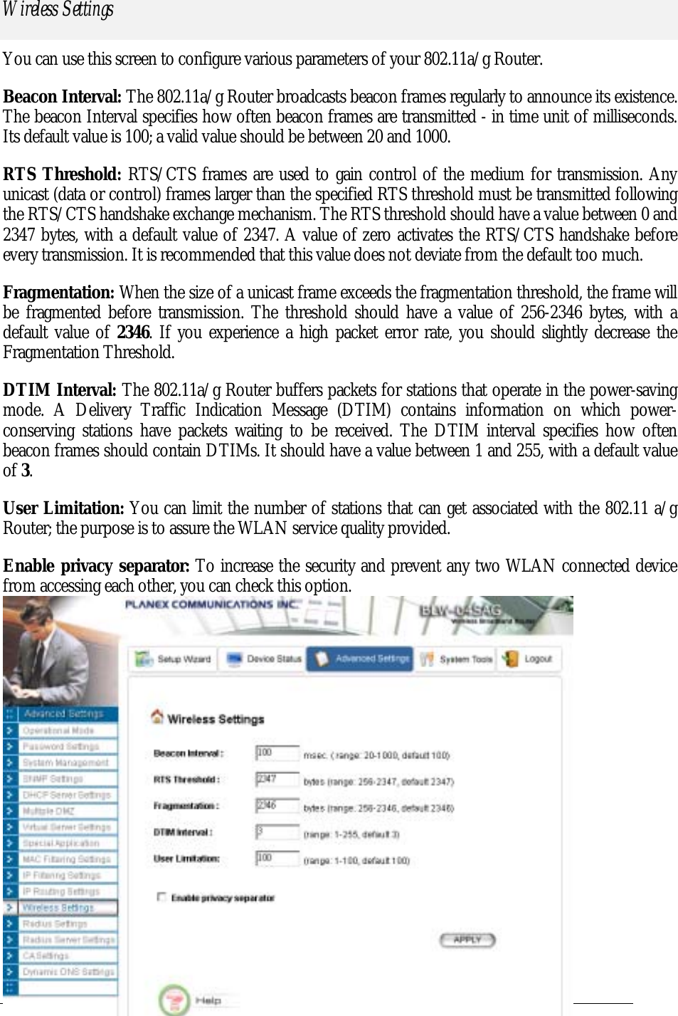
![802.11a/g Router User’s Guide TPRuleNetwork=60.0.0.0/24 TPRulePortRange=40000-50000 TPRuleKeyword=key pattern type network if ‘MpppoeLanType’ is ‘enable’. TPIPRange: whether enable IP address range and network traffic pattern on the session (‘enable’, ‘disable’). TPPortRange: whether enable port range traffic pattern on the session (‘enable’, ‘disable’). TPKeyword: whether enable keyword traffic pattern on the session (‘enable’, ‘disable’). TPNetBios: whether enable NetBIOS traffic pattern on the session (‘enable’, ‘disable’). The following items can appear more than one in a multiple PPPoE entry: TPRuleIPRange: specify an IP address range traffic pattern. TPRuleNetwork: specify an IP network traffic pattern. TPRulePortRange: specify a port range traffic pattern. TPRuleKeyword: specify a keyword traffic pattern. [CloneMAC] CloneMACState=disable CloneMAC=00-01-02-03-04-05 Clone MAC Configuration CloneMACState: whether enable the clone MAC function (‘disable’, ‘enable’). CloneMAC: the MAC address to be cloned. [Radio] SSID=wlan SSIDBoradcast=enable RadioMode=11g/b Channel=auto PrivSeparatorState=disable BeaconInterval=100 RTSThreshold=2347 Fragmentation=2346 DTIMInterval=3 UserLimit=100 WLAN Configuration SSID: SSID of the WLAN. SSIDBoradcast: whether enable SSID broadcast. RadioMode: radio mode (‘11a’, ‘11at’-a turbo, ‘11sa’-super a without turbo, ‘11sast’-super a with static turbo, ‘11sadt’-super a with dynamic turbo, ‘11g/b’-11g or 11b, ‘11g’, ‘11gt’-g turbo, ‘11sg’-super g without turbo, ‘11sgst’-super g with static turbo, ‘11sgdt’-super g with dynamic turbo). Channel: channel number (1, 2, 3… or ‘auto’). PrivSeparatorState: whether enable privacy separator (‘enable’, ‘disable’). BeaconInterval: beacon interval (unit: msec). RTSThreshold: RTS threshold (unit: byte). Fragmentation: fragmentation threshold (unit: byte). DTIMInterval: DTIM interval. UserLimit: user limitation count. [SecurityPolicy] SecurityPolicy=none WLAN Security Policy SecurityPolicy: security policy (‘none’, ‘wep’) 77](https://usermanual.wiki/Wistron-NeWeb/CRP-1/User-Guide-420000-Page-78.png)
![SecurityPolicy=wep WEPAutoGenerateKey=enable WEPPassPhrase=pass phrase WEPPassPhraseLength=64 WEPAutoGenerateKey=disable WEPKey1Type=ascii-64 WEPKey1=12345 WEPKey2Type=hex-128 WEPKey2=f1-05-a1-50-21-f0-d1-b8-83-4e-43-ef-d1 WEPKey3Type=hex-152 WEPKey3=f1-05-a1-50-21-f0-d1-b8-83-4e-43-ef-d1-14-15-16 WEPKey4Type=ascii-152 WEPKey4=this is key- 152 WEPSelectKey=1 SecurityPolicy=802.1x 8021xRekeyLen=128 8021xRekeyInterval=300 SecurityPolicy=wpa-psk WPAPSKKey=12345678 WPAEncryptionType=tkip WPAGroupRekeyInterval=60 SecurityPolicy=wpa WPAEncryptionType=ccmp WPAGroupRekeyInterval=60 For ‘wep’ type, WEPAutoGenerateKey: whether use a pass phrase to generate WEP keys (‘enable’, ‘disable’). WEPPassPhrase: WEP key pass phrase if ‘WEPAutoGenerateKey’ is ‘enable’. WEPPassPhraseLength: the length of keys that should be generated from the pass phrase if ‘WEPAutoGenerateKey’ is ‘enable’. If ‘WEPAutoGenerateKey’ is ‘disable’, the 4 WEP keys should be specified. For each WEP key i, WEPKeyiType specifies the key type, including length and format, and WEPKeyi specifies the key value. The key length can be 64, 128, or 158. The format can be ASCII or HEX. So the available key type is ‘ascii-64’, ‘ascii-128’, ‘ascii-152’, ‘hex-64’, ‘hex-128’, and ‘hex-152’. For an ASCII format key, the key value is the string at the right hand side of the equal sign. For a HEX format key, the format is like xx-xx-…-xx, where each xx is one byte and represented in 2 hexadecimal digits. WEPSelectKey: select which key to use (1, 2, 3, 4). For ‘802.1x’ type, 8021xRekeyLen: the key length for dynamic re-keying, disable means no re-key (‘disable’, 64, 128, 152). 8021xRekeyInterval: re-key interval if ‘8021xRekeyLen’ is not ‘disable’, 0 means only setting key once (unit: sec). For ‘wpa-psk’ type, WPAPSKKey: the pre-shared key (8 ~63 characters) For both ‘wpa-psk’ and ‘wpa’ types WPAEncryptionTypp: encryption protocol types (‘tkip’, ‘ccmp’, ‘both’). WPAGroupRekeyInterval: group key re-key interval (unit: sec). [OperationMode] OpMode=gateway Operational Mode Configuration OpMode: the operational mode setting (‘ap’ – WLAN access point only, ‘gateway’ – internet gateway + WLAN access point, ‘wds’ – internet gateway + wireless access point with WDS support). [WDSEntry] WDS Entry Configuration 78](https://usermanual.wiki/Wistron-NeWeb/CRP-1/User-Guide-420000-Page-79.png)
![802.11a/g Router User’s Guide WDSName=wds peer WDSMAC=00-11-22-33-44-55 There could be multiple entries (max 8 entries), each entry contains the following items: WDSName: a mnemonic name for the peer. WDSMAC: the MAC address of the peer. [SystemManagement] HTTPPort=80 HTTPTimeout=10 TELNETPort=23 TELNETTimeout=10 System Management Configuration HTTPPort: HTTP server port number. HTTPTimeout: idle time out value for a HTTP management session (unit: minute). TELNETPort: TELNET server port number. TELNETTimeout: idle time out value for a TELNET management session (unit: minute). [RemoteManagement] RemoteManageType=deny_all RemoteManageIP1=1.1.1.1 RemoteManageIP2=2.2.2.2 RemotePingState=disable Remote Management Configuration RemoteManageType: set remote management type (‘allow_all’ – allow management from all remote IP addresses, ‘allow_2’ – allow management only from two remote IP addresses , ‘deny_all’ – deny management from all remote IP addresses) RemoteManageIP1/RemoteManageIP2: the two remote IP addresses allowed to do remote management if ‘RemoteManageType’ is ‘allow_2’. RemotePingState: whether enable PING traffic from the Internet (‘enable’, ‘disable’). [UPNP] UPNPState=enable UPnP Configuration UPNPState: whether enable the UPnP function (‘enable’, ‘disable’) [Syslog] SyslogLevel=3 SyslogState=disable SyslogState=enable SyslogdIP=102.2.2.2 Syslog Configuration SyslogLevel: syslog level, lower is severer and less events will be logged. SyslogState: whether enable the remote log function (‘enable’, ‘disable’). SyslogdIP: the IP address of the remote syslog daemon if ‘SyslogState’ is ‘enable’. [EmailLog] EmailLogState=enable EmailLogServer=sned.mail.com EmailLogMailAddr=user@recvmail.com Email Log Configuration EmailLogState: whether enable the Email Log function (‘enable’, ‘disable’). EmailLogServer: the domain name of the mail server for sending log mails 79](https://usermanual.wiki/Wistron-NeWeb/CRP-1/User-Guide-420000-Page-80.png)
![EmailLogMailAddr: the Email address that the log mails will be sent to. [STP] STPState=disable STP (Spanning Tree Protocol) Configuration STPState: whether the STP function is enabled (‘enable’, ‘disable’). [SNMP] SnmpState=enable SysName=name SysLocation=Input System Location SysContact=Input Contact PersonReadCommunity=public WriteCommunity=private SNMP Configuration SnmpState: whether the SNMP function is enabled (‘enable’, ‘disable’). If ‘SnmpState’ is ‘enable’, the following items can be included: SysName: system name string. SysLocation: system location description. SysContact: system contact description. ReadCommunity: SNMP read-only community string.WriteCommunity: SNMP write community string. [TrapEntry] TrapManagerName=Sigma TrapManagerIP=192.168.1.9 TrapManagerState=enable SNMP Trap Manager Configuration There could be multiple entries (max 3 entries), each entry contains the following items: TrapManagerName: the mnemonic name for the trap manager. TrapManagerIP: the IP address of the trap manager. TrapManagerState: whether the trap manager is enabled (‘enable’, ‘disable’). [DHCPServer] DHCPServerState=enable LeaseTime=10080 AssignRangeFrom=3 AssignRangeTo=100 DHCP Server Configuration DHCPServerState: whether the DHCP server is enabled (‘enable’, ‘disable’). LeaseTime: the lease time for each leased address (unit: minute). AssignRangeFrom/AssignRangeTo: the last octet of the first/last available IP address. For example, if the LAN IP address is 192.168.1.1 and AssignRangeFrom/AssignRangeTo is 3/100, then the available IP address range is 192.168.1.3 ~ 192.168.1.100. [DHCPStaticEntry] DHCPSStaticMAC=00-12-00-34-00-56 DHCPSStaticIP=192.168.1.23 DHCP Server Static Entry Configuration There could be multiple entries (max 20 entries), each entry contains the following items: 80](https://usermanual.wiki/Wistron-NeWeb/CRP-1/User-Guide-420000-Page-81.png)
![802.11a/g Router User’s Guide DHCPSStaticMAC: the MAC address of the static assigned machine. DHCPSStaticIP: the IP address assigned to the machine with the MAC address. [DefultDMZ] DDMZLocalIP =192.168.1.13 Defult DMZ Configuration DDMZLocalIP: the IP address of the local machine corresponding to the default DMZ. [MultipleDMZEntry] DMZName=aaa DMZPublicIP=77.0.0.1 DMZLocalIP=192.168.1.17 Multiple DMZ Entry Configuration There could be multiple entries (max 6 entries), each entry contains the following items: DMZName: a mnemonic name for this DMZ entry. DMZPublicIP: the public IP address of the DMZ. DMZLocalIP: the IP address of the local machine corresponding to the DMZ. [VirtulServerEntry] VSServiceName=HTTP VSPortNo=80 VSLocalIP=172.16.60.55 VSLocalPort=2 VSPortNo=2000-3000 Virtual Server Configuration There could be multiple entries (max 45 entries: Special Application [see the next section] + Virtual Server), each entry contains the following items: VSServiceName: the service name for the virtual server (‘HTTP’, ‘FTP’, ‘TELNET’, ‘SMTP’, ‘POP3’, ‘CUSTOM’). VSPortNo: the public port number(s) of the virtual server. It can be a single port number (e.g. 80) or a range of ports (e.g. 2000-3000). VSLocalIP: the local IP address of the machine corresponding to the virtual server. VSLocalPort: the local port number on the virtual server local machine. If ‘VSPortNo’ is a range, then ‘VSLocalPort’ is not allowed to configure. [SpecialApplicationEntry] SPName=game TriggerPort=6762 TriggerProtocol=TCP OpenedPort=6768 OpenedProtocol=UDP TriggerPort=5000-6000 OpenedPort=2000-3000 OpenedPort=4010-4020,4030-Special Application Configuration There could be multiple entries (max 45 entries: Special Application [see the next section] + Virtual Server), each entry contains the following items: SPName: a mnemonic name for the application. TriggerPort: the trigger ports of the application, this could be a single port or a range of ports. TriggerProtocol: the trigger protocol of the application (‘TCP’, ‘UDP’, ‘BOTH’). 81](https://usermanual.wiki/Wistron-NeWeb/CRP-1/User-Guide-420000-Page-82.png)
![4040,1080-1090 OpenedPort: the opened ports for the application, this could be a single port, a range of ports, or several ranges of ports. OpenedProtocol: the opened protocol for the application (‘TCP’, ‘UDP’, ‘BOTH’). [MACFilter] MACFilterPolicy =disable MAC Filter Configuration MACFilterPolicy: MAC Filter policy (‘disable’, ‘deny’, ‘grant’). [MACFilterEntry] MACFilterName=name MACFilterMAC=00-01-30-05-70-aa MAC Filter Entry Configuration There could be multiple entries (max 32 entries), each entry contains the following items: MACFilterName: a mnemonic name for the entry. MACFilterMAC: the MAC address that the filter will be applied on. [IPFilter] IPFilterPolicy=deny IP Filter Configuration IPFilterPolicy: IP Filter policy (‘disable’, ‘deny’, ‘grant’). [IPFilterEntry] IPFilterName=ipf name IPFProtocol=tcp IPFDirection=outbound IPFSourceIP=1.1.1.1 IPFSourcePort=any IPFDestIP=2.2.0.0/255.255.0.0 IPFDestPort=100-200 IPFSourceIP=any IPFSourcePort=1213 IP Filter Entry Configuration There could be multiple entries (max 32 entries), each entry contains the following items: IPFilterName: a mnemonic name for the filter. IPFProtocol: the protocol that the filter will match (‘any’, ‘tcp’, ‘udp’, ‘icmp’, ‘igmp’). IPFDirection: the matching direction of the filter (‘inbound’, ‘outbound’) IPFSourceIP/IPFDestIP: the source/destination IP address the filter will match, this could be a single IP address, a network address, or any address. IPFSourcePort/IPFDestPort: the source/destination port the filter will match. This is only valid when the ‘IPFProtocol’ is ‘tcp’ or ‘udp’. The value could be a single port number, a range of ports, or any port. [StaticRoutingEntry] RouteDestIP=101.200.60.0 RouteNetmask=255.255.254.0 RouteInterface=lan RouteMetric=1 RouteGateway=172.16.60.170 Static Route Entry Configuration There could be multiple entries (max 20 entries), each entry contains the following items: RouteDestIP: the IP address of the destination network for the route. 82](https://usermanual.wiki/Wistron-NeWeb/CRP-1/User-Guide-420000-Page-83.png)
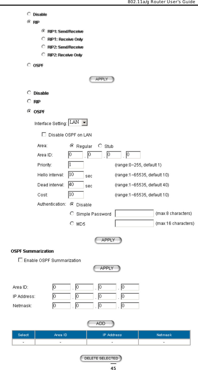
![802.11a/g Router User’s Guide RouteNetmask: the netmask of the destination network for the route. RouteInterface: the interface name that the route will go through. RouteGateway: the next gateway that the route will go through. RouteMetric: the metric for this route. Note: Either ‘RouteInterface’ or ‘RouteGateway’ can exist in an entry, not both nor none. [DynamicRouting] RoutingType=RIP RIPType=RIP2Active RoutingType=OSPF OSPFLan/OSPFWan=enable OSPFLanAreaID/OSPFWanAreaID=0.0.0.1 OSPFLanAreaType/OSPFWanAreaType=regular OSPFLanPriority/OSPFWanPriority=1 OSPFLanHelloInterval/OSPFWanHelloInterval=10 OSPFLanDeadInterval/OSPFWanDeadInterval=40 OSPFLanCost/OSPFWanCost=10 OSPFLanAuthType/OSPFWanAuthType=SP OSPFLanSPKey/OSPFWanmd5key=password OSPFWanMD5key=password OSPFRangeRule=enable OSPFRangeEntryAreaID=0.0.0.2 OSPFRangeEntryIPaddr=10.1.1.1 OSPFRangeEntryNetmask=255.255.255.0 Dynamic Routing Configuration RoutingType: dynamic routing type (‘disable’, ‘RIP’, ‘OSPF’). When ‘RoutingType’ is ‘RIP’: RIPType: the RIP mode (‘RIP1Active’, ‘RIP1Passive’, ‘RIP2Active’, ‘RIP2Passive’). When ‘RoutingType’ is ‘OSPF’: OSPFLan/OSPFWan: whether enable OSPF on the LAN/WAN interface (‘enable’, ‘disable’). If ‘OSPFLan’/’OSPFWan’ is ‘enable’, the following items are required. OSPFLanAreaID/OSPFWanAreaID: the Area ID that the LNA/WAN interface belongs to. OSPFLanAreaType/OSPFWanAreaType: the type of the area that the LAN/WAN interface belongs to (‘regular’, ‘stub’). OSPFLanPriority/OSPFWanPriority: the priority of the router on the LAN/WAN segment. OSPFLanHelloInterval/OSPFWanHelloInterval: the Hello interval on the LAN/WAN segment (unit: sec).OSPFLanDeadInterval/OSPFWanDeadInterval: the dead interval on the LAN/WAN segment (unit: sec).OSPFLanCost/OSPFWanCost: the cost to send a packet over the LAN/WAN interface. OSPFLanAuthType/OSPFWanAuthType: the authentication type of OSPF on the LAN/WAN segment (‘SP’: simple password, ‘MD5’). OSPFLanSPKey/OSPFWanSPkey: the password used for authentication if ‘OSPFLanAuthType’/’OSPFWanAuthType’ is ‘SP’. OSPFLanMD5Key/OSPFWanMD5key: the 83](https://usermanual.wiki/Wistron-NeWeb/CRP-1/User-Guide-420000-Page-84.png)
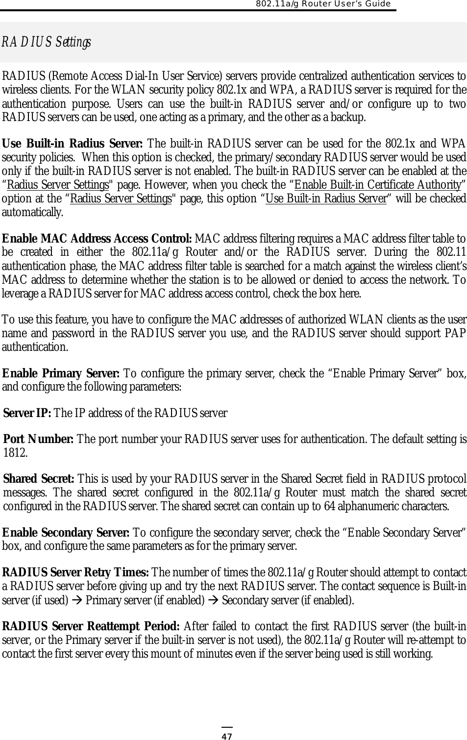
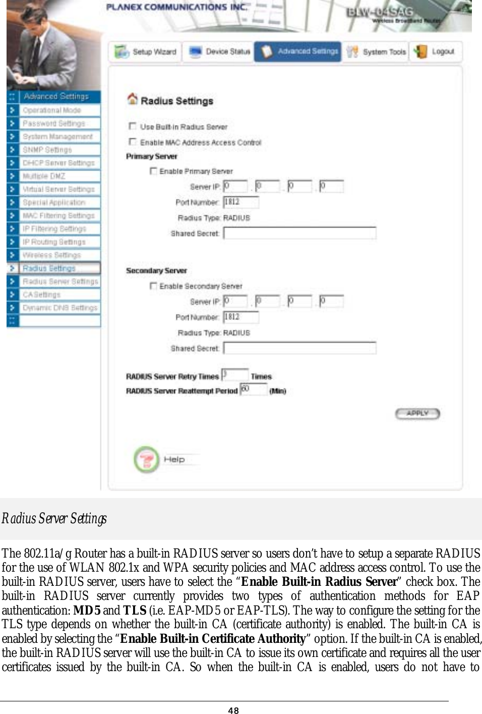
![password used for authentication if ‘OSPFLanAuthType’/’OSPFWanAuthType’ is ‘MD5’. OSPFRangeRule: whether enable route summarization (‘enable’, ‘disable’). OSPFRangeEntryAreaID/OSPFRangeEntryIPaddr/OSPFRangeEntryNetmas: a route destined to the specified area and matching the specified network address will be summarized. [RADIUS] RadiusRetryTimes=3 RadiusReattempPeriod=60 RadiusMACACLState=enable RadiusUseBuiltinServer=disable RADIUS Configuration RadiusRetryTimes: number of retries before giving up. RadiusReattempPeriod: re-attempt period (unit: minute). RadiusMACACLState: whether enable MAC address access control (‘enable’, ‘disable’) RadiusUseBuiltinServer: whether use the built-in RADIUS server first, if it exists (‘enable’, ‘disable’). [PrimaryRADIUS] [SecondaryRADIUS] RadiusPrimaryState=enable RadiusPrimaryIP=1.1.1.1 RadiusPrimaryPort=1812 RadiusPrimarySharedSecret=1111 RadiusSecondaryState=enable RadiusSecondaryIP=2.2.2.2 RadiusSecondaryPort=1812 RadiusSecondarySharedSecret=2222 External Primary/Secondary RADIUS Server Configuration RadiusPrimaryState/RadiusSecondaryState: whether use the external primary/secondary RADIUS server (‘enable’, ‘disable’). If the ‘RadiusPrimaryState’/’RadiusSecondaryState’ is ‘enable’, the following items have to be configured: RadiusPrimaryIP/RadiusSecondaryIP: the IP address of the external primary/secondary RADIUS server. RadiusPrimaryPort/RadiusSecondaryPort: the port number on the external primary/secondary RADIUS server. RadiusPrimarySharedSecret/ RadiusSecondarySharedSecret: the shared secret used for authentication with the external primary/secondary RADIUS server. [RadiusServer] RadiusSvrState=enable RadiusSvrCAState=disable RadiusSvrEAPAuthType=md5 RadiusSvrCertPasswd=passphrase RadiusSvrCert=Bag Attributes localKeyID:… RadiusSvrCACert= Bag AttributesBuilt-in RADIUS Server Configuration RadiusSvrState: whether enable the built-in RADIUS server (‘enable’, ‘disable’). RadiusSvrCAState: whether enable the built-in Certificate Authority (‘enable’, ‘disable’). RadiusSvrEAPAuthType: the authentication method used by the EAP function (‘md5’, ‘tls’). 84](https://usermanual.wiki/Wistron-NeWeb/CRP-1/User-Guide-420000-Page-85.png)
![802.11a/g Router User’s Guide localKeyID:… When ‘RadiusSvrCAState’ is ‘disable’ and ‘RadiusSvrEAPAuthType’ is ‘tls’, the following items should be configured: RadiusSvrCert: the certificate of the built-in RADIUS server. RadiusSvrCertPasswd: the password to use the built-in RADIUS server’s certificate. RadiusSvrCACert: the certificate of the CA issuing the built-in RADIUS server’s certificate. [RadiusClient] RadiusCltName=client1 RadiusCltIP=192.168.1.10 RadiusSecret=password RADIUS Client Database Configuration There could be multiple entries (max 20 entries), each entry contains the following items: RadiusCltName: a mnemonic name for the RADIUS client. RadiusCltIP: the IP address of the RADIUS client. RadiusSecret: the shared secret to authenticate the RADIUS client. [RadiusMD5UserEntry] RadiusMD5UserName=md5user RadiusMD5Passwd=password RADIUS MD5 User Database Configuration There could be multiple entries (max 20 entries), each entry contains the following items: RadiusMD5UserName/RadiusMD5Passwd: the user name and password for the MD5 user. [RadiusPAPUserEntry] RadiusPAPUserName=papuser RadiusPAPPasswd=password RADIUS PAP User Database Configuration There could be multiple entries (max 20 entries), each entry contains the following items: RadiusPAPUserName/RadiusPAPPasswd: the user name and password for the PAP user. [CA] CACertificate=-----BEGIN RSA PRIVATE KEY-----… Certificate Authority This section is used by the system to store the certificate of the built-in CA, no matter the built-in CA is enabled or not. Users should not modify the content this section. [DDNS] DDNSState=enable DDNSHostname=myname.mydomain.com Dynamic DNS Configuration DDNSState: whether the Dynamic DNS function is enabled (‘enable’, ‘disable’). 85](https://usermanual.wiki/Wistron-NeWeb/CRP-1/User-Guide-420000-Page-86.png)
![DDNSUserName=name DDNSPassword=password If ‘DDNSState’ is ‘enable’, following items have to be configured: DDNSHostname: the domain to use, which should be registered at DynDNS.org. DDNSUserName/DDNSPassword: the user name and password at DynDNS.org. [End] This is a dummy section that must be put at the end of a text configuration file. There is no key and value in this section, and any line below this section will be ignored. 86](https://usermanual.wiki/Wistron-NeWeb/CRP-1/User-Guide-420000-Page-87.png)